1
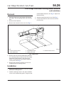
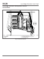
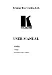
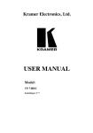
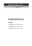
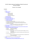
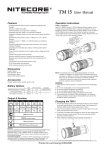
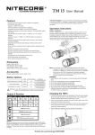
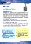
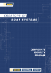
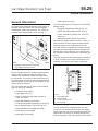
54.26
Low Voltage Disconnect, Sure Power
General Information
• Utility lights (circuit 73)
General Information
The optional low voltage disconnect (LVD) module is
mounted inside the driver’s side exterior baggage
compartment, against the back wall. The module is
protected by a molded plastic cover. See Fig. 1.
The LVD module will turn off power to the following
sleeper circuits:
• Baggage compartment lights (circuit 113)
• Dome and reading lights (circuit 41/41J)
• Power receptacles (circuits 57A, 57B, 57S,
and 416)
2
• Refrigerator/cooler power (circuit 57B)
Once battery voltage reaches 13 volts, or if the vehicle is started, the LVD module will automatically
reconnect power to the predetermined circuits.
The LVD module incorporates a 60-second time delay to prevent false triggering and is equipped with
internal short circuit protection, over current protection, transient voltage suppression, and thermal protection.
The LVD module has two terminal post connections,
a 10-pin connector port, and an LED indicator, all
mounted on the side of the module. See Fig. 2.
1
06/08/99
f542886
1. Baggage Compartment Door Opening
2. Low Voltage Disconnect Cover
Fig. 1, Low Voltage Disconnect Mounting
1
The low voltage disconnect module monitors battery
voltage levels. If battery voltage falls below 12.3
volts, the LVD module will sound a warning buzzer
for one minute. If no action is taken within that time,
the LVD module will remove power to predetermined
cab and sleeper circuits and an LED indicator on the
module will be illuminated.
2
3
K
J
H
G
F
A
B
C
D
E
4
The LVD module will turn off power to the following
main cab circuits (if installed):
• CB power (circuit 295C)
• Cigar lighter (circuit 5)
• Dome, reading and map lights (circuits 41,
108A, and 109A)
• Extra dash switches (circuit Opt.)
• Locating and positioning system (circuit 427A)
• Mirror heat and power (circuit 80 and 157)
• Power windows (circuit 363R and 363L)
• Radio power (circuit 295B)
• Road lights (circuit 28D)
Heavy-Duty Trucks Service Manual, Supplement 23, December 1999
06/24/99
1.
2.
3.
4.
f542882
Low Voltage LED
V-Out Terminal
10-Pin Connector Port
V-In Terminal
Fig. 2, Low Voltage Disconnect Module (side view)
The two terminal post connections are V-in and
V-out. The V-in terminal (circuit 447) is the voltage
supply input from the circuit breaker/relay panel, and
protects the LVD module by passing through a 50amp circuit breaker. The V-out terminal (circuit 447H)
050/1
54.26
Low Voltage Disconnect, Sure Power
General Information
is the controlled voltage output from the LVD module
to the ISO bus power input terminal of the circuit
breaker/relay panel (predetermined cab and sleeper
circuits). It also supplies power to the warning buzzer
(circuit 447J).
The 10-pin connector contains circuit 447B, which is
connected to the battery, and is used by the LVD
module to monitor the level of battery voltage. It contains the module’s ground circuit (GND), also connected to the battery; and it contains the warning
buzzer circuit (447G), which sounds the warning
buzzer when the LVD module detects low voltage.
050/2
Heavy-Duty Trucks Service Manual, Supplement 23, December 1999
54.26
Low Voltage Disconnect, Sure Power
Low Voltage Disconnect Module Removal and
Installation
Removal
2. Attach the protective plastic cover to the backwall with four Torx-head fasteners.
1. Park the vehicle on a level surface. Shut down
the engine. Set the parking brake and chock the
tires.
3. Close the baggage compartment door.
2. Disconnect the batteries.
4. Connect the batteries.
5. Remove the chocks from the tires.
3. Open the exterior baggage compartment door on
the left hand side, aft of the door. The low voltage disconnect module is located behind the protective plastic cover mounted on the back wall.
See Fig. 1.
2
4. Unfasten the four Torx® head fasteners and remove the protective plastic cover.
CAUTION
To prevent damage to the low voltage disconnect
module, remove the ground wire from the ground
terminal last.
1
5. Remove the low voltage disconnect module.
5.1
5.2
Note the position of the wiring on the terminals and remove the wiring from the
screw terminals on the side of the low
voltage disconnect module. See Fig. 2.
1. Baggage Compartment Door Opening
2. Low Voltage Disconnect Cover
Fig. 1, Low Voltage Disconnect Mounting
Remove the six mounting fasteners, three
above and three below the module, from
the baggage compartment backwall, and
remove the low voltage disconnect module.
1
Installation
2
1. Install the low voltage disconnect module inside
the left-hand exterior baggage compartment,
against the backwall.
1.1
f542886
06/08/99
3
Place the module against the backwall
and install the six Torx-head fasteners.
Tighten them firmly.
K
J
H
G
F
A
B
C
D
E
4
CAUTION
To prevent damage to the low voltage disconnect
module, connect the ground wire to the ground
terminal first.
1.2
Install the wiring to the terminals on the
top of the low voltage disconnect module.
See Fig. 2.
Heavy-Duty Trucks Service Manual, Supplement 23, December 1999
06/24/99
1.
2.
3.
4.
f542882
Low Voltage LED
V-Out Terminal
10-Pin Connector Port
V-In Terminal
Fig. 2, Low Voltage Disconnect Module (side view)
100/1
54.26
Low Voltage Disconnect, Sure Power
Low Voltage Disconnect Warning Buzzer Removal
and Installation
Removal
dard hardware fasteners. See Fig. 2. Tighten the
fasteners firmly.
1. Park the vehicle on a level surface. Shut down
the engine. Set the parking brake and chock the
tires.
3. Attach the electrical center cover. See Fig. 1.
4. Connect the batteries and remove the chocks
from the tires.
2. Disconnect the batteries.
3. Remove the electrical center cover. See Fig. 1.
2
3
1
4
5
04/11/96
1. Driver’s Instrument Panel
2. Center Dash Panel
f600593a
3. Glove Compartment
4. Heater–A/C Cover
5. Electrical Center Cover
Fig. 1, Dash Panel
4. Remove from the circuit breaker/relay panel the
two mounting fasteners that hold the low voltage
disconnect warning buzzer, and remove the
buzzer. The buzzer can be mounted anywhere
on the panel. See Fig. 2.
5. Remove the electrical connector from the low
voltage disconnect warning buzzer.
Installation
1. Attach the electrical connector to the low voltage
disconnect warning buzzer.
2. Install the warning buzzer in the space available
on the circuit breaker/relay panel, using two stan-
Heavy-Duty Trucks Service Manual, Supplement 23, December 1999
110/1
54.26
Low Voltage Disconnect, Sure Power
Low Voltage Disconnect Warning Buzzer Removal
and Installation
3
4
5
2
2
1
6
f542885
06/15/99
1. Junction Block
2. Bosch Relays
3. Bus Bar
4. 50-Amp Circuit Breaker
5. Low Voltage Disconnect Warning Buzzer
6. Circuit Breaker Panel
Fig. 2, Circuit Breaker Relay Panel
110/2
Heavy-Duty Trucks Service Manual, Supplement 23, December 1999