1
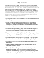
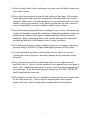
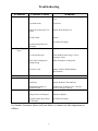
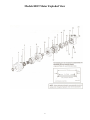
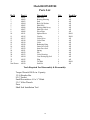
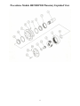
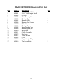
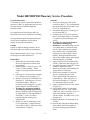
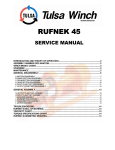
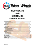
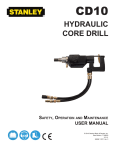
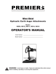
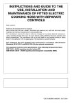
Premier
Augers
1631 East Pontiac Street
Fort Wayne, IN 46803
866-458-0008
Hydraulic Earth Auger
Operator’s Manual
Serial Number_____________
Model Number_____________
Models H005PD, H010PD, H015PD, H019PD, H024PD
Warning
Avoid Injury Or Death
Read And Understand This Entire Manual Before
Installing, Operating Or Servicing This Equipment
Table Of Contents
Safety Information
THE USE OF THIS EQUIPMENT IS SUBJECT TO CERTAIN HAZZARDS,
WHICH CANNOT BE PROTECTED AGAINST MECHANICAL MEANS OR
PRODUCT DESIGN. ALL OPERATORS OF THIS EQUIPMENT MUST READ
AND UNDERSTAND THIS ENTIRE MANUAL, PAYING PATICULAR
ATTENTION TO SAFETY AND OPERATING INSTRUCTIONS, PRIOR TO
USING THE PREMIER AUGERS HYDRAULIC EARTH AUGER. IF THERE
IS SOMETHING IN THIS MANUAL YOU DO NOT UNDERSTAND, ASK
YOUR SUPERVISOR TO EXPLAIN IT TO YOU. FAILURE TO OBSERVE
THESE SAFETY PRECAUTIONS CAN RESULT IN DEATH OR SERIOUS
INJURY OR SERIOUS EQUIPMENT DAMAGE.
1. All bystanders should be kept a minimum of 10 feet away from working area of
the earth auger.
2. Always wear an OSHA approved hard hat and safety eye protection when
operating or servicing this equipment. Do not wear loose fitting clothing,
flopping cuffs, dangling neckties and scarves, or rings and wrist watches that
can catch moving parts.
3. An operator must not use drugs or alcohol, which can change his alertness or
coordination. An operator taking prescription or over the counter drugs should
seek medical advice on whether or not he can safely operate equipment.
4. Always locate underground electrical wires, telephone cables, and gas, water,
and sewer lines before digging. Maintain safe clearance and avoid contact with
any underground or overhead utility lines or electrically charged conductors.
5. Never alter or remove any safety decals or safety shields. Check this manual
for location of these items and replace immediately if damaged or illegible.
6. Never adjust a relief valve for pressure higher than recommended by vehicle
manufacturer.
7. Whenever changing or installing this or other attachments, make sure all
connections are securely fastened.
8. Travel only with the earth auger in a safe transport position to prevent
uncontrolled movement. Drive slowly over rough ground and on slopes.
Tether earth auger with a chain, if necessary, to prevent uncontrolled swinging
of earth auger when moving from hole to hole. Remove earth auger from
vehicle when transporting to and from job site.
2
9. Before exiting vehicle, lower earth auger to ground, turn off vehicle engine and
lock vehicle breaks.
10.Never check a pressurized system for leaks with your bare hand. Oil escaping
from pinhole leaks under pressure can penetrate skin and could cause serious
infection. Hold a piece of cardboard up next to suspected leaks and wear a face
shield or safety eye protection. If any fluid is injected into the skin, it must be
removed immediately by a doctor familiar with this type of injury.
11.Before disconnecting hydraulic lines or fittings be sure to relieve all pressure by
cycling all hydraulic controls after shutdown. Remember hydraulic systems are
under pressure whenever the engine is running and may hold pressure after
shutdown. Before applying pressure to the system make sure all connections
are tight and that there is no damage to lines, fittings, and hoses.
12.Flow and pressure gauges, fitting, and hoses must have a continuous operating
pressure rating of at least 25% higher than highest pressures of the system.
13.Avoid steep hillside operation, which could cause the vehicle to overturn.
Consult your vehicle operator’s and safety manuals for the maximum incline
allowable.
14.Never perform any work on an earth auger unless you are authorized and
qualified to do so. Always read the operator service manual before any repair is
made. After completing maintenance or repair, check for correct functioning of
the earth auger. If not functioning properly always tag “DO NOT OPERATE”
until all problems are corrected.
15.This manual covers the safe use, installation, operation, and service instructions
for the earth auger only. Always read the operating and safety manuals
prepared for your vehicle and any other attachments before using them.
3
H019SDP200
Installation Instructions
1. 40030
2. 40031
3. 91006
4. 91007
5. 60003
6. 61004
7. 61002
8. 61003
9. 65002
10.40009
Long Pin
Short Pin
Swivel
Housing
Hydraulic Motor
Motor Fittings
Check Valve
Breather Vent
Planetary
Snap Pin (Not Shown)
1. READ AND UNDERSTAND ALL SAFETY INFORMATION PRIOR TO
ATTEMPTING INSTALLATION.
2. Refer to the “Hydraulic System Hook-up” section in this manual for hydraulic
connection instructions and recommendations.
4
Hydraulic System Hook-Up Instructions
1. Once the installation instructions are complete you are now ready to make the
hydraulic connections necessary to operate your earth drill. Read and
understand safety information prior to making hydraulic connections.
2. Model H019SDP200 requires two ½” I.D. hoses with #10 JIC female fittings on
one end of each to connect hoses to drive unit fittings.
3. Once all hydraulic connections have been made and checked for leaks and
proper hose lengths, you are now ready to operate your earth drill. Read and
understand operating instructions and safety information prior to
operating your earth drill.
WARNING! HOSES AND FITTINGS MUST HAVE A CONTINUOUS
OPERATING PRESSURE RATING OF AT LEAST 25% HIGHER THAN
HIGHEST PRESSURES OF THE SYSTEM YOU ARE “TAPPING” INTO.
5
Operating Instructions
1. After all installation instructions have been completed, safety information read and
understood and the rest of this operator’s manual has been reviewed, your Hydraulic Earth
Drill is now ready to use.
2. With the auger raised off the ground and the vehicle engine set at a low RPM, activate the
earth drill control valve to determine position control valve lever must be in to turn auger in a
forward (clockwise) rotation. This is the “digging” position.
3. Before beginning to dig, experiment with auger speed to determine a suitable auger RPM.
Generally in light and sandy soil a high RPM is desirable. In hard, rocky, or frozen soils a
slower RPM is desirable. To increase auger RPM, increase vehicle engine RPM. To
decrease auger RPM, decrease vehicle engine RPM.
4. Return earth drill control valve to neutral position to stop the auger. Lower the auger to the
ground so that only the center point penetrates the ground about 2”.
5. Activate the earth control valve so auger is turning in a forward (clockwise) rotation. Use
only enough down pressure to assure positive penetration of auger into the ground. Ease up
on down pressure if auger rotation slows down drastically or stalls. Excessive down pressure
will cause the auger to stall frequently.
6. When the auger has penetrated the ground about 24”, raise the auger from the hole to clean
the dirt out. Repeat this procedure until the desired hole depth is obtained.
7. Once the required hole depth is reached, allow the auger to turn a few seconds at this depth to
clean the hole.
8. Return the earth drill control valve to the neutral position to stop the rotation of the auger.
Raise the auger out of the hole, move away from the hole, then activate the earth drill control
valve to spin the loose soil off of the augers.
9. If necessary, repeat steps 7 & 8 to obtain a cleaner hole.
10. In some soil conditions or when excessive down pressure is applied, auger may “screw” itself
into the ground and become stuck causing earth drill to stall. If this happens, reverse the
auger rotation (counter Clockwise) by moving the control valve lever to the reverse position
and slowly raise the auger. Once unstuck, return the control valve lever to the forward
position and continue digging.
11. If the auger becomes lodged under rocks, roots, or other large obstructions, do not attempt to
raise auger out of the ground. See step 10 for proper procedure to relieve the auger.
12. Avoid excessive side loading to the earth drill which can cause drive unit or auger damage.
13.Keep auger teeth and points in good condition. Check frequently and always keep spares on
hand so they can be replaced as wear is detected to avoid damage to tooth holders and auger
flighting.
6
Maintenance Instructions
1. CLEAN HYDRAULIC OIL IS ESSENTIAL! 80% of all hydraulic component failures are
caused by contamination of the hydraulic oil. Always keep all dirt and other contaminates
from entering hydraulic system during disconnect and connect operations. Always use dust
caps and plugs on all quick disconnects when not in use. Tightly cap all hydraulic openings
to hold oil in and keep dirt and other contaminates from entering hydraulic systems.
2. CHECK ALL HYDRAULIC OIL DAILY FOR CONTAMINATION. If contamination is
present, determine the source of the problem.
3. INSPECT ALL HYDRAULIC HOSE ASSEMBLIES DAILY for cracked and brittle covers
caused by excessive heat. Reduced viscocity of hydraulic oil occurs at higher operating
temperatures and causes a breakdown of fluid additives such as wear inhibitors. Excessive
heat will cause higher internal leakage in drive unit motor to become brittle and crack.
Replacement of hoses before failure will prevent loss of hydraulic oil, time consuming
“bleeding” of system, hydraulic oil contamination, and component damage caused by
cavitations. It will also reduce the chance of personal injury caused by hydraulic fluid.
4. CHECK AUGER DAILY for loose, worn or broken cutting teeth and point. Worn teeth or
point can drastically affect auger penetration and greatly reduce auger life expectancy.
Always keep spare teeth and points on hand. Some digging conditions may require checking
teeth and point at more frequent intervals.
5. CHECK DRIVE UNIT AND ALL ACCESSORIES DAILY for loose, bent, cracked, or
worn, bolts and fasteners. Always use grade 5 or better replacement bolts. Always use lock
washers with standard hex nuts or self locking nuts.
6. CHECK ALL CONNECTING PINS DAILY for bends, cracks, breaks, or wear. Replace if
any of these conditions exist.
7. CHECK DRIVE UNIT OUTPUT SHAFT DAILY for bends, cracks, breaks, or wear.
Replace if any of these conditions exist.
8. CHANGE PLANETARY GEAR REDUCTION OIL AFTER FIRST 50 HOURS OF
OPERATION, THEN EVERY 1000 HOURS OR IN ONE YEAR, WHICHEVER COMES
FIRST. Use mild extreme pressure lubricant API-GL-5 number 80 or 90 for filling planetary
gear reduction under normal temperature ranges between 0 degrees and 120 degrees.
Approximate oil capacity for model H019SDP200 is two pints. Check oil level daily to
assure proper lubrication is maintained.
9. WHEN STORING DRIVE UNIT for any length of time be sure drive unit motor and hoses
are full of clean oil. Also, be sure that planetary gear reduction is full to the recommended
capacity for each model as outlined in number 8 above.
10. Drive unit output shaft, inside of auger collar, variable auger extension shaft, inside of
variable auger extension collar and all connecting pins should be coated liberally with grease
as required to prevent rust and reduce wear.
11. Once paint has been worn off auger, coat liberally with grease as required, to prevent rusting.
12. Check planetary gear oil as follows. Lie drive unit horizontal with ground place bottom drain
plug straight up. Remove plug, tilt drive unit at 2:00 or 10:00. Fill until oil leaks out from
hole at one of these positions.
7
Troubleshooting
Problem
Slow Speed
Possible Cause
Solution
Low Flow
Check With Flow Meter. If Low Investigate
cause.
Line Restrictions
Clear Lines
Fittings Or Connections Too
Small
Replace With Proper Sizes.
Oil Filter Dirty
Replace
See Dealer For Repair
Insufficient Digging
Power
Hydraulic Pump Worn Or
Damaged
Worn Teeth Or Point
Replace
Low System Pressure
Check With Pressure Gauge. If Low
Investigate Cause.
Relief Valve Damaged Or
Setting Wrong
Adjust Or Replace As Required
Excessive Load
Reduce Load To Within Machine
Specifications
Reverse Direction
Hoses Reversed
Excessive Oil Heating Line Restrictions
Oil Leaks
Re-Install Hoses Correctly
Clear Lines
Fluid Dirty
Replace Hydraulic Fluid & Filter
Insufficient Quantity Of
Hydraulic Fluid
Hoses Loose Or Damaged
Fill Reservoir To Proper Level. Increase
Reservoir Storage Capacity.
Tighten Or Replace
Fittings Loose Or Damaged
Tighten Or Replace
Hydraulic Motor Seals Worn
Or Damaged
See Dealer For Repair
For Further Assistance, please call your dealer, or contact our sales department as
follows:
8
Models H019 Motor Exploded View
9
Model H019SDP200
Parts List
Ref.#
Part #
Description
Qty
Used On
1
2
3
4
5
7
8
9
10
11
12
13
14
15
16
17
18
19
20
21
22
23
Not Shown
62001
62002
62003
62004
62005
62006
62007
62008
62011
62015
62017
62018
62019
62020
62021
62022
62021
62022
62023
62024
62025
62028
62030
Dust Seal
Bearing Housing
Seal
Back Up Washer
Shaft Seal
Bearing Shaft Assy
Shaft Face Seal
Wear Plate
Splined Drive
Geroler
Valve Drive
Valve Plate
Valve
Balancing Ring
Outer Face Seal
Inner Face Seal
Spring
Pin
Valve Housing
Case Drain plug Seal
Plug
Tie Bolt
Seal Kit
1
1
4
1
1
1
1
1
1
1
1
1
1
1
1
1
2
2
1
1
1
4
1
All
All
All
All
All
All
All
All
H019
H019
All
All
All
All
All
All
All
All
All
All
All
H019
All
Tools Required For Disassembly & Reassembly:
Torque Wrench 500 lb. in. Capacity
12-16 Breaker Bar
9/16” Socket
Small Screwdriver 6-8 x ¼” Blade
3/16” Allen Wrench
Press
Shaft Seal Installation Tool
10
Procedures Models H019SDP200 Planetary Exploded View
11
Model H019SDP200 Planetary Parts List
Ref#
1
1
2
3
4
5
6
7
8
9
10
11
12
13
14
15
16
17
Part #
69000
69001
69002
69003
69004
69005
69006
69007
69004
69008
69009
69010
69011
69012
69013
69014
69015
69016
Description
2” Hex Output Shaft
2-9/16” Rnd Output Shaft
Oil Seal
Outer Bearing Cones
Bearing Cup
Housing Bolt
Housing Flat Washer
Hub
Bearing Cup
Inner Bearing Cone
Retaining Ring Set
Ring Gear
Carrier Assembly
Sun Gear
Thrust Washer
Cover
Magnetic pipe Plug
Top Cover Bolts
12
Qty
1
1
1
1
2
6
6
1
1
1
1
1
1
1
1
1
1
8
Model H019SDP200 Planetary Service Procedure
General Instructions:
To facilitate the repair of these units and before
any work is done, we suggest that you first read
all of the steps used in disassembly and
assembly of unit.
Assembly:
1. Press new bearing cups (4 & 8) into
each side of hub (7). It is recommended
that the bearing cups (4 & 8) and Cones
(3 & 9) be replaced in sets.
2. Assemble bearing cone (3) into cup (4)
at seal end of Hub (7).
3. Lubricate lips of oil seal (2) and lower
hub (7) onto output shaft (1). Keep hub
(7) centered to prevent damage to oil
seal (2).
4. Warning! Eye protection should be
worn during retaining ring
installation. Assemble bearing cone (8)
over output shaft (1) and into bearing
cup (8). Select the thickest retaining
ring (10) that can be assembled into
ring groove on output shaft (1) above
bearing. Bearings should have from
.000 to .006 inches endplay when proper
retaining ring (10) is installed.
5. Apply a bead of silicone sealant to face
of hub (7) that mates with ring gear (11).
6. Assemble ring gear (11) to hub (7) being
careful to align all bolt holes.
7. Install six hex bolts (5) and washers (6).
Torque bolts to 52-60 ft/lbs.
8. Place carrier assembly (12) into ring
gear (11) aligning the gear teeth.
Carrier splines mesh with splines on
output shaft (1). Place sun gear (13)
into carrier assembly (12). Sun gear
(13) should turn freely by hand.
9. Apply a bead of silicone to cover face of
ring gear (11).
10. Secure thrust washer (14) with tangs
engaged in cover (15). Note: Thrust
washer (14) can be secured to cover (15)
with a small amount of grease or
silicone sealant. Assemble cover (15) to
ring gear (11).
11. Install eight bolts (17) and torque to 2025 ft/lbs.
12. Position unit with output shaft pointing
down and fill until oil just begins to
flow from fill plug (approximately 2
pints).
It is important to air blast all parts and wipe
them with clean, lint less cloth before assembly.
It is a good idea to check all replacement parts
closely before installing to ensure that no
damage occurred during shipment.
Caution
If parts are stubborn during assembly, do not
force them and never employ an iron hammer.
Never hammer bearing cones or cups. Use only
an arbor press or other suitable tool.
Disassembly:
1. Index mark all sections with a punch.
Be sure to align all these marks when
reassembling.
2. Remove bolts(17) from cover(15). Lift
cover (15) from assembly. Thrust
washer (14) usually remains with cover
(15).
3. Lift sun gear (13) from carrier assembly
(12). Remove carrier assembly (12).
4. Remove 6 hex bolts (5) and washers (6)
from hub (7). Pull ring gear (11) from
remaining assembly. It may be
necessary to strike ring gear (11) with a
rubber mallet to loosen from hub (7)
5. Warning! Eye protection should be
worn during retaining ring removal.
Remove retaining ring (10) from groove
in output shaft (1). Pull output shaft (1)
from Hub (7). Note: To remove
retaining ring use retaining ring
expander tool.
6. Remove oil seal (2) and bearing cones
(3 & 9) from hub (7). Inspect bearing
cups (4 & 8) in hub (7) and remove only
if replacement is required.
13