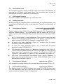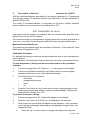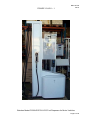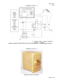
1
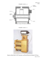
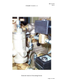
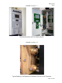
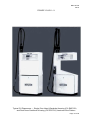
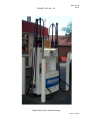
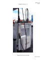
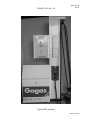
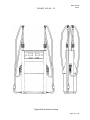
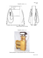
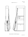
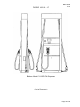
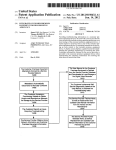
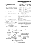
NMI 10/1/20
Rev 8
Bradfield Road, West Lindfield NSW 2070
Certificate of Approval
NMI 10/1/20
Issued by the Chief Metrologist under Regulation 60
of the
National Measurement Regulations 1999
This is to certify that an approval for use for trade has been granted in respect of
the instruments herein described.
Batchen Model C2000-DCE-PA LPG Fuel Dispenser for Motor Vehicles
submitted by
D J Batchen Pty Ltd
2-6 Raglan Road
Auburn
NSW
2144
NOTE: This Certificate relates to the suitability of the pattern of the instrument for
use for trade only in respect of its metrological characteristics. This Certificate
does not constitute or imply any guarantee of compliance by the manufacturer or
any other person with any requirements regarding safety.
This approval has been granted with reference to document NMI R 117 Measuring
Systems for Liquids Other than Water, dated June 2011.
This approval becomes subject to review on 1/09/18, and then every
5 years thereafter.
DOCUMENT HISTORY
Rev
0
1
2
3
4
5
6
7
8
Reason/Details
Pattern & variant 1 provisionally approved – interim certificate
issued
Pattern & variant 1 provisionally approved – interim certificate
issued
Variant 2 approved – certificate issued
Pattern amended (self-serve) – notification of change issued
Variant 3 approved – interim certificate issued
Variant 3 approved – certificate issued
Pattern & variants 1 to 3 amended & reviewed – variant 4
approved – certificate issued
Pattern amended (density range) – notification of change
issued
Pattern & variants 1 to 4 reviewed & updated – certificate
issued
Date
14/08/01
29/10/01
10/12/01
11/01/02
27/06/02
16/09/02
22/08/06
10/03/10
14/04/14
Page 1 of 20
NMI 10/1/20
Rev 8
CONDITIONS OF APPROVAL
General
Instruments purporting to comply with this approval shall be marked with pattern
approval number ‘NMI (or NSC) 10/1/20’ and only by persons authorised by the
submittor.
Instruments purporting to comply with this approval and currently marked ‘NSC
P10/1/20’ may be re-marked ‘NMI (or NSC) 10/1/20’ but only by persons
authorised by the submittor.
It is the submittor’s responsibility to ensure that all instruments marked with this
approval number are constructed as described in the documentation lodged with
the National Measurement Institute (NMI) and with the relevant Certificate of
Approval and Technical Schedule. Failure to comply with this Condition may
attract penalties under Section 19B of the National Measurement Act and may
result in cancellation or withdrawal of the approval, in accordance with document
NMI P 106.
Auxiliary devices used with this instrument shall comply with the requirements of
General Supplementary Certificates No S1/0/A or No S1/0B.
Signed by a person authorised by the Chief Metrologist
to exercise their powers under Regulation 60 of the
National Measurement Regulations 1999.
Dr A Rawlinson
Page 2 of 20
NMI 10/1/20
Rev 8
TECHNICAL SCHEDULE No 10/1/20
1.
Description of Pattern
provisionally approved 14/08/01
approved 29/10/01
The Batchen model C2000-DCE-PA is a fuel dispenser for refuelling motor
vehicles using liquefied petroleum gas (LPG). The dispenser is approved for use
in attendant-operated mode, or in attended self-service mode using any
compatible (#) approved control console.
The model number may be without the 'PA' suffix, e.g. the pattern (model C2000DCE-PA) may also be known as the model C2000-DCE.
(#)
‘Compatible’ is defined to mean that no additions/changes to
hardware/software are required for satisfactory operation of the complete
system.
The model C2000-DCE-PA dual (twin) LPG dispenser (Figures 1 and 2) includes
the following components or features:
A Batchen model Mk-V constant bleed vapour elimination device.
Two Batchen model Mk III LPG liquefied petroleum gas (LPG) flowmeters
each fitted with an Email Electronics model VN pulse generator.
Two Batchen model Mk VI spring-loaded pressure differential valves.
A calculator/indicator configured for use with a density detection device
enabling the volume conversion to 15°C.
An optional pre-setting device.
1.1
Field of Operation
The field of operation of the measuring system is determined by the following
characteristics:
•
•
•
•
•
•
•
•
Minimum measured quantity, Vmin
2L
Maximum flow rate, Qmax
60 L/min
Minimum flow rate, Qmin
10 L/min
Maximum pressure of the liquid, Pmax
2450 kPa
LPG density detection range (at 15°C)
500 kg/m³ to 590 kg/m³
Ambient temperature range
-10 to 55°C
Volume conversion to 15°C over a liquid
temperature range of
-10°C to 45°C
Operating pressure is maintained at least 200 kPa above the
Equilibrium vapour pressure of LPG.
Accuracy class
1.0
1.2
System Description
(i)
The supply tank may be located above or below ground.
(ii)
The pump may be positioned above the supply tank, in which case the
pump shall be a multi-stage regenerative turbine LPG pump especially
designed for use in suction lift installations. Alternatively, the pump shall
be positioned below the supply tank so that it is always in a state of flooded
suction (suction head installations). There are no restrictive fittings within
ten pipe diameters of the pump inlet.
•
Page 3 of 20
NMI 10/1/20
Rev 8
The inlet pipe to the pump is larger than the outlet from the pump. The
external pump by-pass relief valve is installed in a line returning to the
vapour space of the supply tank.
A pump supplying LPG to several flowmeters shall be of sufficient capacity
rating to ensure that when all flowmeters are in use the flow rate through
each flowmeter is greater than Qmin.
(iii)
A Batchen constant bleed vapour eliminator with an integral strainer
(Figures 3 and 4) positioned upstream of each flowmeter, in conjunction
with a pressure differential valve downstream of each flowmeter, protect the
flowmeters from the measurement of vapour. The thermometer well for
checking the temperature measurement of LPG is situated in the top of the
vapour eliminator.
(iv)
Two Batchen model Mk III two-piston LPG flowmeters are used (Figure 5)
each fitted with an Email Electronics model VN pulse generator with an
output of 100 pulses per revolution.
(v)
A Batchen model Mk VI spring-loaded pressure differential valve is fitted to
the flowmeter outlet. A pressure-equalising pipe is connected from the top
of the differential valve to the vapour space of the supply tank. The
differential valve may be fitted with one or more bleed valves. In normal
operation, the bleed valves are sealed with caps to prevent leakage.
(vi)
A Batchen hydraulic accumulator may be fitted downstream of the pressure
differential valve.
(vii)
A 1/2” NPT flow solenoid valve is located downstream of the pressure
differential valve. The solenoid valve controls the delivery and prevents
delivery during the reset cycle. If a pre-setting device is fitted, the system
will also include a 1/4” NPT flow solenoid valve (Figure 6).
(viii)
The fuel dispenser is fitted with hoses of 15 or 20 mm nominal bore and
incorporating a Batchen model Sentry 20 hose beak-away coupling fitted
between the flow solenoid valve and the nozzle.
The nozzles used are either Gasguard model LG1DNS or any other
compatible NMI-approved LPG nozzle, suitable for the hang-up mechanism.
Note that the submittor must be consulted regarding the acceptability of any
alternative nozzles.
(ix)
The calculator/indicator (Figure 7) comprises an Email model Vision
computing board and two Email model Vision display boards. The indicators
display the following maximum values:
Volume 999.99 L in 0.01 L increments
Unit price 999.9 c/L in 0.1 cent increments
Total price $999.99 in 1 cent increments
Totaliser (volume) 99999 L in 1 L increments
Pre-set (optional) $999 in $1 increments
The calculator/indicator can display LPG density at 15°C used for
conversion of volume to 15°C, and can display the temperature of LPG
flowing through the meter (refer Test Procedure).
The main software version number for the calculator/indicator is B4.###
which may be viewed using the ‘test’ button (refer to the Test Procedure).
Page 4 of 20
NMI 10/1/20
Rev 8
1.3
Operation
Removal of the nozzle from its hang-up starts the operating cycle. The display will
be cleared of any previous sale and the remote pump will start. The system
electronics will automatically check for pulse generator rotation and correct
electronic parameters.
A segment check is initiated; when completed the unit price is displayed and the
price and volume displays show all zeroes. At the end of this cycle, the flow
solenoid valve opens allowing a delivery to commence. Replacing the nozzle to its
normal hang-up position closes the solenoid valve. The delivery details are
displayed until the next reset cycle.
1.4
Volume Conversion Device
The electronic volume conversion for temperature facility is used to convert the
measured volume to volume at 15°C using the volume conversion factors as a
function of density in accordance with Table 54 of the ASTM-IP-API Petroleum
Measurement Tables for Light Hydrocarbon Liquids.
The calculator/indicator is configured for use with an LPG Measurement model
DSS -98 (*) density detector probe to display the delivered volume at 15°C.
(*)
DSS -98 where
is either B or P, depending on type of connection.
1.5
Descriptive Markings and Notices
Instruments are marked with the following data, together in one location on a data
plate:
Pattern approval number
NMI (or NSC) No 10/1/20
Manufacturer’s identification mark or name
.....
Manufacturer’s designation (model number)
.....
Serial number .
....
Year of manufacture
.....
Maximum flow rate (Qmax)
..... L/min
Minimum flow rate (Qmin)
..... L/min
Minimum measured quantity (Vmin)
..... L
(#1)
Maximum operating pressure (Pmax)
2450 kPa
Minimum pressure (Pmin)
200 kPa above vapour pressure (#2)
Approved for LPG density range
500 kg/m³ to 590 kg/m³ (at 15°C)
Maximum liquid temperature (Tmax)
.....°C
Minimum liquid temperature (Tmin)
.....°C
Accuracy class class
1.0
Environmental class
class C
(#1)
The minimum measured quantity (Vmin) shall be clearly visible on any
indicating device visible to the user during measurement.
(#2)
Alternatively, the following wording may be used:
‘LPG pressure (at the meter) is maintained at least 200 kPa above vapour
pressure.’
Note: The words ‘at the meter’ may be deleted to save space.
Page 5 of 20
NMI 10/1/20
Rev 8
1.6
Recirculation Line
A recirculation line with a double check filler valve is provided at the dispenser for
returning the LPG back to the supply tank. The recirculation line is used for
maintenance checking or calibration of the dispenser.
1.7
Verification Provision
Provision is made for the application of a verification mark.
1.8
Sealing Provision
A plate covering the calibration switch situated inside the calculator/indicator, and
the mechanical calibration device on the flowmeter (Figure 8), have provision for
sealing.
2.
Description of Variant 1
provisionally approved 14/08/01
approved 29/10/01
Certain models of the C2000 (‘Concept 2000’) series or CII (‘Commander II’)
series as identified below: (The model number may be without the 'PA' or ‘SA’
suffix, e.g. the model C2000-DCE-SA) may also be known as the model C2000DCE.)
As CII (‘Commander II’) series dispensers (Figure 9) which have the same
features and metrological specifications as the pattern, in which case the
pattern (model C2000-DCE-PA) becomes a model CII-DCE-PA.
As single (one hose) dispensers (Figure 9), in which case the pattern
becomes a model C2000-SCE-PA.
As quad (four hose) dispensers (Figure 10), in which case the pattern
becomes a model C2000-QCE-PA.
With alternative housing styles, e.g. ‘Wardrobe’ (rectangular) style (Figure 9),
in which case the pattern becomes a model C2000-DWE-PA. Other housing
styles (and their codes) are ‘twin column’ (T) (Figure 11), ‘MPP’ (M)
(Figure 12), ‘end oriented’ (J) (Figure 13), and ‘handed twin’ (H) (Figure 14).
With lower (non-metrological) specification levels, namely ‘Standard’, in
which case the pattern becomes a model C2000-DCE-SA. Refer to the
optional items marked in Figure 2.
3.
Description of Variant 2
approved on 10/12/01
With a magnetic coupling between the meter and the pulse generator (Figure 15).
4.
Description of Variant 3
approved on 27/06/02
The Batchen model C11-SEE-PA (single) and model C11-DEE-PA dual (twin)
LPG fuel dispensers which are similar to the pattern but in alternative housing
styles as shown in Figures 16 and 17, respectively.
Page 6 of 20
NMI 10/1/20
Rev 8
5.
Description of Variant 4
approved on 21/08/07
With the calculator/indicator described for the pattern replaced by a Transponder
Technologies model T5 calculator/indicator (as described in the documentation of
approval NSC S414).
The model T5 calculator/indicator is configured for use with a density detection
device enabling volume correction for temperature to 15oC.
TEST PROCEDURE No 10/1/20
Instruments shall be tested in accordance with any relevant tests specified in the
National Instrument Test Procedures.
The instrument shall not be adjusted to anything other than as close as practical to
zero error, even when these values are within the maximum permissible errors.
Maximum Permissible Errors
The maximum permissible errors are specified in Schedule 1 of the National Trade
Measurement Regulations 2009.
Calibration Procedure
For detailed configuration and code setting procedures, refer to the manufacturer’s
service manual.
The calibration of the flowmeter shall be carried out using the unconverted volume.
To view temperature, density and unconverted volume on the calculator/
indicator:
1.
Turn the manager’s key 90°. Dashes (‘-----‘) will appear on the display.
2.
There are four buttons marked by dots, broken lines or pre-set keypad,
situated on the front or rear of the indicator/calculator.
3.
The buttons from left to right are:
•
test button
•
manager digit change
•
down
•
up
4.
Press the ‘test’ button to view unconverted volume. Keep pressing to view
temperature, density and software version number (B4.###). Note that the
displayed LPG density is at 15°C.
To perform a unit price change
1.
Turn the manager’s key 90°. Dashes will appear on the display.
2.
Press the ‘test’ button until ‘Set Price’ is displayed by the indicator.
3.
Lift a nozzle and a small digit will appear on the indication – this correlates
to the digit being changed, and pressing ‘manager/digit change’ button can
change this digit.
4.
Press the ‘up’ or ‘down’ button to change each digit of the unit price.
Page 7 of 20
NMI 10/1/20
Rev 8
FIGURE 10/1/20 – 1
Batchen Model C2000-DCE-PA LPG Fuel Dispenser for Motor Vehicles
Page 8 of 20
NMI 10/1/20
Rev 8
FIGURE 10/1/20 – 2
Batchen Model C2000-DCE-PA LPG Fuel Dispenser — Single System Shown
FIGURE 10/1/20 – 3
Batchen Vapour Eliminator
Page 9 of 20
NMI 10/1/20
Rev 8
FIGURE 10/1/20 – 4
Batchen Vapour Eliminator (Diagram)
FIGURE 10/1/20 – 5
Batchen Model Mk III LPG Flowmeter and Email Electronics Model VN Pulser
Page 10 of 20
NMI 10/1/20
Rev 8
FIGURE 10/1/20 – 6
Solenoid Valve for Pre-setting Device
Page 11 of 20
NMI 10/1/20
Rev 8
FIGURE 10/1/20 – 7
Calculator/Indicator With Pre-setting Device
FIGURE 10/1/20 – 8
Typical Sealing of the Mechanical Calibration Device on the Flowmeter
Page 12 of 20
NMI 10/1/20
Rev 8
FIGURE 10/1/20 – 9
Typical CII Dispensers — Single (One Hose) Wardrobe Housing (CII-SWE-PA)
and Dual Hose Cantilever Housing (CII-DCE-PA) Versions of the Pattern
Page 13 of 20
NMI 10/1/20
Rev 8
FIGURE 10/1/20 – 10
Typical Quad (Four Hose) Housing
Page 14 of 20
NMI 10/1/20
Rev 8
FIGURE 10/1/20 – 11
Typical Twin Column Housing
Page 15 of 20
NMI 10/1/20
Rev 8
FIGURE 10/1/20 – 12
Typical MPP Housing
Page 16 of 20
NMI 10/1/20
Rev 8
FIGURE 10/1/20 – 13
Typical End Oriented Housing
Page 17 of 20
NMI 10/1/20
Rev 8
FIGURE 10/1/20 – 14
Typical Handed Twin Housing
FIGURE 10/1/20 – 15
Showing Magnetic Coupling Between Meter and Pulse Generator
Page 18 of 20
NMI 10/1/20
Rev 8
FIGURE 10/1/20 – 16
Batchen Model C11-SEE-PA Dispenser
Page 19 of 20
NMI 10/1/20
Rev 8
FIGURE 10/1/20 – 17
Batchen Model C11-DEE-PA Dispenser
~ End of Document ~
Page 20 of 20