1
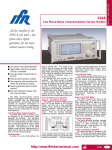
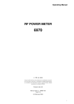
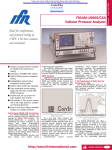
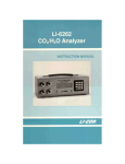
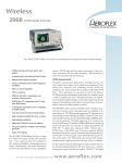
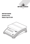
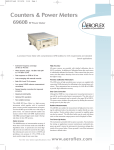
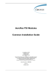
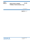
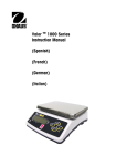
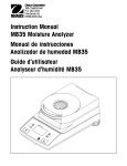
Counters & Power Meters CPM 20, 46 Counter Power Meter A ruggedized solution for microwave power and frequency measurements in the field Combined Frequency Counter and Power Meter in one unit Two models available: 10 MHz to 20 GHz 10 MHz to 46 GHz Large, easy to read screen allows simultaneous display of both power and frequency measurements Built-in DVM for AGC voltage measurements Designed for use in the field, weighing only 4.9 kg (10.8 Ib) and battery operated Supported by the full range of IFR power sensors IFRs Counter Power Meter (CPM) is a portable combination of three instruments: a Microwave Frequency Counter, true Power Meter and Digital Voltmeter. A compact instrument with internal rechargeable battery, ruggedized case and carrying strap, it can be used up a tower, on a roof top or at a field site. Digital microwave radios are commonly installed for network access to mobile radio cell sites and quick installation of business communications. The CPM is the ideal instrument for installation and maintenance engineers working on these systems. Designed for Field Use The CPM weighs 4.9 kg (10.8 Ib), including battery, which makes it ideal for taking up radio towers or carrying on to exposed roof top sites. A supplied accessory pouch contains and protects all the required accessories. The rechargeable battery gives three hours of continuous operation. Batteries can be charged from either the supplied AC adapter or a vehicle supply. Battery life is continuously monitored and the display shows the percentage life remaining. As accessories a spare battery and desktop charger are available. The display uses transflective LCD technology which has an integral backlight. This means that it can easily be read both outdoors in direct sunlight and indoors in low light. The user interface makes operation fast, simple and reliable. Measurements are swiftly configured, connections are clearly marked and results are easy to read. Accuracy Despite being lightweight and portable, there is no compromise in accuracy. The standard reference oscillator is a DTCXO, digitally controlled temperature compensated crystal oscillator. A DTCXO has no warm up time and is ready to make accurate measurements immediately after switch on, saving both time and battery life. Power measurement accuracy is guaranteed through the use of the standard IFR 6900 series of power sensors. These sensors have excellent return loss specifications which minimize mismatch errors in power measurements. Calibration and linearity factors, unique to each sensor, can also be entered into the CPM to ensure the best accuracy at all times. An integral 0 dBm, 50 MHz power reference is used for sensor calibration, ensuring measurement accuracy and traceability to national standards. Fully Featured Two versions of the CPM are available, CPM 20 measures frequencies from 10 MHz to 20 GHz and CPM 46 from 10 MHz to 46 GHz, through a single input. Power sensors cover the frequency range 30 kHz to 46 GHz, and when used with a CPM measure -60 dBm to +44 dBm (25 W). The frequency counter has relative frequency and frequency offset modes for frequency drift and frequency conversion measurements. A limits function enables frequency to be measured against a specification, with pass/fail annunciator in the display. Resolution is user settable from 1 Hz to 1 MHz. CPM is designed for radio link testing The power meter features pass/fail limits, dB rel, power offset and duty cycle modes. An analog peaking meter is displayed for tuning and adjusting power levels. A built-in DVM complements the frequency counter and power meter. Radio http://www.ifrinternational.com CPM 20, 46 1 CPM 20, 46 links are often aligned by monitoring the receiver AGC voltage. The DVM, with its clear 10 mV resolution readout and analog peaking meter, is ideally suited to this task. Units dBm, dBW, pW, nW, µW, mW, W, kW Features Limit checking, Duty cycle, dB Relative, Power offset, Analog Meter Correction Linearity Factor Calibration Factor Specification Auto-Calibration Ability to calibrate against a 0 dBm (1 mW), 50 MHz power reference Frequency Measurement Frequency Range 10 MHz to 20 GHz 10 MHz to 46 GHz CPM 20 CPM 46 Sensitivity 10 MHz to 20 GHz 20 GHz to 26.5 GHz 26.5 GHz to 40 GHz 40 GHz to 46 GHz -20 -20 -15 -10 Auto-Zero Removes DC offset from gain stages and power sensor. dBm (typ, below 20 MHz) dBm dBm dBm Noise Floor (after Auto-Zero) 6910 series <-30 dBm 6920 series <-65 dBm* 6930 series <-15 dBm Power Reference Input Connector Precision Type N (f) CPM 20 Precision 2.92 mm (f) CPM 46 Frequency 50 MHz ±0.10 MHz Input Impedance 50 Ω Nominal Power Level 0 dBm (1 mW) Maximum Input 10 MHz to 46 GHz +10 dBm (typ, below 20 MHz) Uncertainty ±0.7% traceable to National Standards Damage Level +27 dBm Accuracy ±1.2% worst case for one year Resolution User selectable 1 Hz to 1 MHz Output Connector N (f), 50 Ω. Adapters are supplied with 75 Ω, 3.5 mm and 2.92 mm power sensors Measurement Time 1 Hz Resolution >1 Hz Resolution <2 s <250 ms Digital Voltmeter FM Tolerance 20 MHz peak to peak, for >1 kHz rate Voltage Range 0 V to +10 V (DC only) protected to 40 V AM Tolerance Any index as long as minimum level does not fall below sensitivity, at 20 kHz rate Accuracy ±2.5% of reading Amplitude Discrimination 20 dB for signals >400 MHz Resolution 10 mV Connector 4 mm banana sockets Accuracy (1 Hz Resolution) Frequency standard error ±25 Hz (10 MHz to 20 GHz) Frequency standard error ±50 Hz (20 GHz to 46 GHz) Impedance 6 MΩ in parallel with 100 pF, -ve terminal connected to chassis via 10 kΩ resistor Display 10 MHz Frequency Standard LCD 1/4 VGA transflective with backlight Features Limit checking Relative frequency Frequency offset Frequency hold Terminal Interface Connector 9 pin D male. RS-232 (DTE) compatible Temperature Stability DTCXO (standard) Better than ±5 in 108, 0 to 50°C TCXO (option 001) Better than ±1 in 106, 0 to 50°C Power Requirements DC Input (Vehicle Supply or AC Adapter) 10 V to 28 V, 32 VA (max) Ageing DTCXO (standard) ±0.3 ppm/year TCXO (option 001) ± 1ppm/year Rechargable Battery 3 hours continuous operation minimum External Frequency Standard Input 10 MHz, 0.7 to 5 V p-p sine or square wave into 1 kΩ nominal. AC coupled. BNC female Power Measurement Environmental Power Range (Sensor Dependent) -65 dBm (0.31 nW) to +44 dBm (25 W) Operating Temperature Range 0 to +45°C Power Sensors Supported 6910 series (-30 dBm to +20 dBm) 6920 series (-65 dBm to -20 dBm)* 6930 series (-15 dBm to +35 dBm) 6930 series opt 2, (-5 dBm to +44 dBm) Storage Temperature Range (Excluding Battery) -40 to +70°C Power Accuracy After calibration using 0 dBm power reference: ±0.2 dB. Measuring a signal in the centre of the power sensor dynamic range, from a source with return loss better than 14 dB 2 CPM 20, 46 Size & Weight 285 mm (width), 130 mm (height), 210 mm (depth) 4.9 kg (10.8 Ib) Frequency Range (Sensor Dependent) 30 kHz to 46 GHz Resolution 4 digits Recharge Time <4 hours Overall Instrument Protection IEC 529 (rating IP 523) EMC and Safety Conforms with the limits specified in the following standards: Emissions EN55011:1991 AS/NZS2064.1/2 Immunity EN50082-1:1992 AS/NZS4252.1 CISPR11 IEC801-2:1991 IEC801-3:1984 IEC801-4:1988 Safety EN61010-1 UL3111-1 IEC 1010-1 CSA-C22.2 No. 1010.1 Versions and Accessories When ordering please quote the following ordering number information Ordering Number CPM 20 CPM 46 Option 001 Version 10 MHz to 20 GHz Counter Power Meter 10 MHz to 46 GHz Counter Power Meter Replaces DTCXO with TCXO Supplied with 41690/616 Accessory pouch 41700/788 Carrying strap 43113/022 Rechargable battery 28541/213 Universal AC adapter/battery charger Power lead for charger 43169/039 Vehicle DC supply lead 43138/663 1.5 m power sensor cable 23443/874 DVM, BNC adapter 46882/335 Operating Manual Accessories 54311/219 20 GHz standard counter cable 1.5 m, SMA (m) to SMA (m) 54311/134 Adapter N (m) to SMA (f) 54351/027 40 GHz counter cable 0.5 m, 2.92 mm (m) to 2.92 mm (m) 43113/022 Spare battery 54464/001 Desktop battery charger 46880/084 Service Manual Power Sensors Standard (-30 dBm to +20 dBm) 56910/900 10 MHz to 20 GHz. Type N 56911/900 10 MHz to 20 GHz. APC 7 56912/900 30 kHz to 4.2 GHz. Type N 56913/900 10 MHz to 26.5 GHz. MPC 3.5 mm 56914/001 10 MHz to 40 GHz. 2.92 mm 56914/002 10 MHz to 40 GHz. 2.92 mm plus waveguide 22 coax transition and calibration table 56914/003 10 MHz to 46 GHz. 2.92 mm 56919/900 75 Ω 30 kHz to 3 GHz. Type N Low power (-65 dBm to -20 dBm)* 56920/900 10 MHz to 20 GHz. Type N 56923/900 10 MHz to 26.5 GHz. MPC 3.5 56924/001 10 MHz to 40 GHz. 2.92 mm 56924/002 10 MHz to 40 GHz. 2.92 mm plus waveguide 22 coax transition and calibration table 56924/003 10 MHz to 46 GHz. 2.92 mm High power 56930/900 10 MHz to 18 GHz. (-15 to +35 dBm) Type N 56932/900 30 kHz to 4.2 GHz. (-15 to +35 dBm) Type N 56934/001 10 MHz to 40 GHz. (-15 to +30 dBm) 2.92 mm 56934/002 10 MHz to 40 GHz. (-15 to +30 dBm) 2.92 mm plus waveguide 22 coax transition and calibration table 56934/003 10 MHz to 46 GHz. (-15 to +30 dBm) 2.92 mm 56930/002 10 MHz to 18 GHz (-5 to +44 dBm) Type N 56932/002 30 kHz to 4.2 GHz (-5 to +44 dBm) Type N * - 60dBm for 6923 and 6924 Storage Humidity Range Up to 93% RH at +40°C Shock and Vibration MIL-T-28800 for class 3 Drop Test IEC 68-2-32 http://www.ifrinternational.com Counters & Power Meters 6910, 6920 & 6930 series RF Power Sensors A range of 17 power sensors available for use with 6200B series MTS, CPM, 6960B and 6970 power meters Wide frequency coverage 30 kHz to 46 GHz Power levels from: -70 dBm (100 pW) to +44 dBm (25 W) 50 Ω and 75 Ω sensors Low VSWR reduces measurement uncertainty Linearity correction data supplied Field replaceable RF assembly High overload capability These stable and accurate power sensors operate at frequencies up to 46 GHz. They are for use with the 6960B and 6970 Power Meters as well as the CPM 20, 40 Counter Power Meter and the 6200B series Microwave Test Set. High Measurement Accuracy High measurement accuracy over a wide frequency range is ensured by low input VSWR - the result of innovative design. Fully Interchangeable The sensors are fitted with precision connectors. They have a multiway socket for cable connection to the Power Meter, and are interchangeable. Small and Lightweight The small size and light weight of these sensors makes them very adaptable for use anywhere without requiring additional mechanical support. Rugged Construction Rugged mechanical construction makes them ideal for both bench and field use. Minimum down-time is ensured by using a pre-calibrated field replaceable RF sensing assembly. Unit lifetime is enhanced by high overload capabilities. Seventeen different sensors are currently available covering a range of frequencies from 30 kHz to 46 GHz. Type N, APC-7, MPC 3.5 and 2.92 mm connectors are available from -70 dBm (100 pW) to +44 dBm (25 W). A 75 Ω sensor is also available. For the 40 GHz sensors (6914, 6924 and 6934) a waveguide 22 transformer is optionally available. By ordering version /002 the transformer (54417/002) is supplied as well as a calibration table to give both accurate waveguide and coaxial measurements. The calibration information is traceable to national standards. 6910 series: Medium Power Thermocouple Power Sensors 6 6910 FREQUENCY RANGE POWER RANGE 10 MHz - 20 GHz -30 dBm to +20 dBm (1 µW to 100 mW) MAX RF INPUT +25 dBm (300 mW) CW +42 dBm (15 W) peak for 2 µs SENSING ELEMENT Semiconductor thermocouple VSWR 1.25 10 MHz - 30 MHz 1.1 30 MHz - 2GHz 1.18 2 GHz - 16 GHz 1.28 16 GHz - 18 GHz 1.4 typical 18 GHz - 20 GHz LINEARITY FACTOR Provided with sensor Accuracy ±0.5% at 25°C between +10 and +20 dBm Improves by a factor of 10 for each lower range CALIBRATION FACTOR Provided with sensor Accuracy Uncertainty provided with sensor Resolution 0.01% RF CONNECTOR Precision N-type, male 50 Ω SIZE & WEIGHT 87 mm long, 33.5 mm dia. 140g ORDER CODES 56910/900 6911 6912 10 MHz - 20 GHz -30 dBm to +20 dBm (1 µW to 100 mW) +25 dBm (300 mW) CW +42 dBm (15 W) peak for 2 µs Semiconductor thermocouple 1.25 10 MHz - 30 MHz 1.15 30 MHz - 2 GHz 1.18 2 GHz - 16 GHz 1.28 16 GHz - 18 GHz 1.4 typical 18 GHz - 20 GHz Provided with sensor ±0.5% at 25°C between +10 and +20 dBm Improves by a factor of 10 for each lower range Provided with sensor Uncertainty provided with sensor 0.01% APC-7, 50 Ω 87 mm long, 33.5 mm dia. 140 g 56911/900 30 kHz - 4.2 GHz -30 dBm to +20 dBm (1 µW to 100 mW) +25 dBm (300 mW) CW +42 dBm (15 W) peak for 2 µs Semiconductor thermocouple 1.6 30 kHz - 100 kHz 1.2 100 kHz - 300 kHz 1.1 300 kHz - 4.2 GHz Provided with sensor ±0.5% at 25°C between +10 and 20 dBm Improves by a factor of 10 for each lower range Provided with sensor Uncertainty provided with sensor 0.01% Precision N-type, male 50 Ω 87 mm long, 33.5 mm dia. 140 g 56912/900 specifications involving APC-7 and type N connectors above 18 GHz are not traceable to national standards as these do not exist at present http://www.ifrinternational.com 6910/20/30 3 Power Sensors 6910 Series: Medium Power Thermocouple Power Sensors (continued) 6913 6914 6914S 6919 FREQUENCY RANGE 10 MHz - 26.5 GHz 10 MHz - 40 GHz 10 MHz - 46 GHz 30 kHz - 3 GHz POWER RANGE -30 dBm to +20 dBm (1 µW to 100 mW) +25 dBm (300 mW) CW +42 dBm (15 W) peak for 2 µs Semiconductor thermocouple 1.4 10 MHz - 40 MHz 1.15 40 MHz - 100 MHz 1.1 100 MHz - 2 GHz 1.15 2 GHz - 12.4 GHz 1.2 12.4 GHz - 18 GHz 1.25 18 GHz - 26.5 GHz -30 dBm to +20 dBm (1 µW to 100 mW) +25 dBm (300 mW) CW +42 dBm (15 W) peak for 2 µs Semiconductor thermocouple 1.58 10 MHz - 40 MHz 1.15 40 MHz - 100 MHz 1.1 100 MHz - 2 GHz 1.15 2 GHz - 12.4 GHz 1.21 2.4 GHz - 18 GHz 1.43 18 - 40 GHz (vers. /001) 1.55 26.5 - 40 GHz (vers. /002) Provided with sensor ±0.5% at 25°C at 100 mW, decreasing by 0.005% per mW -30 dBm to +20 dBm (1 µW to 100 mW) +25 dBm (300 mW) CW +42 dBm (15 W) peak for 2 µs Semiconductor thermocouple 1.58 10 MHz - 40 MHz 1.15 40 MHz - 100 MHz 1.1 100 MHz - 2 GHz 1.15 2 GHz - 12.4 GHz 1.43 12.4 GHz - 33 GHz 3.6 40 GHz - 46 GHz -30 dBm to +20 dBm (1 µW to 100 mW) +25 dBm (300 mW) CW +42 dBm (15 W) peak for 2 ms Semiconductor thermocouple 1.4 30 kHz - 100 kHz 1.15 100 kHz - 300 kHz 1.1 300 kHz - 2 GHz 1.2 typical 2 GHz - 3 GHz MAX RF INPUT SENSING ELEMENT VSWR LINEARITY FACTOR Accuracy Provided with sensor ±0.5% at 25°C between +10 and +20 dBm. Improves by a factor of 10 for each lower range CALIBRATION FACTOR Accuracy Resolution RF CONNECTOR SIZE & WEIGHT Provided with sensor Uncertainty provided with sensor 0.01% MPC 3.5 mm, male 50 Ω 80 mm long, 33.5 mm dia. 140g ORDER CODES 56913/900 Supplied with Adapter part no. 23443/822 for connection between 6913 and 0 dBm Power Reference. Provided with sensor ±0.5% at 25°C at 100 mW, decreasing by 0.005% per mW Provided with sensor ±0.5% at 25°C between +10 and +20 dBm. Improves by a factor of 10 for each lower range Provided with sensor Provided with sensor Provided with sensor Uncertainty provided with sensor Uncertainty provided with sensor Uncertainty provided with sensor 0.01% 0.01% 0.01% MPC 2.92 mm, male 50 Ω MPC 2.92 mm, male 50 Ω Precision N-type, male, 75 Ω 88.5 mm long, 33.5 mm dia. 140g 88.5 mm long, 33.5 mm dia. 89 mm long, 33.5 mm dia. 140g 140g 56914/001 56914/003 56919/900 56914/002 includes waveguide 22 coax transition and cal table Adapter part no. 23443/822 Adapter part no. 23443/822 Adapter part no. 23443/842 for for connection between 6914 for connection between 6914 connection between 6919 and and 0 dBm Power Reference. and 0 dBm Power Reference. 0 dBm Power Reference. 2.92 mm connectors mate non-destructively with 3.5 mm and SMA connectors. 6920 Series: High Sensitivity Diode Sensors FREQUENCY RANGE POWER RANGE MAX RF INPUT SENSING ELEMENT VSWR 6920 6923 6924 6924S 10 MHz - 20 GHz -70 dBm to -20 dBm (0.1 nW to 10 µW) +26 dBm (300 mW) CW +30 dBm (1 W) peak for 2 µs Shottky barrier diode 1.4-1.2 10 MHz - 40 MHz 1.2 40 MHz - 10 GHz 1.35 10 GHz - 18 GHz 1.4 typ 18 GHz - 20 GHz 10 MHz - 26.5 GHz -70 dBm to -20 dBm* (0.1 nW to 10 µW) +26 dBm (300 mW) CW +30 dBm (1 W) peak for 2 µs Shottky barrier diode 1.4 10 MHz - 40 MHz 1.15 40 MHz - 100 MHz 1.12 100 MHz - 2 GHz 1.17 2 GHz - 8 GHz 1.3 8 GHz - 18 GHz 1.5 18 GHz - 26.5 GHz 30 kHz - 40 GHz -70 dBm to -20 dBm* (0.1 nW to 10 µW) +26 dBm (400 mW) CW +30 dBm (1 W) peak for 2 µs Shottky barrier diode 1.58 10 MHz - 40 MHz 1.15 40 MHz - 100 MHz 1.12 100 MHz - 2 GHz 1.33 2 GHz - 18 GHz 1.51 8 GHz - 33 GHz 1.95 26.5 - 40 GHz(vers./001) 1.97 26.5 - 40 GHz(vers./002) Provided with sensor ±1% at 25°C between -30 and 20 dBm at 23°C 10 MHz - 46 GHz -70 dBm to -20 dBm* (0.1 nW to 10 µW) +26 dBm (300 mW) CW +30 dBm (1 W) peak for 2 µs Shottky barrier diode 1.4-1.2 10 MHz - 40 MHz 1.15 40 MHz - 100 MHz 1.12 100 MHz - 2 GHz 1.33 2 GHz - 18 GHz 1.5 18 GHz - 33 GHz 1.95 33 GHz - 40 GHz 3.6 40 GHz - 46 GHz Provided with sensor ±1% at 25°C between -30 and -20 dBm at 23°C Provided with sensor Uncertainty provided with sensor 0.01% MPC 2.92 mm, male 50 Ω 88.5 mm long, 33.5 mm dia. 150 g 56924/001 56924/002 includes waveguide 22 coax transition and calibration table Precision Attenuator part no. 23448/873. 30 dB ±0.05 dB at 50 MHz at 25°C Adapter part no. 23443/822 for connection between 6924 and 0 dBm Power Reference. Provided with sensor Uncertainty provided with sensor 0.01% MPC 2.92 mm, male 50 Ω 88.5 mm long, 33.5 mm dia. 150 g 56924/003 LINEARITY FACTOR Accuracy Provided with sensor ±1% at 25°C between -30 and -20 dBm. Improves by a factor of 10 for each lower range CALIBRATION FACTOR Provided with sensor Accuracy Uncertainty provided with sensor Resolution 0.01% RF CONNECTOR Precision N-type, male 50 Ω SIZE & WEIGHT 104 mm long, 33.5 mm dia. 180 g ORDER CODES 56920/900 Provided with sensor ±1% at 25°C between -30 and -20 dBm. Improves by a factor of 10 for each lower range Provided with sensor Uncertainty provided with sensor 0.01% MPC 3.5 mm, male 50 Ω 87 mm long, 33.5 mm dia. 180 g 56923/900 Supplied with Precision Attenuator part no. 23448/873 30 dB ±0.05 dB at 50 MHz at 25°C Adapter part no. 23443/822 for connection between 6923 and 0 dBm Power Reference. Precision Attenuator part no. 23448/873. 30 dB ±0.05 dB at 50 MHz at 25°C Precision Attenuator part no. 23448/873. 30 dB ±0.05 dB at 50 MHz at 5°C Adapter part no. 23443/822 for connection between 6924 and 0 dBm Power Reference. * Lower limit is -65 dBm (0.3 nW) when used with 6970 & -60 dBm when used the Counter Power Meter Lower limit is -65dBm (0.3 nW) when used with Counter Power Meter specifications involving type N connectors above 18 GHz are not traceable to national standards as these do not exist at present specifications involving 2.92 mm connectors above 40 GHz are not traceable to national standards as these do not exist at present 4 6910/20/30 http://www.ifrinternational.com 6930 Series: High Power Thermocouple Sensors FREQUENCY RANGE POWER RANGE MAX RF INPUT SENSING ELEMENT VSWR LINEARITY FACTOR Accuracy CALIBRATION FACTOR Accuracy Resolution RF CONNECTOR SIZE & WEIGHT ORDER CODES 6930 6932 6934 6934S 10 MHz - 18 GHz -15 dBm to +35 dBm (30 µW to 3 W) +37 dBm (5 W) CW +50 dBm (100 W) peak for 2 µs Semiconductor thermocouple 1.1 10 MHz - 2 GHz 1.18 2 GHz - 16 GHz 1.28 16 GHz - 18 GHz 30 kHz - 4.2 GHz -15 dBm to +35 dBm (30 µW to 3W) +37 dBm (5 W) CW +50 dBm (100 W) peak for 2 µs Semiconductor thermocouple 1.1 30 kHz - 4.2 GHz Provided with sensor -1% to +5% between +25 and +35 dBm. Improves by a factor of 10 for each lower range. Provided with sensor Uncertainty provided with sensor 0.01% Precision N-type, male 50 Ω 93 mm long, 33.5 mm dia. 190g 56930/900 10 MHz - 40 GHz -15 dBm to +30 dBm (30 µW to 1W) +33 dBm (2 W) CW +45 dBm (32 W) peak for 2 µs Semiconductor thermocouple 1.12 10 MHz - 100 MHz 1.1 100 MHz - 2 GHz 1.15 2 GHz - 12.4 GHz 1.2 12.4 GHz - 18 GHz 1.25 18 GHz - 26.5 GHz 1.43 26.5 - 40 GHz (vers./001) 1.55 26.5 - 40 GHz (vers./002) Provided with sensor -1% to +5% between +25 and +30 dBm, less on other ranges. Provided with sensor -1% to +5% between +25 and +35 dBm. Improves by a factor of 10 for each lower range. Provided with sensor Provided with sensor Uncertainty provided with Uncertainty provided with sensor sensor 0.01% 0.01% Precision N-type, male 50 Ω MPC 2.92 mm, male 50 Ω 93 mm long, 33.5 mm dia. 190g 87 mm long, 33.5 mm dia. 150g 56932/900 56934/001 56934/002 includes waveguide 22 coax transition and calibration table. Adapter part no. 23443/822 for connection between 6934 and 0 dBm Power Reference. 10 MHz - 46 GHz -15 dBm to +30 dBm (30 µW to 1 W) +33 dBm (2W) CW +45 dBm (32 W) peak for 2 µs Semiconductor thermocouple 1.12 10 MHz - 100 MHz 1.1 100 MHz - 2 GHz 1.15 2 GHz - 12.4 GHz 1.2 12.4 GHz - 18 GHz 1.25 18 GHz - 26.5 GHz 1.43 26.5 GHz - 40 GHz 2.3 40 GHz - 46 GHz Provided with sensor -1% to +5% between +25 and +30 dBm, less on other ranges. Supplied with Counters & Power Meters Power Sensors Provided with sensor Uncertainty provided with sensor 0.01% MPC 2.92 mm, male 50 Ω 87 mm long, 33.5 mm dia. 150g 56934/003 Adapter part no. 23443/822 for connection between 6934 and 0 dBm Power Reference. 2.92 mm connectors mate non-destructively with 3.5 mm and SMA connectors. specifications involving 2.92 mm connectors above 40 GHz are not traceable to national standards as these do not exist at present 6930 (Option 002) (Comprises standard 6930 plus calibrated precision 10 dB attenuator) 6932 (Option 002) Ordering numbers Power Sensor PreCalibrated Front End Field Replacement Modules 44991/008 44991/009 44991/010 44991/011 44991/012 44991/013 44991/014 44991/015 44991/224 44991/225 For For For For For For For For For For (Comprises standard 6932 plus calibrated precision 10 dB attenuator) FREQUENCY RANGE POWER RANGE 10 MHz - 18 GHz -5 dBm to +44 dBm (0.3 mW to 25W) 30 kHz - 4.2 GHz -5 dBm to +44 dBm (0.3 mW to 25W) MAX RF INPUT +45 dBm (30 W) CW +60 dBm (1 kW) peak for 2 µs Semiconductor thermocouple 1.2 10 MHz - 8 GHz 1.25 8 GHz - 12.4 GHz 1.35 12.4 GHz - 18 GHz Provided with sensor -2% to +6% between +35 and +44 dBm. Improves by a factor of 10 for each lower range Provided with sensor Uncertainty provided with sensor 0.01% Precision N-type, male 50 Ω 228 mm long, 64 mm dia. 533 g 56930/002 +45 dBm (30 W) CW +60 dBm (1 kW) peak for 2 µs Semiconductor thermocouple 1.2 30 kHz - 4.2 GHz Sensing element VSWR LINEARITY FACTOR Accuracy CALIBRATION FACTOR Accuracy Resolution RF CONNECTOR SIZE & WEIGHT ORDER CODES Provided with sensor -2% to +6% between +35 and +44 dBm. Improves by a factor of 10 for each lower range Provided with sensor Uncertainty provided with sensor 0.01% Precision N-type, male 50 Ω 228 mm long, 64 mm dia. 533 g 56932/002 http://www.ifrinternational.com 6910 Power Sensor 6911 Power Sensor 6912 Power Sensor 6913 Power Sensor 6919 Power Sensor 6920 Power Sensor 6930 Power Sensor 6932 Power Sensor 6914 Power Sensor 6934 Power Sensor 6910/20/30 5 Power Sensors IFR Americas, Inc., 10200 West York Street, Wichita, Kansas 67215-8999, USA. E-mail: [email protected] Tel: +1 316 522 4981 Toll Free USA: 1 800 835 2352 Fax: +1 316 522 1360 IFR Ltd, Longacres House, Norton Green Road, Stevenage, Herts SG1 2BA, United Kingdom. E-mail: [email protected] Tel: +44 (0) 1438 742200 Freephone UK: 0800 282 388 Fax: +44 (0) 1438 727601 As we are always seeking to improve our products, the information in this document gives only a general indication of the product capacity, performance and suitability, none of which shall form part of any contract. We reserve the right to make design changes without notice. All trademarks are acknowledged. Parent Company IFR Systems, Inc. © IFR Ltd. 1999. 6 6910/20/30 http://www.ifrinternational.com Part no. 46891-065 Revision A