1
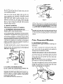
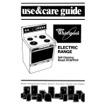
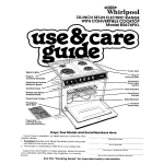
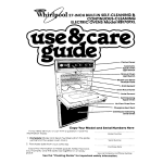
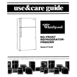
-.
INSTALLATION
INSTRUCTIONS
COMMERCIAL
AUTOMATIC
WASHERS
Proper Hot Water Temperatures
Before you begin,
be sure of . . .
Electrical
Requirements
OBSERVE
ALL GOVERNING
. . .
For best washing,
your water heater should
to the washer
at 1 40° to 160’ Farenheit.
provide
water
STANDARD
BULKHEAD
WIDTH
p 151/4”-j
. . .
CODES
AND
ORDINANCES
A 120 Volt, 60 Hz. AC only, 15 Amp fused electrical
supply
is required
(time delay fuse or circuit
breaker
is recommended).
It is recommended
that a separate circuit serving
only this appliance
be provided.
DO NOT use an extension
Proper Plumbing
cord
. . .
It is essential
to have threaded
faucets
on hot and cold
water outlets
within
4 feet of the water inlets on back of
washer.
Provide a standpipe
with a minimum
diameter
of
2 inches.
Note:
Any suitably
trapped drain having
away capacity
of 17 gallons
per minute
quirements
of the washer.
Proper Drainage
a minimum
will meet
I
P
2”
carrythe re-
Note:
. . .
The drain hose must discharge
into standpipe
at a minimum
height
(from base of the washer)
of 34” and a
maximum
height
of 72”.
It is recommended
that the
washers
be installed
on a concrete
pad 2” above floor level.
The overall
width of a pad in a typical installation
is 69”.
A floor drain should be provided
under the bulkhead.
Prefabricated
bulkheads
with electrical
outlets,
water supply
lines, and drain facilities
should be used only for installations where codes permit.
Proper Water Pressure
Flush Out Water Supply
Lines . . .
Before
installation,
both hot and cold water supply lines
should
be flushed
out to prevent
sediment
in lines from
clogging
screens in washer
water valve. This is especially
important
in new construction.
Now
you
are
to begin . . .
ready
The necessary
installation
parts are packed inside washer
basket
.
. two inlet hoses, one drain hose, two front
leveling feet, two rear leveling
legs, two hose clamps, two
filter screens, four standard hose washers, and one ground
wire assembly.
. . .
A minimum
pressure
of 10 PSI and maximum
pressure
of
100 PSI-dynamic
is recommended
for proper operation.
A pressure
reduction
valve should be used in the supply
line where
inlet pressure
entering
the building
exceeds
100 PSI to prevent damage to the machine
mixing valve. If
pressures
are below
10 PSI-dynamic,
long fill time will
be evident.
Proper
1
tools
. . . no special
tools are needed
in most
you need are such common
tools as a
installations;
all
screwdriver,
pliers,
and adjustable
end wrench.
Just follow these instructions step by step . . .
1. Remove
CAUTION:
Shipping
4. Shipping
Accessories
Do not grasp
console
to move
Accessory
appliance.
After removing
installation
parts from the washer
basket,
re-tape the washer
lid to prevent damage. Lay the washer
on its back, using two packing carton corner supports
for
protection.
Remove the foam plastic shipping
block(3A)
in
the upper left hand corner. (See Figure 1 and 4.)
COLD
SHIPPING
Figure
Removal
. . . Rear
of
appliance
(See Figure
4.)
Remove
the rear service
panel (1)
first remove
two
screws at the bottom of the panel, then swing the panel up
and toward you. Now remove the shipping blocks between
the base plate and cabrnet,
inside the left and right rear
corners
of the washer,
by removinq
the screws,
washers
and plastic spools (2). These assembliesare
for protection
of
the washer during shipping. (See Figure 5.) Push base plate
forward
and remove
the foam plastic
block in the left
corner (38). (See Figure 6.) Save all shipping accessories
in
the event the washer
may be moved to another
location.
HOT
1
2. Rear Leg Assembly
The two rear legs are self-leveling.
from the parts bag.
First
remove
the rear legs
Take one of the rear leveling legs and align the flat portion
of the leg so that it will fit into the hole in the lower
channel of the leveling leg mechanism.
See Figure 2A.
Push up on the
Figure 26.
leveling
leg until
it snaps
in place.
See
Figure 28
Figure 2A
Repeat the previous
steps with the remaining
rear leveling
leg. Then push up on one of the rear leveling legs. The other
leg should go down. Next, push up on the leg that is down.
This leg should move up and the one that was up should
move down.
If the leveling
legs are not working
properly,
recheck to make sure you have followed
the instructions.
3. Front Leg Assembly
(See Figure
3.)
By hand, turn each of the front leveling
legs half way(up
to
the diamond
marking on the threads) into the front cabinet
gussets.
Liquid detergent
can be used to reduce the force
needed to turn the legs into the gussets.
Some legs may
require
the use of a suitable
hand tool for installation.
Note: Do not use oil or grease
Now
stand
washer
23 -g
J
upright.
..’
I
/
WASHER BACK
Figure 3
&d-&“lCE
Figure 4
2
hgure
8
Figure 5
If necessary, shorten discharge hose (10) by cutting to
fit installation. Avoid stretching or kinking. Also double
check the internal drain hose (23) to make sure that
it is not twisted or kinked. Be sure hose is secured to
drain pipe and that it is above the normal water level
of the washer to prevent siphoning. (Minimum height
34 inches, maximum height 72 inches from the base
of the washer.)
Note:
Under
no crrcumstances
connected
drrectly to the dram
break IS provrded In accordance
BE CAREFUL
Now
replace
NOT
may the drain hose be
unless an adequate
siphon
wrth local plumbrng
codes
TO TWIST
OR KINK
ANY
HOSES
that
came with
the rear servrce panel
Frgure 6
6.
Hot
Water
Hose
Assembly
Be sure to use the new hoses and washers
your new Whirlpool
Washer.
5. Drain Hose Assembly (See Figure 4 & 7)
From the inside, place plain end (no tabs) of the angle
connector (8) through the lower hole in cabinet and
snap in place. Position the angle connector from outside to face the standpipe. (See Figure 7.) Next, place
the smaller hose clamp (9) on the internal drain hose
(23). Remove plug from inside hose, then place the
hose on the angle connector. Secure with hose clamp.
Place the larger hose clamp (6) on the discharge hose
tO8))and place on the angle connector. (See Figure 4
Film
Insert one of the flat hose washers
(14) and (16) into
each end of one of the inlet hoses (See Figure 9). BE
SURE
WASHERS
ARE SECURELY
SEATED
IN HOSE
COUPLINGS.
Attach one end of this hose (13) to the hot
water
faucet
(17). Tighten
coupling
hand-tight,
then an
additional
two-thirds
turn with pliers. Attach the other end
of the inlet hose (13) to the bottom
port of the inlet valve
(See “H” mark on cabinet for hot) (15). Tighten coupling
hand-tight,
then an additional
two-thirds
turn with pliers.
DO NOT CROSS THREAD.
7
3
EXTERNAL
GROUND
WER SUPPLY
GROUNDED
COI LO
WATER
PIPE
IREMOVE
PAIN1 ‘, ETC.)
7. Cold Water Hose Assembly
Be sure to use the new hoses and washers
your new Whirlpool
Washer.
that
came with
Insert one of the flat hose washers
(19) and (21) into
each end of one of the inlet hoses (See Figure 9). BE
SURE WASHERS
ARE SECURELY
SEATED
IN HOSE
COUPLINGS.
Attach one end of this hose (18) to the cold
water
faucet
(22). Tighten
coupling
hand-tight,
then an
additional
two-thirds
turn with pliers. Attach
the other
end of the inlet hose (18) to the top port of the inlet valve
(See “C” mark on cabinet for cold) (20). Tighten coupling
hand-tight,
then an additional
two-thirds
turn with pliers.
DO NOT CROSS THREAD.
8. Electrical
Electrical
IN0
is required
on this
* Grounded
cold water pipe must have metal continuity
to
electrical
ground and not be interrupted
by plastic, rubber
or other electrically
insulating
connectors
(including
water
meter or pump) without
adding a jumper wire at these connections.
THE
For your personal
safety, this appliance
must be grounded.
This appliance
is equipped
with a power supply cord having
a 3-prong ground plug. To minimize
possible shock hazard,
the cord must be plugged Into a mating 3-prong grounding
type wall receptacle,
grounded
in accordance
with the
National
Electrical
Code and local codes and ordinances.
If
a mating wall receptacle
is not available,
it is the personal
responslblllty
and obligation
of the customer
to have a
properly
grounded
3-prong
wall receptacle
installed
by a
qualified
electriclan.
(See Figure 10 ).
Coin Operated
9.
Mechanism
power
Models
Information
supply
cord before
installing
coin
This washer is equipped
with a meter case console, timer,
selector switches and indicator
lights. The coin slide mechanism, service lock and vault assembly can be supplied
by
the same source that supplied this washer.
J-PRONG
GROUNDING
TYPE
WALL
RECEPTACLE
POWER
CORD
Coin
Disconnect
mechanism.
For added personal
safety,
using the clamp and green
colored
copper
wire
furnished,
connect
this separate
ground
wire (No. 18 minlmum)
from the external
ground
connector
on the back of the appliance
to a grounded
cold
wa Ite!r pipe’. (See Figure 11 .)
3-PRONG
GROUNDING
PLUG
11
If this is done, you must connect a separate copper ground
wire (No. 18 minimum)
to a grounded cold water pipe* by
means of a clamp and then to the external ground connector
screw. Do not ground to a gas supply pipe. Do not connect
to electrical
supply until appliance is permanently
grounded.
appliance.
A. RECOMMENDED
GROUNDING
METHOD
DO NOT, UNDER ANY CIRCUMSTANCES,
REMOVE
POWER SUPPLY CORD GROUND
PRONG.
GROUND
CLAMP
MUST BE TIGHT
ON PIPE
Figure
Connections
ground
WIRE
18 MlNlMUMl
install
the slide extension
to the coin slide mechanism.
To install the coin slide mechanism,
remove the service
door of the meter case. Lift the meter case top up at the
back to remove. Carefully
insert coin slide mechanism
into
opening
and secure with the 3/16” bolt from inside meter
case. (See Figure 12.)
Note: The coin slide may have to be pushed in partially
to
gain clearance to install the coin slide mechanism.
\
SUPPLY
Figure
This model is equipped
with a security
top lock concealed
under the top, inside the meter case. Access to the lock is
through
the service
door of the meter case. (See insert
sheet for concealed
top lock information.)
10
B. ALTERNATE
GROUNDING
METHOD
DO NOT, UNDER ANY CIRCUMSTANCES,
POWER SUPPLY CORD GROUND
PRONG.
REMOVE
THE
If changing
and properly
grounding
the wall receptacle
is
impossible
and where
local codes permit
(consult
your
elecirical
inspector),
a temporary
adapter
may be plugged
into the existing
2-prong
wall receptacle
to mate with the
3-prong
power supply cord.
THIS, HOWEVER,
IS NOT RECOMMENDED.
Figure 12
4
Non-Coin Operated Models
10.
Operation
For all models, level washer from front to rear and from side
to side by adjusting
the front leveling feet until the water is
level with the bottom row of holes around the basket.
Information
This washer is equipped with
selector switches and indicator
a console,
lights.
The rear legs are self-leveling
and adjusted
by tilting
the
washer forward
and up approximately
1” in the rear, then
releasing the washer so that the rear legs can settle themselves to a level position.
push to start timer,
The timer has a 9-l/2 minute wash cycle and can be operated
manually,
for service, from the rear of the console.
The
timer cycle information
is ink stamped on the rear of the
timer, a lever is attached to the rear of the timer shaft to
manually
position the timer through the cycle.
12.
Timer Clutch
Adjustment
(If needed)
All coin operated
models have a timer that has a 9-l/2
minute wash in the Normal cycle. During the cycle check,
actuate the coin mechanism
and then check the wash cycle
time. If the washer fails to start or does not give the proper
wash cycle time, the clutch assembly may need adjustment
as follows:
To change cycle position,
first stop the washer by pushing
in on the lever from the rear, then reset lever to new cycle
position and pull to restart the washer. (See Figure 13.)
Note: The clutch assembly is equipped
with a timer clutch
adjustment
screw. To adjust the adjustment
screw, remove
the timer from the meter case and adjust the timer clutch
adjustment
screw as follows:
A. If the appliance
fails to start after the coin slide mechanism has been fully actuated
IN or OUT, a CLOCK-WISE
adjustment
of the screw is indicated.
(See Figure 15.)
B. If the appliance
timer goes past the third increment
of
fill (less than 9-l/2
minutes of wash will occur in Normal
cycle),
turn
the adjustment
screw
COUNTER-CLOCKWISE. (See Figure 15.)
TIMER-REAR
Figure
11. Leveling
VIEW
13
Your Washer (All models)
Now move the washer
to its permanent
operating
location.
Turn on the faucets
and check for leaks, then fill the
washer
with water up to the bottom row of holes around
the basket.
Note: On coin operated
models the timer may be turned by
using the clutch
assembly
as a knob.
Rotate
the clutch
assembly
counter-clockwise
until
the washer starts to fill
with water. When the proper water level is reached, slowly
rotate
the clutch
assembly
counter-clockwise
until
the
“off”
position
is reached. (See Figure 14.)
ROTATE
COUNTERCLOCKWISE
ONLY
\
Figure
13.
J
-TIMER
Figure
15
Make a Cycle Check (All models)
Refer to the operating
instructions
and run the washer
through
one complete
cycle. For coin-operated
models the
washer maybe operated
manuallyascovered
in the second
paragraph
under “Leveling
Your Washer.”
Use one-half
the recommended
amount
of detergent.
After the cycle,
check all hoses and water connections
to see that they are
operating
properly
and that they do not leak.
FF”
4
TIMER
CLUTCH
ADJUSTMENT
SCREW
FRONT
14
5
-.
Important
Information
1. Make sure
proper electrical
are blown.
Operating
the power
supply cord IS plugged
In and
contact made Check fuses to be sure none
2. Make
sure
timer
has been
3.
Make
sure
water
faucets
4.
Make
sure
rnlet
and dram
5. The washer
6. Excess suds cause “Suds Lock” slow sprn, and poor
rtnsing. If sptnmng IS slow and excess suds are present, run
the washer
through
a complete
cycle without
usng detergent. On future
loads use less detergent
or a controlled
suds type detergent
advanced
to start
are turned
hoses
7. It IS recommended
that fiberglass
In cotn-operated
washers
If these type
the washer,
the washer
must be run
cycle to rtnse away any residue
that
washer
from ftberglass
Items
cycle
on
are
not
Items not be washed
rtemsare
washed in
through
a complete
might be left In the
Do not use drycleaning
flurds
8. CAUTION
mable solvents
In the automatic
washer
ktnked
or other
WIII not sptn 11 Ird IS open
9.
Special
Reminder
Plan to place your
Its Inlet valve IS protected
from freezrng
This
chart
gives
examples
of typical
full
washer
loads
,j
LOAD TYPE
LOADING
Mixed
2
4
6
6
2
2
6
Load
Permanent
Press
SUGGESTION
double or 1 king size sheet
pillowcases
T-shirts
pair shorts
shirts
blouses
handkerchiefs
1 double sheet
1 tablecloth
3 shirts
1 dress
1 blouse
2 slacks
2 pillowcases
This washer
provides
cold water rinses,
washer to provide warm water rinses:
washer
from
electrical
rear panel and
insulated
terminal
3. Install
switch.
wire
4. Reassemble
console
to terminal
convert
this
supply.
2. Remove
console
red wire with
the
harness.
brown-red
to
untape
from
the brownthe console
J2 on cycle
LOAD TYPE
Heavy
Knits
Instructions
for Converting
from Cold Water Rinses
to Warm Water Rinses
1. Disconnect
flam-
selection
rear panel.
6
work
clothes
LOADING
SUGGESTION
2
3
1
3
pair work pants
work shirts
coverall
pair jeans
2 slacks
6 tops
4 shirts
2 dresses
where
Moving Operations
Procedure
1. Turn
off both
2. Start
the washer
3. Turn
off the washer.
4. Remove power
rear of machine.
5. Remove
inlet
6. Remove Inlet
and place hoses
7. Remove
KINK )
drain
8. Lay washer
they are flush
water
9. Pull downward
on each of the rear
they are free of the leveling foot channel.
faucets.
in the fill portion
plastic foam
1 and 6 (3A & 36).
hoses
from
hoses from
In basket.
hose,
wall
socket,
coil and tape
hot and cold water
water
inlet
valve.
to
faucets.
Wrap
in upright
12. Remove
servrce
13. Install
ends
coil and place
on Its back and turn front
with cabrnet.
In basket
(DO NOT
levelrng
feet until
Showing
15. Tape
rear
nylon
spool
rear
and bolts
MINIMUM
NOTE: Upon reinstallation
and screen washers
with
.---I-----------
\\I
(2). Figure
is now
ready
of machine,
new.
Typical
I!
5
for shipment
replace
COPPER GROUND
WIRE (NO. 18 MINIMUM)
INLET
1
-
I
4
hose assembly must fit in the standpipe
so that there is an air gap around
hose inside the standpipe.
A snug fit can cause a siphoning
action.
FOR COMPLETE SERVICE
WHIRLPOOL
COMMERCIAL
used hose
Assembly
ET
* The drain
drain
(Do notgraspconsole.)
1
COLD WATER INLET
L F,, HOT WATER INLET
DRAIN*
2” MINiiiiUM/
’
STANDPIPE
I
t FOR 1 MACHINEA
in Figures
12” MINIMUM
I,
I I
as shown
panel
\ ELECTRICAL
34”
72”
until
panel
Washer
ON SINGLE UNIT OPERATION
INSTALLATIONS
USE RISER TO
PREVENT AIR HAMMER. IT SHOULD
BE OF SAME SIZE PIPE AS OUTLET.
RISER PROVIDES AN AIR CUSHION
WHICH PREVENTS NOISE AND
DAMAGE TO VALVES.
blocks
position.
servrce
lid closed
Complete
120 VOLT, 3-PRONG
RECEPTACLE (15 AMP)
shipping
11. Place washer
14. Reinstall
Illustration
feet
of the wash cycle.
10. Replace
cord from
leveling
INFORMATION,
AUTOMATIC
7
the
BE SURE TO READ THE
WASHER SERVICE MANUAL
Benlon Harbor. Michigan. Aulomalic Washers. Clolhes Dryers.
Freezers. Relrigeralor-Freezers.
Ice Makers. Dishwashers.
Buill-in Ovens and Surlace Units. Ranges. Microwave Ovens.
Compactors. Room Air Condilioners. Oehumidiliers.
Cenlral
Healing and Air Conditioning Systems.
Quality. Our way of life.
Part No. 372073 Rev. A
PrInted
8
I” U S A