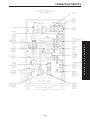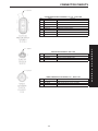
1
TABLE OF CONTENTS
1.0
INTRODUCTION . . . . . . . . . . . . . . . . . . . . . . . . . . . . . . . . . . . . . . . . . . . . . . . . . . . . . . . . .1
1.1
1.2
SYSTEM COVERAGE . . . . . . . . . . . . . . . . . . . . . . . . . . . . . . . . . . . . . . . . . . . . . . .1
SIX -STEP TROUBLESHOOTING PROCEDURE . . . . . . . . . . . . . . . . . . . . . . . . . .1
2.0
IDENTIFICATION OF SYSTEM . . . . . . . . . . . . . . . . . . . . . . . . . . . . . . . . . . . . . . . . . . . . .1
3.0
SYSTEM DESCRIPTION AND FUNCTIONAL OPERATION . . . . . . . . . . . . . . . . . . . . . .1
3.1
3.2
3.3
3.4
3.5
3.6
4.0
GENERAL DESCRIPTION . . . . . . . . . . . . . . . . . . . . . . . . . . . . . . . . . . . . . . . . . . . .1
FUNCTIONAL OPERATION . . . . . . . . . . . . . . . . . . . . . . . . . . . . . . . . . . . . . . . . . . .1
3.2.1 AUTOSTICK FEATURE . . . . . . . . . . . . . . . . . . . . . . . . . . . . . . . . . . . . . . .1
3.2.2 TRANSMISSION OPERATION AND SHIFT SCHEDULING AT
VARIOUS OIL TEMPERATURES. . . . . . . . . . . . . . . . . . . . . . . . . . . . . . . .2
DIAGNOSTIC TROUBLE CODES . . . . . . . . . . . . . . . . . . . . . . . . . . . . . . . . . . . . . .3
3.3.1 HARD CODE . . . . . . . . . . . . . . . . . . . . . . . . . . . . . . . . . . . . . . . . . . . . . . . .3
3.3.2 ONE TRIP FAILURES . . . . . . . . . . . . . . . . . . . . . . . . . . . . . . . . . . . . . . . . .3
3.3.3 INTERMITTENT CODE. . . . . . . . . . . . . . . . . . . . . . . . . . . . . . . . . . . . . . . .3
3.3.4 STARTS SINCE SET COUNTER. . . . . . . . . . . . . . . . . . . . . . . . . . . . . . . .3
3.3.5 TROUBLE CODE ERASURE . . . . . . . . . . . . . . . . . . . . . . . . . . . . . . . . . . .4
3.3.6 LIST OF DIAGNOSTIC TROUBLE CODES. . . . . . . . . . . . . . . . . . . . . . . .4
3.3.7 DTC DESCRIPTIONS . . . . . . . . . . . . . . . . . . . . . . . . . . . . . . . . . . . . . . . . .5
3.3.8 QUICK LEARN . . . . . . . . . . . . . . . . . . . . . . . . . . . . . . . . . . . . . . . . . . . . .16
3.3.9 CLUTCH VOLUMES . . . . . . . . . . . . . . . . . . . . . . . . . . . . . . . . . . . . . . . . .17
3.3.10 ELECTRONIC PINION FACTOR . . . . . . . . . . . . . . . . . . . . . . . . . . . . . . .17
USING THE DRBIIIT . . . . . . . . . . . . . . . . . . . . . . . . . . . . . . . . . . . . . . . . . . . . . . . .18
DRBIIIT ERROR MESSAGES . . . . . . . . . . . . . . . . . . . . . . . . . . . . . . . . . . . . . . . .18
3.5.1 DRBIIIT DOES NOT POWER UP (BLANK SCREEN). . . . . . . . . . . . . . .18
3.5.2 DISPLAY IS NOT VISIBLE . . . . . . . . . . . . . . . . . . . . . . . . . . . . . . . . . . . .18
TRANSMISSION SIMULATOR (MILLER TOOL # 8333) AND
FWD ADAPTER (MILLER TOOL #8333-1) . . . . . . . . . . . . . . . . . . . . . . . . . . . . . .18
DISCLAIMERS, SAFETY, AND WARNINGS . . . . . . . . . . . . . . . . . . . . . . . . . . . . . . . . .18
4.1
4.3
DISCLAIMERS. . . . . . . . . . . . . . . . . . . . . . . . . . . . . . . . . . . . . . . . . . . . . . . . . . . . .18
4.2.1 TECHNICIAN SAFETY INFORMATION . . . . . . . . . . . . . . . . . . . . . . . . . .19
4.2.2 VEHICLE PREPARATION FOR TESTING. . . . . . . . . . . . . . . . . . . . . . . .19
4.2.3 SERVICING SUB-ASSEMBLIES . . . . . . . . . . . . . . . . . . . . . . . . . . . . . . .19
4.2.4 DRBIIIT SAFETY INSTRUCTIONS . . . . . . . . . . . . . . . . . . . . . . . . . . . . .19
WARNINGS . . . . . . . . . . . . . . . . . . . . . . . . . . . . . . . . . . . . . . . . . . . . . . . . . . . . . . .20
4.3.1 VEHICLE DAMAGE WARNINGS . . . . . . . . . . . . . . . . . . . . . . . . . . . . . . .20
4.3.2 ROAD TEST COMPLAINT VEHICLE . . . . . . . . . . . . . . . . . . . . . . . . . . . .20
4.3.3 ELECTRONIC PINION FACTOR WARNINGS. . . . . . . . . . . . . . . . . . . . .20
4.3.4 BULLETINS AND RECALLS. . . . . . . . . . . . . . . . . . . . . . . . . . . . . . . . . . .20
5.0
REQUIRED TOOLS AND EQUIPMENT . . . . . . . . . . . . . . . . . . . . . . . . . . . . . . . . . . . . .20
6.0
GLOSSARY OF TERMS. . . . . . . . . . . . . . . . . . . . . . . . . . . . . . . . . . . . . . . . . . . . . . . . . .21
6.1
6.2
7.0
ACRONYMS . . . . . . . . . . . . . . . . . . . . . . . . . . . . . . . . . . . . . . . . . . . . . . . . . . . . . .21
DEFINITIONS . . . . . . . . . . . . . . . . . . . . . . . . . . . . . . . . . . . . . . . . . . . . . . . . . . . . .21
DIAGNOSTIC INFORMATION AND PROCEDURES . . . . . . . . . . . . . . . . . . . . . . . . . . .23
i
TABLE OF CONTENTS - Continued
TRANSMISSION
P0120-THROTTLE POSITION SENSOR SIGNAL CIRCUIT . . . . . . . . . . . . . . . . . . . . .24
P0600-SERIAL COMMUNICATION LINK MALFUNCTION . . . . . . . . . . . . . . . . . . . . . . .26
P0604-INTERNAL TCM . . . . . . . . . . . . . . . . . . . . . . . . . . . . . . . . . . . . . . . . . . . . . . . . . .28
P0605-INTERNAL TCM . . . . . . . . . . . . . . . . . . . . . . . . . . . . . . . . . . . . . . . . . . . . . . . . . .29
P0700-INTERNAL TCM . . . . . . . . . . . . . . . . . . . . . . . . . . . . . . . . . . . . . . . . . . . . . . . . . .30
P0705-CHECK SHIFTER SIGNAL . . . . . . . . . . . . . . . . . . . . . . . . . . . . . . . . . . . . . . . . . .31
P0715-INPUT SPEED SENSOR ERROR . . . . . . . . . . . . . . . . . . . . . . . . . . . . . . . . . . . .38
P0720-OUTPUT SPEED SENSOR ERROR . . . . . . . . . . . . . . . . . . . . . . . . . . . . . . . . . .42
P0725-ENGINE SPEED SENSOR CIRCUIT (3.3L/3.8L) . . . . . . . . . . . . . . . . . . . . . . . .46
P0725-ENGINE SPEED SENSOR CIRCUIT (3.5L) . . . . . . . . . . . . . . . . . . . . . . . . . . . .48
P0731-GEAR RATIO ERROR IN 1ST . . . . . . . . . . . . . . . . . . . . . . . . . . . . . . . . . . . . . . .51
P0732-GEAR RATIO ERROR IN 2ND . . . . . . . . . . . . . . . . . . . . . . . . . . . . . . . . . . . . . . .53
P0733-GEAR RATIO ERROR IN 3RD . . . . . . . . . . . . . . . . . . . . . . . . . . . . . . . . . . . . . . .55
P0734-GEAR RATIO ERROR IN 4TH . . . . . . . . . . . . . . . . . . . . . . . . . . . . . . . . . . . . . . .57
P0736-GEAR RATIO ERROR IN REVERSE . . . . . . . . . . . . . . . . . . . . . . . . . . . . . . . . . .59
P0740-TORQUE CONVERTER CLUTCH CONTROL CIRCUIT. . . . . . . . . . . . . . . . . . .61
P0750-LR SOLENOID CIRCUIT. . . . . . . . . . . . . . . . . . . . . . . . . . . . . . . . . . . . . . . . . . . .63
P0755-2-4 SOLENOID CIRCUIT . . . . . . . . . . . . . . . . . . . . . . . . . . . . . . . . . . . . . . . . . . .66
P0760-OD SOLENOID CIRCUIT . . . . . . . . . . . . . . . . . . . . . . . . . . . . . . . . . . . . . . . . . . .69
P0765-UD SOLENOID CIRCUIT . . . . . . . . . . . . . . . . . . . . . . . . . . . . . . . . . . . . . . . . . . .72
P1714-LOW BATTERY VOLTAGE . . . . . . . . . . . . . . . . . . . . . . . . . . . . . . . . . . . . . . . . . .75
P1716-BUS COMMUNICATION WITH PCM . . . . . . . . . . . . . . . . . . . . . . . . . . . . . . . . . .79
P1717-NO COMMUNICATION WITH THE MIC . . . . . . . . . . . . . . . . . . . . . . . . . . . . . . .81
P1738-HIGH TEMPERATURE OPERATION ACTIVATED . . . . . . . . . . . . . . . . . . . . . . .83
P1739-POWER UP AT SPEED . . . . . . . . . . . . . . . . . . . . . . . . . . . . . . . . . . . . . . . . . . . .85
P1765-SWITCHED BATTERY . . . . . . . . . . . . . . . . . . . . . . . . . . . . . . . . . . . . . . . . . . . . .86
P1767-TRANSMISSION RELAY ALWAYS ON . . . . . . . . . . . . . . . . . . . . . . . . . . . . . . . .89
P1768-RELAY OUTPUT ALWAYS OFF . . . . . . . . . . . . . . . . . . . . . . . . . . . . . . . . . . . . . .92
P1775-SOLENOID SWITCH VALVE LATCHED IN TCC POSITION . . . . . . . . . . . . . . .96
P1776-SOLENOID SWITCH VALVE LATCHED IN LR POSITION. . . . . . . . . . . . . . . .100
P1781-OD PRESSURE SWITCH SENSE CIRCUIT . . . . . . . . . . . . . . . . . . . . . . . . . . .104
P1782 - 2-4 PRESSURE SWITCH SENSE CIRCUIT . . . . . . . . . . . . . . . . . . . . . . . . . .107
P1784-LR PRESSURE SWITCH SENSE CIRCUIT . . . . . . . . . . . . . . . . . . . . . . . . . . .110
P1787-OD HYDRAULIC PRESSURE TEST FAILURE . . . . . . . . . . . . . . . . . . . . . . . . .114
P1788-2/4 HYDRAULIC PRESSURE TEST FAILURE . . . . . . . . . . . . . . . . . . . . . . . . .118
P1789-2-4/OD HYDRAULIC PRESSURE TEST FAILURE . . . . . . . . . . . . . . . . . . . . . .122
P1790-FAULT IMMEDIATELY AFTER SHIFT . . . . . . . . . . . . . . . . . . . . . . . . . . . . . . . .123
P1791-LOSS OF PRIME. . . . . . . . . . . . . . . . . . . . . . . . . . . . . . . . . . . . . . . . . . . . . . . . .124
P1792-BATTERY WAS DISCONNECTED . . . . . . . . . . . . . . . . . . . . . . . . . . . . . . . . . . .127
P1793-TRD LINK COMMUNICATION ERROR . . . . . . . . . . . . . . . . . . . . . . . . . . . . . . .130
P1794-SPEED SENSOR GROUND ERROR . . . . . . . . . . . . . . . . . . . . . . . . . . . . . . . .133
P1795-INTERNAL TCM . . . . . . . . . . . . . . . . . . . . . . . . . . . . . . . . . . . . . . . . . . . . . . . . .135
P1796-AUTOSTICK SENSOR CIRCUIT . . . . . . . . . . . . . . . . . . . . . . . . . . . . . . . . . . . .136
P1797-MANUAL SHIFT OVERHEAT . . . . . . . . . . . . . . . . . . . . . . . . . . . . . . . . . . . . . . .139
P1798-WORN OUT/BURNT TRANSAXLE FLUID. . . . . . . . . . . . . . . . . . . . . . . . . . . . .140
P1799-CALCULATED OIL TEMP IN USE . . . . . . . . . . . . . . . . . . . . . . . . . . . . . . . . . . .142
*BRAKE SHIFT INTERLOCK OUTPUT OPEN . . . . . . . . . . . . . . . . . . . . . . . . . . . . . . .146
*CHECKING PARK/NEUTRAL SWITCH OPERATION . . . . . . . . . . . . . . . . . . . . . . . . .148
*INCORRECT TRANSMISSION FLUID LEVEL. . . . . . . . . . . . . . . . . . . . . . . . . . . . . . .150
*NO BACK UP LAMP OPERATION . . . . . . . . . . . . . . . . . . . . . . . . . . . . . . . . . . . . . . . .151
*NO SPEEDOMETER OPERATION. . . . . . . . . . . . . . . . . . . . . . . . . . . . . . . . . . . . . . . .153
*TRANSMISSION NOISY WITH NO DTC’S PRESENT . . . . . . . . . . . . . . . . . . . . . . . .154
ii
TABLE OF CONTENTS - Continued
*TRANSMISSION SHIFTS EARLY WITH NO DTC’S . . . . . . . . . . . . . . . . . . . . . . . . . .155
*TRANSMISSION SIMULATOR 8333 WILL NOT POWER UP . . . . . . . . . . . . . . . . . .156
VERIFICATION TESTS
VERIFICATION TESTS . . . . . . . . . . . . . . . . . . . . . . . . . . . . . . . . . . . . . . . . . . . . . . . . . .157
8.0
COMPONENT LOCATIONS . . . . . . . . . . . . . . . . . . . . . . . . . . . . . . . . . . . . . . . . . . . . . .159
8.1
8.2
8.3
8.4
8.5
8.6
8.7
9.0
POWERTRAIN CONTROL MODULE. . . . . . . . . . . . . . . . . . . . . . . . . . . . . . . . . .159
TRANSMISSION CONTROL MODULE . . . . . . . . . . . . . . . . . . . . . . . . . . . . . . . .159
INTELLIGENT POWER MODULE . . . . . . . . . . . . . . . . . . . . . . . . . . . . . . . . . . . .159
PRESSURE PORT LOCATIONS . . . . . . . . . . . . . . . . . . . . . . . . . . . . . . . . . . . . .160
THROTTLE POSITION SENSOR (2.4L) . . . . . . . . . . . . . . . . . . . . . . . . . . . . . . .160
AUTOSTICK/OD OFF . . . . . . . . . . . . . . . . . . . . . . . . . . . . . . . . . . . . . . . . . . . . . .160
TRANSMISSION COMPONENT LOCATIONS . . . . . . . . . . . . . . . . . . . . . . . . . .161
CONNECTOR PINOUTS . . . . . . . . . . . . . . . . . . . . . . . . . . . . . . . . . . . . . . . . . . . . . . . .163
AUTOSTICK SWITCH - BLACK 2 WAY. . . . . . . . . . . . . . . . . . . . . . . . . . . . . . . . . . . . .163
BODY CONTROL MODULE C2 - BLACK/GREEN 34 WAY . . . . . . . . . . . . . . . . . . . . .163
BRAKE LAMP SWITCH - BLACK 6 WAY . . . . . . . . . . . . . . . . . . . . . . . . . . . . . . . . . . .164
CRANKSHAFT POSITION SENSOR - BLACK 3 WAY . . . . . . . . . . . . . . . . . . . . . . . . .164
DATA LINK CONNECTOR - WHITE 16 WAY . . . . . . . . . . . . . . . . . . . . . . . . . . . . . . . .164
DIAGNOSTIC JUNCTION PORT - BLACK 16 WAY . . . . . . . . . . . . . . . . . . . . . . . . . . .165
INPUT SPEED SENSOR (3.3L/3.8L) - GRAY 2 WAY . . . . . . . . . . . . . . . . . . . . . . . . . .165
INTELLIGENT POWER MODULE C3 - NATURAL 20 WAY . . . . . . . . . . . . . . . . . . . . .165
INTELLIGENT POWER MODULE C4 - GRAY 10 WAY . . . . . . . . . . . . . . . . . . . . . . . .166
INTELLIGENT POWER MODULE C5 - BLACK 4 WAY . . . . . . . . . . . . . . . . . . . . . . . .166
INTELLIGENT POWER MODULE C6 - WHITE 10 WAY . . . . . . . . . . . . . . . . . . . . . . .166
INTELLIGENT POWER MODULE C7 - BLACK 20 WAY . . . . . . . . . . . . . . . . . . . . . . .167
INTELLIGENT POWER MODULE C9 - BLACK 10 WAY . . . . . . . . . . . . . . . . . . . . . . .167
LEFT REAR LAMP ASSEMBLY - BLACK 6 WAY . . . . . . . . . . . . . . . . . . . . . . . . . . . . .167
OUTPUT SPEED SENSOR (3.3L/3.8L) - GRAY 2 WAY . . . . . . . . . . . . . . . . . . . . . . . .168
PARK/NEUTRAL POSITION SWITCH (2.4L) - BLACK 3 WAY . . . . . . . . . . . . . . . . . .168
FUSES (IPM) . . . . . . . . . . . . . . . . . . . . . . . . . . . . . . . . . . . . . . . . . . . . . . . . . . . . . . . . . .170
TRANSMISSION SAFETY SHUTDOWN RELAY . . . . . . . . . . . . . . . . . . . . . . . . . . . . .170
POWERTRAIN CONTROL MODULE C1 - GRAY/BLACK 40 WAY . . . . . . . . . . . . . . .171
POWERTRAIN CONTROL MODULE C2 - GRAY/GRAY 40 WAY . . . . . . . . . . . . . . . .172
RIGHT REAR LAMP ASSEMBLY - BLACK 6 WAY . . . . . . . . . . . . . . . . . . . . . . . . . . . .172
SOLENOID/PRESSURE SWITCH ASSEMBLY (3.3L/3.8L) - BLACK 8 WAY . . . . . . .173
THROTTLE POSITION SENSOR - GRAY 3 WAY . . . . . . . . . . . . . . . . . . . . . . . . . . . .173
TORQUE CONVERTER CLUTCH SOLENOID (2.4L) - BLACK 3 WAY . . . . . . . . . . .173
TRANSMISSION CONTROL MODULE (3.3L/3.8L) - BLACK 60 WAY . . . . . . . . . . . .174
TRANSMISSION RANGE SENSOR (3.3L/3.8L) - GRAY 10 WAY . . . . . . . . . . . . . . . .175
10.0
SCHEMATIC DIAGRAMS. . . . . . . . . . . . . . . . . . . . . . . . . . . . . . . . . . . . . . . . . . . . . . . .177
iii
NOTES
iv
GENERAL INFORMATION
1.0
INTRODUCTION
3.0
The procedures contained in this manual include
all of the specifications, instructions, and graphics
needed to diagnose 41TE/AE Electronic Automatic
Transaxle (EATX) problems. The diagnostics in this
manual are based on the failure condition or symptom being present at the time of diagnosis.
When repairs are required, refer to the appropriate volume of the service manual for the proper
removal and repair procedure.
Diagnostic procedures change every year. New
diagnostic systems may be added and/or carryover
systems may be enhanced. READ THIS MANUAL
BEFORE TRYING TO DIAGNOSE A VEHICLE
TROUBLE CODE. It is recommended that you
review the entire manual to become familiar with
all new and changed diagnostic procedures.
This book reflects many suggested changes from
readers of past issues. After using this book, if you
have any comments or recommendations, please fill
out the form at the back of the book and mail it back
to us.
1.1
3.1
3.2
FUNCTIONAL OPERATION
The 41TE/AE electronic transaxle has a fully
adaptive control system. The system performs it’s
functions based on continuous real-time sensor
feedback information. The control system automatically adapts to changes in engine performance and
friction element variations to provide consistent
shift quality. The control system ensures that clutch
operation during upshifting and downshifting is
more responsive without increased harshness.
The Transmission Control Module (TCM) continuously checks for electrical problems, mechanical
problems, and some hydraulic problems. When a
problem is sensed, the TCM stores a diagnostic
trouble code. Some of these codes cause the transaxle to go into limp-in or default mode.
While in this mode, electrical power is taken
away from the transaxle via the TCM, deenergizing the transmission control relay, and taking power from the solenoid pack. When this happens, the only transaxle mechanical functions are:
Park and Neutral
Reverse
Second Gear
No upshifts or downshifts are possible. The position of the manual valve alone allows the three
ranges that are available. Although vehicle performance is seriously degraded while in this mode, it
allows the owner to drive the vehicle in for service.
Once the DRBIIIt is in the EATX portion of the
diagnostic program, it constantly monitors the
TCM to see if the system is in limp-in mode. If the
transaxle is in limp-in mode, the DRBIII® will flash
the red LED.
SYSTEM COVERAGE
SIX -STEP TROUBLESHOOTING
PROCEDURE
Diagnosis of the 41TE/AE electronic transaxle is
done in six basic steps:
verification of complaint
verification of any related symptoms
symptom analysis
problem isolation
repair of isolated problem
verification of proper operation
2.0
GENERAL DESCRIPTION
The 41TE/AE electronic transaxle is a conventional transaxle in that it uses hydraulically applied clutches to shift a planetary gear train. However, the electronic control system replaces many of
the mechanical and hydraulic components used in
conventional transmission valve bodies.
This diagnostic procedures manual covers all
2001 RG equipped with a 41TE/AE transaxle.
1.2
SYSTEM DESCRIPTION AND
FUNCTIONAL OPERATION
IDENTIFICATION OF
SYSTEM
RG series vehicles equipped with a 4 speed transmission.
3.2.1
AUTOSTICK FEATURE
This feature allows the driver to manually shift
the transaxle when the shift lever is pulled back
into the AutoStick position. When in AutoStick
mode, the instrument cluster displays the current
gear.
1
GENERAL INFORMATION
3.2.2
TRANSMISSION OPERATION AND
SHIFT SCHEDULING AT VARIOUS
OIL TEMPERATURES.
> High speed 4-2, 3-2, 2-1 kickdown shifts are
prevented
> No EMCC
Warm: Oil temperature at start up above 2.2C
(36°F) and below 27C (80°F)
The transmission covered in this manual has
unique shift schedules depending on the temperature of the transmission oil. The shift schedule is
modified to extend the life of the transmission while
operating under extreme conditions.
The oil temperature is measured with a Temperature Sensor on the 41TE/AE transmission. The
Temperature Sensor is an integral component of the
Transmission Range Sensor (TRS). If the Temperature Sensor is faulty, (DTC P1799(74)) the transmission will default to a calculated oil temperature.
Oil temperature will then be calculated through a
complex heat transfer equation which uses engine
coolant temperature, battery/ambient temperature,
and engine off time from the Body Control Module
(BCM). These inputs are received from the PCI bus
periodically and used to initialize the oil temperature at start up. Once the engine is started, the
TCM updates the transmission oil temperature
based on torque converter slip speed, vehicle speed,
gear, and engine coolant temperature to determine
an estimated oil temperature during vehicle operation. Vehicles using a calculated oil temperature
track oil temperature reasonably accurate during
normal operation. However, if a transmission is
overfilled, a transmission oil cooler becomes restricted, or if a customer drives aggressively in low
gear, the calculated oil temperature will be inaccurate. Consequently the shift schedule selected may
be inappropriate for the current conditions. The key
highlights of the various shift schedules are as
follows:
Extreme Cold: Oil temperature at start up below
-26.6C (-16°F)
> Goes to a Cold schedule above -24C (-12°F) oil
temperature
> Goes to a Hot schedule above 27C (80°F) oil
temperature
> Normal operation (upshifts, kickdowns, and
coastdowns)
> No EMCC
Hot: Oil temperature at start up above 27C (80°F)
> Goes to a Overheat schedule above 115C (240°F)
oil temperature
> Normal operation (upshifts, kickdowns, and
coastdowns)
> Full EMCC, No PEMCC except to engage
FEMCC
(Except at closed throttle at speeds above 113-133
Km/h (70 - 83 MPH)
Overheat: Oil temperature above 115C (240°F) or
engine coolant temperature above 118C (244°F)
> Goes to a Hot below 110C (230°F) oil temperature
or a Super Overheat above 115C (240°F) oil
temperature
> Delayed 2-3 upshift 40-51 Km/h (25-32 MPH)
> Delayed 3-4 upshift 66-77 Km/h (41-48 MPH)
> 3rd gear FEMCC from 48-77 Km/h (30-48 MPH)
> 3rd gear PEMCC from 43-50 Km/h (27-31 MPH)
Super Overheat: Oil temperature above 127C
(260°F)
> Goes back to a Overheat below 115C (240°F) oil
temperature
> All a Overheat shift schedules features apply
> 2nd gear PEMCC above 35 Km/h (22 MPH)
> Above 35 Km/h (22 MPH) the torque converter
will not unlock unless the throttle is closed (i.e. at
80 Km/h (50 MPH) a 4th FEMCC to 3rd FEMCC
shift will be made during a part throttle kickdown or a 4th FEMCC to 2nd PEMCC shift will
be made at wide open throttle) or if a wide open
throttle 2nd PEMCC to 1 kickdown is made.
> Park, Reverse, Neutral and 2nd gear only (prevents shifting which may fail a clutch with frequent shifts)
Cold: Oil temperature at start up above -24C
(-12°F) and below 2.2C (36°F)
> Goes to a Warm schedule above 4.4C (40°F) oil
temperature
> Delayed 2-3 upshift approximately 35-50 Km/h
(22-31 MPH)
> Delayed 3-4 upshift 72-85 Km/h (45-53 MPH)
> Early 4-3 coastdown shift approximately 48
Km/h (30 MPH)
> Early 3-2 coastdown shift approximately 27
Km/h (17 MPH)
Causes for operation in the wrong temperature shift schedule:
Extreme Cold or Cold shift schedule at start up:
> Temperature Sensor circuit.
Overheat or Super Overheat shift schedule after
extended operation:
> Operation in city traffic or stop and go traffic
> Engine idle speed too high
> Aggressive driving in low gear
2
GENERAL INFORMATION
DTC’s will be stored in the TCM immediately as a 1
trip failure, it may take up to five minutes of
accumulated trouble confirmation set the DTC and
illuminate the MIL. Three consecutive successful
OBDII (EURO STAGE III OBD) trips or clearing
the DTC’s with a diagnostic tool (DRBIIIt or equivalent) is required to extinguish the MIL. When the
TCM requests that the PCM illuminate the MIL,
the PCM sets a DTC P0700(89) to alert the technician that there are DTC’s in the TCM. This must
also be erased in the PCM in order to extinguish the
MIL.
> Trailer towing in OD gear position (use 3 position
(or A/S 3rd) if frequent shifting occurs)
> Cooling system failure causing engine to operate
over 110C (230°F)
> Engine coolant temperature stays low too long If engine coolant temperature drops below 65C
(150°F), the transmission will disengage EMCC.
Extended operation with the EMCC disengaged
will cause the transmission to overheat.
> A brake switch issue will cause the EMCC to
disengage. Extended operation with the EMCC
disengaged will cause the transmission to overheat.
3.3.1
> Transmission fluid overfilled
> Transmission cooler or cooler lines restricted
> Transmission Temperature Sensor circuit
3.3
HARD CODE
Any Diagnostic Trouble Code (DTC) that is set
whenever the system or component is monitored is
a HARD code. This means that the problem is there
every time the TCM checks that system or component. Some codes will set immediately at start up
and others will require a road test under specific
conditions. It must be determined if a code is
repeatable (Hard) or intermittent before attempting diagnosis.
DIAGNOSTIC TROUBLE CODES
Diagnostic trouble codes (DTC’s) are codes stored
by the Transmission Control Module (TCM) that
help us diagnose Transmission problems. They are
viewed using the DRBIIIt scan tool.
Always begin by performing a visual inspection of
the wiring, connectors, cooler lines and the transmission. Any obvious wiring problems or leaks
should be repaired prior to performing any diagnostic test procedures. Some engine driveability problems can be misinterpreted as a transmission problem. Ensure that the engine is running properly
and that no PCM DTC’s are present that could
cause a transmission complaint.
If there is a communication bus problem, trouble
codes will not be accessible until the problem is
fixed. The DRBIIIt will display an appropriate
message. The following is a possible list of causes
for a bus problem:
– open or short to ground/battery in PCI bus
circuit (pin 43).
– internal failure of any module or component on
the bus
Each diagnostic trouble code is diagnosed by
following a specific testing sequence. The diagnostic
test procedures contain step-by-step instructions
for determining the cause of a transmission diagnostic trouble code. Possible sources of the code are
checked and eliminated one by one. It is not necessary to perform all of the tests in this book to
diagnose an individual code. These tests are based
on the problem being present at the time that the
test is run. All testing should be done with a
fully charged battery.
If the TCM records a DTC that will adversely
affect vehicle emissions, it will request (via the
communication bus) that the PCM illuminate the
Malfunction Indicator Lamp (MIL). Although these
3.3.2
ONE TRIP FAILURES
A One Trip Failure, when read from the TCM, is
a hard OBDII (EURO STAGE III OBD) code that
has not matured for the full 5 minutes. This applies
to codes that will only set after 5 minutes of
substituted gear operation.
3.3.3
INTERMITTENT CODE
A diagnostic trouble code that is not there every
time the TCM checks the circuit or function is an a
intermittent code. Some intermittent codes, such as
codes P1792(12), P1767(14), P1768(15), P0725(18),
P1716(19), P1781(21), P1782(22), P1724(24),
P0705(28), P0120(29), P0750(41), P0755(42),
P0760(43), P0765(44), P1793(48), P0715(56),
P0720(57), P1794(58), P1796(70), P1799(74),
P1739(76), P1717(77), and P0600(78) are caused by
wiring or connector problems. However intermittent codes 50 - 54 are usually caused by intermittent hydraulic seal leakage in the clutch and/or
accumulator circuits. Problems that come and go
like this are the most difficult to diagnose, they
must be looked for under the specific conditions
that cause them.
3.3.4
STARTS SINCE SET COUNTER
For the most recent code (Code 1), the Starts
Since Set counter counts the number of times the
vehicle has started since it was last set. The counter
will count up to 255 starts. Note that this code only
applies to the last code set.
When there are no diagnostic trouble codes stored
in memory, the DRBIIIt will display ‘‘NO DTC’S
3
GENERAL INFORMATION
A warm-up cycle is defined as sufficient vehicle
operation such that the coolant temperature has
risen by at least 4.4C (40°F) from engine starting
and reaches a minimum temperature of 71C
(160°F).
The Malfunction Indicator Lamp (MIL) will turn
off after 3 good trips or when the DTC’s are cleared
from the TCM.
PRESENT’’ and the reset counter will show
‘‘STARTS SINCE CLEAR = XXX’’.
The number of starts helps determine if the
diagnostic trouble code is hard or intermittent.
– If the count is less than 3, the code is usually a
hard code.
– If the count is greater than 3, it is considered
an intermittent code. This means that the
engine has been started most of the time
without the code recurring.
3.3.5
3.3.6
TROUBLE CODE ERASURE
(Detailed descriptions follow list)
The TCM may report any of the following DTC’s.
A Diagnostic trouble code will be cleared from
TCM memory if it has not reset for 40 warm-up
cycles.
DTC
P-Code Name of Code
11
12
13
14
15
16
17
18
19
20
21
22
24
28
29
31
32
33
35
36
37
38
45
47
48
50
51
52
53
54
56
57
58
70
P0700
P1792
P0700
P1767
P1768
P0605
P0604
P0725
P1716
P1765
P1781
P1782
P1784
P0705
P0120
P1787
P1728
P1728
P1791
P1790
P1775
P0740
P1795
P1776
P1793
P0736
P0731
P0732
P0733
P0734
P0715
P0720
P1794
P1796
LIST OF DIAGNOSTIC TROUBLE
CODES
Internal TCM
Battery was disconnected
Internal TCM
Relay output always on
Relay output always off
Internal TCM
Internal TCM
Engine speed input circuit
Bus communication with engine module
Switched battery (Trans Relay Output)
OD pressure switch sense circuit
2-4 pressure switch sense circuit
L-R pressure switch sense circuit
Check shifter signal
Throttle position sensor signal circuit
OD hydraulic pressure switch circuit
24 hydraulic pressure switch circuit
OD/24 hydraulic pressure switch circuit
Loss of prime
Fault immediately after shift
Solenoid switch valve latched in TCC position
Torque converter clutch control circuit
Internal TCM
Solenoid switch valve latched in L-R position
TRD link communication error
Gear ratio error in reverse
Gear ratio error in 1st
Gear ratio error in 2nd
Gear ratio error in 3rd
Gear ratio error in 4th
Input speed sensor error
Output speed sensor error
Speed sensor ground error
Autostick sensor circuit
4
Limp-in
MIL
Yes
No
Yes
Yes
Yes
Yes
Yes
Yes
No
Yes
Yes
Yes
Yes
No
No
Yes
Yes
Yes
No
No
No
No
No
Yes
No
Yes
Yes
Yes
Yes
Yes
Yes
Yes
Yes
No
Yes
No
Yes
Yes
Yes
Yes
Yes
Yes
No
Yes
Yes
Yes
Yes
No
No
Yes
Yes
Yes
No
No
Yes
Yes
No
Yes
No/Yes (3.3L-3.5L)
Yes
Yes
Yes
Yes
Yes
Yes
Yes
Yes
No
GENERAL INFORMATION
DTC
71
73
74
75
76
77
78
79
P-Code Name of Code
P1797
P1798
P1799
P1738
P1739
P1717
P0600
P1714
Manual shift overheat
Worn out/burnt transmission fluid
Calculated Oil temperature in use
High temperature operation activated
Power up at speed
No communication with the MIC
Serial communication link malfunction
Low battery voltage
Limp-in
MIL
No
No
No
No
No
No
No
Yes
No
No
No
No
No
No
No
Yes
Yes (underlined) indicates that this DTC can take up to five minutes of problem identification before
illuminating the MIL.
3.3.7
DTC DESCRIPTIONS
at the Trans Relay Output (switched battery) terminal of the TCM prior to the TCM energizing the
relay.
Theory of operation: The transmission control
relay is used to supply power to the solenoid pack
when the transmission is in normal operating
mode. When the relay is off, no power is supplied to
the solenoid pack and the transmission is in limp-in
mode. The relay output is fed back to the TCM
through pins 16 and 17. It is referred to as the
Trans Relay Output circuit or switched battery.
Transmission Effects: The MIL will illuminate
and the transmission system defaults to Logical
limp-in mode. Logical Limp-in mode results in the
same modes of operation as Relay Open Limp-in.
Since the relay is stuck 9on9, the TCM can not open
the relay, and the TCM shifts to 2nd gear.
Possible causes:
> Relay failure (welded contacts)
> Short to battery in 12-volt supply and/or Transmission Control Relay Output circuit(s)
> Short to voltage
> TCM connector problems
> TCM
Name of code: P1792(12) - Battery was Disconnected (Informational code Only)
When monitored: Whenever the key is in the
Run/Start position.
Set condition: This code is set whenever the
Transmission Control Module (TCM) is disconnected from battery power (B+) or ground. It will
also be set during the DRBIIIt Battery Disconnect
procedure.
Theory of operation: A battery backed RAM
(Random Access Memory) is used to maintain some
learned values. When the battery B(+) is disconnected, the memory is lost. When the B(+) is restored, this memory loss is detected by the TCM.
The code is set and the learned values are initialized to known constants or previously learned values from EEPROM (Electronic Erasable Programmable Read Only Memory). This results in the
initialization of some parameters.
Transmission Effects: Loss of trouble code data.
Immediate limp-in mode if power is lost while
operating the vehicle. Normal operation is resumed
if the power is restored during the same key start.
Possible causes:
> Battery voltage removed from TCM
> TCM disconnected
> Dead Battery
> Low battery voltage during cranking
> Battery Disconnect by DRBIIIt or MDS
> Bad TCM ground circuit.
Name of code: P1768(15) - Relay Output Always
Off
When monitored: Continuously
Set condition: This code is set when less than 3
volts are present at the Trans Relay Output
(switched battery) terminals at the Transmission
Control Module (TCM) when the TCM is energizing
the relay.
Theory of operation: The transmission control
relay is used to supply power to the solenoid pack
when the transmission is in normal operating
mode. When the relay is off, no power is supplied to
the solenoid pack and the transmission is in limp-in
mode. The relay output is fed back to the TCM
through pins 16 and 17. It is referred to as the
Trans Relay Output circuit or a switched battery.
Name of code: P1767(14) - Relay Output Always
On
When monitored: Ignition key is turned from off
position to run position and/or ignition key is
turned from crank position to run position.
Set condition: This code is set if the Transmission
Control Module (TCM) senses greater than 3 volts
5
GENERAL INFORMATION
Name of code: P0716(19) - Bus Communication
with Engine Module
When monitored: Continuously with key on.
Set condition: If no PCI bus messages are received
from the Powertrain Control Module (PCM) for 10
seconds.
Theory of operation: The TCM communicates
with the PCM using the PCI bus. It relies on certain
information to function properly. The TCM continuously monitors the PCI bus to check for messages
broadcast from the PCM.
Transmission Effects: Delayed 3-4 shifts. No
EMCC and early 3-4 shifts for a few minutes after
engine is started.
Possible causes:
> Open or shorted PCI bus circuit
> TCM
After a controller reset (ignition key turned to the
run position or after cranking engine), the controller energizes the relay. Prior to this the TCM
verifies that the contacts are open by checking for
no voltage at the switched battery terminals. After
the relay is energized, the TCM monitors the terminals to verify that the voltage is greater than 3
volts.
Transmission Effects: The MIL illuminates and
the transmission system defaults to Relay Open
limp-in mode.
Possible causes:
> Relay failure (intermittent relay function caused
by oxidized or contaminated relay contacts)
> Short to ground or open circuit in the Transmission Control Relay circuit(s)
> TCM connector problem
> TCM
> PCM
Name of code: P1765(20) - Switched Battery
When monitored: Ignition key is turned from off
position to run position and/or ignition key is
turned from crank position to run position.
Set condition: This code is set if the Transmission
Control Module (TCM) senses voltage on any of the
pressure switch inputs prior to the TCM energizing
the relay.
Theory of operation: The transmission control
relay is used to supply power to the solenoid pack
when the transmission is in normal operating
mode. When the relay is off, no power is supplied to
the solenoid pack and the transmission is in a
limp-in mode. The relay output is fed back to the
TCM through pins 16 and 17. It is referred to as the
Trans Relay Output circuit or a switched battery.
Immediately after a controller reset (ignition key
turned to the run position or after cranking engine),
the TCM verifies that the relay contacts are open by
checking for no voltage at the switched battery
terminals. After this is verified, the voltage at the
Solenoid Pack pressure switches is checked. There
should be no voltage on the pressure switches at
this time. The TCM will then activate the relay.
Transmission Effects: The MIL illuminates and
the transmission system defaults to Relay Open
limp-in mode.
Possible causes:
Name of code: P0725(18) - Engine Speed Sensor
Circuit
When monitored: Whenever the engine is running.
Set condition: This code is set when the engine
speed sensed by the Transmission Control Module
(TCM) is less than 390 RPM or greater than 8000
RPM for more that 2.0 seconds.
Theory of operation: The TCM uses either a
EATX RPM signal (simulated Crank Sensor signal)
or the TCM uses the Crank Postion Sensor signal to
calculate engine RPM depending on the engine
application. The signal supplied by the PCM and
uses a dedicated circuit is called the EATX RPM
Signal circuit. The Crank Position Sensor signal is
a spliced circuit from the engine Crank Position
Sensor. If the TCM interprets this signal to be out of
range when the engine is running (as reported by
the PCM over the bus) the code is set.
Transmission Effects: The MIL illuminates and
the transmission system defaults to Relay Open
limp-in mode.
Possible causes:
> Open or short in EATX RPM Signal circuit. (3.5L)
> Open or short in Crank Position Sensor Signal
circuit. (3.3L/3.8L)
> Open or short in Crank Position Sensor ground
circuit. (3.3L/3.8L)
> TCM and/or PCM connector problems
> TCM
> Short to battery on one or more pressure switch
sense circuits
> TCM connector problems
> PCM
> TCM
6
GENERAL INFORMATION
Name of code: P1781(21) - OD Pressure Switch
Sense Circuit
When monitored: Whenever the engine is running.
Set condition: This code is set if the OD pressure
switch is open or closed at the wrong time in a given
gear (see chart below).
Theory of operation: The Transmission system
uses three pressure switches to monitor the fluid
pressure in the L-R, 2-4, and OD clutch circuits.
The pressure switches are continuously monitored
for the correct states in each gear as shown below.
Normal Pressure Switch States
Gear
L-R
2-4
OD
R
OP
OP
OP
N
CL
OP
OP
1st
CL
OP
OP
2nd
OP
CL
OP
3rd
OP
OP
CL
4th
OP
CL
CL
OP = switch is open
CL = switch is closed
Normal Pressure Switch States
Gear
L-R
2-4
OD
R
OP
OP
OP
N
CL
OP
OP
1st
CL
OP
OP
2nd
OP
CL
OP
3rd
OP
OP
CL
4th
OP
CL
CL
OP = switch is open
CL = switch is closed
Transmission Effects: If the 2-4 pressure switch is
identified as closed in P or N, the code will immediately be set and normal operation will be allowed
for that given key start. If the problem is identified
for 3 successive key starts, the transmission will go
into relay open limp-in mode. If the 2-4 pressure
switch is identified as being closed in 1st or 3rd gear
and was not identified as being closed in P or N,
then 2nd gear or 4th gear will be substituted for 1st
or 3rd gear depending on throttle angle and vehicle
speed. A short period of time after the gear substitution, the transmission will return to normal operating mode. If the transmission is shifted back
into 1st or 3rd gear through normal operation, and
the 2-4 pressure switch remains closed, 2nd or 4th
gear will be substituted briefly and then resume
normal operation. If four gear substitutions occur in
a given key start, the transmission will go into relay
open limp-in mode.
If the 2-4 pressure switch is open (indicating no
2-4 clutch pressure) in 2nd or 4th gear, the TCM
sets code P1782(22) and continues with normal
operation. The transmission will only go into relay
open limp-in mode if a code P0705(28) is also
present. If no 2-4 clutch pressure is present a speed
ratio code P0732(52) or P0734(54) will be set and
cause the limp-in condition.
Possible causes:
Transmission Effects: Normal operation will be
experienced if no other codes are present. TCM will
ignore the code. Limp-in condition will only occur if
code P1781(21) is present with a code P0705(28).
Possible causes:
> If code P1791(35) is present, ignore code
P1781(21) and perform code P1791 diagnostic
procedures
> OD pressure switch sense circuit open or shorted
to ground between TCM and solenoid pack
> OD pressure switch sense circuit shorted to battery
> Solenoid pack
> Loose valve body bolts
> Plugged filter - internal transmission or torque
converter failure
> TCM
> If code P1791(35) is present, ignore code
P1782(22) and perform code P1791 diagnostic
procedures
> 2-4 pressure switch sense circuit open or shorted
to ground between TCM and solenoid pack
> 2-4 pressure switch sense circuit shorted to battery
> Solenoid pack
Name of code: P1782(22) - 2-4 Pressure Switch
Sense Circuit
When monitored: Whenever the engine is running.
Set condition: This code is set if the 2-4 pressure
switch is open or closed at the wrong time in a given
gear (see chart below).
Theory of operation: The Transmission system
uses three pressure switches to monitor the fluid
pressure in the L-R, 2-4, and OD elements. The
pressure switches are continuously monitored for
the correct states in each gear as shown below.
> Transmission overheated - Excessive regulator
valve leakage in valve body causing high line
pressure which results in 2-4 solenoid blow-off in
1st or 3rd gear. May require new valve body if it
happens only when hot.
> Loose valve body bolts
> Plugged filter - internal transmission or torque
converter failure
> TCM
7
GENERAL INFORMATION
> L-R pressure switch sense circuit open or shorted
to ground between TCM and solenoid pack
> L-R pressure switch sense circuit shorted to
battery
> Solenoid pack
> Valve body - solenoid switch valve stuck in LU
position. May be accompanied by a code
P1775(37)
> Loose valve body bolts
Name of code: P1784(24) - L/R Pressure Switch
Sense Circuit
When monitored: Whenever the engine is running.
Set condition: This code is set if the L-R pressure
switch is either open or closed at the wrong time in
a given gear.
Theory of operation: The Transmission system
uses three pressure switches to monitor the fluid
pressure in the L-R, 2-4, and OD elements. The
pressure switches are continuously monitored for
the correct states in each gear as shown below.
> Plugged filter - internal transmission or torque
converter failure
> TCM
Normal Pressure Switch States
Gear
L-R
2-4
OD
R
OP
OP
OP
N
CL
OP
OP
1st
CL
OP
OP
2nd
OP
CL
OP
3rd
OP
OP
CL
4th
OP
CL
CL
OP = switch is open
CL = switch is closed
Name of code: P0705(28) - Check Shifter Signal
When Monitored: Continuously with the key on.
Set Condition: 3 occurrences in one key start of an
invalid PRNDL code which lasts for more than 0.1
second.
Theory of Operation: The C1 through C4 (T1, T3,
T41, and T42) sense circuits communicate the shift
lever position to the TCM. Each circuit is terminated at the transmission with a switch. Each
switch can be either open or closed, depending on
the shift lever position. The TCM can decode this
information and determine the shift lever position.
Each shift lever position has a certain combination
of switches which will be open and closed, this is
called a PRNDL code. There are 4 switches, therefore: there are many possible combinations of open
and closed switches (codes). However, there are only
9 valid codes (8 for Autostick), one for each gear
position and three recognized between gear codes.
The remainder of the codes should never occur,
these are called invalid codes. The following chart
shows the normal switch states for each shift lever
position.
Transmission Effects: If a set condition is identified, 1st gear and torque converter lock-up (EMCC)
will be inhibited. The vehicle will launch in 2nd
gear and shift normally through the gears without
allowing EMCC. If during the same key start, the
set condition is no longer valid, the transmission
will return to normal operation (1st and EMCC
available). A relay open limp-in will not occur unless
code P1784(24) is accompanied by a code P0705(28).
Possible causes:
> If code P1791(35) is present, ignore code
P1784(24) and perform code P1791(35) diagnostic procedures
TRS
Park
T1
Rev
T2
N
T2
OD
T3
3/AS
T3
L
T1 (C4)
OP
OP
OP
CL
CL
CL
CL
CL
OP
CL
CL
T3 (C3)
CL
CL
OP
OP
OP
OP
OP
CL
CL
CL
CL
T41 (C1) CL
OP
OP
OP
CL
OP
OP
OP
OP
OP
OP
T42 (C2) CL
CL
CL
CL
CL
CL
OP
OP
OP
OP
CL
8
GENERAL INFORMATION
Transmission Effects and possible causes:
Name of code: P0120(29) - Throttle Position Sensor Signal
When monitored: Whenever the engine is running.
Set condition: This code is set if the throttle angle
goes out of range or if throttle angle changes
abruptly (ie: faster than the throttle body motion
could occur)
Theory of operation: The Transmission Control
Module (TCM) receives the throttle position signal
from the Throttle Position Sensor (TPS) through a
wire spliced into the TPS circuit to the PCM. The
TPS has a 5-volt pull up supplied from the Powertrain Control Module (PCM). The signal is checked
for out-of-range as well as an intermittent (excessive signal changes).
Transmission Effects: Extremely erratic transmission shifting with an intermittent TPS signal
just prior to setting the code. If the intermittent
does not last long enough to set the code, the
customer will say that the transmission violently
hunts between gears. The TCM will use a calculated throttle angle supplied by the PCM over the
PCI bus. If the PCI bus is unavailable, the TCM will
use a default throttle angle of 24 degrees for the key
start in which the code was set. The TCM will try to
use the TPS signal again on the next key start.
Possible causes:
Scenario 1) - All PRNDL lights stay illuminated
indefinitely in Park following a Key start.
> Wrong Part Number TCM for application
> TRS connector not plugged in
> C1 through C4 (T1, T3, T41, or T42) circuits are
either open, shorted to ground, or shorted to 12
volts.
> PCI bus failure (Open or shorted resulting in no
communication to BCM or Cluster)
> TRS
> TCM
> BCM
Scenario 2) - 9P9 is indicated following a key start
but all PRNDL lights illuminate in 9N9 following a
shift from 9R9 to 9N9. If PRNDL lights illuminate in
9N9 and shifter is moved directly into 939 or 9L9
position without pausing in 9OD9, then the 9OD9
position shift schedule and electronic display will
indicate 9OD9 until the shifter is shifted into the
9OD9 position and held for at least 3 seconds.
> Worn Manual Lever (Rooster Comb). Check for
heavy wearing by TRS switch contacts
> Intermittent C1 through C4 (T1, T3, T41 or T42)
circuits. Check for corrosion, terminal push-outs
or spread terminals at 60-way and/or TRS switch
10-way connector
> TRS
> Open or shorted TPS signal and/or ground circuits
> TCM connector problems
> TPS or TPS connector (Check PCM DTC’s)
> PCM
> TCM
> TCM
> BCM
Scenario 3) - If the invalid code happened while
operating in the 939 or 9L9 position, then the 939 or
9L9 shift schedule and electronic display will be
frozen (regardless of whether 9OD9, 939 or 9L9 is
selected) until the shifter is moved to the 9N9
position (all PRNDL lights will illuminate) and
then back to the 9OD9 position and held there for at
least 3 seconds in order to resume the normal 9OD9
shift schedule and electronic display.
Name of code: P1787(31) - OD Hydraulic Pressure
Test Failure
P1788(32) - 2-4 Hydraulic Pressure Test Failure
P1789(33) - OD/2-4 Hydraulic Pressure Test Failure
When monitored: In 1st, 2nd, or 3rd gear with
engine speed above 1000 RPM shortly after a shift
and every minute thereafter.
Set condition: Immediately after a shift into 1st,
2nd, or 3rd gear, with engine speed above 1000
RPM, the TCM momentarily turns on element
pressure to the 2-4 and/or OD clutch circuits to
identify that the appropriate pressure switch
closes. If the pressure switch does not close it is
tested again. If the switch does not close the second
time, the appropriate code is set.
Theory of operation: The Transmission Control
Module (TCM) tests the OD and 2-4 pressure
switches when they are off (OD and 2-4 are tested in
1st gear, OD in 2nd gear, and 2-4 in 3rd gear). The
test verifies that the switches are operational. The
TCM verifies that the switch closes when the cor-
> Intermittent C1 through C4 (T1, T3, T41 or T42)
circuits. Check for corrosion, terminal push-outs
or spread terminals at 60-way and/or TRS connector
> TRS
> TCM
> BCM
These same symptoms may occur without the
code P0705(28) getting set. It is possible that the
invalid code that was sensed by the TCM only
occurred once or twice during the given ignition key
start and/or did not last for longer than 0.1 second.
9
GENERAL INFORMATION
Name of code: P1790(36) - Fault Immediately
After Shift
When monitored: After a gear ratio error is
stored.
Set condition: This code is set if the associated
gear ratio code is stored within 1.3 seconds after a
shift.
Theory of operation: This code will only be stored
along with a 50 series code. If this code is set, it
indicates the problem is mechanical in nature.
When this code exists, diagnosing the transmission
should be based on the associated gear ratio code
and primarily mechanical causes should be considered.
Transmission Effects: None
Possible causes:
> Mechanical causes as listed under associated
gear ratio code.
responding element is applied. If a switch fails to
close, it is retested, If it fails the second test, the
code is set.
Transmission Effects: The MIL illuminates and
the transmission system defaults to Relay Open
limp-in mode.
Possible causes:
> Pressure switch sense circuit shorted to battery
between TCM and solenoid pack.
> Low line pressure
> Solenoid Pack
Name of code: P1791(35) - Loss Of Prime
When monitored: If the transmission is slipping
in any forward gear and the pressure switches are
not indicating pressure, a loss of prime test is run.
Set condition: If the transmission begins to slip in
any forward gear, and the pressure switch or
switches that should be closed for a given gear are
open, a loss of prime test begins. All available
elements (in 1st gear L-R, 2-4 and OD, in 2nd, 3rd,
and 4th gear 2-4 and OD) are turned on by the
Transmission Control Module (TCM) to see if pump
prime exists. The code is set if none of the pressure
switches respond. The TCM will continue to run the
loss of prime test until pump pressure returns.
Theory of operation: The loss of prime test is
used to prevent transmission defaults which can be
caused by a lack of pump prime.
Transmission Effects: Vehicle will not move or
transmission slips. Normal operation will continue
if pump prime returns.
Possible causes:
> Low transmission fluid level
> PRNDL indicates a valid OD code in the hydraulic reverse position
> Transmission fluid filter clogged or damaged
> Transmission fluid filter improperly installed
(Bolts loose or O-ring missing)
> Oil pump - If a customer has a problem when the
transmission is cold whereby he shifts to reverse,
gets reverse, and then shifts to OD and does not
get OD (gets a neutral condition), and then can
not get reverse or OD for between 3-20 seconds,
replace the oil pump. High side clearance in the
oil pump will set a code 35. The pump will prime
upon start-up, but as the torque converter purges
air (drain down) the air will leak across the inner
rotor into the pump suction port and cause a loss
of prime right after the shift into OD. After 3- 20
seconds, pump prime will return and normal
operation will continue. The pump should be
replaced only after all other possible causes
above have been checked and verified.
Name of code: P1775(37) - Solenoid Switch Valve
Latched in TCC Position
When monitored: During an attempted shift into
1st gear.
Set condition: This code is set if three unsuccessful attempts are made to get into 1st gear in one
given key start.
Theory of operation: The solenoid switch valve
(SSV) controls the direction of the transmission
fluid when the L-R/TCC solenoid is energized. The
SSV will be in the downshifted position in 1st gear,
thus directing the fluid to the L-R clutch circuit. In
2nd, 3rd, and 4th, it will be in the upshifted position
and directs the fluid into the torque converter
clutch (TCC).
When shifting into 1st gear, a special hydraulic
sequence is performed to ensure SSV movement
into the downshifted position. The L-R pressure
switch is monitored to confirm SSV movement. If
movement is not confirmed (the L-R pressure
switch does not close), 2nd gear is substituted for
1st.
Transmission Effects: Transmission will have no
1st gear (2nd gear will be substituted), and no
EMCC operation.
Possible causes:
> PRNDL indicates a valid OD code in the hydraulic reverse position
> Valve body- - Solenoid valve stuck in TCC position
> High idle speed
> Solenoid malfunction - L-R pressure switch will
not close
> L-R Pressure Switch Sense circuit shorted to
battery
10
GENERAL INFORMATION
Name of code: P0740(38) - Torque Converter
Clutch Control Circuit
When monitored: During Electronically Modulated Converter Clutch (EMCC)
Set condition:
a) The transmission must be in EMCC, with the
input speed greater than 1750 RPM. The TCC/L-R
solenoid must achieve it’s maximum duty cycle and
still not be able to pull the engine speed within 60
RPM of input speed.
b) If the transmission is in FEMCC and the engine
can slip the TCC by more than 100 RPM (Engine
speed - Input speed) for 10 seconds.
The code will be set if one of these event happens
three times at a throttle angle less than 30 degrees.
Theory of operation: When in 2nd, 3rd, or 4th
gear, the torque converter clutch (TCC) can be
locked when certain conditions are met. The TCC
piston is electronically modulated by increasing the
duty cycle of the L-R/TCC solenoid until the torque
converter slip difference (difference between engine
and turbine speed) is within 60 RPM. Then the
L-R/TCC solenoid is fully energized (FEMCC / 100%
duty cycle). Torque converter slip is monitored in
FEMCC to ensure adequate clutch capacity.
Transmission Effects: EMCC will still be available after code is set. MIL will illuminate after 5
minutes of accumulated slip in FEMCC. The transmission will attempt normal operation (no limp-in)
even after the MIL is illuminated.
Possible causes:
> Worn pump bushing and/or failed torque converter - both should be replaced during a rebuild
with code P0740(38) present
> Solenoid pack.
Gear
UD OD Rev 2-4
L-R
Park
X
Reverse
X
X
Neutral
X
1st
X
X
2nd
X
X
3rd
X
X
4th
X
X
Theory of operation: Four solenoids are used to
control the friction elements (clutches). The continuity of the solenoids circuits are periodically
tested. Each solenoid is turned on or off depending
on it’s current state. An inductive spike should be
detected by the TCM during this test. If no spike is
detected, the circuit is tested again to verify the
failure. In addition to the periodic testing, the
solenoid circuits are tested if a speed ratio or
pressure switch error occurs. In this case, one
failure will result in the appropriate code being set.
Transmission Effects: The MIL will illuminate
and the transmission goes into neutral if code is set
above 35 Km/h (22 MPH), limp-in mode when
vehicle speed is below 35 Km/h (22 MPH).
Possible causes:
> Open or shorted solenoid circuit(s) between TCM
and solenoid pack.
>
>
>
>
Open ground circuit.
TCM connector problems.
Solenoid pack connector problem.
Solenoid Pack.
> TCM
Name of code: P1776(47) - Solenoid Switch Valve
(SSV) Latched in L-R Position
When monitored: Continuously when doing partial or full EMCC (PEMCC or FEMCC)
Set condition: If the transmission senses the L-R
pressure switch closing while performing PEMCC
or FEMCC. This code will be set after two unsuccessful attempts to perform PEMCC or FEMCC.
Theory of operation: The solenoid switch valve
(SSV) controls the direction of the transmission
fluid when the L-R/TCC solenoid is energized. SSV
will be in the downshifted position in 1st gear, thus
directing the fluid to the L-R clutch circuits. In 2nd,
3rd, and 4th, the SSV will be in the upshifted
position and directs the fluid into the torque converter clutch (TCC). When doing PEMCC or
FEMCC, the L-R pressure switch should indicate no
pressure if the SSV is in the TCC position. If the
L-R pressure switch indicates pressure while in
PEMCC or FEMCC, EMCC operation is aborted
and inhibited to avoid inadvertent application of
the L-R clutch. Partial EMCC will be attempted if
Name of code: P0750(41) - L-R Solenoid Circuit
P0755(42) - 2-4 Solenoid Circuit
P0760(43) - OD Solenoid Circuit
P0765(44) - UD Solenoid Circuit
When monitored: Ignition key is turned from off
position to run position and/or ignition key is
turned from crank position to run position, then
every 10 seconds thereafter, or when a speed ratio
or pressure switch error DTC is detected.
Set condition: All four solenoids are tested for
continuity continuously immediately upon start up
and during vehicle operation. For solenoids that are
currently energized, power is momentarily interrupted, then reenergized. For solenoids that are not
currently energized, the solenoid is momentarily
energized, then deenergized. Under both situations,
if an inductive spike is not sensed by the Transmission Control Module (TCM) during the continuity
check, it is retested twice. If it fails the test the
third time, the appropriate code is set.
11
GENERAL INFORMATION
the L-R pressure switch does not indicate pressure.
A second detection of L-R pressure results in setting
the code.
Transmission Effects: At speeds above 72 Km/h
(45 MPH), EMCC is inhibited. Once speed falls
below 72 Km/h (45 MPH), the transmission will go
into relay open limp-in mode and the MIL will
illuminate.
Possible causes:
> Valve body - Solenoid valve stuck in L-R position
> Intermittent short to ground or open circuit in
L-R Pressure Switch Sense circuit (with code 24
only)
> Solenoid pack (with code P1784(24) only)
P0720(57) - Output Speed Sensor Error
P1794(58) - Speed Sensor Ground Error
When monitored: The transmission gear ratio is
monitored continuously while the transmission is in
gear.
Set condition: This code is set if the gear ratio is
not correct for a period of time.
– Codes 50 through 54 sets if the ratio of the
input RPM (Nt) to the output RPM (No) does
not match the given gear ratio.
– Code 56 sets if there is an excessive change in
input RPM in any gear
– Code 57 sets if there is an excessive change in
output RPM in any gear
– Code 58 sets after a TCM reset in neutral and
Nt/No equals a ratio of input to output of 2.50
A hard code sets within 3 seconds, an intermittent code sets within 15 seconds.
Theory of operation: The transmission system
uses two speed sensors, one to measure input RPM
and one to measure output RPM. These inputs are
essential for proper transmission operation. Therefore, the integrity of this data is verified through
the following checks:
1. When in gear, if the gear ratio does not compare
to a known gear ratio, the corresponding in-gear
trouble code is set (codes 50 through 54).
> TCM (with code P1784(24) only)
Name of Code: P1793(48) - Torque Reduction
(TRD) Link Communication Error
Note: The MIL may set on some engines (3.3L, 3.8L,
3.5L)
When Monitored: Whenever the engine is running
Set condition: This code is set when the TCM
sends multiple torque reduction messages to the
PCM and the TCM does not receive a response from
the PCM.
Theory of Operation: During high torque shifts
the TCM will send a message requesting that the
PCM reduce engine power until the shift is completed. This message is sent from the TCM to the
Powertrain Control Module across the Torque Management Request Sense Circuit. The PCM will
acknowledge the TCM request by sending a message across the PCI bus within a specific amount of
time. The TRD Link communication is also tested
periodically for operation whenever the engine is
running and the vehicle is not moving with zero
degrees throttle.
Transmission Effects: Maximum throttle angle
used by TCM will be 54 degrees. As a result a
customer my complain about loss of performance or
of short shifting when driving aggressively.
Possible Causes:
> Sticky Throttle Position Sensor (TPS)
2. An excessive change in input or output speeds
indicating signal intermittent will result in
codes 56 and/or 57 being set.
3. After a TCM reset in neutral, observing erratic
output and input speed sensor signals indicates
a loss of the common speed sensors ground. This
sets a code 58.
Transmission Effects: The transmission will not
go into relay open limp-in mode until three gear
ratio error events occur in a given key start. This
allows for intermittent problems to correct themselves without opening the relay. However, if a gear
ratio error develops, a code is always set, but if the
condition corrects itself the transmission will continue without requiring the ignition key to be cycled
on and off. Many different events could occur given
the range of failures possible for codes 50 through
58. The following are a few examples:
– Codes 51, 52, 53, 54, 56, and 57 at speeds
above 72 Km/h (45 MPH) - The appropriate
code is set, EMCC is aborted and current gear
is maintained. If while still traveling above 72
Km/h (45 MPH), the gear ratio becomes valid
again, EMCC will reengage and normal operation will resume. If the gear ratio becomes
intermittent and recovers three times in a
given key start, the current gear will be maintained and EMCC inhibited, then the transmission will go into relay open limp-in mode if
> Wiring or Connector problems in the Torque
Management Request Sense Circuit
> PCM
> TCM
Name of code: P0736(50) - Gear Ratio Error in
Reverse
P0731(51) - Gear Ratio Error in 1st
P0732(52) - Gear Ratio Error in 2nd
P0733(53) - Gear Ratio Error in 3rd
P0734(54) - Gear Ratio Error in 4th
P0715(56) - Input Speed Sensor Error
12
GENERAL INFORMATION
throttle is applied below 72 Km/h (45 MPH) or
at 35 Km/h (22 MPH) with closed throttle.
– Codes 51, 52, 53, 54, 56, and 57 (at speeds
between 35 and 72 Km/h (22 and 45 MPH) - If
one of these codes is set between 35 and 72
Km/h (22 and 45 MPH), the current gear will
be maintained until the gear ratio problem
corrects itself. If throttle is applied, the trans
will go to 2nd gear. If this happens and the
gear ratio problem goes away, normal operation will resume. If three gear ratio problems
are identified in a given key start, the current
gear will be frozen until throttle is applied.
The transmission will then go into relay open
limp-in mode with throttle applied at speeds
between 35 and 72 Km/h (22 and 45 MPH).
– Codes 51, 52, 53, 54, 56, and 57 (at speeds
below 35 Km/h (22 MPH) - If a gear ratio
problem is identified below 35 Km/h (22 MPH),
the transmission will immediately substitute
second gear for the current gear. If the gear
ratio problem goes away, normal operation will
resume. If three gear ratio problems are identified in a given key start, the transmission
will go into relay open limp-in mode.
Possible causes:
Code P0736(50) - Excludes geartrain failures which
should be obvious upon disassembly
> If code P1791(35) is also set, follow diagnostic
procedure for code P1791(35) first
> Valve body - #1 ball check or LR switch valve
sticking - may also set code P0731(51)
> Speed sensor or associated wiring
– may also set codes P0731(51), P0715(56), or
P0720(57)
> Failed or intermittent slipping UD clutch - may
also set P0732(52), or P0733(53)
– UD seal leakage (intermittent)
– Worn input clutch hub bushing (hard code at
heavy throttle)
– Sticky UD accumulator seals (intermittent)
– Worn reaction shaft support seal rings (hard
code at heavy throttle)
– Solenoid pack (UD pressure in 4th gear)
> Failed or slipping LR clutch - may also set code
P0736(56) or have no Reverse
– LR seal leakage (Intermittent)
– Sticky LR accumulator seals (Intermittent)
Code P0732(52) - Excludes geartrain failures which
should be obvious upon disassembly
> If code P1791(35) is also set, follow diagnostic
procedure for code P1791(35) first
> Failed or slipping 2-4 clutch - may also set code
P0734(54)
– 2-4 seal leakage (intermittent)
– Sticky accumulator seals (intermittent)
> Failed or intermittent slipping UD clutch - may
also set code P0731(51) and/or P0733(53)
– UD seal leakage (intermittent)
– Worn input clutch hub bushing (hard code at
heavy throttle)
– Sticky UD accumulator seals (intermittent)
– Worn reaction shaft support seal rings (hard
code at heavy throttle)
– Solenoid pack (UD pressure in 4th gear)
Code P0733(53) - Excludes geartrain failures which
should be obvious upon disassembly
> If code P1791(35) is also set, follow diagnostic
procedure for code P1791(35) first
> Failed or slipping OD clutch - may also set code
P0734(54)
> Failed or slipping LR clutch - may also set code
P0731(51)
> LR seal leakage (Intermittent no drive or reverse)
> Sticky LR accumulator seals (Intermittent no
drive or reverse)
> Failed reverse clutch (hard code)
– OD/Rev lip seal leakage
– Worn reaction shaft support seal rings
– Snap ring out of position
Code P0731(51) - Excludes geartrain failures which
should be obvious upon disassembly
– OD and Reverse inner and outer lip seal leakage (usually hard code)
– Sticky OD accumulator seals (intermittent)
– Worn reaction shaft support seal rings (hard
code at heavy throttle)
– Broken OD/UD tapered snap ring - (hard code
at heavy throttle)
> Failed or intermittent slipping UD clutch - may
also set code P0731(51) and/or P0732(52)
– UD seal leakage (intermittent)
– Worn input clutch hub bushing (hard code at
heavy throttle)
> If code P1791(35) is also set, follow diagnostic
procedure for code P1791(35) first
> Valve body - #1 ball check or LR switch valve
sticking - may also set code P0736(56) or have no
Reverse
> Speed sensor or associated wiring - may also set
codes P0736(50), P0715(56), or P0720(57)
– Sticky UD accumulator seals (intermittent)
– Worn reaction shaft support seal rings (hard
code at heavy throttle)
13
GENERAL INFORMATION
Transmission Effects: The OD position shift
schedule is substituted while operating in the autostick gear selector position. No limp-in mode
occurs.
Possible causes:
– Solenoid pack (UD pressure in 4th gear)
Code P0734(54) - Excludes geartrain failures which
should be obvious upon disassembly
> If code P1791(35) is also set, follow diagnostic
procedure for code P1791(35) first
> Failed or slipping OD clutch - may also set code
P0733(53)
– OD and Reverse inner and outer lip seal leakage (usually hard code)
– Sticky OD accumulator seals (intermittent)
– Worn reaction shaft support seal rings (hard
code at heavy throttle)
– Broken OD/UD tapered snap ring - (hard code
at heavy throttle)
> Wiring or connector problems
> AutoStick switch failure
> TCM
Name of code: P1797(71)- Manual Shift Overheat
When monitored: Whenever the engine is running.
Set condition: 1) If the engine temperature exceeds 124C (255 °F) while operating in AutoStick
mode.
2) If the transmission temperature exceeds 135C
(275 °F) while in AutoStick mode
Theory of operation: Transmission and engine
temperatures are monitored during vehicle operation. If conditions occur causing the engine or
transmission to overheat, the AutoStick mode will
be canceled, and a code will be set.
Transmission Effects: The 3 position shift schedule that is used in non-AutoStick applications is
substituted while operating in the AutoStick gear
selector position. No limp-in mode occurs.
Possible causes:
> Engine overheat - refer to service manual for
diagnosis and repair
> Transmission Overheat
– Restricted transmission cooling system
– Transmission fluid overfilled
– Radiator fan not functioning properly
> Failed or slipping 2-4 clutch - may also set code
P0732(52)
– 2-4 seal leakage (intermittent)
– Sticky accumulator seals (intermittent)
Codes P0715(56) and P0720(57)
> Failed input or output speed sensor (intermittent
or hard code)
> Shorted or open wiring between TCM and speed
sensor(s) (intermittent)
> Connector problems at 60 TCM connector and/or
speed sensor connector
Code P1794(58)
> Open or shorted speed sensor ground (speed
sensor ground is different from chassis ground)
> Open or shorted Temperature Sensor wiring to
TRS
> TRS - Will also set code P1799(74)
– Extended driving in low gear
Note: Strenuous driving conditions may cause the
vehicle to overheat. If the driver operates in or
initiates AutoStick with an overheated vehicle, the
code will be set.
> TCM
Name of code: P1796(70) - Autostick Sensor Circuit (If equipped)
Note: RS is a MUXED Autostick system
When monitored: Whenever the engine is running.
Set condition:
1) The transmission shift lever is not in AutoStick
and either the upshift or downshift switch is closed.
2) Upshift and downshift switches closed at the
same time.
Theory of operation: In the AutoStick Mode
(manual shift mode), upshifts and downshifts are
actuated manually. Shift requests are detected by
monitoring the MUXED upshift and downshift
switches. The Transmission Control Module (TCM)
monitors the above set conditions. A set condition
will be tolerated for up to 15 seconds before setting
a code.
Name of code: P1798 (73) - Deteriorated Transaxle
Fluid
When monitored: At every Fully Electronically
Modulated Converter Clutch (FEMCC) to Partial
Electronically Modulated Converter Clutch (PEMCC) transition miles when A/C compressor clutch is
being cycled.
Set condition: The code will be set if vehicle
shudder is detected 20 times when the A/C clutch is
cycled.
Theory of operation: While in 3rd or 4th gear
FEMCC and just before the A/C clutch engages, the
Powertrain Control Module (PCM) requests the
Transmission Control Module (TCM) to momentarily establish PEMCC operation. If vehicle shudder is detected during the FEMCC to PEMCC
transition, a counter is incremented. If the count
reaches 20, the trouble code is set. The driver may
14
GENERAL INFORMATION
Possible Causes:
> Wiring or Connector problems in the transmission temperature sensor signal circuit.
> TRS
> TCM
then notice harsh bumps when the A/C clutch is
being cycled, but vehicle shudder will be eliminated. After 35 OBDII (EURO STAGE III OBD)
warm-up starts or if the code is cleared, PEMCC
will be reactivated to see if shudder is still present.
If one shudder event occurs, the code will be reset.
Clearing the code and running battery disconnect
with the DRBIIIt is the only way to reset the
shudder counter from 20 back to zero.
Transmission Effects: This code does not cause
the transmission to go into limp-in mode. However,
once the code is set, FEMCC to PEMCC operation
before the A/C clutch engagement will be disabled
for 35 OBDII (EURO STAGE III OBD) warm up
starts.
Possible causes:
> Degraded transmission fluid
Name of Code: P1738(75) - High Temperature
Operation Activated.
When Monitored: Whenever the engine is running.
Set Condition: Immediately once the Overheat
Shift Schedule is activated.
Theory of Operation: If the transmission oil temperature rises above 115C (240°F), the overheat
shift schedule is activated refer to Transmission
Operation as a function of Transmission Oil Temperature and the code is set. The DTC is an information code only and is being set to aid the technician in determining root cause of a customer
driveability issue. The code is also intended to alert
the technician to determine if a cooling system
malfunction has occurred or if an additional transmission air to oil cooler should be added to the
vehicle if the customer regularly drives in a manner
that overheats the transmission. Extended operation above 115C (240°F) will reduce the durability of
the transmission and should be avoided. Correcting
the cooling system malfunction or installing an
additional transmission oil cooler will improve
transmission durability especially for customers
who operate in city/construction stop and go traffic,
tow trailers regularly, drive aggressively in low gear
or drive regularly in mountainous areas.
Transmission Effects: Information only code. Overheat shift schedule was activated, no limp-in
condition occurs. 2nd gear partial EMCC above 40
Km/h (25 MPH), 3rd gear EMCC from 45-69 Km/h
(28-43 MPH), delayed 3-4 upshift at 69 Km/h (43
MPH), early 4-3 coastdown at 66 Km/h (41 MPH),
EMCC operation under all conditions above 40
Km/h (25 MPH) except at closed throttle or 1st gear.
Possible Causes:
– Transmission Overfilled with Oil
> Wheels severely out of alignment
> Internal torque converter problem
Name of Code: P1799(74) - Calculated Oil Temperature in Use
When Monitored: When ever the Engine is running.
Set condition: The code is set if any of the following conditions exist for three consecutive key starts:
> The Temperature Sensor voltage is out of range
(below 0.07 volts or greater than 4.94 volts)
> If continuous erratic Temperature Sensor voltage
is sensed.
> The Temperature Sensor temperature stays below 27C (80°F) for an extended period of time.
Theory of Operation: The TCM uses a Temperature Sensor to monitor the transmission sump temperature. This temperature is used to determine
which shift schedule the TCM is to use. (See Transmission Operation and Shift Scheduling at Various
Sump Temperatures in this diagnostic manual) If
the Temperature Sensor circuit fails to operate
properly the TCM will use the calculated oil temperature routine found in prior model year TCM. If
this occurs for three consecutive key starts, the code
will be set. The TCM will then test the Temperature
Sensor circuit after every 35 OBDII (EURO STAGE
III OBD) warm-up starts. If the Temperature Sensor circuit is OK, the Temperature Sensor data is
used in place of the Calculated Oil Temperature
data.
Transmission Effects: If the Temperature Sensor
indicates a temperature below -18C (0° F) or above
115C (240° F) at start up, The TCM compares the
calculated oil temperature to the indicated Temperature Sensor oil temperature. If the calculated oil
temperature differs significantly from the Temperature Sensor value, the calculated oil temperature
will be used for that key start.
– Engine cooling fan failure
– Engine thermostat stuck closed
– Radiator corroded or packed with dirt
– Transmission Oil Cooler Plugged
– Customer driving pattern requires additional
transmission cooling
Name Of Code: P1739(76) - Power-Up at Speed
When Monitored: When TCM (transmission control module) initially powers-up.
Set Condition: If the TCM powers up while in the
9Drive9 position and the vehicle is going above 32
Km/h (20 MPH), the code is set.
Theory of Operation: If a vehicle loses power to
the TCM, the vehicle will go to the 2nd gear mode
15
GENERAL INFORMATION
since there is no power available to control the
transmission solenoids. However if power is restored, the TCM will power-up and normal operation will be restored. This DTC identifies that
power to the TCM was restored when the gear
selector was in a 9Drive9 position while the vehicle
was moving at speeds above 32 Km/h (20 MPH). If
a person shifts to Neutral and cycles the ignition
key and quickly shifts to 9Drive9 while moving
before the TCM comes out of its START ROUTINE,
the DTC can be set. Therefore it is critical that this
DTC diagnosis repair procedure should only be used
if the vehicle is experiencing intermittent 2nd gear
operation and subsequently a return to normal
operation during normal driving.
Transmission Effects: No limp-in condition. The
DTC is for information only when trying to diagnosis intermittent 2nd gear operation and subsequently a return to normal operation.
Possible Causes:
– No Problem if vehicle is started in 9neutral9 at
speeds above 32 Km/h (20 MPH) and shifted
quickly to 9Drive9 before TCM comes out of the
START ROUTINE.
FOR INTERMITTENT 2ND GEAR OPERATION AND THEN A SUBSEQUENT RETURN TO NORMAL OPERATION WITHOUT CYCLING THE IGNITION KEY
– Intermittent Direct Battery connection between TCM (60-way pin 56) and battery.
– Intermittent Fused Ignition Switch Output
between TCM (60-way pin 11) and ignition
switch.
When monitored: Continuously with key on.
Set condition: If no PCI bus messages are received
by the Transmission Control Module (TCM) for 10
seconds.
Theory of operation: The TCM communicates
with the other modules in the vehicle using the PCI
bus. It relies on certain information to function
properly. The TCM continuously monitors the PCI
bus to check for messages broadcast from the certain modules.
Transmission Effects: Possible improper TCM
AutoStick configuration and delayed 3-4 shifts. No
EMCC and early 3-4 shifts for a few minutes after
engine is started.
Possible causes:
> Open or shorted PCI bus circuit from BCM
> TCM
Name of code: P1714(79) Low Battery Voltage
When monitored: Continuously with engine running and Transmission Relay energized.
Set condition: If the voltage sensed at the Transmission Control Relay Output circuit (pins 16 and
17 at TCM) for 15 seconds.
Theory of operation: The Transmission system
requires sufficient battery voltage in order to energize the transmission solenoids. The TCM continuously monitors the voltage available to the solenoids.
Transmission Effects: At speeds above 72 Km/h
(45 MPH) the transmission system will default to
neutral. Below 72 Km/h (45 MPH) the transmission
system will default to relay open limp-in mode.
Park, Reverse, and Neutral are still available.
Possible causes:
– Intermittent Ground to TCM (60 way pins 53
and 57).
> Charging system problem
> Poor/High resistance connection between TCM
and Battery/Alternator
> TCM pin 16 and 17 high resistance or poor
connection
> TCM ground pins 53 and 57 high resistance or
poor connection
Name of code: P1717(77) - No Communication
with Mechanical Instrument Cluster (MIC)
When monitored: Continuously with key on.
Set condition: If no PCI bus messages are received
from the Mechanical Instrument Cluster (MIC) for
25 seconds.
Theory of operation: The TCM communicates
with the MIC using the PCI bus. It relies on certain
information to function properly. The TCM continuously monitors the PCI bus to check for messages
broadcast from the PCM.
Transmission Effects: Possible improper TCM
AutoStick configuration.
Possible causes:
> Open or shorted PCI bus circuit from MIC
> MIC
> TCM (If other communications codes are stored
in the TCM only)
> High resistance in Transmission Control Relay
contacts
> TCM
3.3.8
QUICK LEARN
The Quick Learn function customizes adaptive
parameters of the TCM to the transmission characteristics of a vehicle. This gives the customer improved 9as received9 shift quality compared to the
initial parameters stored in the TCM.
Notes about Quick Learn Features
The nature of the Quick Learn function requires
that certain features must be taken into consideration.
Name of code: P0600(78) - Serial Communication
Link Malfunction
16
GENERAL INFORMATION
> Quick Learn should generally not be used as a
repair procedure unless directed by a repair or
diagnostic procedure. If the transmission system
is exhibiting a problem that you think is caused
by an invalid CVI, you should try to relearn the
value by performing the appropriate driving maneuver. In most cases, if a quick learn makes a
vehicle shift better, the vehicle will return with
the same problem.
> Before performing Quick Learn, it is imperative
that the vehicle be shifted into OD with the
engine running and the oil level set to the correct
level. This step will purge air from the clutch
circuits to prevent erroneous clutch volume values which could cause poor initial shift quality.
> If an unused TCM is installed on a vehicle with a
HOT engine, Quick Learn will cause the TCM to
report a cold calculated oil temperature. This
requires monitoring the calculated oil temperature using the DRBIIIt. If the temperature is
below 15C (60° F), the transmission must be run
at idle or driven in gear until it goes above 15C
(60°F). If the temperature is above 93C (200°F),
the transmission must cool to below 93C (200°F).
> First gear is engaged in overdrive after Quick
Learn is completed. Place the vehicle in park
after performing Quick Learn.
The Quick Learn function should be performed:
– Upon installation of a new service TCM
NOTE: The above conditions must be maintained
during the procedure to keep the procedure from
being aborted.
The Quick Learn procedure is performed with the
DRBIIIt by selecting 9Transmission9 system then
9Miscellaneous9 functions, then 9Quick Learn9. Follow
the procedure instructions displayed on the DRBIIIt.
3.3.9
CLUTCH VOLUMES
The L-R clutch volume is updated when doing a
2-1 or 3-1 coast down shift. The transmission temperature must be between 21-49C (70-120° F). The
clutch volume should be between 35 and 83.
The 2-4 clutch volume is updated when doing a
1-2 shift. The transmission temperature must be
above 43C (110°F). The clutch volume should be
between 20 and 77.
The OD clutch volume is updated when doing a
2-3 shift. The transmission temperature must be
above 43C (110°F). The clutch volume should be
between 40 and 150.
The UD clutch volume is updated when doing a
4-3 or 4-2 shift. The transmission temperature must
be above 43C (110°F). The clutch volume should be
between 24 and 70.
3.3.10
ELECTRONIC PINION FACTOR
The transmission output speed signal supplies
distance pulses to the powertrain control module
(PCM), which are used to calculate speed and
mileage. A pinion factor is stored in the transmission control module (TCM) in order to provide the
appropriate distance pulses for the vehicle. The
pinion factor is programmed into the TCM at the
assembly plant.
Using the following steps, the pinion factor can be
checked and/or reset using the DRBIIIt:
1. Select Transmission system, then Miscellaneous
functions, then Pinion Factor. The DRBIIIt will
display the current tire size.
2. If the tire size is incorrect, depress the Enter key
and then select the correct size.
3. Depress the Page Back key to exit the reset
procedure.
Notes About Electronic Pinion Factor Features
The nature of the electronic pinion factor requires that
certain features must be taken into consideration.
> If no pinion factor is stored in an installed TCM,
the vehicle speedometer will not operate, engine
speed will be limited to 2300 RPM, and catalyst
damage may occur.
> Selecting a wrong tire size will cause the speedometer to be inaccurate and will also cause any
speed related features to operate improperly.
Note: After replacing the TCM, you must
reprogram pinion factor
– After replacement or rebuild of internal transmission components or the torque converter
– If one or more of the clutch volumes indexes
(CVI’s) contain skewed readings because of
abnormal conditions.
To perform the Quick Learn procedure, the following conditions must be met.
– It is imperative that the vehicle be shifted into
OD with the engine running and the oil level
set to the correct level. This step will purge the
air in the clutch circuits to prevent erroneous
clutch volume values, which could cause poor
initial shift quality.
– The brakes must be applied.
– The engine must be idling.
– The throttle angle (TP sensor) must be less
than 3 degrees.
– The shift lever position must stay in neutral
until prompted to shift into OD.
– The shift lever must stay in OD after the 9Shift
to Overdrive9 prompt until the DRBIIIt indicates the procedure is complete.
– The oil temperature must be between 15C
(60°F) and 93C (200°F).
17
GENERAL INFORMATION
3.4
USING THE DRBIIIT
Refer to the DRBIIIt users guide for instructions
and assistance with reading trouble codes, erasing
trouble codes, and other DRBIIIt functions.
3.5
DRBIIIT ERROR MESSAGES
Under normal operation, the DRBIIIt will display one of only two error messages:
– User-Requested WARM Boot
– User-Requested COLD Boot
If the DRBIIIt should display any other error
message, record the entire display and call the
S.T.A.R.. Center. This is a sample of such an error
message display:
ver: 2.14
date: 26 Jul93
file: key_itf.cc
date: Jul 26 1993
line: 548
err: 0x1
User-Requested COLD Boot
aid the technician in determining if an internal
transmission problem exists or if the problem resides in the vehicle wiring or Transmission Control
Module (TCM). It is only useful for electrical problems. It will not aid in the diagnosis of a failed
mechanical component, but it can tell you that the
TCM and wiring are working properly and that the
problem is internal.
The ignition switch should be in the lock position
before attempting to install the simulator. Follow
all instructions included with the simulator. If the
feedback from the simulator is in doubt, you can
verify it’s operation by installing it on a known good
vehicle. A 9known good vehicle9 would be defined as
a vehicle that does not set any DTC’s and drives and
shifts as expected.
One important point to remember is that the
Simulator receives it’s power from the Trans Relay
Output circuit. If the transmission system is in
Limp-in (Relay open), the simulator will not operate. This is not really an indication of a problem,
but an additional symptom. If the simulator does
not power up (9P9 led lit), this is an indication that
the problem is still present with the simulator
hooked up. This indicates that the problem is in the
wiring or TCM and not the transmission.
Miller Tool # 8333-1 consists of the adapter cables
and overlay necessary to adapt the simulator to
41TE and 42LE transmissions.
Press MORE to switch between this
display and the application screen.
Press F4 when done noting information.
3.5.1
DRBIIIT DOES NOT POWER UP
(BLANK SCREEN)
If the LED’s do not light or no sound is emitted at
start up, check for loose cable connections or a bad
cable. Check the vehicle battery voltage. A minimum of 11 volts is required to adequately power the
DRBIIIt.
If all connections are proper between the DRBIIIt
and the vehicle or other devices, and the vehicle
battery is fully charged, an inoperative DRBIIIt
may be the result of faulty cable or vehicle wiring.
For a blank screen, refer to the appropriate Body
Diagnostic manual.
3.5.2
DISPLAY IS NOT VISIBLE
Low temperatures will affect the visibility of the
display. Adjust the contrast to compensate for this
condition.
4.0
3.6
TRANSMISSION SIMULATOR
(MILLER TOOL # 8333) AND FWD
ADAPTER (MILLER TOOL #8333-1)
4.1
The transmission simulator, simply put, is an
electronic device that simulates the electronic functions of any EATX controlled transmission (41TE,
42LE, 45RFE, and 545RFE). It’s basic function is to
DISCLAIMERS, SAFETY,
AND WARNINGS
DISCLAIMERS
All information, illustrations and specifications
contained in this manual are based on the latest
18
GENERAL INFORMATION
4.2.4
information at the time of publication. The right is
reserved to make changes at any time without
notice.
4.2.1
WARNING: EXCEEDING THE LIMITS OF THE
DRBT MULTIMETER IS DANGEROUS. IT CAN
EXPOSE YOU TO SERIOUS OR POSSIBLY
FATAL INJURY. CAREFULLY READ AND
UNDERSTAND THE CAUTIONS AND THE
SPECIFICATION LIMITS.
TECHNICIAN SAFETY INFORMATION
WARNING: ENGINES PRODUCE CARBON
MONOXIDE THAT IS ODORLESS, CAUSES
SLOWER REACTION TIMES AND CAN LEAD
TO SERIOUS INJURY. WHEN THE ENGINE IS
OPERATING, KEEP SERVICE AREAS WELL
VENTILATED OR ATTACH THE VEHICLE
EXHAUST SYSTEM TO THE SHOP EXHAUST
REMOVAL SYSTEM.
Follow the vehicle manufacturer’s service specifications at all times.
•
Do not use the DRBt if it has been damaged.
Do not use the test leads if the insulation is
damaged or if metal is exposed.
To avoid electrical shock, do not touch the test
leads, tips, or the circuit being tested.
•
•
•
VEHICLE PREPARATION FOR
TESTING
Choose the proper range and function for the
measurement. Do not try voltage or current measurements that may exceed the rated capacity.
Do not exceed the limits shown in the table.
FUNCTION
INPUT LIMIT
Volts
0 - 500 peak volts AC
0 - 500 volts DC
Ohms (resistance)*
0 - 1.12 megohms
Frequency Measured
Frequency Generated
0 - 10 kHz
Temperature
-58 - 1100°F
-50 - 600°C
*Ohms cannot be measured if voltage is present.
Ohms can be measured only in a non-powered
circuit.
Make sure the vehicle being tested has a fully
charged battery. If it does not, false diagnostic codes
or error messages may occur. It is extremely important that accurate shift lever position data be available to the TCM. The accuracy of any diagnostic
trouble code found in memory is doubtful unless the
Shift Lever Test, performed on the DRBt Scan Tool,
passes.
4.2.3
•
•
Some operations in this manual require that
hydraulic tubes, hoses, and fittings, disconnected
for inspection or testing purposes. These systems,
when fully charged contains fluid at high pressure.
Before disconnecting any hydraulic tubes, hoses or
fittings, be sure that the system is fully depressurized.
When servicing a vehicle, always wear eye protection and remove any metal jewelry such as
watchbands or bracelets that might make an inadvertent electrical contact.
When diagnosing a transmission system problem,
it is important to follow approved procedures where
applicable. Following these procedures is very important to the safety of individuals performing
diagnostic tests.
4.2.2
DRBIIIT SAFETY INSTRUCTIONS
•
•
•
•
SERVICING SUB-ASSEMBLIES
Some components of the powertrain system are
intended to be serviced in assembly only. Attempting to remove or repair certain system subcomponents may result in personal injury and/or improper system operation. Only those components
with approved repair and installation procedures in
the service instructions should be serviced.
•
•
•
•
19
Voltage between any terminal and ground must
not exceed 500v peak AC.
Use caution when measuring voltage above 25v
DC or 25v AC.
The circuit being tested must be protected by a
10A fuse or circuit breaker.
Use the low current shunt to measure circuits up
to 10A. Use the high current clamp to measure
circuits exceeds 10A.
When testing for the presence of voltage or current, make sure the meter is functioning correctly. Take a reading of a known voltage or
current before attempting a zero reading.
When measuring current, connect the meter in
series with the load.
Disconnect the live test lead before disconnecting
the common test lead.
When using the meter function, keep the DRBt
away from spark plug or coil wires to avoid
measuring error from outside interference.
GENERAL INFORMATION
4.3
4.3.1
WARNINGS
rectly adjusted because of wear or incorrect adjustment, a number of complaints can result.
The TCM monitors the Shift Lever Position (SLP)
Sensor at all times. If the linkage is incorrectly
adjusted, the TCM may sense a shift lever position
that is not correct for the gear range chosen by the
driver. This may cause diagnostic trouble codes to
be set and a possible limp-in situation.
The following complaints may also be the result
of an incorrectly adjusted or worn linkage.
VEHICLE DAMAGE WARNINGS
Before disconnecting any control module, make
sure the ignition is “off”. Failure to do so could
damage the module.
When testing voltage or continuity at any control
module, use the terminal side (not the wire end) of
the connector. Do not probe a wire through the
insulation; this will damage it and eventually cause
it to fail because of corrosion.
Be careful when performing electrical tests so as
to prevent accidental shorting of terminals. Such
mistakes can damage fuses or components. Also, a
second code could be set, making diagnosis of the
original problem more difficult.
4.3.2
•
•
•
•
Delayed clutch engagement or erratic shifts
Vehicle able to drive in Neutral
Engine not able to crank in Park or Neutral
Gearshift linkage able to be shifted without the
key in the ignition
•
Not able to remove the ignition key in Reverse
Parking pawl not engaging
The shift linkage should also be adjusted when
replacing the transaxle, repairing the valve body or
repairing any component between the shift lever
and the transaxle.
Some questions to ask yourself when considering
the road test are listed below:
• Is the complaint or concern what you think it is,
based the driver’s description of the problem?
• Is the transaxle operating normally, or is there a
real problem?
•
ROAD TEST COMPLAINT VEHICLE
Some complaints will require a test drive as part
of the repair verification procedure. The purpose of
the test drive is to try to duplicate the diagnostic
code or symptom condition.
CAUTION: BEFORE ROAD TESTING A
VEHICLE,
BE
SURE
THAT
ALL
COMPONENTS
ARE
REASSEMBLED.
DURING THE TEST DRIVE, DO NOT TRY TO
READ THE DRBIIIT SCREEN WHILE IN
MOTION. DO NOT HANG THE DRBIIIT FROM
THE REAR VIEW MIRROR OR OPERATE IT
YOURSELF.
HAVE
AN
ASSISTANT
AVAILABLE TO OPERATE THE DRBIIIT.
•
•
•
•
Road testing is an essential step in the diagnostic
process that must not be overlooked. Along with
diagnostic information obtained from the DRBIIIt
Scan Tool and the original customer concern, the
road test helps to verify the problem and observe
operation under actual vehicle driving conditions.
Just as important as the road test is, there are
preliminary inspections that should be carried out
prior to the road test. Always check the fluid level
and condition before going on a road test or performing other tests. Also try to determine the type
of fluid being used. Improper fluid can result in
problems. Additionally, a variety of complaints can
be caused by incorrect fluid level. Some of the
conditions caused by incorrect fluid level are as
follows:
• Delayed engagement
When does the malfunction occur?
Is the problem in only one gear range?
What temperature does the complaint occur?
Is the transaxle in limp-in mode?
4.3.3
ELECTRONIC PINION FACTOR
WARNINGS
The pinion factor must be set for all new transmission control modules. If the pinion factor is not
set or if it is set incorrectly, any speedometer, speed
control, rolling door locks, and other devices that
are operated by the powertrain and body controllers
will not function properly.
4.3.4
BULLETINS AND RECALLS
The service procedures contained in this manual
are correct. provided that all applicable Safety
Recalls and Technical Service Bulletins have been
performed.
5.0
•
Poor shifting or erratic shifts
• Excessive noise
• Overheating
The next step is to verify that the shift linkage is
correctly adjusted. If the gearshift linkage is incor-
REQUIRED TOOLS AND
EQUIPMENT
> DRBIIIt (diagnostic read-out box) - Must be at
latest release level.
20
GENERAL INFORMATION
> Transmission Simulator (Miller # 8333)
> Transmission Simulator (Miller # 8333-1)
Adapter harness kit and panel overlay for FWD
vehicles.
> Jumper wires
> Test Light (minimum of 25 ohms of resistance)
> Ohmmeter
> Voltmeter
> Pressure gauge (0-300 PSI)
6.0
6.1
IOD
IPM
IRT
ISS
LED
LR
LU
OSS
PCM
PEMCC
PLU
REV
SLPK
SSV
SW
TCC
TCM
TP
TRD
TRS
UD
2-4
GLOSSARY OF TERMS
ACRONYMS
BCM
CKT
CVI
DLC
DRBIIIt
DTC
EATX
EMCC
FCM
MIC
MIL
OBDII
OD
Body Control Module
Circuit
Clutch Volume Index
Data Link Connector
Diagnostic Readout Box
Diagnostic Trouble Code
Electronic Automatic Transaxle
Electronically Modulated Converter
Clutch
Front Control Module (part of the
IPM system)
Ignition off-draw
Intelligent Power Module
Intelligent Recovery Timer
Input Speed Sensor
Light Emitting Diode
Low/reverse Clutch or Pressure
Switch
Lockup
6.2
Mechanical Instrument Cluster
Malfunction Indicator Lamp
On Board Diagnostics
Overdrive Clutch or Pressure
Switch
Output Speed Sensor
Powertrain Control Module
Partial Electronically Modulated
Converter Clutch
Partial Lockup
Reverse Clutch
Solenoid Pack
Solenoid Switch Valve
Switch
Torque Converter Clutch
Transmission Control Module
Throttle Position
Torque Reduction
Transmission Range Sensor
Underdrive Clutch
2nd and 4th gear Clutch or Pressure Switch
DEFINITIONS
OBDII (EURO STAGE III OBD) Trip - A vehicle
start and drive cycle such that all once per trip
diagnostic monitors have run.
Key Start - A vehicle start and run cycle of at least
20 seconds.
Warm-up Cycle - A vehicle start and run cycle
such that the engine coolant must rise to at least
71C (160°F) and must rise by at least 4.4C (40°F)
from initial start up. To count as a warm-up cycle,
no DTC may occur during the cycle.
21
NOTES
22
7.0
DIAGNOSTIC INFORMATION AND
PROCEDURES
23
TRANSMISSION
Symptom:
P0120-THROTTLE POSITION SENSOR SIGNAL CIRCUIT
When Monitored and Set Condition:
P0120-THROTTLE POSITION SENSOR SIGNAL CIRCUIT
When Monitored:
Whenever the engine is running.
Set Condition: This code is set if the throttle angle goes out of range or if throttle angle
changes abruptly (i.e.: faster than the throttle body motion could occur).
POSSIBLE CAUSES
RELATED PCM DTC’S PRESENT
INTERMITTENT WIRING & CONNECTORS
SENSOR GROUND CIRCUIT OPEN TO TCM
TPS SIGNAL CIRCUIT OPEN TO TCM
TPS VOLTAGE CHANGE NOT SMOOTH
TCM - TPS SIGNAL CIRCUIT
TEST
ACTION
APPLICABILITY
1
NOTE: Low fluid level can be the cause of many Transmission problems. If
the fluid level is low locate and repair the leak then check and adjust the
fluid level per the Service Information.
NOTE: Always perform diagnostics with a fully charged battery to avoid
false symptoms.
With the DRBIIIt, read the engine DTC’s. Check and repair all engine DTC’s prior
to performing Transmission Symptom Diagnostics.
With the DRBIIIt, read Transmission DTC’s. Record all DTC’s and 1 Trip Failures.
NOTE: Diagnose 1 Trip Failures as a fully matured DTC.
Using the wiring diagram/schematic as a guide, inspect the wiring and connectors.
Repair as necessary.
Perform the Shift Lever Position Test. If the test does not pass, refer to Symptom test
for P0705 Check Shifter Signal.
For Gear Ratio DTC’s, check and record all CVI’s.
Most DTC’s set on start up but some must be set by driving the vehicle such that all
diagnostic monitors have run.
NOTE: Verify flash level of Transmission Control Module. Some problems
are corrected by software upgrades to the Transmission Control Module.
NOTE: Check for applicable TSB’s related to the symptom.
Perform this procedure prior to Symptom diagnosis.
All
Continue
Go To
2
2
With the DRBIIIt, check Powertrain Control Module DTC’s.
Are any of the following P-codes P0122, P0123, P0121 stored in the PCM?
Yes
→ Refer to the Driveability category for the related symptom(s).
Perform 41TE TRANSMISSION VERIFICATION TEST - VER 1.
No
→ Go To
3
24
All
TRANSMISSION
P0120-THROTTLE POSITION SENSOR SIGNAL CIRCUIT —
Continued
TEST
ACTION
APPLICABILITY
3
Start the engine. Allow the engine to idle.
With the DRBIIIt, Check the Throttle Position Sensor Voltage under Transmission
Sensors.
Is the Throttle Position Sensor voltage below 0.3 or above 1.0 volts?
All
4
5
6
Yes
→ Go To
4
No
→ Go To
7
Turn the ignition off.
Disconnect the TPS harness connector.
Disconnect the TCM harness connector.
Note: Check connectors - Clean/repair as necessary.
Measure the resistance of the Sensor Ground circuit between the TPS harness
connector and the Transmission Control Module harness connector.
Is the resistance below 5.0 ohms?
Yes
→ Go To
No
→ Repair the Sensor Ground circuit for an open.
Perform 41TE TRANSMISSION VERIFICATION TEST - VER 1.
All
5
Turn the ignition off.
Disconnect the Throttle Position Sensor harness connector.
Disconnect the Transmission Control Module harness connector.
Note: Check connectors - Clean/repair as necessary.
Measure the resistance of the TPS Signal Circuit from the TCM harness connector to
the TPS harness connector.
Is the resistance below 5.0 ohms?
Yes
→ Go To
No
→ Repair the TPS signal circuit for an open.
Perform 41TE TRANSMISSION VERIFICATION TEST - VER 1.
All
6
If there are no possible causes remaining, view repair.
All
Repair
Replace the TCM. WITH THE DRBIIIt PERFORM QUICK
LEARN AND REPROGRAM PINION FACTOR.
Perform 41TE TRANSMISSION VERIFICATION TEST - VER 1.
7
8
The conditions necessary to set this DTC are not present at this time. Using the
schematics as a guide, inspect the wiring and connectors specific to this circuit.
Wiggle the wires while checking for shorts and open circuits.
Pay particular attention to the the point where the TPS signal and sensor ground
circuits splice off from the engine circuits.
Were any problems found?
Yes
→ Repair wiring and/or connector as necessary.
Perform 41TE TRANSMISSION VERIFICATION TEST - VER 1.
No
→ Go To
All
8
Turn the ignition on.
With the DRBIIIt, read TPS VOLTS.
While monitoring the DRBIIIt, slowly open and close the Throttle.
Is the voltage change smooth?
Yes
→ Test Complete.
No
→ Replace the Throttle Position Sensor.
Perform 41TE TRANSMISSION VERIFICATION TEST - VER 1.
25
All
TRANSMISSION
Symptom:
P0600-SERIAL COMMUNICATION LINK MALFUNCTION
When Monitored and Set Condition:
P0600-SERIAL COMMUNICATION LINK MALFUNCTION
When Monitored:
Continuously with engine running.
Set Condition: The DTC sets in approximately 20 seconds if no BUS messages are
received by the TCM.
POSSIBLE CAUSES
NO COMMUNICATION WITH MIC
NO COMMUNICATION WITH PCM
INTERMITTENT WIRING AND CONNECTORS
TCM - INTERNAL ERROR
TEST
ACTION
APPLICABILITY
1
With the DRBIIIt, erase TCM DTC’s.
Note: Erase P0700 DTC in the PCM to turn the MIL light off after making
transmission repairs.
Start the engine in park.
Did the DTC reset after the engine was started?
All
2
3
4
Yes
→ Go To
2
No
→ Go To
5
Ignition on, engine not running.
With the DRBIIIt, attempt communication with the MIC
Can you communicate with the MIC?
Yes
→ Go To
No
→ Refer to the Communication category for the related symptom(s).
Perform 41TE TRANSMISSION VERIFICATION TEST - VER 1.
All
3
Ignition on, engine not running.
With the DRBIIIt, select the following screens in order: 9BODY9 9MIC9 9MONITOR
DISPLAY9 9PCI BUS ENGINE INFO9.
Does the DRBIIIt, read 9NO RESPONSE9 from any of the listed PCM monitors?
Yes
→ Refer to Communication Category for the related symptom(s).
Perform 41TE TRANSMISSION VERIFICATION TEST - VER 1.
No
→ Go To
All
4
If there are no possible causes remaining, view repair.
Repair
Replace the TCM. WITH THE DRBIIIt PERFORM QUICK
LEARN AND REPROGRAM PINION FACTOR.
Perform 41TE TRANSMISSION VERIFICATION TEST - VER 1.
26
All
TRANSMISSION
P0600-SERIAL COMMUNICATION LINK MALFUNCTION —
Continued
TEST
ACTION
APPLICABILITY
5
The conditions necessary to set this DTC are not present at this time.
Using the schematics as a guide, inspect the wiring and connectors specific to this
circuit.
Wiggle the wiring while checking for shorts and open circuits.
Were there any problems found?
All
Yes
→ Repair as necessary.
Perform 41TE TRANSMISSION VERIFICATION TEST - VER 1.
No
→ Test Complete.
27
TRANSMISSION
Symptom:
P0604-INTERNAL TCM
POSSIBLE CAUSES
TCM - INTERNAL ERROR
TEST
1
ACTION
If there are no possible causes remaining, view repair.
Repair
Replace the TCM. WITH THE DRBIIIt PERFORM QUICK
LEARN AND REPROGRAM PINION FACTOR.
Perform 41TE TRANSMISSION VERIFICATION TEST - VER 1.
28
APPLICABILITY
All
TRANSMISSION
Symptom:
P0605-INTERNAL TCM
POSSIBLE CAUSES
TCM - INTERNAL ERROR
TEST
1
ACTION
If there are no possible causes remaining, view repair.
Repair
Replace the TCM. WITH THE DRBIIIt PERFORM QUICK
LEARN AND REPROGRAM PINION FACTOR.
Perform 41TE TRANSMISSION VERIFICATION TEST - VER 1.
29
APPLICABILITY
All
TRANSMISSION
Symptom:
P0700-INTERNAL TCM
POSSIBLE CAUSES
TCM - INTERNAL ERROR
TEST
ACTION
APPLICABILITY
1
NOTE: Make sure this DTC is set in the TCM before making repair.
NOTE: The PCM also sets a P0700 but it only indicates that a DTC is set in
the TCM and turns the MIL on.
If there are no possible causes remaining, view repair.
All
Repair
Replace the TCM. WITH THE DRBIIIt PERFORM QUICK
LEARN AND REPROGRAM PINION FACTOR.
Perform 41TE TRANSMISSION VERIFICATION TEST - VER 1.
30
TRANSMISSION
Symptom:
P0705-CHECK SHIFTER SIGNAL
When Monitored and Set Condition:
P0705-CHECK SHIFTER SIGNAL
When Monitored:
Continuously with the ignition key on.
Set Condition: 3 occurrences in one key start of an invalid PRNDL code which lasts for
more than 0.1 second.
POSSIBLE CAUSES
CONDITION P0705 PRESENT
INTERMITTENT WIRING AND CONNECTORS
TRS T1 SENSE CIRCUIT OPEN
TRS T3 SENSE CIRCUIT OPEN
TRS T41 SENSE CIRCUIT OPEN
TRS T42 SENSE CIRCUIT OPEN
TRS T1 SENSE CIRCUIT SHORTED TO GROUND
TRS T3 SENSE CIRCUIT SHORTED TO GROUND
TRS T41 SENSE CIRCUIT SHORTED TO GROUND
TRS T42 SENSE CIRCUIT SHORTED TO GROUND
TRS T1 SENSE CIRCUIT SHORTED TO VOLTAGE
TRS T3 SENSE CIRCUIT SHORTED TO VOLTAGE
TRS T41 SENSE CIRCUIT SHORTED TO VOLTAGE
TRS T42 SENSE CIRCUIT SHORTED TO VOLTAGE
TRANSMISSION RANGE SENSOR
TCM - TRS T1 SENSE CIRCUIT
TCM - TRS T3 SENSE CIRCUIT
TCM - TRS T41 SENSE CIRCUIT
TCM - TRS T42 SENSE CIRCUIT
31
TRANSMISSION
P0705-CHECK SHIFTER SIGNAL —
Continued
TEST
ACTION
APPLICABILITY
1
NOTE: Low fluid level can be the cause of many Transmission problems. If
the fluid level is low locate and repair the leak then check and adjust the
fluid level per the Service Information.
NOTE: Always perform diagnostics with a fully charged battery to avoid
false symptoms.
With the DRBIIIt, read the engine DTC’s. Check and repair all engine DTC’s prior
to performing Transmission Symptom Diagnostics.
With the DRBIIIt, read Transmission DTC’s. Record all DTC’s and 1 Trip Failures.
NOTE: Diagnose 1 Trip Failures as a fully matured DTC.
Using the wiring diagram/schematic as a guide, inspect the wiring and connectors.
Repair as necessary.
Perform the Shift Lever Position Test. If the test does not pass, refer to Symptom test
for P0705 Check Shifter Signal.
For Gear Ratio DTC’s, check and record all CVI’s.
Most DTC’s set on start up but some must be set by driving the vehicle such that all
diagnostic monitors have run.
NOTE: Verify flash level of Transmission Control Module. Some problems
are corrected by software upgrades to the Transmission Control Module.
NOTE: Check for applicable TSB’s related to the symptom.
Perform this procedure prior to Symptom diagnosis.
All
Continue
Go To
2
2
Using the DRBIIIt, perform the Shift Lever Position Test.
Select the test outcome from the following:
Test passes
Go To
All
3
Test fails with DTC
Go To 4
Test fails without DTC
Adjust the shift linkage per the Service Information.
Perform 41TE TRANSMISSION VERIFICATION TEST - VER 1.
3
The conditions necessary to set this DTC are not present at this time.
Using the schematics as a guide, inspect the wiring and connectors specific to this
circuit.
Wiggle the wiring while checking for shorts and open circuits.
Were there any problems found?
Yes
→ Repair as necessary.
Perform 41TE TRANSMISSION VERIFICATION TEST - VER 1.
No
→ Test Complete.
32
All
TRANSMISSION
P0705-CHECK SHIFTER SIGNAL —
Continued
TEST
ACTION
APPLICABILITY
4
Turn the ignition off to the lock position.
CAUTION: Remove the Starter Relay from the IPM. This will prevent the
vehicle from being started in gear.
Install Transmission Simulator, Miller tool #8333 and the FWD Adapter Cable kit,
Miller tool #8333-1.
Ignition on, engine not running.
With the DRBIIIt, perform the Shift Lever Position Test with the Transmission
Simulator installed.
When the DRBIII t instructs you to put the Gear Selector in a particular position,
you must do so using the Simulator tool. The LED for the gear position in question
must be illuminated prior to hitting 9enter9 on the DRBIIIt.
Did the test pass?
All
Yes
→ Go To
5
No
→ Go To
6
NOTE: Disconnect the Transmission Simulator and reconnect all the harness connectors.
5
If there are no possible causes remaining, view repair.
All
Repair
Replace the Transmission Range Sensor.
Perform 41TE TRANSMISSION VERIFICATION TEST - VER 1.
6
Ignition on, engine not running.
With the DRBIIIt in Inputs/Outputs, read the TRS Sense circuits C1 thru C4.
Move the shift lever thru all gear positions, pausing momentarily in each gear
position. Watch for one of the circuits to not change state.
Pick the one that did not change state.
All
TRS T1 sense (C4)
Go To 7
TRS T3 sense (C3)
Go To 11
TRS T41 sense (C1)
Go To 15
TRS T42 sense (C2)
Go To 19
7
Turn the ignition off to the lock position.
Disconnect the TRS harness connector.
Disconnect the TCM harness connector.
Note: Check connectors - Clean/repair as necessary.
Measure the resistance of the TRS T1 Sense circuit from the TCM harness connector
to the TRS harness connector.
Is the resistance above 5.0 ohms?
Yes
→ Repair the TRS T1 Sense circuit for an open.
Perform 41TE TRANSMISSION VERIFICATION TEST - VER 1.
No
→ Go To
8
33
All
TRANSMISSION
P0705-CHECK SHIFTER SIGNAL —
Continued
TEST
ACTION
APPLICABILITY
8
Turn the ignition off to the lock position.
Disconnect the TRS harness connector.
Disconnect the TCM harness connector.
Note: Check connectors - Clean/repair as necessary.
Measure the resistance between the TRS T1 Sense circuit at the TCM connector and
ground.
Is the resistance below 5.0 ohms?
All
9
10
Yes
→ Repair the TRS T1 Sense circuit for a short to ground.
Perform 41TE TRANSMISSION VERIFICATION TEST - VER 1.
No
→ Go To
9
Turn the ignition off to the lock position.
Disconnect the TRS harness connector.
Disconnect the TCM harness connector.
Remove the Transmission Control Relay from the IPM.
Note: Check connectors - Clean/repair as necessary.
Connect a jumper wire between the Fused B+ circuit and the Transmission Control
Relay Output circuit in the Transmission Control Relay connector in the IPM.
Ignition on, engine not running.
Measure the voltage of the TRS T1 Sense circuit at the TCM harness connector.
Is the voltage above 0.5 volt?
Yes
→ Repair the TRS T1 Sense circuit for a short to voltage.
Perform 41TE TRANSMISSION VERIFICATION TEST - VER 1.
No
→ Go To
All
10
If there are no possible causes remaining, view repair.
All
Repair
Replace the TCM. WITH THE DRBIIIt PERFORM QUICK
LEARN AND REPROGRAM PINION FACTOR.
Perform 41TE TRANSMISSION VERIFICATION TEST - VER 1.
11
12
Turn the ignition off to the lock position.
Disconnect the TRS harness connector.
Disconnect the TCM harness connector.
Note: Check connectors - Clean/repair as necessary.
Measure the resistance of the TRS T3 Sense circuit from the TCM harness connector
to the TRS harness connector.
Is the resistance above 5.0 ohms?
Yes
→ Repair the TRS T3 Sense circuit for an open.
Perform 41TE TRANSMISSION VERIFICATION TEST - VER 1.
No
→ Go To
All
12
Turn the ignition off to the lock position.
Disconnect the TRS harness connector.
Disconnect the TCM harness connector.
Note: Check connectors - Clean/repair as necessary.
Measure the resistance between ground and the TRS T3 Sense circuit in the TCM
harness connector.
Is the resistance below 5.0 ohms?
Yes
→ Repair the TRS T3 Sense circuit for a short to ground.
Perform 41TE TRANSMISSION VERIFICATION TEST - VER 1.
No
→ Go To
13
34
All
TRANSMISSION
P0705-CHECK SHIFTER SIGNAL —
Continued
TEST
ACTION
APPLICABILITY
13
Turn the ignition off to the lock position.
Disconnect the TRS harness connector.
Disconnect the TCM harness connector.
Remove the Transmission Control Relay from the IPM.
Note: Check connectors - Clean/repair as necessary.
Connect a jumper wire between the Fused B+ circuit and the Transmission Control
Relay Output circuit in the Transmission Control Relay connector in the IPM.
Ignition on, engine not running.
Measure the voltage of the TRS T3 Sense circuit at the TCM harness connector.
Is the voltage above 0.5 volt?
All
14
Yes
→ Repair the TRS T3 Sense circuit for a short to voltage.
Perform 41TE TRANSMISSION VERIFICATION TEST - VER 1.
No
→ Go To
14
If there are no possible causes remaining, view repair.
All
Repair
Replace the TCM. WITH THE DRBIIIt PERFORM QUICK
LEARN AND REPROGRAM PINION FACTOR.
Perform 41TE TRANSMISSION VERIFICATION TEST - VER 1.
15
16
Turn the ignition off to the lock position.
Disconnect the TRS harness connector.
Disconnect the TCM harness connector.
Note: Check connectors - Clean/repair as necessary.
Measure the resistance of the TRS T41 Sense circuit from the TCM connector to the
TRS connector.
Is the resistance above 5.0 ohms?
Yes
→ Repair the TRS T41 Sense circuit for an open.
Perform 41TE TRANSMISSION VERIFICATION TEST - VER 1.
No
→ Go To
All
16
Turn the ignition off to the lock position.
Disconnect the TRS harness connector.
Disconnect the TCM harness connector.
Note: Check connectors - Clean/repair as necessary.
Measure the resistance between ground and the TRS T41 Sense circuit in the TCM
harness connector.
Is the resistance below 5.0 ohms?
Yes
→ Repair the TRS T41 Sense circuit for a short to ground.
Perform 41TE TRANSMISSION VERIFICATION TEST - VER 1.
No
→ Go To
17
35
All
TRANSMISSION
P0705-CHECK SHIFTER SIGNAL —
Continued
TEST
ACTION
APPLICABILITY
17
Turn the ignition off to the lock position.
Disconnect the TRS harness connector.
Disconnect the TCM harness connector.
Remove the Transmission Control Relay from the IPM.
Note: Check connectors - Clean/repair as necessary.
Connect a jumper wire between the Fused B+ circuit and the Transmission Control
Relay Output circuit in the Transmission Control Relay connector in the IPM.
Ignition on, engine not running.
Measure the voltage of the TRS T41 Sense circuit at the TCM harness connector.
Is the voltage above 0.5 volt?
All
18
Yes
→ Repair the TRS T41 Sense circuit for a short to voltage.
Perform 41TE TRANSMISSION VERIFICATION TEST - VER 1.
No
→ Go To
18
If there are no possible causes remaining, view repair.
All
Repair
Replace the TCM. WITH THE DRBIIIt PERFORM QUICK
LEARN AND REPROGRAM PINION FACTOR.
Perform 41TE TRANSMISSION VERIFICATION TEST - VER 1.
19
20
Turn the ignition off to the lock position.
Disconnect the TRS harness connector.
Disconnect the TCM harness connector.
Note: Check connectors - Clean/repair as necessary.
Measure the resistance of the TRS T42 Sense circuit from the TCM harness
connector to the TRS harness connector.
Is the resistance above 5.0 ohms?
Yes
→ Repair the TRS T42 Sense circuit for an open.
Perform 41TE TRANSMISSION VERIFICATION TEST - VER 1.
No
→ Go To
All
20
Turn the ignition off to the lock position.
Disconnect the TRS harness connector.
Disconnect the TCM harness connector.
Note: Check connectors - Clean/repair as necessary.
Measure the resistance between ground and the TRS T42 Sense circuit in the TCM
harness connector.
Is the resistance below 5.0 ohms?
Yes
→ Repair the TRS T42 Sense circuit for a short to ground..
Perform 41TE TRANSMISSION VERIFICATION TEST - VER 1.
No
→ Go To
21
36
All
TRANSMISSION
P0705-CHECK SHIFTER SIGNAL —
Continued
TEST
ACTION
APPLICABILITY
21
Turn the ignition off to the lock position.
Disconnect the TRS harness connector.
Disconnect the TCM harness connector.
Remove the Transmission Control Relay from the IPM.
Note: Check connectors - Clean/repair as necessary.
Connect a jumper wire between the Fused B+ circuit and the Transmission Control
Relay Output circuit in the Transmission Control Relay connector in the IPM.
Ignition on, engine not running.
Measure the voltage of the TRS T42 Sense circuit at the TCM harness connector.
Is the voltage above 0.5 volt?
All
22
Yes
→ Repair the TRS T42 Sense circuit for a short to voltage.
Perform 41TE TRANSMISSION VERIFICATION TEST - VER 1.
No
→ Go To
22
If there are no possible causes remaining, view repair.
Repair
Replace the TCM. WITH THE DRBIIIt PERFORM QUICK
LEARN AND REPROGRAM PINION FACTOR.
Perform 41TE TRANSMISSION VERIFICATION TEST - VER 1.
37
All
TRANSMISSION
Symptom:
P0715-INPUT SPEED SENSOR ERROR
When Monitored and Set Condition:
P0715-INPUT SPEED SENSOR ERROR
When Monitored: The transmission gear ratio is monitored continuously while the
transmission is in gear.
Set Condition:
If there is an excessive change in input RPM in any gear.
POSSIBLE CAUSES
INTERMITTENT WIRING AND CONNECTORS
INPUT SPEED SENSOR SIGNAL CIRCUIT OPEN
SPEED SENSOR GROUND CIRCUIT OPEN
INPUT SPEED SENSOR SIGNAL CIRCUIT SHORT TO GROUND
INPUT SPEED SENSOR SIGNAL CIRCUIT SHORT TO VOLTAGE
SPEED SENSOR GROUND CIRCUIT SHORT TO VOLTAGE
INPUT SPEED SENSOR ERROR
TCM - INPUT SPEED SENSOR
TEST
ACTION
APPLICABILITY
1
NOTE: Low fluid level can be the cause of many Transmission problems. If
the fluid level is low locate and repair the leak then check and adjust the
fluid level per the Service Information.
NOTE: Always perform diagnostics with a fully charged battery to avoid
false symptoms.
With the DRBIIIt, read the engine DTC’s. Check and repair all engine DTC’s prior
to performing Transmission Symptom Diagnostics.
With the DRBIIIt, read Transmission DTC’s. Record all DTC’s and 1 Trip Failures.
NOTE: Diagnose 1 Trip Failures as a fully matured DTC.
Using the wiring diagram/schematic as a guide, inspect the wiring and connectors.
Repair as necessary.
Perform the Shift Lever Position Test. If the test does not pass, refer to Symptom test
for P0705 Check Shifter Signal.
For Gear Ratio DTC’s, check and record all CVI’s.
Most DTC’s set on start up but some must be set by driving the vehicle such that all
diagnostic monitors have run.
NOTE: Verify flash level of Transmission Control Module. Some problems
are corrected by software upgrades to the Transmission Control Module.
NOTE: Check for applicable TSB’s related to the symptom.
Perform this procedure prior to Symptom diagnosis.
All
Continue
Go To
2
38
TRANSMISSION
P0715-INPUT SPEED SENSOR ERROR —
TEST
2
3
Continued
ACTION
Start the engine in park.
With the DRBIIIt, observe the Input Speed Sensor RPM.
Is the Input Speed Sensor Reading below 400 RPM?
Yes
→ Go To
3
No
→ Go To
11
Turn the ignition off to the lock position.
CAUTION: Remove the Starter Relay from the IPM. This will prevent the
vehicle from being started in gear.
Install Transmission Simulator, Miller tool #8333 and the FWD Adapter Cable kit,
Miller tool #8333-1.
Ignition on, engine not running.
Using the Transmission Simulator, set the rotary knob to the 3000/1250 position.
Turn the 9Input/Output9 switch to ON.
With the DRBIIIt, observe the Input RPM and Output RPM.
Does the Input speed read 3000 RPM and the Output speed read 1250 RPM +/-50
RPM?
Yes
→ Go To
4
No
→ Go To
5
APPLICABILITY
All
All
NOTE: Disconnect the Transmission Simulator and reconnect all harness
connectors.
4
If there are no possible causes remaining, view repair.
All
Repair
Replace the Input Speed Sensor.
Perform 41TE TRANSMISSION VERIFICATION TEST - VER 1.
5
6
Turn the ignition off to the lock position.
Disconnect the TCM harness connector.
Disconnect the Input Speed Sensor harness connector.
Note: Check connectors - Clean/repair as necessary.
Measure the resistance of the Input Speed Sensor Signal circuit from the TCM
harness connector to the Input Speed Sensor harness connector.
Is the resistance above 5.0 ohms?
Yes
→ Repair the Input Speed Sensor Signal circuit for an open.
Perform 41TE TRANSMISSION VERIFICATION TEST - VER 1.
No
→ Go To
All
6
Turn the ignition off to the lock position.
Disconnect the TCM harness connector.
Disconnect the Input Speed Sensor harness connector.
Note: Check connectors - Clean/repair as necessary.
Measure the resistance of the Speed Sensor Ground circuit from the TCM harness
connector to the Input Speed Sensor harness connector.
Is the resistance above 5.0 ohms?
Yes
→ Repair the Speed Sensor Ground circuit for an open.
Perform 41TE TRANSMISSION VERIFICATION TEST - VER 1.
No
→ Go To
7
39
All
TRANSMISSION
P0715-INPUT SPEED SENSOR ERROR —
TEST
7
8
9
10
Continued
ACTION
Turn the ignition off to the lock position.
Disconnect the TCM harness connector.
Disconnect the Input Speed Sensor harness connector.
Note: Check connectors - Clean/repair as necessary.
Measure the resistance between ground and the Speed Sensor circuit.
Is the resistance Below 5.0 ohms?
Yes
→ Repair the Input Speed Sensor Signal circuit for a short to
ground.
Perform 41TE TRANSMISSION VERIFICATION TEST - VER 1.
No
→ Go To
APPLICABILITY
All
8
Turn the ignition off to the lock position.
Disconnect the Input Speed Sensor harness connector.
Disconnect the TCM harness connector.
Remove the Transmission Control Relay from the IPM.
Note: Check connectors - Clean/repair as necessary.
Connect a jumper wire between the Fused B+ circuit and the Transmission Control
Relay Output circuit in the Transmission Control Relay connector.
Ignition on, engine not running.
Measure the voltage of the Input Speed Sensor Signal circuit in the TCM harness
connector.
Is the voltage above 0.5 volts?
Yes
→ Repair the Input Speed Sensor Signal circuit for a short to
voltage.
Perform 41TE TRANSMISSION VERIFICATION TEST - VER 1.
No
→ Go To
All
9
Turn the ignition off to the lock position.
Disconnect the TCM harness connector.
Disconnect the TRS harness connector.
Remove the Transmission Control Relay from the IPM.
Note: Check connectors - Clean/repair as necessary.
Connect a jumper wire between the Fused B+ circuit and the Transmission Control
Relay Output circuit in the Transmission Control Relay connector in the IPM.
Ignition on, engine not running.
Measure the voltage of the Speed Sensor Ground circuit in the TCM harness
connector.
Is the voltage above 0.5 volts?
Yes
→ Repair the Speed Sensor Ground circuit for a short to voltage.
Perform 41TE TRANSMISSION VERIFICATION TEST - VER 1.
No
→ Go To
All
10
If there are no possible causes remaining, view repair.
Repair
Replace the TCM. WITH THE DRBIIIt PERFORM QUICK
LEARN AND REPROGRAM PINION FACTOR.
Perform 41TE TRANSMISSION VERIFICATION TEST - VER 1.
40
All
TRANSMISSION
P0715-INPUT SPEED SENSOR ERROR —
Continued
TEST
ACTION
APPLICABILITY
11
The conditions necessary to set this DTC are not present at this time.
Using the schematics as a guide, inspect the wiring and connectors specific to this
circuit.
Wiggle the wiring while checking for shorts and open circuits.
Were there any problems found?
All
Yes
→ Repair as necessary.
Perform 41TE TRANSMISSION VERIFICATION TEST - VER 1.
No
→ Test Complete.
41
TRANSMISSION
Symptom:
P0720-OUTPUT SPEED SENSOR ERROR
When Monitored and Set Condition:
P0720-OUTPUT SPEED SENSOR ERROR
When Monitored: The transmission gear ratio is monitored continuously while the
transmission is in gear.
Set Condition:
If there is an excessive change in output RPM in any gear.
POSSIBLE CAUSES
INTERMITTENT WIRING AND CONNECTORS
OUTPUT SPEED SENSOR SIGNAL CIRCUIT OPEN
SPEED SENSOR GROUND CIRCUIT OPEN
OUTPUT SPEED SENSOR SIGNAL CIRCUIT SHORT TO GROUND
OUTPUT SPEED SENSOR SIGNAL CIRCUIT SHORT TO VOLTAGE
SPEED SENSOR GROUND CIRCUIT SHORT TO VOLTAGE
OUTPUT SPEED SENSOR ERROR
TCM - OUTPUT SPEED SENSOR
TEST
ACTION
APPLICABILITY
1
NOTE: Low fluid level can be the cause of many Transmission problems. If
the fluid level is low locate and repair the leak then check and adjust the
fluid level per the Service Information.
NOTE: Always perform diagnostics with a fully charged battery to avoid
false symptoms.
With the DRBIIIt, read the engine DTC’s. Check and repair all engine DTC’s prior
to performing Transmission Symptom Diagnostics.
With the DRBIIIt, read Transmission DTC’s. Record all DTC’s and 1 Trip Failures.
NOTE: Diagnose 1 Trip Failures as a fully matured DTC.
Using the wiring diagram/schematic as a guide, inspect the wiring and connectors.
Repair as necessary.
Perform the Shift Lever Position Test. If the test does not pass, refer to Symptom test
for P0705 Check Shifter Signal.
For Gear Ratio DTC’s, check and record all CVI’s.
Most DTC’s set on start up but some must be set by driving the vehicle such that all
diagnostic monitors have run.
NOTE: Verify flash level of Transmission Control Module. Some problems
are corrected by software upgrades to the Transmission Control Module.
NOTE: Check for applicable TSB’s related to the symptom.
Perform this procedure prior to Symptom diagnosis.
All
Continue
Go To
2
42
TRANSMISSION
P0720-OUTPUT SPEED SENSOR ERROR —
Continued
TEST
ACTION
APPLICABILITY
2
Start the engine in park.
Raise the drive wheels off of the ground.
WARNING: PROPERLY SUPPORT THE VEHICLE.
Place transmission in drive, release foot from brake.
WARNING: BE SURE TO KEEP HANDS AND FEET CLEAR OF ROTATING
WHEELS.
Note: The drive wheels must be turning at this point.
With the DRBIIIt, observe the Output RPM
Is the Output RPM below 100?
All
3
4
Yes
→ Go To
3
No
→ Go To
11
Turn the ignition off to the lock position.
CAUTION: Remove the Starter Relay from the IPM. This will prevent the
vehicle from being started in gear.
Install Transmission Simulator, Miller tool #8333 and the FWD Adapter Cable kit,
Miller tool #8333-1.
Ignition on, engine not running.
Using the Transmission Simulator, set the rotary knob to the 3000/1250 position.
Turn the 9Input/Output9 switch to ON.
With the DRBIIIt, read the Input RPM and Output RPM.
Does the Input RPM read 3000 and the Output RPM read 1250 +/-50 RPM?
Yes
→ Go To
4
No
→ Go To
5
If there are no possible causes remaining, view repair.
All
All
Repair
Replace the Output Speed Sensor.
Perform 41TE TRANSMISSION VERIFICATION TEST - VER 1.
5
6
Turn the ignition off to the lock position.
Disconnect the TCM harness connector.
Disconnect the Output Speed Sensor harness connector.
Note: Check connectors - Clean/repair as necessary.
Measure the resistance of the Output Speed Sensor Signal circuit from the TCM
harness connector to the Output Speed Sensor harness connector.
Is the resistance above 5.0 ohms?
Yes
→ Repair the Output Speed Sensor Signal circuit for an open.
Perform 41TE TRANSMISSION VERIFICATION TEST - VER 1.
No
→ Go To
All
6
Turn the ignition off to the lock position.
Disconnect the TCM harness connector.
Disconnect the Output Speed Sensor harness connector.
Note: Check connectors - Clean/repair as necessary.
Measure the resistance of the Speed Sensor Ground circuit from the TCM harness
connector to the Output Speed Sensor harness connector.
Is the resistance above 5.0 ohms?
Yes
→ Repair the Speed Sensor Ground circuit for an open.
Perform 41TE TRANSMISSION VERIFICATION TEST - VER 1.
No
→ Go To
7
43
All
TRANSMISSION
P0720-OUTPUT SPEED SENSOR ERROR —
Continued
TEST
ACTION
APPLICABILITY
7
Turn the ignition off to the lock position.
Disconnect the TCM harness connector.
Disconnect the Output Speed Sensor harness connector.
Note: Check connectors - Clean/repair as necessary.
Measure the resistance between ground and the Output Speed Sensor Signal circuit.
Is the resistance Below 5.0 ohms?
All
8
9
10
Yes
→ Repair the Output Speed Sensor Signal circuit for a short to
ground.
Perform 41TE TRANSMISSION VERIFICATION TEST - VER 1.
No
→ Go To
8
Turn the ignition off to the lock position.
Disconnect the TCM harness connector.
Disconnect the Transmission Solenoid/Pressure Switch harness connector
Remove the Transmission Control Relay from the IPM.
Note: Check connectors - Clean/repair as necessary.
Connect a jumper wire between the Fused B+ and Transmission Control Relay
Output circuits in the Transmission Control Relay connector in the IPM.
Ignition on, engine not running.
Measure the voltage of the Output Speed Sensor Signal circuit in the TCM harness
connector.
Is the voltage above 0.5 volts?
Yes
→ Repair the Output Speed Sensor Signal circuit for a short to
voltage.
Perform 41TE TRANSMISSION VERIFICATION TEST - VER 1.
No
→ Go To
All
9
Turn the ignition off to the lock position.
Disconnect the TCM harness connector.
Disconnect the TRS harness connector.
Remove the Transmission Control Relay from the IPM.
Note: Check connectors - Clean/repair as necessary.
Connect a jumper wire between the Fused B+ and Transmission Control Relay
Output circuits in the Transmission Control Relay connector in the IPM.
Ignition on, engine not running.
Measure the voltage of the Speed Sensor Ground circuit in the TCM harness
connector.
Is the voltage above 0.5 volts?
Yes
→ Repair the Speed Sensor Ground circuit for a short to voltage.
Perform 41TE TRANSMISSION VERIFICATION TEST - VER 1.
No
→ Go To
All
10
If there are no possible causes remaining, view repair.
Repair
Replace the TCM. WITH THE DRBIIIt PERFORM QUICK
LEARN AND REPROGRAM PINION FACTOR.
Perform 41TE TRANSMISSION VERIFICATION TEST - VER 1.
44
All
TRANSMISSION
P0720-OUTPUT SPEED SENSOR ERROR —
Continued
TEST
ACTION
APPLICABILITY
11
The conditions necessary to set this DTC are not present at this time.
Using the schematics as a guide, inspect the wiring and connectors specific to this
circuit.
Wiggle the wiring while checking for shorts and open circuits.
Were there any problems found?
All
Yes
→ Repair as necessary.
Perform 41TE TRANSMISSION VERIFICATION TEST - VER 1.
No
→ Test Complete.
45
TRANSMISSION
Symptom:
P0725-ENGINE SPEED SENSOR CIRCUIT (3.3L/3.8L)
When Monitored and Set Condition:
P0725-ENGINE SPEED SENSOR CIRCUIT (3.3L/3.8L)
When Monitored:
Whenever the engine is running.
Set Condition: Engine RPM less than 390 or greater than 8000 for more than 2 seconds
while the engine is running.
POSSIBLE CAUSES
PCM TPS DTC’S PRESENT
INTERMITTENT WIRING & CONNECTORS
CRANK POSITION SENSOR GROUND CIRCUIT OPEN
CRANK POSITION SENSOR SIGNAL CIRCUIT OPEN
TCM - ENGINE SPEED SENSOR CIRCUIT
TEST
ACTION
APPLICABILITY
1
NOTE: Low fluid level can be the cause of many Transmission problems. If
the fluid level is low locate and repair the leak then check and adjust the
fluid level per the Service Information.
NOTE: Always perform diagnostics with a fully charged battery to avoid
false symptoms.
With the DRBIIIt, read the engine DTC’s. Check and repair all engine DTC’s prior
to performing Transmission Symptom Diagnostics.
With the DRBIIIt, read Transmission DTC’s. Record all DTC’s and 1 Trip Failures.
NOTE: Diagnose 1 Trip Failures as a fully matured DTC.
Using the wiring diagram/schematic as a guide, inspect the wiring and connectors.
Repair as necessary.
Perform the Shift Lever Position Test. If the test does not pass, refer to Symptom test
for P0705 Check Shifter Signal.
For Gear Ratio DTC’s, check and record all CVI’s.
Most DTC’s set on start up but some must be set by driving the vehicle such that all
diagnostic monitors have run.
NOTE: Verify flash level of Transmission Control Module. Some problems
are corrected by software upgrades to the Transmission Control Module.
NOTE: Check for applicable TSB’s related to the symptom.
Perform this procedure prior to Symptom diagnosis.
All
Continue
Go To
2
2
With the DRBIIIt, read PCM DTCs.
Are there any PCM Throttle Position Sensor DTC’s present?
Yes
→ Repair all PCM Throttle Position Sensor DTCs before proceeding.
Refer to the driveability category for the appropriate symptom.
No
→ Go To
3
46
All
TRANSMISSION
P0725-ENGINE SPEED SENSOR CIRCUIT (3.3L/3.8L) —
TEST
3
4
5
6
Continued
ACTION
With the DRBIIIt, Check the STARTS SINCE SET counter.
NOTE: This counter only applies to the last DTC set.
Is the STARTS SINCE SET counter set at 0?
Yes
→ Go To
4
No
→ Go To
7
Turn the ignition off to the lock position.
Disconnect the TCM harness connector.
Disconnect the Crank Position Sensor harness connector.
Measure the resistance of the Crank Position Sensor Ground circuit between the
TCM harness connector and the CKP harness connector.
Is the resistance above 5.0 ohms?
Yes
→ Repair the Crank Position Sensor Ground circuit for an open.
No
→ Go To
APPLICABILITY
All
All
5
Turn the ignition off to the lock position.
Disconnect the TCM harness connector.
Disconnect the Crank Position Sensor harness connector.
Measure the resistance of the Crank Position Sensor Signal circuit between the TCM
harness connector and the CKP harness connector.
Is the resistance above 5.0 ohms?
Yes
→ Repair the open Crank Position Sensor Signal circuit.
No
→ Go To
All
6
If there are no possible causes remaining, view repair.
All
Repair
Replace the TCM. WITH THE DRBIIIt PERFORM QUICK
LEARN AND REPROGRAM PINION FACTOR.
7
The conditions necessary to set the DTC are not present at this time.
Using the schematics as a guide, inspect the wiring and connectors specific to this
circuit.
Check the power and ground circuits of the Transmission Control Module.
Start the engine.
With the DRBIIIt, monitor the Engine RPM.
Wiggle the wire harness between the TCM and CKP.
Were any problems found and/or did the Engine RPM change while wiggling the
harness?
Yes
→ Repair wiring and/or connectors as necessary.
No
→ Test Complete.
47
All
TRANSMISSION
Symptom:
P0725-ENGINE SPEED SENSOR CIRCUIT (3.5L)
When Monitored and Set Condition:
P0725-ENGINE SPEED SENSOR CIRCUIT (3.5L)
When Monitored:
Whenever the engine is running.
Set Condition: Engine RPM less than 390 or greater than 8000 for more than 2 seconds
while the engine is running.
POSSIBLE CAUSES
INTERMITTENT WIRING & CONNECTORS CONDITIONS
EATX RPM SIGNAL CIRCUIT OPEN
EATX RPM SIGNAL CIRCUIT SHORTED TO GROUND
EATX RPM SIGNAL CIRCUIT SHORTED TO VOLTAGE
PCM-INTERNAL CONTROLLER
TCM-INTERNAL CONTROLLER
TEST
ACTION
APPLICABILITY
1
NOTE: Low fluid level can be the cause of many Transmission problems. If
the fluid level is low locate and repair the leak then check and adjust the
fluid level per the Service Information.
NOTE: Always perform diagnostics with a fully charged battery to avoid
false symptoms.
With the DRBIIIt, read the engine DTC’s. Check and repair all engine DTC’s prior
to performing Transmission Symptom Diagnostics.
With the DRBIIIt, read Transmission DTC’s. Record all DTC’s and 1 Trip Failures.
NOTE: Diagnose 1 Trip Failures as a fully matured DTC.
Using the wiring diagram/schematic as a guide, inspect the wiring and connectors.
Repair as necessary.
Perform the Shift Lever Position Test. If the test does not pass, refer to Symptom test
for P0705 Check Shifter Signal.
For Gear Ratio DTC’s, check and record all CVI’s.
Most DTC’s set on start up but some must be set by driving the vehicle such that all
diagnostic monitors have run.
NOTE: Verify flash level of Transmission Control Module. Some problems
are corrected by software upgrades to the Transmission Control Module.
NOTE: Check for applicable TSB’s related to the symptom.
Perform this procedure prior to Symptom diagnosis.
All
Continue
Go To
2
2
With the DRBIIIt, Check the STARTS SINCE SET counter.
NOTE: This counter only applies to the last DTC set.
Is the STARTS SINCE SET counter set at 0?
Yes
→ Go To
3
No
→ Go To
8
48
All
TRANSMISSION
P0725-ENGINE SPEED SENSOR CIRCUIT (3.5L) —
Continued
TEST
ACTION
APPLICABILITY
3
Turn the ignition off to the lock position.
Disconnect the PCM harness connector(s).
Disconnect the TCM harness connector.
Note: Check connectors - Clean/repair as necessary.
Measure the resistance of the EATX RPM signal circuit between the TCM harness
connector and the PCM harness connector.
Is the resistance above 5.0 ohms?
All
4
5
6
7
Yes
→ Repair the EATX RPM Signal circuit for an open.
Perform 41TE TRANSMISSION VERIFICATION TEST - VER 1.
No
→ Go To
4
Turn the ignition off to the lock position.
Disconnect the PCM harness connector(s).
Disconnect the TCM harness connector.
Note: Check connectors - Clean/repair as necessary.
Measure the resistance between ground and the EATX RPM Signal circuit.
Is the resistance below 5.0 ohms?
Yes
→ Repair the EATX RPM Signal circuit for a short to ground.
Perform 41TE TRANSMISSION VERIFICATION TEST - VER 1.
No
→ Go To
All
5
Turn the ignition off to the lock position.
Disconnect the PCM harness connector.
Note: Check connectors - Clean/repair as necessary.
Ignition on, engine not running.
Measure the voltage of the EATX RPM Signal circuit in the PCM harness connector.
Is the voltage above 10.0 volts?
Yes
→ Repair the EATX RPM Signal circuit for a short to voltage.
Perform 41TE TRANSMISSION VERIFICATION TEST - VER 1.
No
→ Go To
All
6
Turn the ignition off to the lock position.
Disconnect the Powertrain Control Module-PCM harness connector.
Note: Check connectors - Clean/repair as necessary.
Ignition on, engine not running.
Measure the voltage between the EATX RPM Signal circuit and ground at the PCM
harness connector.
Is the voltage between 4.5 and 5.5 volts?
Yes
→ Replace and program the Powertrain Control Module in accordance with the Service Information.
Perform 41TE TRANSMISSION VERIFICATION TEST - VER 1.
No
→ Go To
All
7
If there are no possible causes remaining, view repair.
Repair
Replace the TCM. WITH THE DRBIIIt PERFORM QUICK
LEARN AND REPROGRAM PINION FACTOR.
Perform 41TE TRANSMISSION VERIFICATION TEST - VER 1.
49
All
TRANSMISSION
P0725-ENGINE SPEED SENSOR CIRCUIT (3.5L) —
Continued
TEST
ACTION
APPLICABILITY
8
The conditions necessary to set the DTC are not present at this time. Using the
schematics as a guide, inspect the wiring and connectors specific to this circuit.
Wiggle the wires while checking for shorts and open circuits.
Check the power and ground circuits of the Transmission Control Module.
Check the vehicles battery condition.
Were any problems found?
All
Yes
→ Repair wiring and/or connectors as necessary.
Perform 41TE TRANSMISSION VERIFICATION TEST - VER 1.
No
→ Test Complete.
50
TRANSMISSION
Symptom:
P0731-GEAR RATIO ERROR IN 1ST
When Monitored and Set Condition:
P0731-GEAR RATIO ERROR IN 1ST
When Monitored: The Transmission Gear Ratio is monitored continuously while the
Transmission is in gear.
Set Condition: If the ratio of the input RPM to the output RPM does not match the
current Gear Ratio.
POSSIBLE CAUSES
RELATED DTC’S PRESENT
INTERMITTENT GEAR RATIO ERRORS
TRANSMISSION - INTERNAL
TEST
ACTION
APPLICABILITY
1
NOTE: Low fluid level can be the cause of many Transmission problems. If
the fluid level is low locate and repair the leak then check and adjust the
fluid level per the Service Information.
NOTE: Always perform diagnostics with a fully charged battery to avoid
false symptoms.
With the DRBIIIt, read the engine DTC’s. Check and repair all engine DTC’s prior
to performing Transmission Symptom Diagnostics.
With the DRBIIIt, read Transmission DTC’s. Record all DTC’s and 1 Trip Failures.
NOTE: Diagnose 1 Trip Failures as a fully matured DTC.
Using the wiring diagram/schematic as a guide, inspect the wiring and connectors.
Repair as necessary.
Perform the Shift Lever Position Test. If the test does not pass, refer to Symptom test
for P0705 Check Shifter Signal.
For Gear Ratio DTC’s, check and record all CVI’s.
Most DTC’s set on start up but some must be set by driving the vehicle such that all
diagnostic monitors have run.
NOTE: Verify flash level of Transmission Control Module. Some problems
are corrected by software upgrades to the Transmission Control Module.
NOTE: Check for applicable TSB’s related to the symptom.
Perform this procedure prior to Symptom diagnosis.
All
Continue
Go To
2
2
With the DRBIIIt, read Transmission DTC’s
If any of these DTC’s are present, perform their respective tests first.
Are DTC’s P1791, P0715, P0720, P1794, P1720, present also?
Yes
→ Refer to appropriate symptom in the Transmission category. If
any of these DTC’s are present, they will cause a gear ratio error.
Go to test for P1791 first if it is present.
Perform 41TE TRANSMISSION VERIFICATION TEST - VER 1.
No
→ Go To
3
51
All
TRANSMISSION
P0731-GEAR RATIO ERROR IN 1ST —
Continued
TEST
ACTION
APPLICABILITY
3
NOTE: Low fluid level can be the cause of many transmission problems.
Check and adjust the fluid per the service information.
With the DRBIIIt, perform the 1st gear clutch test. Follow the instructions on the
DRBIIIt.
Increase the throttle angle-TPS Degree to 30° for no more than a few seconds.
CAUTION: Do not overheat the transmission.
Did the clutch test pass - Input speed remains at 0?
All
4
5
Yes
→ Go To
4
No
→ Go To
5
The conditions to set this DTC are not present at this time.
Check the gearshift linkage adjustment.
Gear ratio DTC’s can be set by problems in the Input and Output Speed Sensor
circuits. If the vehicle passes the clutch test and still sets gear ratio DTC(’s), check
the Speed Sensors for proper operation.
NOTE: Remove the Starter Relay from the PDC. This will prevent the
vehicle from being started in gear.
Check the Speed Sensor wiring and connectors for good connection, then perform a
wiggle test using the Transmission Simulator, Miller tool #8333 and the FWD
Adapter Cable kit, Miller tool #8333-1.
This DTC can also be set under extreme temperature conditions, this is usually
caused by an internal problem. Verify if the problem is only experienced under
extreme hot or cold conditions.
Were there any problems found?
Yes
→ Repair as necessary.
Perform 41TE TRANSMISSION VERIFICATION TEST - VER 1.
No
→ Test Complete.
If there are no possible causes remaining, view repair.
Repair
Repair internal transmission problem. Check all components
related to the Underdrive and L/R clutches and inspect the Oil
Pump.
Perform 41TE TRANSMISSION VERIFICATION TEST - VER 1.
52
All
All
TRANSMISSION
Symptom:
P0732-GEAR RATIO ERROR IN 2ND
When Monitored and Set Condition:
P0732-GEAR RATIO ERROR IN 2ND
When Monitored: The Transmission Gear Ratio is monitored continuously while the
Transmission is in Gear.
Set Condition: If the ratio of the input RPM to the output RPM does not match the
current Gear Ratio.
POSSIBLE CAUSES
RELATED DTC’S PRESENT
RELATED PRESSURE SWITCH DTC’S PRESENT
INTERMITTENT GEAR RATIO ERRORS
TRANSMISSION - INTERNAL
TEST
ACTION
APPLICABILITY
1
NOTE: Low fluid level can be the cause of many Transmission problems. If
the fluid level is low locate and repair the leak then check and adjust the
fluid level per the Service Information.
NOTE: Always perform diagnostics with a fully charged battery to avoid
false symptoms.
With the DRBIIIt, read the engine DTC’s. Check and repair all engine DTC’s prior
to performing Transmission Symptom Diagnostics.
With the DRBIIIt, read Transmission DTC’s. Record all DTC’s and 1 Trip Failures.
NOTE: Diagnose 1 Trip Failures as a fully matured DTC.
Using the wiring diagram/schematic as a guide, inspect the wiring and connectors.
Repair as necessary.
Perform the Shift Lever Position Test. If the test does not pass, refer to Symptom test
for P0705 Check Shifter Signal.
For Gear Ratio DTC’s, check and record all CVI’s.
Most DTC’s set on start up but some must be set by driving the vehicle such that all
diagnostic monitors have run.
NOTE: Verify flash level of Transmission Control Module. Some problems
are corrected by software upgrades to the Transmission Control Module.
NOTE: Check for applicable TSB’s related to the symptom.
Perform this procedure prior to Symptom diagnosis.
All
Continue
Go To
2
53
TRANSMISSION
P0732-GEAR RATIO ERROR IN 2ND —
TEST
2
3
4
5
6
Continued
ACTION
With the DRBIIIt, read Transmission DTC’s
If any of these DTC’s are present, perform their respective tests first.
Are DTC’s P1791, P0715, P0720, P1794, P1720, present also?
Yes
→ Refer to appropriate symptom in the Transmission category. If
any of these DTC’s are present, they will cause a gear ratio error.
Go to test for P1791 first if it is present.
Perform 41TE TRANSMISSION VERIFICATION TEST - VER 1.
No
→ Go To
APPLICABILITY
All
3
NOTE: Low fluid level can be the cause of many transmission problems.
Check and adjust the fluid level per the Service Information.
With the DRBIIIt, perform the 2nd gear clutch test. Follow the instructions on the
DRBIIIt.
Increase the throttle angle, TPS Degree, to 30° for no more than a few seconds.
CAUTION: Do not overheat the transmission.
Did the clutch test pass, Input speed remain at 0?
Yes
→ Go To
4
No
→ Go To
5
The conditions to set this DTC are not present at this time.
Check the gearshift linkage adjustment.
Gear ratio DTC’s can be set by problems in the Input and Output Speed Sensor
circuits. If the vehicle passes the clutch test and still sets Gear Ratio DTC(s), check
the Speed Sensors for proper operation.
NOTE: Remove the Starter Relay from the PDC. This will prevent the
vehicle from being started in gear.
Check the Speed Sensor wiring and connectors for good connection, then perform a
wiggle test using the Transmission Simulator, Miller tool #8333 and the FWD
Adapter Cable kit, Miller tool #8333-1.
This DTC can also be set under extreme temperature conditions, this is usually
caused by an internal problem. Verify if the problem is only experienced under
extreme hot or cold conditions.
Were there any problems found?
Yes
→ Repair as necessary.
Perform 41TE TRANSMISSION VERIFICATION TEST - VER 1.
No
→ Test Complete.
With the DRBIIIt, read Transmission DTC’s.
Is a DTC P1788 - 2/4 Hydraulic Pressure Switch and/or P1782 - 2/4 Pressure Switch
present also?
Yes
→ Replace the Solenoid/Pressure switch assembly.
Perform 41TE TRANSMISSION VERIFICATION TEST - VER 1.
No
→ Go To
All
All
All
6
If there are no possible causes remaining, view repair.
Repair
Repair internal transmission problem. If the transmission is to be
repaired, check all of the components related to the Underdrive
and 2/4 clutches. Inspect the pump per service information and
repair as necessary.
Perform 41TE TRANSMISSION VERIFICATION TEST - VER 1.
54
All
TRANSMISSION
Symptom:
P0733-GEAR RATIO ERROR IN 3RD
When Monitored and Set Condition:
P0733-GEAR RATIO ERROR IN 3RD
When Monitored: The Transmission Gear Ratio is monitored continuously while the
Transmission is in Gear.
Set Condition: If the ratio of the input RPM to the output RPM does not match the
current Gear Ratio.
POSSIBLE CAUSES
RELATED DTC’S PRESENT
RELATED PRESSURE SWITCH DTC’S PRESENT
INTERMITTENT GEAR RATIO ERRORS
TRANSMISSION - INTERNAL
TEST
ACTION
APPLICABILITY
1
NOTE: Low fluid level can be the cause of many Transmission problems. If
the fluid level is low locate and repair the leak then check and adjust the
fluid level per the Service Information.
NOTE: Always perform diagnostics with a fully charged battery to avoid
false symptoms.
With the DRBIIIt, read the engine DTC’s. Check and repair all engine DTC’s prior
to performing Transmission Symptom Diagnostics.
With the DRBIIIt, read Transmission DTC’s. Record all DTC’s and 1 Trip Failures.
NOTE: Diagnose 1 Trip Failures as a fully matured DTC.
Using the wiring diagram/schematic as a guide, inspect the wiring and connectors.
Repair as necessary.
Perform the Shift Lever Position Test. If the test does not pass, refer to Symptom test
for P0705 Check Shifter Signal.
For Gear Ratio DTC’s, check and record all CVI’s.
Most DTC’s set on start up but some must be set by driving the vehicle such that all
diagnostic monitors have run.
NOTE: Verify flash level of Transmission Control Module. Some problems
are corrected by software upgrades to the Transmission Control Module.
NOTE: Check for applicable TSB’s related to the symptom.
Perform this procedure prior to Symptom diagnosis.
All
Continue
Go To
2
55
TRANSMISSION
P0733-GEAR RATIO ERROR IN 3RD —
TEST
2
3
4
5
6
Continued
ACTION
With the DRBIIIt, read Transmission DTC’s
If any of these DTC’s are present, perform their respective tests first.
Are DTC’s P1791, P0715, P0720, P1794, P1720, present also?
Yes
→ Refer to appropriate symptom in the Transmission category. If
any of these DTC’s are present, they will cause a gear ratio error.
Go to test for P1791 first if it is present.
Perform 41TE TRANSMISSION VERIFICATION TEST - VER 1.
No
→ Go To
APPLICABILITY
All
3
NOTE: Low fluid level can be the cause of many transmission problems.
Check and adjust the fluid level per the Service Information.
With the DRBIIIt, perform the 3rd gear clutch test. Follow the instructions on the
DRBIIIt.
Increase the throttle angle, TPS Degree, to 30° for no more than a few seconds.
CAUTION: Do not overheat the transmission.
Did the clutch test pass, Input speed remain at 0?
Yes
→ Go To
4
No
→ Go To
5
The conditions to set this DTC are not present at this time.
Check the gearshift linkage adjustment.
Gear ratio DTC’s can be set by problems in the Input and Output Speed Sensor
circuits. If the vehicle passes the clutch test and still sets Rear Ratio DTC(s), check
the Speed Sensors for proper operation.
NOTE: Remove the Starter Relay from the PDC. This will prevent the
vehicle from being started in gear.
Check the speed sensor wiring and connectors for good connection, then perform a
wiggle test using the Transmission Simulator, Miller tool #8333 and the FWD
Adapter Cable kit, Miller tool #8333-1.
This DTC can also be set under extreme temperature conditions, this is usually
caused by an internal problem. Verify if the problem is only experienced under
extreme hot or cold conditions.
Were there any problems found?
Yes
→ Repair as necessary.
Perform 41TE TRANSMISSION VERIFICATION TEST - VER 1.
No
→ Test Complete.
With the DRBIIIt, read Transmission DTC’s.
Is a DTC P1787 - OD Hydraulic Pressure Switch and/or P1781 - OD Pressure Switch
present also?
Yes
→ Replace the Solenoid/Pressure switch assembly.
Perform 41TE TRANSMISSION VERIFICATION TEST - VER 1.
No
→ Go To
All
All
All
6
If there are no possible causes remaining, view repair.
Repair
Repair internal transmission problem. If the transmission is to be
repaired, check all of the components related to the Underdrive
and Overdrive clutches. Inspect the pump per service information
and repair as necessary.
Perform 41TE TRANSMISSION VERIFICATION TEST - VER 1.
56
All
TRANSMISSION
Symptom:
P0734-GEAR RATIO ERROR IN 4TH
When Monitored and Set Condition:
P0734-GEAR RATIO ERROR IN 4TH
When Monitored: The Transmission Gear Ratio is monitored continuously while the
Transmission is in Gear.
Set Condition: If the ratio of the input RPM to the output RPM does not match the
current Gear Ratio.
POSSIBLE CAUSES
RELATED DTC’S PRESENT
RELATED PRESSURE SWITCH DTC’S PRESENT
INTERMITTENT GEAR RATIO ERRORS
TRANSMISSION - INTERNAL
TEST
ACTION
APPLICABILITY
1
NOTE: Low fluid level can be the cause of many Transmission problems. If
the fluid level is low locate and repair the leak then check and adjust the
fluid level per the Service Information.
NOTE: Always perform diagnostics with a fully charged battery to avoid
false symptoms.
With the DRBIIIt, read the engine DTC’s. Check and repair all engine DTC’s prior
to performing Transmission Symptom Diagnostics.
With the DRBIIIt, read Transmission DTC’s. Record all DTC’s and 1 Trip Failures.
NOTE: Diagnose 1 Trip Failures as a fully matured DTC.
Using the wiring diagram/schematic as a guide, inspect the wiring and connectors.
Repair as necessary.
Perform the Shift Lever Position Test. If the test does not pass, refer to Symptom test
for P0705 Check Shifter Signal.
For Gear Ratio DTC’s, check and record all CVI’s.
Most DTC’s set on start up but some must be set by driving the vehicle such that all
diagnostic monitors have run.
NOTE: Verify flash level of Transmission Control Module. Some problems
are corrected by software upgrades to the Transmission Control Module.
NOTE: Check for applicable TSB’s related to the symptom.
Perform this procedure prior to Symptom diagnosis.
All
Continue
Go To
2
57
TRANSMISSION
P0734-GEAR RATIO ERROR IN 4TH —
TEST
2
3
4
5
6
Continued
ACTION
With the DRBIIIt, read Transmission Control Module DTC’s
If any of these DTC’s are present, perform their respective tests first.
Are DTC’s P1791, P0715, P0720, P1794, P1720, present also?
Yes
→ Refer to appropriate symptom in the Transmission category. If
any of these DTC’s are present, they will cause a gear ratio error.
Go to test P1791 first if it is present.
Perform 41TE TRANSMISSION VERIFICATION TEST - VER 1.
No
→ Go To
APPLICABILITY
All
3
NOTE: Low fluid level can be the cause of many transmission problems.
Check and adjust the fluid level per the Service Information. If the fluid
level is low, locate and repair the leak before returning the vehicle to the
customer.
With the DRBIIIt, perform the 4th gear clutch test. Follow the instructions on the
DRBIIIt.
Increase the throttle angle, TPS Degree, to 30° for no more than a few seconds.
CAUTION: Do not overheat the transmission.
Did the clutch test pass, Input Speed remain at 0?
Yes
→ Go To
4
No
→ Go To
5
The conditions to set this DTC are not present at this time.
Check the gearshift linkage adjustment.
Gear Ratio DTC’s can be set by problems in the Input and Output Speed Sensor
circuits. If the vehicle passes the clutch test and still sets Gear Ratio DTC(s), check
the Speed Sensors for proper operation.
NOTE: Remove the Starter Relay from the PDC. This will prevent the
vehicle from being started in gear.
Check the Speed Sensor wiring and connectors for good connection, then perform a
wiggle test using the Transmission Simulator, Miller tool #8333 and the FWD
Adapter Cable kit, Miller tool #8333-1.
This DTC can also be set under extreme temperature conditions, this is usually
caused by an internal problem. Verify if the problem is only experienced under
extreme hot or cold conditions.
Were there any problems found?
Yes
→ Repair as necessary.
Perform 41TE TRANSMISSION VERIFICATION TEST - VER 1.
No
→ Test Complete.
With the DRBIIIt, read Transmission DTC’s.
Is a DTC P1788 - 2/4 Hydraulic Pressure Switch and/or P1782 - 2/4 Pressure Switch
present also?
Yes
→ Replace the Solenoid/Pressure switch assembly.
Perform 41TE TRANSMISSION VERIFICATION TEST - VER 1.
No
→ Go To
All
All
All
6
If there are no possible causes remaining, view repair.
Repair
Repair internal transmission problem. If the transmission is to be
repaired, check all of the components related to the Overdrive and
2/4 clutches. Inspect the pump per service information and repair
as necessary.
Perform 41TE TRANSMISSION VERIFICATION TEST - VER 1.
58
All
TRANSMISSION
Symptom:
P0736-GEAR RATIO ERROR IN REVERSE
When Monitored and Set Condition:
P0736-GEAR RATIO ERROR IN REVERSE
When Monitored: The Transmission Gear Ratio is monitored continuously while the
Transmission is in Gear.
Set Condition: If the ratio of the input RPM to the output RPM does not match the
current Gear Ratio.
POSSIBLE CAUSES
RELATED DTC’S PRESENT
INTERMITTENT GEAR RATIO ERRORS
TRANSMISSION - INTERNAL
TEST
ACTION
APPLICABILITY
1
NOTE: Low fluid level can be the cause of many Transmission problems. If
the fluid level is low locate and repair the leak then check and adjust the
fluid level per the Service Information.
NOTE: Always perform diagnostics with a fully charged battery to avoid
false symptoms.
With the DRBIIIt, read the engine DTC’s. Check and repair all engine DTC’s prior
to performing Transmission Symptom Diagnostics.
With the DRBIIIt, read Transmission DTC’s. Record all DTC’s and 1 Trip Failures.
NOTE: Diagnose 1 Trip Failures as a fully matured DTC.
Using the wiring diagram/schematic as a guide, inspect the wiring and connectors.
Repair as necessary.
Perform the Shift Lever Position Test. If the test does not pass, refer to Symptom test
for P0705 Check Shifter Signal.
For Gear Ratio DTC’s, check and record all CVI’s.
Most DTC’s set on start up but some must be set by driving the vehicle such that all
diagnostic monitors have run.
NOTE: Verify flash level of Transmission Control Module. Some problems
are corrected by software upgrades to the Transmission Control Module.
NOTE: Check for applicable TSB’s related to the symptom.
Perform this procedure prior to Symptom diagnosis.
All
Continue
Go To
2
2
With the DRBIIIt, read Transmission DTC’s
If any of these DTC’s are present, perform their respective tests first.
Are DTC’s P1791, P0715, P0720, P1794, P1720, present also?
Yes
→ Refer to appropriate symptom in the Transmission category. If
any of these DTC’s are present, they will cause a gear ratio error.
Go to test for P1791 first if it is present.
No
→ Go To
3
59
All
TRANSMISSION
P0736-GEAR RATIO ERROR IN REVERSE —
Continued
TEST
ACTION
APPLICABILITY
3
NOTE: Low fluid level can be the cause of many transmission problems.
Check and adjust the fluid level per the Service Information. If the fluid
level is low, locate and repair the leak before returning the vehicle to the
customer.
With the DRBIIIt, perform the Reverse gear clutch test. Follow the instructions on
the DRBIIIt.
Increase the throttle angle, TPS Degree, to 30° for no more than a few seconds.
CAUTION: Do not overheat the Transmission.
Did the clutch test pass, Input Speed remain at 0?
All
4
5
Yes
→ Go To
4
No
→ Go To
5
The conditions to set this DTC are not present at this time.
Check the gearshift linkage adjustment.
Gear Ratio DTC’s can be set by problems in the Input and Output Speed Sensor
circuits. If the vehicle passes the clutch test and still sets Gear Ratio DTC(s), check
the Speed Sensors for proper operation.
NOTE: Remove the starter relay before installing the Transmission Simulator.
Check the speed sensor wiring and connectors for good connection, then perform a
wiggle test using the Transmission Simulator, Miller tool #8333 and the FWD
Adapter Cable kit, Miller tool #8333-1.
This DTC can also be set under extreme temperature conditions, this is usually
caused by an internal problem. Ask the customer if the problem is only experienced
under extreme hot or cold conditions.
Were there any problems found?
Yes
→ Repair as necessary.
No
→ Test Complete.
If there are no possible causes remaining, view repair.
Repair
Repair internal transmission problem. If the transmission is to be
repaired, check all of the components related to the Reverse and
L/R clutches. Inspect the pump per service information and repair
as necessary.
60
All
All
TRANSMISSION
Symptom:
P0740-TORQUE CONVERTER CLUTCH CONTROL CIRCUIT
When Monitored and Set Condition:
P0740-TORQUE CONVERTER CLUTCH CONTROL CIRCUIT
When Monitored:
During Electronically Modulated Converter Clutch (EMCC) Operation.
Set Condition: A) Transmission must be in EMCC, with input speed > than 1750 RPM.
TCC/L-R sol achieves the maximum duty cycle & can’t pull engine RPM within 60 RPM of
input speed. B) Transmissions is in FEMCC & engine slips TCC > than 100 RPM for 10
seconds.
POSSIBLE CAUSES
RELATED DTC’S PRESENT
INTERMITTENT OPERATION
INCORRECT FLUID LEVEL
INTERNAL TRANSMISSION PROBLEM - TCC OUT OF RANGE
TEST
ACTION
APPLICABILITY
1
NOTE: Low fluid level can be the cause of many Transmission problems. If
the fluid level is low locate and repair the leak then check and adjust the
fluid level per the Service Information.
NOTE: Always perform diagnostics with a fully charged battery to avoid
false symptoms.
With the DRBIIIt, read the engine DTC’s. Check and repair all engine DTC’s prior
to performing Transmission Symptom Diagnostics.
With the DRBIIIt, read Transmission DTC’s. Record all DTC’s and 1 Trip Failures.
NOTE: Diagnose 1 Trip Failures as a fully matured DTC.
Using the wiring diagram/schematic as a guide, inspect the wiring and connectors.
Repair as necessary.
Perform the Shift Lever Position Test. If the test does not pass, refer to Symptom test
for P0705 Check Shifter Signal.
For Gear Ratio DTC’s, check and record all CVI’s.
Most DTC’s set on start up but some must be set by driving the vehicle such that all
diagnostic monitors have run.
NOTE: Verify flash level of Transmission Control Module. Some problems
are corrected by software upgrades to the Transmission Control Module.
NOTE: Check for applicable TSB’s related to the symptom.
Perform this procedure prior to Symptom diagnosis.
All
Continue
Go To
2
61
TRANSMISSION
P0740-TORQUE CONVERTER CLUTCH CONTROL CIRCUIT —
TEST
2
3
4
5
6
ACTION
Ignition on, engine not running.
With the DRBIIIt, read Transmission DTC’s
Are the DTCs P0750 and/or P1784 present also?
Yes
→ Refer to symptom list for problems related to DTC P0750 and/or
P1784.
Perform 41TE TRANSMISSION VERIFICATION TEST - VER 1.
No
→ Go To
Continued
APPLICABILITY
All
3
Ignition on, engine not running.
With the DRBIIIt, record and erase Transmission DTCs.
Drive the vehicle until it is fully warmed up to at least 43.33° C or 110° F.
Perform the following steps 3 times.
With the DRBIIIt, monitor TPS degree.
Drive the vehicle to the speed of 83.45 Km/h or 50 MPH and allow 4th gear to engage
for at least 10 seconds.
Close the throttle, then tip back in until the throttle angle, TPS degrees, is between
25 and 29 degrees.
NOTE: If you go over 30 TPS degrees, you must back off of the throttle and
retry.
Did the TCC engage during any of the attempts?
Yes
→ Go To
4
No
→ Go To
5
The conditions necessary to set the DTC are not present at this time.
Using the schematics as a guide, inspect the wiring and connectors specific to this
circuit.
Wiggle the wires while checking for shorts and open circuits.
This DTC can also be set under extreme temperature conditions, this is usually
caused by an internal problem. Verify if the problem is only experienced under
extreme hot or cold conditions.
Were there any problems found?
Yes
→ Repair as necessary.
Perform 41TE TRANSMISSION VERIFICATION TEST - VER 1.
No
→ Test Complete.
Check the Transmission Fluid level per the Service Information.
Is the Transmission Fluid level at the proper level?
Yes
→ Go To
No
→ Adjust the Transmission fluid level per the Service Information.
Repair the cause of the incorrect Transmission Fluid level.
Perform 41TE TRANSMISSION VERIFICATION TEST - VER 1.
All
All
All
6
If there are no possible causes remaining, view repair.
Repair
Repair internal transmission problem. Inspect the Valve Body per
service information and replace if necessary. If no problems are
found in the Valve Body, replace the Solenoid/Pressure switch
assembly. Replace the Torque Converter in either case
Perform 41TE TRANSMISSION VERIFICATION TEST - VER 1.
62
All
TRANSMISSION
Symptom:
P0750-LR SOLENOID CIRCUIT
When Monitored and Set Condition:
P0750-LR SOLENOID CIRCUIT
When Monitored: Initially at power-up, then every 10 seconds thereafter. The solenoids
will also be tested immediately after a Gear Ratio or Pressure Switch error is detected.
Set Condition: Three consecutive solenoid continuity test failures, or one failure if a test
is run in response to a Gear Ratio or Pressure Switch error.
POSSIBLE CAUSES
RELATED RELAY DTC’S PRESENT
INTERMITTENT WIRING AND CONNECTORS
TRANSMISSION CONTROL RELAY OUTPUT CIRCUIT OPEN
L/R SOLENOID CONTROL CIRCUIT OPEN
L/R SOLENOID CONTROL CIRCUIT SHORT TO GROUND
L/R SOLENOID CONTROL CIRCUIT SHORT TO VOLTAGE
L/R SOLENOID INOPERATIVE
TCM - L/R SOLENOID
TEST
ACTION
APPLICABILITY
1
NOTE: Low fluid level can be the cause of many Transmission problems. If
the fluid level is low locate and repair the leak then check and adjust the
fluid level per the Service Information.
NOTE: Always perform diagnostics with a fully charged battery to avoid
false symptoms.
With the DRBIIIt, read the engine DTC’s. Check and repair all engine DTC’s prior
to performing Transmission Symptom Diagnostics.
With the DRBIIIt, read Transmission DTC’s. Record all DTC’s and 1 Trip Failures.
NOTE: Diagnose 1 Trip Failures as a fully matured DTC.
Using the wiring diagram/schematic as a guide, inspect the wiring and connectors.
Repair as necessary.
Perform the Shift Lever Position Test. If the test does not pass, refer to Symptom test
for P0705 Check Shifter Signal.
For Gear Ratio DTC’s, check and record all CVI’s.
Most DTC’s set on start up but some must be set by driving the vehicle such that all
diagnostic monitors have run.
NOTE: Verify flash level of Transmission Control Module. Some problems
are corrected by software upgrades to the Transmission Control Module.
NOTE: Check for applicable TSB’s related to the symptom.
Perform this procedure prior to Symptom diagnosis.
All
Continue
Go To
2
63
TRANSMISSION
P0750-LR SOLENOID CIRCUIT —
Continued
TEST
ACTION
APPLICABILITY
2
Ignition on, engine not running.
With the DRBIIIt, read Transmission Control Module DTC’s
Are there any Transmission Control Relay related DTC’s P1765, P1767, or P1768
present?
All
3
4
5
Yes
→ Refer to symptom list and perform the appropriate symptom for
Transmission Control Relay related DTC’s.
Perform 41TE TRANSMISSION VERIFICATION TEST - VER 1.
No
→ Go To
3
With the DRBIIIt, Check the STARTS SINCE SET counter.
NOTE: This counter only applies to the last DTC set.
Is the STARTS SINCE SET counter for P0750 set at 0?
Yes
→ Go To
4
No
→ Go To
11
Turn the ignition off to the lock position.
CAUTION: Remove the Starter Relay from the IPM. This will prevent the
vehicle from being started in gear.
Install Transmission Simulator, Miller tool #8333 and the FWD Adapter Cable kit,
Miller tool #8333-1.
Ignition on, engine not running.
With the DRBIIIt, actuate the L/R Solenoid.
Monitor the L/R Solenoid LED on the Transmission Simulator #8333.
Did the L/R Solenoid LED on the Transmission Simulator blink on and off during
actuation?
Yes
→ Go To
5
No
→ Go To
6
If there are no possible causes remaining, view repair.
All
All
All
Repair
Replace the Transmission Solenoid/Pressure switch assembly .
Perform 41TE TRANSMISSION VERIFICATION TEST - VER 1.
6
Turn the ignition off to the lock position.
Disconnect the Transmission Solenoid/Pressure Switch harness connector.
Remove the Transmission Control Relay from the IPM.
Note: Check connectors - Clean/repair as necessary.
Connect a jumper wire between the Fused B+ circuit and the Transmission Control
Relay Output circuit in the Transmission Control Relay connector in the IPM.
Ignition on, engine not running.
Using a 12-volt test light connected to ground, check the Transmission Control Relay
Output circuit in the Solenoid/Pressure Switch Assembly harness connector.
NOTE: The test light must illuminate brightly. Compare the brightness to
that of a direct connection to the battery.
Does the test light illuminate brightly?
Yes
→ Go To
No
→ Repair the Transmission Control Relay Output circuit for an open
or high resistance.
Perform 41TE TRANSMISSION VERIFICATION TEST - VER 1.
7
64
All
TRANSMISSION
P0750-LR SOLENOID CIRCUIT —
Continued
TEST
ACTION
APPLICABILITY
7
Turn the ignition off to the lock position.
Disconnect the TCM harness connector.
Disconnect the Transmission Solenoid/Pressure Switch Assembly harness connector.
Measure the resistance of the L/R Solenoid Control circuit from the TCM harness
connector to the Solenoid/Pressure Switch Assembly harness connector.
Is the resistance above 5.0 ohms?
All
8
9
10
Yes
→ Repair the L/R Solenoid Control circuit for an open.
Perform 41TE TRANSMISSION VERIFICATION TEST - VER 1.
No
→ Go To
8
Turn the ignition off to the lock position.
Disconnect the TCM harness connector.
Disconnect the Transmission Solenoid/Pressure Switch Assembly harness connector.
Measure the resistance between ground and the L/R Solenoid Control circuit.
Is the resistance below 5.0 ohms?
Yes
→ Repair the L/R Solenoid Control circuit for a short to ground.
Perform 41TE TRANSMISSION VERIFICATION TEST - VER 1.
No
→ Go To
All
9
Turn the ignition off to the lock position.
Disconnect the TCM harness connector.
Disconnect the Transmission Solenoid/Pressure Switch Assembly harness connector.
Remove the Transmission Control Relay from the IPM.
Note: Check connectors - Clean/repair as necessary.
Connect a jumper wire between the Fused B+ circuit and the Transmission Control
Relay Output circuit in the Transmission Control Relay connector in the IPM.
Ignition on, engine not running.
Measure the voltage of the L/R Solenoid Control circuit in the TCM harness
connector.
Is the voltage above 0.5 volt?
Yes
→ Repair the L/R Solenoid Control circuit for a short to voltage.
Perform 41TE TRANSMISSION VERIFICATION TEST - VER 1.
No
→ Go To
All
10
If there are no possible causes remaining, view repair.
All
Repair
Replace the Transmission Control Module. WITH THE DRBIIIt
PERFORM QUICK LEARN AND REPROGRAM PINION FACTOR.
Perform 41TE TRANSMISSION VERIFICATION TEST - VER 1.
11
The conditions necessary to set this DTC are not present at this time.
Using the schematics as a guide, inspect the wiring and connectors specific to this
circuit.
Wiggle the wiring while checking for shorts and open circuits.
Were there any problems found?
Yes
→ Repair as necessary.
Perform 41TE TRANSMISSION VERIFICATION TEST - VER 1.
No
→ Test Complete.
65
All
TRANSMISSION
Symptom:
P0755-2-4 SOLENOID CIRCUIT
When Monitored and Set Condition:
P0755-2-4 SOLENOID CIRCUIT
When Monitored: Initially at power-up, then every 10 seconds thereafter. They will also
be tested immediately after a Gear Ratio or Pressure Switch error is detected.
Set Condition: Three consecutive Solenoid continuity test failures, or one failure if test is
run in response to a Gear Ratio or Pressure Switch error.
POSSIBLE CAUSES
RELATED RELAY DTC’S PRESENT
INTERMITTENT WIRING AND CONNECTORS
TRANSMISSION CONTROL RELAY OUTPUT CIRCUIT OPEN
2-4 SOLENOID CONTROL CIRCUIT OPEN
2-4 SOLENOID CONTROL CIRCUIT SHORT TO GROUND
2-4 SOLENOID CONTROL CIRCUIT SHORT TO VOLTAGE
2-4 SOLENOID
TCM - 2-4 SOLENOID
TEST
ACTION
APPLICABILITY
1
NOTE: Low fluid level can be the cause of many Transmission problems. If
the fluid level is low locate and repair the leak then check and adjust the
fluid level per the Service Information.
NOTE: Always perform diagnostics with a fully charged battery to avoid
false symptoms.
With the DRBIIIt, read the engine DTC’s. Check and repair all engine DTC’s prior
to performing Transmission Symptom Diagnostics.
With the DRBIIIt, read Transmission DTC’s. Record all DTC’s and 1 Trip Failures.
NOTE: Diagnose 1 Trip Failures as a fully matured DTC.
Using the wiring diagram/schematic as a guide, inspect the wiring and connectors.
Repair as necessary.
Perform the Shift Lever Position Test. If the test does not pass, refer to Symptom test
for P0705 Check Shifter Signal.
For Gear Ratio DTC’s, check and record all CVI’s.
Most DTC’s set on start up but some must be set by driving the vehicle such that all
diagnostic monitors have run.
NOTE: Verify flash level of Transmission Control Module. Some problems
are corrected by software upgrades to the Transmission Control Module.
NOTE: Check for applicable TSB’s related to the symptom.
Perform this procedure prior to Symptom diagnosis.
All
Continue
Go To
2
66
TRANSMISSION
P0755-2-4 SOLENOID CIRCUIT —
Continued
TEST
ACTION
APPLICABILITY
2
With the DRBIIIt, read Transmission Control Module DTC’s
Are there any Transmission Control Relay related DTC’s P1765, P1767, or P1768
present?.
All
3
4
5
Yes
→ Refer to symptom list and perform the appropriate symptom for
Transmission Control Relay related DTC’s.
Perform 41TE TRANSMISSION VERIFICATION TEST - VER 1.
No
→ Go To
3
With the DRBIIIt, Check the STARTS SINCE SET counter.
NOTE: This counter only applies to the last DTC set.
Is the STARTS SINCE SET counter for P0755 set at 0?
Yes
→ Go To
4
No
→ Go To
11
Turn the ignition off to the lock position.
CAUTION: Remove the Starter Relay from the IPM. This will prevent the
vehicle from being started in gear.
Install Transmission Simulator, Miller tool #8333 and the FWD Adapter Cable kit,
Miller tool #8333-1.
Ignition on, engine not running.
With the DRBIIIt, actuate the 2-4 Solenoid.
Monitor the 2-4 Solenoid LED on the Transmission Simulator, Miller tool #8333
Did the 2-4 Solenoid LED on the Transmission Simulator blink on and off during
actuation?
Yes
→ Go To
5
No
→ Go To
6
If there are no possible causes remaining, view repair.
All
All
All
Repair
Replace the Transmission Solenoid/Pressure switch assembly.
Perform 41TE TRANSMISSION VERIFICATION TEST - VER 1.
6
Turn the ignition off to the lock position.
Disconnect the Transmission Solenoid/Pressure Switch Assembly harness connector.
Remove the Transmission Control Relay from the IPM.
Note: Check connectors - Clean/repair as necessary.
Connect a jumper wire between the Fused B+ circuit and the Transmission Control
Relay Output circuit in the Transmission Control Relay connector in the IPM.
Ignition on, engine not running.
Using a 12-volt test light connected to ground, check the Transmission Control Relay
Output circuit in the Transmission Solenoid/Pressure Switch Assembly harness
connector.
NOTE: The test light must illuminate brightly. Compare the brightness to
that of a direct connection to the battery.
Does the test light illuminate brightly?
Yes
→ Go To
No
→ Repair the Transmission Control Relay Output circuit for an open
or high resistance.
Perform 41TE TRANSMISSION VERIFICATION TEST - VER 1.
7
67
All
TRANSMISSION
P0755-2-4 SOLENOID CIRCUIT —
Continued
TEST
ACTION
APPLICABILITY
7
Turn the ignition off to the lock position.
Disconnect the TCM harness connector.
Disconnect the Transmission Solenoid/Pressure Switch Assembly harness connector.
Note: Check connectors - Clean/repair as necessary.
Measure the resistance of the 2-4 Solenoid Control circuit from the TCM harness
connector to the Solenoid/Pressure Switch Assembly harness connector.
Is the resistance above 5.0 ohms?
All
8
9
10
Yes
→ Repair the 2-4 Solenoid Control circuit for an open.
Perform 41TE TRANSMISSION VERIFICATION TEST - VER 1.
No
→ Go To
8
Turn the ignition off to the lock position.
Disconnect the TCM harness connector.
Disconnect the Transmission Solenoid/Pressure Switch Assembly harness connector.
Note: Check connectors - Clean/repair as necessary.
Measure the resistance between ground and the 2-4 Solenoid Control circuit.
Is the resistance below 5.0 ohms?
Yes
→ Repair the 2-4 Solenoid Control circuit for a short to ground.
Perform 41TE TRANSMISSION VERIFICATION TEST - VER 1.
No
→ Go To
All
9
Turn the ignition off to the lock position.
Disconnect the TCM harness connector.
Disconnect the Transmission Solenoid/Pressure Switch Assembly harness connector.
Remove the Transmission Control Relay from the IPM.
Note: Check connectors - Clean/repair as necessary.
Connect a jumper wire between the Fused B+ circuit and Transmission Control Relay
Output circuit in the Transmission Control Relay connector in the IPM.
Ignition on, engine not running.
Measure the voltage of the 2-4 Solenoid Control circuit in the TCM harness
connector.
Is the voltage above 0.5 volt?
Yes
→ Repair the 2-4 Solenoid Control circuit for a short to voltage.
Perform 41TE TRANSMISSION VERIFICATION TEST - VER 1.
No
→ Go To
All
10
If there are no possible causes remaining, view repair.
All
Repair
Replace the Transmission Control Module .WITH THE DRBIIIt
PERFORM QUICK LEARN AND REPROGRAM PINION FACTOR.
Perform 41TE TRANSMISSION VERIFICATION TEST - VER 1.
11
The conditions necessary to set this DTC are not present at this time.
Using the schematics as a guide, inspect the wiring and connectors specific to this
circuit.
Wiggle the wiring while checking for shorts and open circuits.
Were there any problems found?
Yes
→ Repair as necessary.
Perform 41TE TRANSMISSION VERIFICATION TEST - VER 1.
No
→ Test Complete.
68
All
TRANSMISSION
Symptom:
P0760-OD SOLENOID CIRCUIT
When Monitored and Set Condition:
P0760-OD SOLENOID CIRCUIT
When Monitored: Initially at power-up, then every 10 seconds thereafter. They will also
be tested immediately after a Gear Ratio or Pressure Switch error is detected.
Set Condition: Three consecutive solenoid continuity test failures, or one failure if test is
run in response to a Gear Ratio or Pressure Switch error.
POSSIBLE CAUSES
RELATED RELAY DTC’S PRESENT
INTERMITTENT WIRING AND CONNECTORS
TRANSMISSION CONTROL RELAY OUTPUT CIRCUIT OPEN
OD SOLENOID CONTROL CIRCUIT OPEN
OD SOLENOID CONTROL CIRCUIT SHORT TO GROUND
OD SOLENOID CONTROL CIRCUIT SHORT TO VOLTAGE
OD SOLENOID
TCM - OD SOLENOID
TEST
ACTION
APPLICABILITY
1
NOTE: Low fluid level can be the cause of many Transmission problems. If
the fluid level is low locate and repair the leak then check and adjust the
fluid level per the Service Information.
NOTE: Always perform diagnostics with a fully charged battery to avoid
false symptoms.
With the DRBIIIt, read the engine DTC’s. Check and repair all engine DTC’s prior
to performing Transmission Symptom Diagnostics.
With the DRBIIIt, read Transmission DTC’s. Record all DTC’s and 1 Trip Failures.
NOTE: Diagnose 1 Trip Failures as a fully matured DTC.
Using the wiring diagram/schematic as a guide, inspect the wiring and connectors.
Repair as necessary.
Perform the Shift Lever Position Test. If the test does not pass, refer to Symptom test
for P0705 Check Shifter Signal.
For Gear Ratio DTC’s, check and record all CVI’s.
Most DTC’s set on start up but some must be set by driving the vehicle such that all
diagnostic monitors have run.
NOTE: Verify flash level of Transmission Control Module. Some problems
are corrected by software upgrades to the Transmission Control Module.
NOTE: Check for applicable TSB’s related to the symptom.
Perform this procedure prior to Symptom diagnosis.
All
Continue
Go To
2
69
TRANSMISSION
P0760-OD SOLENOID CIRCUIT —
Continued
TEST
ACTION
APPLICABILITY
2
With the DRBIIIt, read Transmission Control Module DTC’s
Are there any Transmission Control Relay related DTC’s P1765, P1767, or P1768
present?
All
3
4
5
Yes
→ Refer to symptom list and perform the appropriate symptom for
the Transmission Control Relay related DTC’s.
Perform 41TE TRANSMISSION VERIFICATION TEST - VER 1.
No
→ Go To
3
With the DRBIIIt, Check the STARTS SINCE SET counter.
NOTE: This counter only applies to the last DTC set.
Is the STARTS SINCE SET counter for P0760 set at 0?
Yes
→ Go To
4
No
→ Go To
11
Turn the ignition off to the lock position.
CAUTION: Remove the Starter Relay from the IPM. This will prevent the
vehicle from being started in gear.
Install Transmission Simulator, Miller tool #8333 and the FWD Adapter Cable kit,
Miller tool #8333-1.
Ignition on, engine not running.
Monitor the OD Solenoid LED on the Transmission Simulator Miller tool #8333,
With the DRBIIIt, actuate the OD Solenoid.
Did the OD Solenoid LED on the Transmission Simulator blink on and off during
actuation?
Yes
→ Go To
5
No
→ Go To
6
If there are no possible causes remaining, view repair.
All
All
All
Repair
Replace the Transmission Solenoid/Pressure Switch Assembly.
Perform 41TE TRANSMISSION VERIFICATION TEST - VER 1.
6
Turn the ignition off to the lock position.
Disconnect the Transmission Solenoid/Pressure Switch Assembly harness connector.
Remove the Transmission Control Relay from the IPM.
Note: Check connectors - Clean/repair as necessary.
Connect a jumper wire between the Fused B+ circuit and the Transmission Control
Relay Output circuit in the Transmission Control Relay connector in the IPM.
Ignition on, engine not running.
Using a 12-volt test light connected to ground, check the Transmission Control Relay
Output circuit in the Solenoid/Pressure Switch Assembly harness connector.
NOTE: The test light must illuminate brightly. Compare the brightness to
that of a direct connection to the battery.
Does the test light illuminate brightly?
Yes
→ Go To
No
→ Repair the Transmission Control Relay Output circuit for an open
or high resistance.
Perform 41TE TRANSMISSION VERIFICATION TEST - VER 1.
7
70
All
TRANSMISSION
P0760-OD SOLENOID CIRCUIT —
Continued
TEST
ACTION
APPLICABILITY
7
Turn the ignition off to the lock position.
Disconnect the TCM harness connector.
Disconnect the Transmission Solenoid/Pressure Switch Assembly harness connector.
Note: Check connectors - Clean/repair as necessary.
Measure the resistance of the OD Solenoid Control circuit from the TCM harness
connector to the Transmission Solenoid/Pressure Switch Assembly harness connector.
Is the resistance above 5.0 ohms?
All
8
9
10
Yes
→ Repair the OD Solenoid Control circuit for an open.
Perform 41TE TRANSMISSION VERIFICATION TEST - VER 1.
No
→ Go To
8
Turn the ignition off to the lock position.
Disconnect the TCM harness connector.
Disconnect the Transmission Solenoid/Pressure Switch Assembly harness connector.
Note: Check connectors - Clean/repair as necessary.
Measure the resistance between ground and the OD Solenoid Control circuit.
Is the resistance below 5.0 ohms?
Yes
→ Repair the OD Solenoid Control circuit for a short to ground.
Perform 41TE TRANSMISSION VERIFICATION TEST - VER 1.
No
→ Go To
All
9
Turn the ignition off to the lock position.
Disconnect the TCM harness connector.
Disconnect the Transmission Solenoid/Pressure Switch Assembly harness connector.
Remove the Transmission Control Relay from the IPM.
Note: Check connectors - Clean/repair as necessary.
Connect a jumper wire between the Fused B+ circuit and the Transmission Control
Relay Output circuit in the Transmission Control Relay connector in the IPM.
Ignition on, engine not running.
Measure the voltage of the OD Solenoid Control circuit in the TCM harness
connector.
Is the voltage above 0.5 volt?
Yes
→ Repair the OD Solenoid Control circuit for a short to voltage.
Perform 41TE TRANSMISSION VERIFICATION TEST - VER 1.
No
→ Go To
All
10
If there are no possible causes remaining, view repair.
All
Repair
Replace the TCM. WITH THE DRBIIIt PERFORM QUICK
LEARN AND REPROGRAM PINION FACTOR.
Perform 41TE TRANSMISSION VERIFICATION TEST - VER 1.
11
The conditions necessary to set this DTC are not present at this time.
Using the schematics as a guide, inspect the wiring and connectors specific to this
circuit.
Wiggle the wiring while checking for shorts and open circuits.
Were there any problems found?
Yes
→ Repair as necessary.
Perform 41TE TRANSMISSION VERIFICATION TEST - VER 1.
No
→ Test Complete.
71
All
TRANSMISSION
Symptom:
P0765-UD SOLENOID CIRCUIT
When Monitored and Set Condition:
P0765-UD SOLENOID CIRCUIT
When Monitored: Initially at power-up, then every 10 seconds thereafter. They will also
be tested immediately after a Gear Ratio or Pressure Switch error is detected.
Set Condition: Three consecutive Solenoid continuity test failures, or one failure if test is
run in response to a Gear Ratio or Pressure Switch error.
POSSIBLE CAUSES
RELATED RELAY DTC’S PRESENT
INTERMITTENT WIRING AND CONNECTORS
TRANSMISSION RELAY OUTPUT CIRCUIT OPEN
UD SOLENOID CONTROL CIRCUIT OPEN
UD SOLENOID CONTROL CIRCUIT SHORT TO GROUND
UD SOLENOID CONTROL CIRCUIT SHORT TO VOLTAGE
UD SOLENOID
TCM - UD SOLENOID
TEST
ACTION
APPLICABILITY
1
NOTE: Low fluid level can be the cause of many Transmission problems. If
the fluid level is low locate and repair the leak then check and adjust the
fluid level per the Service Information.
NOTE: Always perform diagnostics with a fully charged battery to avoid
false symptoms.
With the DRBIIIt, read the engine DTC’s. Check and repair all engine DTC’s prior
to performing Transmission Symptom Diagnostics.
With the DRBIIIt, read Transmission DTC’s. Record all DTC’s and 1 Trip Failures.
NOTE: Diagnose 1 Trip Failures as a fully matured DTC.
Using the wiring diagram/schematic as a guide, inspect the wiring and connectors.
Repair as necessary.
Perform the Shift Lever Position Test. If the test does not pass, refer to Symptom test
for P0705 Check Shifter Signal.
For Gear Ratio DTC’s, check and record all CVI’s.
Most DTC’s set on start up but some must be set by driving the vehicle such that all
diagnostic monitors have run.
NOTE: Verify flash level of Transmission Control Module. Some problems
are corrected by software upgrades to the Transmission Control Module.
NOTE: Check for applicable TSB’s related to the symptom.
Perform this procedure prior to Symptom diagnosis.
All
Continue
Go To
2
72
TRANSMISSION
P0765-UD SOLENOID CIRCUIT —
Continued
TEST
ACTION
APPLICABILITY
2
With the DRBIIIt, read Transmission Control Module DTC’s
Are there any Transmission Control Relay related DTC’s P1765, P1767, or P1768
present?
All
3
4
5
Yes
→ Refer to symptom list and perform the appropriate symptom for
Transmission Control Relay related DTC’s.
Perform 41TE TRANSMISSION VERIFICATION TEST - VER 1.
No
→ Go To
3
With the DRBIIIt, Check the STARTS SINCE SET counter.
NOTE: This counter only applies to the last DTC set.
Is the STARTS SINCE SET counter for P0765 set at 0?
Yes
→ Go To
4
No
→ Go To
11
Turn the ignition off to the lock position.
CAUTION: Remove the Starter Relay from the IPM. This will prevent the
vehicle from being started in gear.
Install Transmission Simulator, Miller tool #8333 and the FWD Adapter Cable kit,
Miller tool #8333-1.
Ignition on, engine not running.
With the DRBIIIt, actuate the UD Solenoid.
Monitor the UD Solenoid LED on the Transmission Simulator, Miller tool #8333.
Did the UD Solenoid LED on the Transmission Simulator blink on and off?
Yes
→ Go To
5
No
→ Go To
6
If there are no possible causes remaining, view repair.
All
All
All
Repair
Replace Transmission Solenoid/Pressure Switch Assembly as required.
Perform 41TE TRANSMISSION VERIFICATION TEST - VER 1.
6
Turn the ignition off to the lock position.
Disconnect the Transmission Solenoid/Pressure Switch Assembly harness connector.
Remove the Transmission Control Relay from the IPM.
Note: Check connectors - Clean/repair as necessary.
Connect a jumper wire between the Fused B+ circuit and Transmission Control Relay
Output circuit in the Transmission Control Relay connector in the IPM.
Ignition on, engine not running.
Using a 12-volt test light connected to ground, check the Transmission Control Relay
Output circuit in the Transmission Solenoid/Pressure Switch Assembly harness
connector.
NOTE: The test light must illuminate brightly. Compare the brightness to
that of a direct connection to the battery.
Does the test light illuminate brightly?
Yes
→ Go To
No
→ Repair the Transmission Control Relay Output circuit for an open
or high resistance.
Perform 41TE TRANSMISSION VERIFICATION TEST - VER 1.
7
73
All
TRANSMISSION
P0765-UD SOLENOID CIRCUIT —
Continued
TEST
ACTION
APPLICABILITY
7
Turn the ignition off to the lock position.
Disconnect the TCM harness connector.
Disconnect the Transmission Solenoid/Pressure Switch Assembly harness connector.
Note: Check connectors - Clean/repair as necessary.
Measure the resistance of the UD Solenoid Control circuit from the TCM harness
connector to the Transmission Solenoid/Pressure Switch Assembly harness connector.
Is the resistance above 5.0 ohms?
All
8
9
10
Yes
→ Repair the UD Solenoid Control circuit for an open.
Perform 41TE TRANSMISSION VERIFICATION TEST - VER 1.
No
→ Go To
8
Turn the ignition off to the lock position.
Disconnect the TCM harness connector.
Disconnect the Transmission Solenoid/Pressure Switch Assembly harness connector.
Note: Check connectors - Clean/repair as necessary.
Measure the resistance between ground and the UD Solenoid Control circuit.
Is the resistance below 5.0 ohms?
Yes
→ Repair the UD Solenoid Control circuit for a short to ground.
Perform 41TE TRANSMISSION VERIFICATION TEST - VER 1.
No
→ Go To
All
9
Turn the ignition off to the lock position.
Disconnect the TCM harness connector.
Disconnect the Transmission Solenoid/Pressure Switch Assembly harness connector.
Remove the Transmission Control Relay from the IPM.
Connect a jumper wire between the Fused B+ circuit and the Transmission Control
Relay Output circuit in the Transmission Control Relay connector in the IPM.
Ignition on, engine not running.
Note: Check connectors - Clean/repair as necessary.
Measure the voltage of the UD Solenoid Control circuit in the TCM harness
connector.
Is the voltage above 0.5 volt?
Yes
→ Repair the UD Solenoid Control circuit for a short to voltage.
Perform 41TE TRANSMISSION VERIFICATION TEST - VER 1.
No
→ Go To
All
10
If there are no possible causes remaining, view repair.
All
Repair
Replace the TCM. WITH THE DRBIIIt PERFORM QUICK
LEARN AND REPROGRAM PINION FACTOR.
Perform 41TE TRANSMISSION VERIFICATION TEST - VER 1.
11
The conditions necessary to set this DTC are not present at this time.
Using the schematics as a guide, inspect the wiring and connectors specific to this
circuit.
Wiggle the wiring while checking for shorts and open circuits.
Were there any problems found?
Yes
→ Repair as necessary.
Perform 41TE TRANSMISSION VERIFICATION TEST - VER 1.
No
→ Test Complete.
74
All
TRANSMISSION
Symptom:
P1714-LOW BATTERY VOLTAGE
When Monitored and Set Condition:
P1714-LOW BATTERY VOLTAGE
When Monitored:
Control Relay.
With the engine running and the TCM has closed the Transmission
Set Condition: If battery voltage at TCM Transmission Control Relay Output Sense
circuit is less than 10.0 volts for 15 seconds. *P-1714 generally indicates a gradually falling
battery voltage or resistive connections to the TCM.
POSSIBLE CAUSES
RELATED CHARGING SYSTEM DTCS
INTERMITTENT WIRING AND CONNECTORS
FUSED IGNITION SWITCH OUTPUT ( RUN/START) CIRCUIT OPEN
FUSED IGNITION SWITCH OUTPUT (START) CIRCUIT OPEN
GROUND CIRCUIT OPEN
FUSED B+ CIRCUIT
TRANS CONTROL RELAY OUTPUT TO TCM HIGH RESISTANCE
TCM - LOW BATTERY VOLTAGE
TEST
ACTION
APPLICABILITY
1
NOTE: Low fluid level can be the cause of many Transmission problems. If
the fluid level is low locate and repair the leak then check and adjust the
fluid level per the Service Information.
NOTE: Always perform diagnostics with a fully charged battery to avoid
false symptoms.
With the DRBIIIt, read the engine DTC’s. Check and repair all engine DTC’s prior
to performing Transmission Symptom Diagnostics.
With the DRBIIIt, read Transmission DTC’s. Record all DTC’s and 1 Trip Failures.
NOTE: Diagnose 1 Trip Failures as a fully matured DTC.
Using the wiring diagram/schematic as a guide, inspect the wiring and connectors.
Repair as necessary.
Perform the Shift Lever Position Test. If the test does not pass, refer to Symptom test
for P0705 Check Shifter Signal.
For Gear Ratio DTC’s, check and record all CVI’s.
Most DTC’s set on start up but some must be set by driving the vehicle such that all
diagnostic monitors have run.
NOTE: Verify flash level of Transmission Control Module. Some problems
are corrected by software upgrades to the Transmission Control Module.
NOTE: Check for applicable TSB’s related to the symptom.
Perform this procedure prior to Symptom diagnosis.
All
Continue
Go To
2
75
TRANSMISSION
P1714-LOW BATTERY VOLTAGE —
TEST
2
3
4
5
Continued
ACTION
With the DRBIIIt, read the PCM DTC’s.
Are any Charging System related DTC’s stored in the PCM?
Yes
→ Refer to the Charging System category and repair any PCM
Charging System DTC’s, before testing DTC P1714.
Perform 41TE TRANSMISSION VERIFICATION TEST - VER 1.
No
→ Go To
APPLICABILITY
All
3
With the DRBIIIt, read Transmission DTC’s.
With the DRBIIIt, Check the STARTS SINCE SET counter.
Note: This counter only applies to the last DTC set.
Is the Starts Since Set counter for P1714 set at 0?
Yes
→ Go To
4
No
→ Go To
10
Turn the ignition off to the lock position.
Disconnect the TCM harness connector.
Note: Check connectors - Clean/repair as necessary.
Ignition on, engine not running.
Using a 12-volt test light connected to ground, check the Fused Ignition Switch
Output circuit in the TCM harness connector.
NOTE: The test light must illuminate brightly. Compare the brightness to
that of a direct connection to the battery.
Does the test light illuminate brightly?
Yes
→ Go To
No
→ Repair the Fused Ignition Switch Output (Run/Start) circuit for
an open or high resistance.
Perform 41TE TRANSMISSION VERIFICATION TEST - VER 1.
All
All
5
Turn the ignition off to the lock position.
Disconnect the TCM harness connector.
Remove the Starter Relay from the IPM.
Turn the ignition switch to the start position.
Using a 12-volt test light connected to ground, check the Fused Ignition Switch
Output (Start) circuit in the TCM harness connector.
NOTE: The test light must illuminate brightly. Compare the brightness to
that of a direct connection to the battery.
Does the test light illuminate brightly?
Yes
→ Go To
No
→ Repair the Fused Ignition Switch Output (Start) circuit for an
open or high resistance. If the fuse is open make sure to check for
a short to ground.
Perform 41TE TRANSMISSION VERIFICATION TEST - VER 1.
6
Note: Reinstall the Starter Relay.
76
All
TRANSMISSION
P1714-LOW BATTERY VOLTAGE —
Continued
TEST
ACTION
APPLICABILITY
6
Turn the ignition off to the lock position.
Disconnect the TCM harness connector.
Note: Check connectors - Clean/repair as necessary.
Using a 12-volt test light connected to 12-volts, check the ground circuits in the TCM
harness connector.
NOTE: The test light must illuminate brightly. Compare the brightness to
that of a direct connection to the battery.
Does the test light illuminate brightly at all ground circuits?
All
7
8
9
Yes
→ Go To
No
→ Repair the Ground circuit(s) for an open or high resistance.
Perform 41TE TRANSMISSION VERIFICATION TEST - VER 1.
7
Turn the ignition off to the lock position.
Disconnect the TCM harness connector.
Note: Check connectors - Clean/repair as necessary.
Ignition on, engine not running.
Using a 12-volt test light connected to ground, check the Fused B+ circuit in the TCM
harness connector.
NOTE: The test light must illuminate brightly. Compare the brightness to
that of a direct connection to the battery.
Does the test light illuminate brightly?
Yes
→ Go To
No
→ Repair the Fused B+ circuit for an open or high resistance. If the
fuse is open make sure to check for a short to ground.
Perform 41TE TRANSMISSION VERIFICATION TEST - VER 1.
All
8
Turn the ignition off to the lock position.
Disconnect the TCM harness connector.
Note: Check connectors - Clean/repair as necessary.
Ignition on, engine not running.
Using a 12-volt test light connected to ground, check both Transmission Control
Relay Output circuits in the TCM harness connector.
NOTE: The test light must illuminate brightly. Compare the brightness to
that of a direct connection to the battery.
Does the test light illuminate brightly?
Yes
→ Go To
No
→ Repair the Transmission Control Relay Output circuit for an open
or high resistance.
Perform 41TE TRANSMISSION VERIFICATION TEST - VER 1.
All
9
If there are no possible causes remaining, view repair.
Repair
Replace the TCM. WITH THE DRBIIIt PERFORM QUICK
LEARN AND REPROGRAM PINION FACTOR.
Perform 41TE TRANSMISSION VERIFICATION TEST - VER 1.
77
All
TRANSMISSION
P1714-LOW BATTERY VOLTAGE —
Continued
TEST
ACTION
APPLICABILITY
10
The conditions necessary to set this DTC are not present at this time.
Using the schematics as a guide, inspect the wiring and connectors specific to this
circuit.
Wiggle the wiring while checking for shorts and open circuits.
Were there any problems found?
All
Yes
→ Repair as necessary.
Perform 41TE TRANSMISSION VERIFICATION TEST - VER 1.
No
→ Test Complete.
78
TRANSMISSION
Symptom:
P1716-BUS COMMUNICATION WITH PCM
When Monitored and Set Condition:
P1716-BUS COMMUNICATION WITH PCM
When Monitored:
Set Condition:
10 seconds.
Continuously with ignition key on.
If no bus messages are received from the Powertrain Control Module for
POSSIBLE CAUSES
NO COMMUNICATION WITH PCM
OTHER BUS PROBLEMS PRESENT
INTERMITTENT WIRING AND CONNECTORS
TCM - BUS COMMUNICATION
TEST
1
2
3
ACTION
With the DRBIIIt, Check the STARTS SINCE SET counter.
Note: This counter only applies to the last DTC set.
Is the STARTS SINCE SET counter equal to zero?
Yes
→ Go To
2
No
→ Go To
5
Ignition on, engine not running.
With the DRBIIIt, attempt to communicate with the Powertrain Control Module
(PCM).
Can the DRBIIIt communicate with the PCM?
Yes
→ Go To
No
→ Refer to symptom list for problems related to No Response From
PCM.
Perform 41TE TRANSMISSION VERIFICATION TEST - VER 1.
APPLICABILITY
All
All
3
With the DRBIIIt, check all of the other modules on the vehicle for evidence of a
vehicle bus problem.
Bus related DTC’s in other modules point to an overall vehicle bus problem. Other
symptoms such as a customer complaint of intermittent operation of bus controlled
features also indicate a bus problem.
Does the PRNDL display indicate 9No Bus9 or is there any evidence of an overall
vehicle bus problem?
Yes
→ Refer to the Communications category for the related symptom(s).
Perform 41TE TRANSMISSION VERIFICATION TEST - VER 1.
No
→ Go To
4
79
All
TRANSMISSION
P1716-BUS COMMUNICATION WITH PCM —
TEST
4
5
Continued
ACTION
APPLICABILITY
All
Ignition on, engine not running.
With the DRBIIIt, erase TCM DTC’s.
Start the engine in park.
With the DRBIIIt, read Transmission DTC’s.
Did the DTC, P1716, return?
Yes
→ Replace the TCM. WITH THE DRBIIIt PERFORM QUICK
LEARN AND REPROGRAM PINION FACTOR.
Perform 41TE TRANSMISSION VERIFICATION TEST - VER 1.
No
→ Go To
5
The conditions necessary to set this DTC are not present at this time.
Using the schematics as a guide, inspect the wiring and connectors specific to this
circuit.
Wiggle the wiring while checking for shorts and open circuits.
Were there any problems found?
Yes
→ Repair as necessary.
Perform 41TE TRANSMISSION VERIFICATION TEST - VER 1.
No
→ Test Complete.
80
All
TRANSMISSION
Symptom:
P1717-NO COMMUNICATION WITH THE MIC
When Monitored and Set Condition:
P1717-NO COMMUNICATION WITH THE MIC
When Monitored:
Continuously with engine running.
Set Condition: The code sets in approximately 25 seconds if no BUS messages are
received form the MIC.
POSSIBLE CAUSES
OTHER BUS PROBLEMS PRESENT
INTERMITTENT WIRING AND CONNECTORS
MIC - NO COMMUNICATION
TCM - BUS COMMUNICATION
TEST
1
2
3
ACTION
With the DRBIIIt, Check the STARTS SINCE SET counter.
Note: This counter only applies to the last DTC set.
Is the STARTS SINCE SET counter equal to zero?
Yes
→ Go To
2
No
→ Go To
5
With the DRBIIIt, check all of the other modules on the vehicle for evidence of a
vehicle bus problem.
Bus related DTC’s in other modules point to an overall vehicle bus problem. Other
symptoms such as a customer complaint of intermittent operation of bus controlled
features also indicate a bus problem.
Does the PRNDL display indicate 9No Bus9 or is there any evidence of an overall
vehicle bus problem?
Yes
→ Refer to the Communications category for the related symptom(s).
Perform 41TE TRANSMISSION VERIFICATION TEST - VER 1.
No
→ Go To
APPLICABILITY
All
All
3
Ignition on, engine not running.
With the DRBIIIt, clear all DTC’s.
Start the engine in park.
With the DRBIIIt, read the MIC DTC’s.
Can the DRBIIIt communicate with the MIC?
Yes
→ Go To
No
→ Refer to the communication category and perform symptoms
related for No Response to MIC.
Perform 41TE TRANSMISSION VERIFICATION TEST - VER 1.
4
81
All
TRANSMISSION
P1717-NO COMMUNICATION WITH THE MIC —
TEST
4
5
Continued
ACTION
Ignition on, engine not running.
With the DRBIIIt, erase TCM DTC’s.
Start the engine in park.
With the DRBIIIt, read Transmission DTC’s.
Is the DTC, P1717- No Communication with the MIC, present?
Yes
→ Replace the TCM. WITH THE DRBIIIt PERFORM QUICK
LEARN AND REPROGRAM PINION FACTOR.
Perform 41TE TRANSMISSION VERIFICATION TEST - VER 1.
No
→ Test Complete.
The conditions necessary to set this DTC are not present at this time.
Using the schematics as a guide, inspect the wiring and connectors specific to this
circuit.
Wiggle the wiring while checking for shorts and open circuits.
Were there any problems found?
Yes
→ Repair as necessary.
Perform 41TE TRANSMISSION VERIFICATION TEST - VER 1.
No
→ Test Complete.
82
APPLICABILITY
All
All
TRANSMISSION
Symptom:
P1738-HIGH TEMPERATURE OPERATION ACTIVATED
When Monitored and Set Condition:
P1738-HIGH TEMPERATURE OPERATION ACTIVATED
When Monitored:
Whenever the engine is running.
Set Condition: Immediately when the Overheat shift schedule is activated (240 degrees
Trans oil temp).
POSSIBLE CAUSES
ENGINE COOLING SYSTEM MALFUNCTION
INCORRECT FLUID LEVEL
TRANSMISSION OIL COOLER PLUGGED
HIGH TEMPERATURE OPERATIONS ACTIVATED
TEST
1
2
3
ACTION
Perform Engine Cooling System diagnostics per Service Information
Is the engine cooling system functioning properly?
Yes
→ Go To
No
→ Repair cause of engine overheating. Refer to Service Information
for additional repair information.
Perform 41TE TRANSMISSION VERIFICATION TEST - VER 1.
APPLICABILITY
All
2
Check the Transmission Fluid level per the Service Information.
Is the Transmission Fluid Level at the proper level?
Yes
→ Go To
No
→ Repair any Transmission Fluid leak as necessary and adjust the
Transmission Fluid Level in accordance with the Service Information.
Perform 41TE TRANSMISSION VERIFICATION TEST - VER 1.
All
3
Perform Cooler Flow Check per Service Information.
Did the cooler flow test pass?
Yes
→ Go To
No
→ Repair cause of plugged Transmission Oil Cooler. Flush or replace
Transmission Oil Cooler(s) as necessary per Service Information.
Perform 41TE TRANSMISSION VERIFICATION TEST - VER 1.
4
83
All
TRANSMISSION
P1738-HIGH TEMPERATURE OPERATION ACTIVATED —
Continued
TEST
ACTION
APPLICABILITY
4
This DTC is an informational DTC designed to aid the Technician in diagnosing shift
quality complaints.
This DTC indicates that the Transmission has been operating in the 9Overheat9 shift
schedule which may generate a customer complaint.
The customer driving patterns may indicate the need for an additional Transmission
Oil Cooler.
Were any problems found?
All
Yes
→ Repair cause of transmission overheating or if indicated install an
additional Transmission Oil Cooler.
Perform 41TE TRANSMISSION VERIFICATION TEST - VER 1.
No
→ Test Complete.
84
TRANSMISSION
Symptom:
P1739-POWER UP AT SPEED
When Monitored and Set Condition:
P1739-POWER UP AT SPEED
When Monitored:
When TCM (Transmission Control Module) initially powers-up.
Set Condition: If the TCM powers up and senses a valid forward gear PRNDL DTC and
the Output RPM is above 800 RPM (approximately 32 Km/h or 20 MPH) then the DTC will
set.
POSSIBLE CAUSES
POWER UP AT SPEED
TEST
ACTION
APPLICABILITY
1
This DTC is set when the TCM is initialized while the vehicle is moving down the
road in a valid forward gear.
Check all of the Fused B+, Fused Ignition Switch Output, and Ground circuits to the
TCM for an intermittent open or short to ground.
Were there any problems found?
All
Yes
→ Repair wiring and/or connectors as necessary.
Perform 41TE TRANSMISSION VERIFICATION TEST - VER 1.
No
→ Test Complete.
85
TRANSMISSION
Symptom:
P1765-SWITCHED BATTERY
When Monitored and Set Condition:
P1765-SWITCHED BATTERY
When Monitored: Ignition key is turned from the OFF position to RUN position and/or
ignition key is turned from the CRANK position to RUN position.
Set Condition: This DTC is set if the Transmission Control Module senses voltage on any
of the Pressure Switch Inputs prior to the TCM energizing the Transmission Control Relay.
POSSIBLE CAUSES
INTERMITTENT WIRING AND CONNECTORS
2-4 PRESSURE SWITCH SENSE CIRCUIT SHORT TO VOLTAGE
L/R PRESSURE SWITCH SENSE CIRCUIT SHORT TO VOLTAGE
OD PRESSURE SWITCH SENSE CIRCUIT SHORT TO VOLTAGE
TCM - SWITCHED BATTERY
TEST
ACTION
APPLICABILITY
1
NOTE: Low fluid level can be the cause of many Transmission problems. If
the fluid level is low locate and repair the leak then check and adjust the
fluid level per the Service Information.
NOTE: Always perform diagnostics with a fully charged battery to avoid
false symptoms.
With the DRBIIIt, read the engine DTC’s. Check and repair all engine DTC’s prior
to performing Transmission Symptom Diagnostics.
With the DRBIIIt, read Transmission DTC’s. Record all DTC’s and 1 Trip Failures.
NOTE: Diagnose 1 Trip Failures as a fully matured DTC.
Using the wiring diagram/schematic as a guide, inspect the wiring and connectors.
Repair as necessary.
Perform the Shift Lever Position Test. If the test does not pass, refer to Symptom test
for P0705 Check Shifter Signal.
For Gear Ratio DTC’s, check and record all CVI’s.
Most DTC’s set on start up but some must be set by driving the vehicle such that all
diagnostic monitors have run.
NOTE: Verify flash level of Transmission Control Module. Some problems
are corrected by software upgrades to the Transmission Control Module.
NOTE: Check for applicable TSB’s related to the symptom.
Perform this procedure prior to Symptom diagnosis.
All
Continue
Go To
2
2
With the DRBIIIt, Check the STARTS SINCE SET counter.
Note: This counter only applies to the last DTC set.
Is the STARTS SINCE SET counter for P1765 set at 0?
Yes
→ Go To
3
No
→ Go To
7
86
All
TRANSMISSION
P1765-SWITCHED BATTERY —
Continued
TEST
ACTION
APPLICABILITY
3
Turn the ignition off to the lock position.
Disconnect the TCM harness connector.
Disconnect the Transmission Solenoid/Pressure Switch Assembly harness connector.
Remove the Transmission Control Relay from the IPM.
Note: Check connectors - Clean/repair as necessary.
Connect a jumper wire between the Fused B+ circuit and the Transmission Control
Relay Output circuit in the Transmission Control Relay connector in the IPM.
Ignition on, engine not running.
Measure the voltage of the 2-4 Pressure Switch Sense circuit in the TCM harness
connector.
Is the voltage above 0.5 volt?
All
4
5
6
Yes
→ Repair the 2-4 Pressure Switch Sense circuit for a short to
voltage.
Perform 41TE TRANSMISSION VERIFICATION TEST - VER 1.
No
→ Go To
4
Turn the ignition off to the lock position.
Disconnect the TCM harness connector.
Disconnect the Transmission Solenoid/Pressure Switch Assembly harness connector.
Remove the Transmission Control Relay from the IPM.
Note: Check connectors - Clean/repair as necessary.
Connect a jumper wire between the Fused B+ circuit and the Transmission Control
Relay Output circuit in the Transmission Control Relay connector in the IPM.
Ignition on, engine not running.
Measure the voltage of the L/R Pressure Switch Sense circuit in the TCM harness
connector.
Is the voltage above 0.5 volt?
Yes
→ Repair the L/R Pressure Switch Sense circuit for a short to
voltage.
Perform 41TE TRANSMISSION VERIFICATION TEST - VER 1.
No
→ Go To
All
5
Turn the ignition off to the lock position.
Disconnect the TCM harness connector.
Disconnect the Transmission Solenoid/Pressure Switch Assembly harness connector.
Remove the Transmission Control Relay from the IPM.
Note: Check connectors - Clean/repair as necessary.
Connect a jumper wire between the Fused B+ circuit and the Transmission Control
Relay Output circuit in the Transmission Control Relay connector in the IPM.
Ignition on, engine not running.
Measure the voltage of the OD Pressure Switch Sense circuit in the TCM harness
connector.
Is the voltage above 0.5 volt?
Yes
→ Repair the OD Pressure Switch Sense circuit for a short to
voltage.
Perform 41TE TRANSMISSION VERIFICATION TEST - VER 1.
No
→ Go To
All
6
If there are no possible causes remaining, view repair.
Repair
Replace the TCM. WITH THE DRBIIIt PERFORM QUICK
LEARN AND REPROGRAM PINION FACTOR.
Perform 41TE TRANSMISSION VERIFICATION TEST - VER 1.
87
All
TRANSMISSION
P1765-SWITCHED BATTERY —
Continued
TEST
ACTION
APPLICABILITY
7
The conditions necessary to set this DTC are not present at this time.
Using the schematics as a guide, inspect the wiring and connectors specific to this
circuit.
Wiggle the wiring while checking for shorts and open circuits.
Were there any problems found?
All
Yes
→ Repair as necessary.
Perform 41TE TRANSMISSION VERIFICATION TEST - VER 1.
No
→ Test Complete.
88
TRANSMISSION
Symptom:
P1767-TRANSMISSION RELAY ALWAYS ON
When Monitored and Set Condition:
P1767-TRANSMISSION RELAY ALWAYS ON
When Monitored: When ignition key is turned from the OFF position to the RUN position
and/or ignition is turned from the CRANK position to RUN position.
Set Condition: This DTC is set if the Transmission Control Module senses greater than
3 volts at the Transmission Control Relay Output terminal of the TCM prior to the TCM
energizing the relay.
POSSIBLE CAUSES
INTERMITTENT WIRING AND CONNECTORS
TRANSMISSION CONTROL RELAY STUCK CLOSED
TRANSMISSION CONTROL RELAY OUTPUT CIRCUIT SHORT TO VOLTAGE
TRANSMISSION RELAY CONTROL CIRCUIT SHORT TO VOLTAGE
TCM - TRANSMISSION RELAY ALWAYS ON
TEST
ACTION
APPLICABILITY
1
NOTE: Low fluid level can be the cause of many Transmission problems. If
the fluid level is low locate and repair the leak then check and adjust the
fluid level per the Service Information.
NOTE: Always perform diagnostics with a fully charged battery to avoid
false symptoms.
With the DRBIIIt, read the engine DTC’s. Check and repair all engine DTC’s prior
to performing Transmission Symptom Diagnostics.
With the DRBIIIt, read Transmission DTC’s. Record all DTC’s and 1 Trip Failures.
NOTE: Diagnose 1 Trip Failures as a fully matured DTC.
Using the wiring diagram/schematic as a guide, inspect the wiring and connectors.
Repair as necessary.
Perform the Shift Lever Position Test. If the test does not pass, refer to Symptom test
for P0705 Check Shifter Signal.
For Gear Ratio DTC’s, check and record all CVI’s.
Most DTC’s set on start up but some must be set by driving the vehicle such that all
diagnostic monitors have run.
NOTE: Verify flash level of Transmission Control Module. Some problems
are corrected by software upgrades to the Transmission Control Module.
NOTE: Check for applicable TSB’s related to the symptom.
Perform this procedure prior to Symptom diagnosis.
All
Continue
Go To
2
89
TRANSMISSION
P1767-TRANSMISSION RELAY ALWAYS ON —
TEST
2
3
4
5
6
Continued
ACTION
With the DRBIIIt, check the STARTS SINCE SET counter.
Note: This counter only applies to the last DTC set.
Is the STARTS SINCE SET counter set to 0?
Yes
→ Go To
3
No
→ Go To
7
Turn the ignition off to the lock position.
Remove the Transmission Control Relay from the IPM.
Note: Check connectors - Clean/repair as necessary.
Measure the resistance between the Fused B+ circuit and the Transmission Control
Relay Output Circuit in the relay.
Is the resistance above 5.0 ohms?
Yes
→ Go To
No
→ Replace the Transmission Control Relay.
Perform 41TE TRANSMISSION VERIFICATION TEST - VER 1.
APPLICABILITY
All
All
4
Turn the ignition off to the lock position.
Disconnect the TCM harness connector.
Disconnect the Solenoid/Pressure Switch Assembly harness connector.
Remove the Transmission Control Relay from the IPM.
Note: Check connectors - Clean/repair as necessary.
Ignition on, engine not running.
Measure the voltage of the Transmission Control Relay Output circuit in the
Transmission Solenoid/Pressure Switch Assembly harness connector.
Is the voltage above 0.5 volt?
Yes
→ Repair the Transmission Control Relay Output circuit for a short
to voltage
Perform 41TE TRANSMISSION VERIFICATION TEST - VER 1.
No
→ Go To
All
5
Turn the ignition off to the lock position.
Remove the Transmission Control Relay from the IPM.
Ignition on, engine not running.
Note: Check connectors - Clean/repair as necessary.
Measure the voltage of the Transmission Relay Control circuit in the IPM connector.
Is the voltage above 0.5 volt?
Yes
→ Repair Transmission Relay Control Circuit for a short to voltage.
Perform 41TE TRANSMISSION VERIFICATION TEST - VER 1.
No
→ Go To
All
6
If there are no possible causes remaining, view repair.
Repair
Replace the TCM. WITH THE DRBIIIt PERFORM QUICK
LEARN AND REPROGRAM PINION FACTOR.
Perform 41TE TRANSMISSION VERIFICATION TEST - VER 1.
90
All
TRANSMISSION
P1767-TRANSMISSION RELAY ALWAYS ON —
Continued
TEST
ACTION
APPLICABILITY
7
The conditions necessary to set this DTC are not present at this time.
Using the schematics as a guide, inspect the wiring and connectors specific to this
circuit.
Wiggle the wiring while checking for shorts and open circuits.
Were there any problems found?
All
Yes
→ Repair as necessary.
Perform 41TE TRANSMISSION VERIFICATION TEST - VER 1.
No
→ Test Complete.
91
TRANSMISSION
Symptom:
P1768-RELAY OUTPUT ALWAYS OFF
When Monitored and Set Condition:
P1768-RELAY OUTPUT ALWAYS OFF
When Monitored:
Continuously
Set Condition: This code is set when less than 3 volts are present at the transmission
control relay output circuits at the Transmission Control Module when the TCM is
energizing the relay.
POSSIBLE CAUSES
INTERMITTENT WIRING AND CONNECTORS
FUSED B+ CIRCUIT OPEN
TRANSMISSION CONTROL RELAY OUTPUT CIRCUIT OPEN
TRANSMISSION RELAY CONTROL CIRCUIT OPEN
TRANSMISSION CONTROL RELAY GROUND CIRCUIT OPEN
TRANSMISSION CONTROL RELAY STUCK OPEN
TRANSMISSION CONTROL RELAY OUTPUT CIRCUIT SHORT TO GROUND
TRANSMISSION RELAY CONTROL CIRCUIT SHORT TO GROUND
TCM - TRANSMISSION CONTROL RELAY ALWAYS OFF
TEST
ACTION
APPLICABILITY
1
NOTE: Low fluid level can be the cause of many Transmission problems. If
the fluid level is low locate and repair the leak then check and adjust the
fluid level per the Service Information.
NOTE: Always perform diagnostics with a fully charged battery to avoid
false symptoms.
With the DRBIIIt, read the engine DTC’s. Check and repair all engine DTC’s prior
to performing Transmission Symptom Diagnostics.
With the DRBIIIt, read Transmission DTC’s. Record all DTC’s and 1 Trip Failures.
NOTE: Diagnose 1 Trip Failures as a fully matured DTC.
Using the wiring diagram/schematic as a guide, inspect the wiring and connectors.
Repair as necessary.
Perform the Shift Lever Position Test. If the test does not pass, refer to Symptom test
for P0705 Check Shifter Signal.
For Gear Ratio DTC’s, check and record all CVI’s.
Most DTC’s set on start up but some must be set by driving the vehicle such that all
diagnostic monitors have run.
NOTE: Verify flash level of Transmission Control Module. Some problems
are corrected by software upgrades to the Transmission Control Module.
NOTE: Check for applicable TSB’s related to the symptom.
Perform this procedure prior to Symptom diagnosis.
All
Continue
Go To
2
92
TRANSMISSION
P1768-RELAY OUTPUT ALWAYS OFF —
TEST
2
3
4
5
Continued
ACTION
With the DRBIIIt, Check the STARTS SINCE SET counter.
Note: This counter only applies to the last DTC set.
Is the STARTS SINCE SET counter set at 0?
Yes
→ Go To
3
No
→ Go To
10
Turn the ignition off to the lock position.
Remove the Transmission Control Relay from the IPM.
Note: Check connectors - Clean/repair as necessary.
Ignition on, engine not running.
Using a 12-volt test light connected to ground, check the Fused B+ circuit in the
Transmission Control Relay connector.
NOTE: The test light must illuminate brightly. Compare the brightness to
that of a direct connection to the battery.
Does the test light illuminate brightly?
Yes
→ Go To
No
→ Repair the Fused B+ circuit for an open. If the fuse is open make
sure to check for a short to ground.
Perform 41TE TRANSMISSION VERIFICATION TEST - VER 1.
APPLICABILITY
All
All
4
Turn the ignition off to the lock position.
Remove the Transmission Control Relay from the IPM.
Disconnect the TCM harness connector.
Note: Check connectors - Clean/repair as necessary.
Measure the resistance of the Transmission Control Relay Control circuit between
the Transmission Control Relay connector and the TCM harness connector.
Is the resistance above 5.0 ohms?
Yes
→ Repair the Transmission Control Relay Control circuit for an
open.
Perform 41TE TRANSMISSION VERIFICATION TEST - VER 1.
No
→ Go To
All
5
Turn the ignition off to the lock position.
Remove the Transmission Control Relay from the IPM.
Note: Check connectors - Clean/repair as necessary.
Using a 12-volt test light connected to 12-volts, check the Transmission Control Relay
Ground circuit.
NOTE: The test light must illuminate brightly. Compare the brightness to
that of a direct connection to the battery.
Does the test light illuminate brightly?
Yes
→ Go To
No
→ Repair the Transmission Control Relay Ground circuit for an open
or high resistance.
Perform 41TE TRANSMISSION VERIFICATION TEST - VER 1.
6
93
All
TRANSMISSION
P1768-RELAY OUTPUT ALWAYS OFF —
Continued
TEST
ACTION
APPLICABILITY
6
Turn the ignition off to the lock position.
Disconnect the TCM harness connector.
Disconnect the Transmission Solenoid/Pressure Switch Assembly harness connector.
Remove the Transmission Control Relay from the IPM.
Note: Check connectors - Clean/repair as necessary.
Connect a jumper wire between the Fused B+ circuit and the Transmission Control
Relay Output circuit.
Ignition on, engine not running.
Using a 12-volt test light connected to ground, check the three Transmission Control
Relay Output circuits.
NOTE: There are three Transmission Relay Output circuits. Two are located
in the TCM harness connector and one located in the Transmission
Solenoid/Pressure Switch Assembly harness connector
NOTE: The test light must illuminate brightly. Compare the brightness to
that of a direct connection to the battery.
Does the test light illuminate brightly on all three Transmission Control Relay
Output circuits?
All
7
8
Yes
→ Go To
No
→ Repair the Transmission Control Relay Output circuit for an open
or high resistance.
Perform 41TE TRANSMISSION VERIFICATION TEST - VER 1.
7
Turn the ignition off to the lock position.
Disconnect the TCM harness connector.
Disconnect the Transmission Solenoid/Pressure Switch Assembly harness connector.
Remove the Transmission Control Relay from the IPM.
Note: Check connectors - Clean/repair as necessary.
Measure the resistance between ground and the Transmission Control Relay Output
circuit.
Is the resistance below 5.0 ohms?
Yes
→ Repair the Transmission Control Relay Output circuit for a short
to ground.
Perform 41TE TRANSMISSION VERIFICATION TEST - VER 1.
No
→ Go To
All
8
Turn the ignition off to the lock position.
Disconnect the TCM harness connector.
Remove the Transmission Control Relay from the IPM.
Note: Check connectors - Clean/repair as necessary.
Measure the resistance between ground and the Transmission Relay Control circuit.
Is the resistance below 5.0 ohms?
Yes
→ Repair the Transmission Control Relay Control circuit for a short
to ground.
Perform 41TE TRANSMISSION VERIFICATION TEST - VER 1.
No
→ Go To
9
94
All
TRANSMISSION
P1768-RELAY OUTPUT ALWAYS OFF —
Continued
TEST
ACTION
APPLICABILITY
9
Turn the ignition off to the lock position.
Disconnect the Transmission Solenoid/Pressure Switch Assembly harness connector.
Install a substitute Relay in place of the Transmission Control Relay.
Note: Check connectors - Clean/repair as necessary.
Ignition on, engine not running.
With the DRBIIIt, actuate the Transmission Control Relay.
Using a 12-volt test light connected to ground, check the Transmission Control Relay
Output circuit.
Does the test light blink on and off?
All
10
Yes
→ Test Complete. Replace the Transmission Control Relay.
Perform 41TE TRANSMISSION VERIFICATION.
No
→ Replace the TCM. WITH THE DRBIIIt PERFORM QUICK
LEARN AND REPROGRAM PINION FACTOR.
Perform 41TE TRANSMISSION VERIFICATION TEST - VER 1.
The conditions necessary to set this DTC are not present at this time.
Using the schematics as a guide, inspect the wiring and connectors specific to this
circuit.
Wiggle the wiring while checking for shorts and open circuits.
Were there any problems found?
Yes
→ Repair as necessary.
Perform 41TE TRANSMISSION VERIFICATION TEST - VER 1.
No
→ Test Complete.
95
All
TRANSMISSION
Symptom:
P1775-SOLENOID SWITCH VALVE LATCHED IN TCC POSITION
When Monitored and Set Condition:
P1775-SOLENOID SWITCH VALVE LATCHED IN TCC POSITION
When Monitored:
During an attempted shift into 1st gear.
Set Condition: This DTC is set if three unsuccessful attempts are made to shift into 1st
gear in one given ignition start.
POSSIBLE CAUSES
INCORRECT FLUID LEVEL
RELATED DTC P1784 PRESENT
INTERMITTENT OPERATION
TRANSMISSION CONTROL RELAY OUTPUT CIRCUIT OPEN
L/R PRESSURE SWITCH SENSE CIRCUIT OPEN
L/R PRESSURE SWITCH CIRCUIT SHORT TO GROUND
L/R PRESSURE SWITCH SENSE CIRCUIT SHORT TO VOLTAGE
INTERNAL TRANSMISSION - SOLENOID SWITCH VALVE STUCK
TCM - SOLENOID SWITCH VALVE
TEST
ACTION
APPLICABILITY
1
NOTE: Low fluid level can be the cause of many Transmission problems. If
the fluid level is low locate and repair the leak then check and adjust the
fluid level per the Service Information.
NOTE: Always perform diagnostics with a fully charged battery to avoid
false symptoms.
With the DRBIIIt, read the engine DTC’s. Check and repair all engine DTC’s prior
to performing Transmission Symptom Diagnostics.
With the DRBIIIt, read Transmission DTC’s. Record all DTC’s and 1 Trip Failures.
NOTE: Diagnose 1 Trip Failures as a fully matured DTC.
Using the wiring diagram/schematic as a guide, inspect the wiring and connectors.
Repair as necessary.
Perform the Shift Lever Position Test. If the test does not pass, refer to Symptom test
for P0705 Check Shifter Signal.
For Gear Ratio DTC’s, check and record all CVI’s.
Most DTC’s set on start up but some must be set by driving the vehicle such that all
diagnostic monitors have run.
NOTE: Verify flash level of Transmission Control Module. Some problems
are corrected by software upgrades to the Transmission Control Module.
NOTE: Check for applicable TSB’s related to the symptom.
Perform this procedure prior to Symptom diagnosis.
All
Continue
Go To
2
96
TRANSMISSION
P1775-SOLENOID SWITCH VALVE LATCHED IN TCC POSITION —
Continued
TEST
2
3
4
5
6
ACTION
With the DRBIIIt, check for other Transmission DTC’s
Is DTC P1784 present also?
Yes
→ Refer to symptom list and perform test for DTC P1784.
Perform 41TE TRANSMISSION VERIFICATION TEST - VER 1.
No
→ Go To
APPLICABILITY
All
3
Perform a visual inspection of all connectors, wiring, and cooler connections before
proceeding. Repair as necessary.
With the DRBIIIt, Check the STARTS SINCE SET counter.
NOTE: This counter only applies to the last DTC set.
Is the STARTS SINCE SET counter 2 or less?
Yes
→ Go To
4
No
→ Go To
12
Turn the ignition off to the lock position.
CAUTION: Remove the Starter Relay from the IPM. This will prevent the
vehicle from being started in gear.
Install Transmission Simulator, Miller tool #8333 and the FWD Adapter Cable kit,
Miller tool #8333-1.
Ignition on, engine not running.
On the Transmission Simulator select L/R on the Pressure Switch selector switch.
With the DRBIIIt, monitor the L/R Pressure Switch state while pressing the
Pressure Switch Test button on the Transmission Simulator.
Did the Pressure Switch state change from OPEN to CLOSED when the test button
was pressed?
Yes
→ Go To
5
No
→ Go To
7
Check the Transmission Fluid Level per the Service Information.
Is the Transmission Fluid Level at the proper level?
Yes
→ Go To
No
→ Adjust fluid level and repair cause of incorrect fluid level.
Perform 41TE TRANSMISSION VERIFICATION TEST - VER 1.
All
All
All
6
If there are no possible causes remaining, view repair.
Repair
Inspect the Solenoid Switch Valve per service information and
repair or replace as necessary. If no problems are found, replace
the Transmission Solenoid/Pressure Switch assembly per Service
Information.
Perform 41TE TRANSMISSION VERIFICATION TEST - VER 1.
97
All
TRANSMISSION
P1775-SOLENOID SWITCH VALVE LATCHED IN TCC POSITION —
Continued
TEST
ACTION
APPLICABILITY
7
Turn the ignition off to the lock position.
Disconnect the TCM harness connector.
Disconnect the Transmission Solenoid/Pressure Switch Assembly harness connector.
Remove the Transmission Control Relay from the IPM.
Note: Check connectors - Clean/repair as necessary.
Connect a jumper wire between Fused B+ circuit and the Transmission Control Relay
Output circuit in the IPM.
Ignition on, engine not running.
Using a 12-volt test light connected to ground, check the Transmission Control Relay
Output circuit in the Solenoid/Pressure Switch Assembly harness connector.
NOTE: The test light must illuminate brightly. Compare the brightness to
that of a direct connection to the battery.
Does the test light illuminate brightly?
All
8
9
Yes
→ Go To
No
→ Repair the Transmission Control Relay Output circuit for an open
or high resistance.
Perform 41TE TRANSMISSION VERIFICATION TEST - VER 1.
8
Turn the ignition off to the lock position.
Disconnect the TCM harness connector.
Disconnect the Transmission Solenoid/Pressure Switch Assembly harness connector.
Note: Check connectors - Clean/repair as necessary.
Measure the resistance of the L/R Pressure Switch Sense circuit from the TCM
harness connector to the Transmission Solenoid/Pressure Switch harness connector.
Is the resistance above 5.0 ohms?
Yes
→ Repair the L/R Pressure Switch Sense circuit for an open.
Perform 41TE TRANSMISSION VERIFICATION TEST - VER 1.
No
→ Go To
All
9
Turn ignition off to the lock position.
Disconnect the TCM harness connector.
Disconnect the Transmission Solenoid/Pressure Switch Assembly harness connector.
Note: Check connectors - Clean/repair as necessary.
Measure the resistance between ground and the L/R Pressure Switch Sense circuit.
Is the resistance below 5.0 ohms?
Yes
→ Repair the L/R Pressure Switch Sense circuit for a short to
ground.
Perform 41TE TRANSMISSION VERIFICATION TEST - VER 1.
No
→ Go To
10
98
All
TRANSMISSION
P1775-SOLENOID SWITCH VALVE LATCHED IN TCC POSITION —
Continued
TEST
ACTION
APPLICABILITY
10
Turn the ignition off to the lock position.
Disconnect the TCM harness connector.
Disconnect the Transmission Solenoid/Pressure Switch Assembly harness connector.
Remove the Transmission Control Relay from the IPM.
Note: Check connectors - Clean/repair as necessary.
Connect a jumper wire between the Fused B+ circuit and the Transmission Control
Relay Output circuit in the Transmission Control Relay connector in the IPM.
Ignition on, engine not running.
Measure the voltage of the L/R Pressure Switch Sense circuit in the TCM harness
connector.
Is the voltage above 0.5 volt?
All
11
Yes
→ Repair the L/R Pressure Switch Sense circuit for a short to
voltage.
Perform 41TE TRANSMISSION VERIFICATION TEST - VER 1.
No
→ Go To
11
If there are no possible causes remaining, view repair.
All
Repair
Replace the TCM. WITH THE DRBIIIt PERFORM QUICK
LEARN AND REPROGRAM PINION FACTOR.
Perform 41TE TRANSMISSION VERIFICATION TEST - VER 1.
12
The conditions necessary to set this DTC are not present at this time.
Test drive the vehicle.
Did you experience any 2nd gear launches or no TCC engagement?
Yes
→ Inspect the valve body for signs of a stuck valve or other problem
in the SSV area. If no problems are found, replace the Solenoid/
Pressure Switch Assembly. If excessive debris is Present in the
pan or valve body, repair cause of debris as necessary.
Perform 41TE TRANSMISSION VERIFICATION TEST - VER 1.
No
→ Test Complete.
99
All
TRANSMISSION
Symptom:
P1776-SOLENOID SWITCH VALVE LATCHED IN LR POSITION
When Monitored and Set Condition:
P1776-SOLENOID SWITCH VALVE LATCHED IN LR POSITION
When Monitored:
Continuously when doing partial or full EMCC (PEMCC or FEMCC).
Set Condition: This DTC will set if the TCM senses the L/R Pressure Switch closing while
performing PEMCC or FEMCC or after two unsuccessful attempts to perform PEMCC or
FEMCC.
POSSIBLE CAUSES
INCORRECT FLUID LEVEL
RELATED DTC P1784 PRESENT
INTERMITTENT OPERATION
TRANSMISSION RELAY OUTPUT CIRCUIT OPEN
L/R PRESSURE SWITCH SENSE CIRCUIT OPEN
L/R PRESSURE SWITCH SENSE CIRCUIT SHORT TO GROUND
L/R PRESSURE SWITCH SENSE CIRCUIT SHORT TO VOLTAGE
INTERNAL TRANSMISSION - SOLENOID SWITCH VALVE STUCK
TCM - SOLENOID SWITCH VALVE
TEST
ACTION
APPLICABILITY
1
NOTE: Low fluid level can be the cause of many Transmission problems. If
the fluid level is low locate and repair the leak then check and adjust the
fluid level per the Service Information.
NOTE: Always perform diagnostics with a fully charged battery to avoid
false symptoms.
With the DRBIIIt, read the engine DTC’s. Check and repair all engine DTC’s prior
to performing Transmission Symptom Diagnostics.
With the DRBIIIt, read Transmission DTC’s. Record all DTC’s and 1 Trip Failures.
NOTE: Diagnose 1 Trip Failures as a fully matured DTC.
Using the wiring diagram/schematic as a guide, inspect the wiring and connectors.
Repair as necessary.
Perform the Shift Lever Position Test. If the test does not pass, refer to Symptom test
for P0705 Check Shifter Signal.
For Gear Ratio DTC’s, check and record all CVI’s.
Most DTC’s set on start up but some must be set by driving the vehicle such that all
diagnostic monitors have run.
NOTE: Verify flash level of Transmission Control Module. Some problems
are corrected by software upgrades to the Transmission Control Module.
NOTE: Check for applicable TSB’s related to the symptom.
Perform this procedure prior to Symptom diagnosis.
All
Continue
Go To
2
100
TRANSMISSION
P1776-SOLENOID SWITCH VALVE LATCHED IN LR POSITION —
Continued
TEST
2
3
4
5
6
ACTION
With the DRBIIIt, check for other Transmission DTCs
Is the DTC P1784 present also?
Yes
→ Refer to symptom list and perform test for DTC P1784.
Perform 41TE TRANSMISSION VERIFICATION TEST - VER 1.
No
→ Go To
APPLICABILITY
All
3
Perform a visual inspection of all connectors, wiring, and cooler connections before
proceeding. Repair as necessary.
With the DRBIIIt, Check the STARTS SINCE SET counter.
NOTE: This counter only applies to the last DTC set.
Is the STARTS SINCE SET counter 2 or less?
Yes
→ Go To
4
No
→ Go To
12
Turn the ignition off to the lock position.
CAUTION: Remove the Starter Relay from the IPM. This will prevent the
vehicle from being started in gear.
Install Transmission Simulator, Miller tool #8333 and the FWD Adapter Cable kit,
Miller tool #8333-1.
Ignition on, engine not running.
On the Transmission Simulator select L/R on the Pressure Switch selector switch.
With the DRBIIIt, monitor the L/R Pressure Switch state while pressing the
Pressure Switch Test button on the Transmission Simulator.
Did the Pressure Switch state change from OPEN to CLOSED when the test button
was pressed?
Yes
→ Go To
5
No
→ Go To
7
Check the Transmission Fluid Level per the Service Information.
Is the Transmission Fluid Level at the proper level?
Yes
→ Go To
No
→ If the Transmission Fluid is low, repair any Transmission Fluid
leak as necessary and adjust the Transmission Fluid Level in
accordance with the Service Information.
Perform 41TE TRANSMISSION VERIFICATION TEST - VER 1.
All
All
All
6
If there are no possible causes remaining, view repair.
Repair
Inspect the Solenoid Switch Valve in the valve body per the
Service Information and repair or replace as necessary. If no
problems are found in valve body, replace the Transmission
Solenoid/Pressure Switch Assembly per service information.
Perform 41TE TRANSMISSION VERIFICATION TEST - VER 1.
101
All
TRANSMISSION
P1776-SOLENOID SWITCH VALVE LATCHED IN LR POSITION —
Continued
TEST
ACTION
APPLICABILITY
7
Turn the ignition off to the lock position.
Disconnect the Transmission Solenoid/Pressure Switch Assembly harness connector.
Remove the Transmission Control Relay from the IPM.
Note: Check connectors - Clean/repair as necessary.
Connect a jumper wire between the Fused B+ circuit and the Transmission Control
Relay Output circuit in the Transmission Control Relay connector in the IPM.
Using a 12-volt test light connected to ground, check the Transmission Control Relay
Output circuit in the Solenoid/Pressure Switch Assembly harness connector.
NOTE: The test light must illuminate brightly. Compare the brightness to
that of a direct connection to the battery.
Does the test light illuminate brightly?
All
8
9
Yes
→ Go To
No
→ Repair the Transmission Control Relay Output circuit for an open
or high resistance.
Perform 41TE TRANSMISSION VERIFICATION TEST - VER 1.
8
Turn the ignition off to the lock position.
Disconnect the TCM harness connector.
Disconnect the Transmission Solenoid/Pressure Switch Assembly harness connector.
Note: Check connectors - Clean/repair as necessary.
Measure the resistance of the L/R Pressure Switch Sense circuit from the TCM
harness connector to the Transmission Solenoid/Pressure Switch Assembly harness
connector.
Is the resistance above 5.0 ohms?
Yes
→ Repair the L/R Pressure Switch Sense circuit for an open.
Perform 41TE TRANSMISSION VERIFICATION TEST - VER 1.
No
→ Go To
All
9
Turn the ignition off to the lock position.
Disconnect the TCM harness connector.
Disconnect the Transmission Solenoid/Pressure Switch Assembly harness connector.
Note: Check connectors - Clean/repair as necessary.
Measure the resistance between ground and the L/R Pressure Switch Sense circuit.
Is the resistance below 5.0 ohms?
Yes
→ Repair the L/R Pressure Switch Sense circuit for a short to
ground.
Perform 41TE TRANSMISSION VERIFICATION TEST - VER 1.
No
→ Go To
10
102
All
TRANSMISSION
P1776-SOLENOID SWITCH VALVE LATCHED IN LR POSITION —
Continued
TEST
ACTION
APPLICABILITY
10
Turn the ignition off to the lock position.
Disconnect the TCM harness connector.
Disconnect the Transmission Solenoid/Pressure Switch Assembly harness connector.
Remove the Transmission Control Relay from the IPM.
Note: Check connectors - Clean/repair as necessary.
Connect a jumper wire between the Fused B+ circuit and the Transmission Control
Relay Output circuit in the Transmission Control Relay connector in the IPM.
Ignition on, engine not running.
Measure the voltage of the L/R Pressure Switch Sense circuit in the TCM harness
connector.
Is the voltage above 0.5 volts?
All
11
Yes
→ Repair the L/R Pressure Switch Sense circuit for a short to
voltage.
Perform 41TE TRANSMISSION VERIFICATION TEST - VER 1.
No
→ Go To
11
If there are no possible causes remaining, view repair.
All
Repair
Replace the TCM. WITH THE DRBIIIt PERFORM QUICK
LEARN AND REPROGRAM PINION FACTOR.
Perform 41TE TRANSMISSION VERIFICATION TEST - VER 1.
12
The conditions necessary to set this DTC are not present at this time.
Test drive the vehicle.
Did you experience any 2nd gear launches or no TCC engagement?
Yes
→ Inspect the valve body for signs of a stuck valve or other problem
in the SSV area. If no problems are found, replace the Solenoid/
Pressure Switch Assembly. If excessive debris is present in the
pan or valve body, repair cause of debris as necessary.
Perform 41TE TRANSMISSION VERIFICATION TEST - VER 1.
No
→ Test Complete.
103
All
TRANSMISSION
Symptom:
P1781-OD PRESSURE SWITCH SENSE CIRCUIT
When Monitored and Set Condition:
P1781-OD PRESSURE SWITCH SENSE CIRCUIT
When Monitored:
Whenever the engine is running.
Set Condition: The appropriate DTC is set if one of the Pressure Switches are open or
closed at the wrong time in a given gear.
POSSIBLE CAUSES
TRANSMISSION RELAY DTCS PRESENT
INTERMITTENT WIRING AND CONNECTORS
TRANSMISSION RELAY OUTPUT CIRCUIT OPEN
O/D PRESSURE SWITCH SENSE CIRCUIT OPEN
O/D PRESSURE SWITCH SENSE CIRCUIT SHORT TO GROUND
O/D PRESSURE SWITCH SENSE CIRCUIT SHORT TO VOLTAGE
O/D PRESSURE SWITCH INOPERATIVE
TCM - O/D PRESSURE SWITCH
TEST
ACTION
APPLICABILITY
1
NOTE: Low fluid level can be the cause of many Transmission problems. If
the fluid level is low locate and repair the leak then check and adjust the
fluid level per the Service Information.
NOTE: Always perform diagnostics with a fully charged battery to avoid
false symptoms.
With the DRBIIIt, read the engine DTC’s. Check and repair all engine DTC’s prior
to performing Transmission Symptom Diagnostics.
With the DRBIIIt, read Transmission DTC’s. Record all DTC’s and 1 Trip Failures.
NOTE: Diagnose 1 Trip Failures as a fully matured DTC.
Using the wiring diagram/schematic as a guide, inspect the wiring and connectors.
Repair as necessary.
Perform the Shift Lever Position Test. If the test does not pass, refer to Symptom test
for P0705 Check Shifter Signal.
For Gear Ratio DTC’s, check and record all CVI’s.
Most DTC’s set on start up but some must be set by driving the vehicle such that all
diagnostic monitors have run.
NOTE: Verify flash level of Transmission Control Module. Some problems
are corrected by software upgrades to the Transmission Control Module.
NOTE: Check for applicable TSB’s related to the symptom.
Perform this procedure prior to Symptom diagnosis.
All
Continue
Go To
2
104
TRANSMISSION
P1781-OD PRESSURE SWITCH SENSE CIRCUIT —
Continued
TEST
ACTION
APPLICABILITY
2
With the DRBIIIt, read Transmission DTC’s
Are there any Transmission Control Relay related DTC’s P1765, 1767, or 1768
present?
All
3
4
5
Yes
→ Refer to symptom list and perform the appropriate test for
Transmission Relay related DTC’s.
Perform 41TE TRANSMISSION VERIFICATION TEST - VER 1.
No
→ Go To
3
With the DRBIIIt, Check the STARTS SINCE SET counter.
NOTE: This counter only applies to the last DTC set.
Is the STARTS SINCE SET counter 2 or less for P1781?
Yes
→ Go To
4
No
→ Go To
11
Turn the ignition off to the lock position.
CAUTION: Remove the Starter Relay from the IPM. This will prevent the
vehicle from being started in gear.
Install Transmission Simulator, Miller tool #8333 and the FWD Adapter Cable kit,
Miller tool #8333-1.
Note: Check connectors - Clean/repair as necessary.
Ignition on, engine not running.
On the Transmission Simulator select OD on the Pressure Switch selector switch.
With the DRBIIIt, monitor the OD Pressure Switch state while pressing the
Pressure Switch Test button on the Transmission Simulator.
Did the Pressure Switch state change from OPEN to CLOSED when the test button
was pressed?
Yes
→ Go To
5
No
→ Go To
6
If there are no possible causes remaining, view repair.
All
All
All
Repair
Replace Transmission Solenoid/Pressure Switch Assembly per the
Service Information.
Perform 41TE TRANSMISSION VERIFICATION TEST - VER 1.
6
Turn the ignition off to the lock position.
Disconnect the Transmission Solenoid/Pressure Switch Assembly harness connector.
Remove the Transmission Control Relay from the IPM.
Note: Check connectors - Clean/repair as necessary.
Connect a jumper wire between the Fused B+ circuit and the Transmission Control
Relay Output circuit in the Transmission Control Relay connector in the IPM.
Using a 12-volt test light connected to ground, check the Transmission Control Relay
Output circuit in the Solenoid/Pressure Switch Assembly harness connector.
NOTE: The test light must illuminate brightly. Compare the brightness to
that of a direct connection to the battery.
Does the test light illuminate brightly?
Yes
→ Go To
No
→ Repair the Transmission Control Relay Output circuit for an open
or high resistance.
Perform 41TE TRANSMISSION VERIFICATION TEST - VER 1.
7
105
All
TRANSMISSION
P1781-OD PRESSURE SWITCH SENSE CIRCUIT —
Continued
TEST
ACTION
APPLICABILITY
7
Turn the ignition off to the lock position.
Disconnect the TCM harness connector.
Disconnect the Transmission Solenoid/Pressure Switch Assembly harness connector.
Note: Check connectors - Clean/repair as necessary.
Measure the resistance of the O/D Pressure Switch Sense circuit from the TCM
harness connector to the Transmission Solenoid/Pressure Switch Assembly harness
connector.
Is the resistance above 5.0 ohms?
All
8
9
10
Yes
→ Repair the O/D Pressure Switch Sense circuit for an open.
Perform 41TE TRANSMISSION VERIFICATION TEST - VER 1.
No
→ Go To
8
Turn the ignition off to the lock position.
Disconnect the TCM harness connector.
Disconnect the Transmission Solenoid/Pressure Switch Assembly harness connector.
Note: Check connectors - Clean/repair as necessary.
Measure the resistance between ground and the O/D Pressure Switch Sense circuit.
Is the resistance below 5.0 ohms?
Yes
→ Repair the O/D Pressure Switch circuit for a short to ground.
Perform 41TE TRANSMISSION VERIFICATION TEST - VER 1.
No
→ Go To
All
9
Turn the ignition off to the lock position.
Disconnect the TCM harness connector.
Disconnect the Transmission Solenoid/Pressure Switch Assembly harness connector.
Remove the Transmission Control Relay from the IPM.
Note: Check connectors - Clean/repair as necessary.
Connect a jumper wire between the Fused B+ circuit and the Transmission Control
Relay Output circuit in the Transmission Control Relay connector in the IPM.
Ignition on, engine not running.
Measure the voltage of the O/D Pressure Switch Sense circuit in the TCM harness
connector.
Is the voltage above 0.5 volt?
Yes
→ Repair the O/D Pressure Switch Sense circuit for a short to
voltage.
Perform 41TE TRANSMISSION VERIFICATION TEST - VER 1.
No
→ Go To
All
10
If there are no possible causes remaining, view repair.
All
Repair
Replace the TCM. WITH THE DRBIIIt PERFORM QUICK
LEARN AND REPROGRAM PINION FACTOR.
Perform 41TE TRANSMISSION VERIFICATION TEST - VER 1.
11
The conditions necessary to set this DTC are not present at this time.
Using the schematics as a guide, inspect the wiring and connectors specific to this
circuit.
Wiggle the wiring while checking for shorts and open circuits.
Were there any problems found?
Yes
→ Repair as necessary.
Perform 41TE TRANSMISSION VERIFICATION TEST - VER 1.
No
→ Test Complete.
106
All
TRANSMISSION
Symptom:
P1782 - 2-4 PRESSURE SWITCH SENSE CIRCUIT
When Monitored and Set Condition:
P1782 - 2-4 PRESSURE SWITCH SENSE CIRCUIT
When Monitored:
Whenever the engine is running.
Set Condition: The appropriate DTC is set if one of the Pressure Switches are open or
closed at the wrong time in a given gear .
POSSIBLE CAUSES
TRANSMISSION RELAY DTC’S PRESENT
INTERMITTENT WIRING AND CONNECTORS
TRANSMISSION RELAY OUTPUT CIRCUIT OPEN
2/4 PRESSURE SWITCH SENSE CIRCUIT OPEN
2/4 PRESSURE SWITCH SENSE CIRCUIT SHORT TO GROUND
2/4 PRESSURE SWITCH SENSE CIRCUIT SHORT TO VOLTAGE
2/4 PRESSURE SWITCH
TCM - 2/4 PRESSURE SWITCH CIRCUIT
TEST
ACTION
APPLICABILITY
1
NOTE: Low fluid level can be the cause of many Transmission problems. If
the fluid level is low locate and repair the leak then check and adjust the
fluid level per the Service Information.
NOTE: Always perform diagnostics with a fully charged battery to avoid
false symptoms.
With the DRBIIIt, read the engine DTC’s. Check and repair all engine DTC’s prior
to performing Transmission Symptom Diagnostics.
With the DRBIIIt, read Transmission DTC’s. Record all DTC’s and 1 Trip Failures.
NOTE: Diagnose 1 Trip Failures as a fully matured DTC.
Using the wiring diagram/schematic as a guide, inspect the wiring and connectors.
Repair as necessary.
Perform the Shift Lever Position Test. If the test does not pass, refer to Symptom test
for P0705 Check Shifter Signal.
For Gear Ratio DTC’s, check and record all CVI’s.
Most DTC’s set on start up but some must be set by driving the vehicle such that all
diagnostic monitors have run.
NOTE: Verify flash level of Transmission Control Module. Some problems
are corrected by software upgrades to the Transmission Control Module.
NOTE: Check for applicable TSB’s related to the symptom.
Perform this procedure prior to Symptom diagnosis.
All
Continue
Go To
2
107
TRANSMISSION
P1782 - 2-4 PRESSURE SWITCH SENSE CIRCUIT —
Continued
TEST
ACTION
APPLICABILITY
2
With the DRBIIIt, read Transmission DTC’s
Are there any Transmission Control Relay related DTC’s P1765, 1767, or 1768
present?
All
3
4
5
Yes
→ Refer to symptom list and perform the appropriate test for
Transmission Control Relay related DTC’s.
Perform 41TE TRANSMISSION VERIFICATION TEST - VER 1.
No
→ Go To
3
With the DRBIIIt, Check the STARTS SINCE SET counter.
NOTE: This counter only applies to the last DTC set.
Is the STARTS SINCE SET counter 2 or less for P1782?
Yes
→ Go To
4
No
→ Go To
11
Turn the ignition off to the lock position.
CAUTION: Remove the Starter Relay from the IPM. This will prevent the
vehicle from being started in gear.
Install Transmission Simulator, Miller tool #8333 and the FWD Adapter Cable kit,
Miller tool #8333-1.
Note: Check connectors - Clean/repair as necessary.
Ignition on, engine not running.
On the Transmission Simulator select 2/4 on the Pressure Switch selector switch.
With the DRBIIIt, monitor the 2/4 Pressure Switch state while pressing the Pressure
Switch Test button on the Transmission Simulator.
Did the Pressure Switch state change from OPEN to CLOSED when the test button
was pressed?
Yes
→ Go To
5
No
→ Go To
6
If there are no possible causes remaining, view repair.
All
All
All
Repair
Replace Transmission Solenoid/Pressure Switch Assembly per the
Service Information.
Perform 41TE TRANSMISSION VERIFICATION TEST - VER 1.
6
Turn the ignition off to the lock position.
Disconnect the Transmission Solenoid/Pressure Switch Assembly harness connector.
Remove the Transmission Control Relay from the IPM.
Note: Check connectors - Clean/repair as necessary.
Connect a jumper wire between the Fused B+ circuit and the Transmission Control
Relay Output circuit in the Transmission Control Relay connector in the IPM.
Ignition on, engine not running.
Using a 12-volt test light connected to ground, check the Transmission Control Relay
Output circuit in the Solenoid/Pressure Switch Assembly harness connector.
NOTE: The test light must illuminate brightly. Compare the brightness to
that of a direct connection to the battery.
Does the test light illuminate brightly?
Yes
→ Go To
No
→ Repair the Transmission Control Relay Output circuit for an open
or high resistance.
Perform 41TE TRANSMISSION VERIFICATION TEST - VER 1.
7
108
All
TRANSMISSION
P1782 - 2-4 PRESSURE SWITCH SENSE CIRCUIT —
Continued
TEST
ACTION
APPLICABILITY
7
Turn the ignition off to the lock position.
Disconnect the TCM harness connector.
Disconnect the Transmission Solenoid/Pressure Switch Assembly harness connector.
Note: Check connectors - Clean/repair as necessary.
Measure the resistance of the 2/4 Pressure Switch Sense circuit from the TCM
harness connector to the Transmission Solenoid/Pressure Switch Assembly harness
connector.
Is the resistance above 5.0 ohms?
All
8
9
10
Yes
→ Repair the 2/4 Pressure Switch Sense circuit for an open.
Perform 41TE TRANSMISSION VERIFICATION TEST - VER 1.
No
→ Go To
8
Turn the ignition off to the lock position.
Disconnect the TCM harness connector.
Disconnect the Transmission Solenoid/Pressure Switch Assembly harness connector.
Note: Check connectors - Clean/repair as necessary.
Measure the resistance between ground and the 2/4 Pressure Switch Sense circuit.
Is the resistance below 5.0 ohms?
Yes
→ Repair the 2/4 Pressure Switch Sense circuit for a short to ground.
Perform 41TE TRANSMISSION VERIFICATION TEST - VER 1.
No
→ Go To
All
9
Turn the ignition off to the lock position.
Disconnect the TCM harness connector.
Disconnect the Transmission Solenoid/Pressure Switch Assembly harness connector.
Remove the Transmission Control Relay from the IPM.
Note: Check connectors - Clean/repair as necessary.
Connect a jumper wire between the Fused B+ circuit and the Transmission Control
Relay Output circuit in the Transmission Control Relay connector in the IPM.
Ignition on, engine not running.
Measure the voltage of the 2/4 Pressure Switch Sense circuit in the TCM harness
connector.
Is the voltage above 0.5 volt?
Yes
→ Repair 2/4 Pressure Switch Sense circuit for a short to voltage.
Perform 41TE TRANSMISSION VERIFICATION TEST - VER 1.
No
→ Go To
All
10
If there are no possible causes remaining, view repair.
All
Repair
Replace the TCM. WITH THE DRBIIIt PERFORM QUICK
LEARN AND REPROGRAM PINION FACTOR.
Perform 41TE TRANSMISSION VERIFICATION TEST - VER 1.
11
The conditions necessary to set this DTC are not present at this time.
Using the schematics as a guide, inspect the wiring and connectors specific to this
circuit.
Wiggle the wiring while checking for shorts and open circuits.
Were there any problems found?
Yes
→ Repair as necessary.
Perform 41TE TRANSMISSION VERIFICATION TEST - VER 1.
No
→ Test Complete.
109
All
TRANSMISSION
Symptom:
P1784-LR PRESSURE SWITCH SENSE CIRCUIT
When Monitored and Set Condition:
P1784-LR PRESSURE SWITCH SENSE CIRCUIT
When Monitored:
Whenever the engine is running.
Set Condition: The appropriate DTC is set if one of the Pressure Switches are open or
closed at the wrong time in a given gear .
POSSIBLE CAUSES
LOSS OF PRIME DTC P1791 PRESENT
TRANSMISSION CONTROL RELAY DTCS PRESENT
TCM AND WIRING - L/R PRESSURE SWITCH
INTERMITTENT WIRING AND CONNECTORS
TRANSMISSION RELAY OUTPUT CIRCUIT OPEN
L/R PRESSURE SWITCH SENSE CIRCUIT OPEN
L/R PRESSURE SWITCH SENSE CIRCUIT SHORT TO GROUND
L/R PRESSURE SWITCH SENSE CIRCUIT SHORT TO VOLTAGE
TCM - L/R PRESSURE SWITCH CIRCUIT
TEST
ACTION
APPLICABILITY
1
NOTE: Low fluid level can be the cause of many Transmission problems. If
the fluid level is low locate and repair the leak then check and adjust the
fluid level per the Service Information.
NOTE: Always perform diagnostics with a fully charged battery to avoid
false symptoms.
With the DRBIIIt, read the engine DTC’s. Check and repair all engine DTC’s prior
to performing Transmission Symptom Diagnostics.
With the DRBIIIt, read Transmission DTC’s. Record all DTC’s and 1 Trip Failures.
NOTE: Diagnose 1 Trip Failures as a fully matured DTC.
Using the wiring diagram/schematic as a guide, inspect the wiring and connectors.
Repair as necessary.
Perform the Shift Lever Position Test. If the test does not pass, refer to Symptom test
for P0705 Check Shifter Signal.
For Gear Ratio DTC’s, check and record all CVI’s.
Most DTC’s set on start up but some must be set by driving the vehicle such that all
diagnostic monitors have run.
NOTE: Verify flash level of Transmission Control Module. Some problems
are corrected by software upgrades to the Transmission Control Module.
NOTE: Check for applicable TSB’s related to the symptom.
Perform this procedure prior to Symptom diagnosis.
All
Continue
Go To
2
110
TRANSMISSION
P1784-LR PRESSURE SWITCH SENSE CIRCUIT —
TEST
2
3
4
5
Continued
ACTION
With the DRBIIIt, check for other Transmission DTC’s.
Is DTC P1791 present in addition to the DTC that you are diagnosing?
Yes
→ Refer to DTC list and perform symptom for P1791
Perform 41TE TRANSMISSION VERIFICATION TEST - VER 1.
No
→ Go To
APPLICABILITY
All
3
With the DRBIIIt, read Transmission DTC’s
Are there any Transmission Control Relay related DTC’s P1765, 1767, or 1768
present?
Yes
→ Refer to symptom list and perform the appropriate test for
Transmission Relay related DTC’s.
Perform 41TE TRANSMISSION VERIFICATION TEST - VER 1.
No
→ Go To
All
4
With the DRBIIIt, Check the STARTS SINCE SET counter.
NOTE: This counter only applies to the last DTC set.
Is the STARTS SINCE SET counter 2 or less?
Yes
→ Go To
5
No
→ Go To
11
Turn the ignition off to the lock position.
CAUTION: Remove the Starter Relay from the PDC. This will prevent the
vehicle from being started in gear.
Install Transmission Simulator, Miller tool #8333 and the FWD Adapter Cable kit,
Miller tool #8333-1.
Note: Check connectors - Clean/repair as necessary.
Ignition on, engine not running.
On the Transmission Simulator select L/R on the Pressure Switch selector switch.
With the DRBIIIt, monitor the L/R Pressure Switch state while pressing the
Pressure Switch Test button on the Transmission Simulator.
Did the Pressure Switch state change from OPEN to CLOSED when the test button
was pressed?
Yes
→ Replace the Solenoid/Pressure Switch Assembly in accordance
with the Service Information.
Perform 41TE TRANSMISSION VERIFICATION TEST - VER 1.
No
→ Go To
6
111
All
All
TRANSMISSION
P1784-LR PRESSURE SWITCH SENSE CIRCUIT —
Continued
TEST
ACTION
APPLICABILITY
6
Turn the ignition off to the lock position.
Disconnect the Transmission Solenoid/Pressure Switch Assembly harness connector.
Remove the Transmission Control Relay from the IPM.
Note: Check connectors - Clean/repair as necessary.
Connect a jumper wire between the Transmission Control Relay Output circuit and
the Fused B+ circuit in the IPM.
Using a 12-volt test light connected to ground, check the Transmission Control Relay
Output circuit in the Solenoid/Pressure Switch Assembly harness connector.
NOTE: The test light must illuminate brightly. Compare the brightness to
that of a direct connection to the battery.
Does the test light illuminate brightly?
All
7
8
Yes
→ Go To
No
→ Repair the Transmission Control Relay Output circuit for an open
or high resistance. If the fuse is open make sure to check for a
short to ground.
Perform 41TE TRANSMISSION VERIFICATION TEST - VER 1.
7
Turn the ignition off to the lock position.
Disconnect the TCM harness connector.
Disconnect the Transmission Solenoid/Pressure Switch Assembly harness connector.
Note: Check connectors - Clean/repair as necessary.
Measure the resistance of the L/R Pressure Switch Sense circuit from the TCM
harness connector to the Transmission Solenoid/Pressure Switch Assembly harness
connector.
Is the resistance above 5.0 ohms?
Yes
→ Repair the L/R Pressure Switch Sense circuit for an open.
Perform 41TE TRANSMISSION VERIFICATION TEST - VER 1.
No
→ Go To
All
8
Turn the ignition off to the lock position.
Disconnect the TCM harness connector.
Disconnect the Transmission Solenoid/Pressure Switch Assembly harness connector.
Note: Check connectors - Clean/repair as necessary.
Measure the resistance between ground and the L/R Pressure Switch Sense circuit in
the Transmission Solenoid/Pressure Switch harness connector.
Is the resistance below 5.0 ohms?
Yes
→ Repair the L/R Pressure Switch circuit for a short to ground.
Perform 41TE TRANSMISSION VERIFICATION TEST - VER 1.
No
→ Go To
9
112
All
TRANSMISSION
P1784-LR PRESSURE SWITCH SENSE CIRCUIT —
Continued
TEST
ACTION
APPLICABILITY
9
Turn the ignition off to the lock position.
Disconnect the TCM harness connector.
Disconnect the Transmission Solenoid/Pressure Switch Assembly harness connector.
Remove the Transmission Control Relay from the IPM.
Note: Check connectors - Clean/repair as necessary.
Connect a jumper wire between the Fused B+ circuit and the Transmission Control
Relay Output circuit in the IPM.
Ignition on, engine not running.
Measure the voltage of the L/R Pressure Switch Sense circuit in the TCM harness
connector.
Is the voltage above 0.5 volt?
All
10
Yes
→ Repair the L/R Pressure Switch Sense circuit for a short to
voltage..
Perform 41TE TRANSMISSION VERIFICATION TEST - VER 1.
No
→ Go To
10
If there are no possible causes remaining, view repair
All
Repair
Replace the TCM. WITH THE DRBIIIt PERFORM QUICK
LEARN AND REPROGRAM PINION FACTOR.
Perform 41TE TRANSMISSION VERIFICATION TEST - VER 1.
11
The conditions necessary to set this DTC are not present at this time.
Using the schematics as a guide, inspect the wiring and connectors specific to this
circuit.
Wiggle the wiring while checking for shorts and open circuits.
Were there any problems found?
Yes
→ Repair as necessary.
Perform 41TE TRANSMISSION VERIFICATION TEST - VER 1.
No
→ Test Complete.
113
All
TRANSMISSION
Symptom:
P1787-OD HYDRAULIC PRESSURE TEST FAILURE
When Monitored and Set Condition:
P1787-OD HYDRAULIC PRESSURE TEST FAILURE
When Monitored: In any forward gear with engine speed above 1000 RPM shortly after
a shift and every minute thereafter.
Set Condition: After a shift into a forward gear, with engine speed > 1000 RPM, the TCM
momentarily turns on element pressure to the clutch ckts that don’t have pressure to
identify the correct pressure sw closes. If the pressure sw does not close 2 times the code
sets
POSSIBLE CAUSES
INCORRECT FLUID LEVEL
LOSS OF PRIME DTC P1791 PRESENT
RELATED DTC’S PRESENT
INTERMITTENT WIRING AND CONNECTORS
TRANSMISSION CONTROL RELAY OUTPUT CIRCUIT OPEN
OD PRESSURE SWITCH SENSE CIRCUIT OPEN
OD PRESSURE SWITCH SENSE CIRCUIT SHORT TO GROUND
OD PRESSURE SWITCH SENSE CIRCUIT SHORT TO VOLTAGE
INTERNAL TRANSMISSION
TCM - O/D HYDRAULIC TEST FAILURE
114
TRANSMISSION
P1787-OD HYDRAULIC PRESSURE TEST FAILURE —
Continued
TEST
ACTION
APPLICABILITY
1
NOTE: Low fluid level can be the cause of many Transmission problems. If
the fluid level is low locate and repair the leak then check and adjust the
fluid level per the Service Information.
NOTE: Always perform diagnostics with a fully charged battery to avoid
false symptoms.
With the DRBIIIt, read the engine DTC’s. Check and repair all engine DTC’s prior
to performing Transmission Symptom Diagnostics.
With the DRBIIIt, read Transmission DTC’s. Record all DTC’s and 1 Trip Failures.
NOTE: Diagnose 1 Trip Failures as a fully matured DTC.
Using the wiring diagram/schematic as a guide, inspect the wiring and connectors.
Repair as necessary.
Perform the Shift Lever Position Test. If the test does not pass, refer to Symptom test
for P0705 Check Shifter Signal.
For Gear Ratio DTC’s, check and record all CVI’s.
Most DTC’s set on start up but some must be set by driving the vehicle such that all
diagnostic monitors have run.
NOTE: Verify flash level of Transmission Control Module. Some problems
are corrected by software upgrades to the Transmission Control Module.
NOTE: Check for applicable TSB’s related to the symptom.
Perform this procedure prior to Symptom diagnosis.
All
Continue
Go To
2
3
4
2
With the DRBIIIt, check for other Transmission DTCs.
Is the DTC P1791 present also?
Yes
→ Refer to symptom list and perform test for P1791.
Perform 41TE TRANSMISSION VERIFICATION TEST - VER 1.
No
→ Go To
All
3
With the DRBIIIt, read Transmission DTC’s.
Is the DTC P0733 and/or P1781 present also?
Yes
→ Replace the Transmission or Solenoid/Pressure Switch Assembly.
Perform 41TE TRANSMISSION VERIFICATION TEST - VER 1.
No
→ Go To
All
4
With the DRBIIIt, Check the STARTS SINCE SET counter.
NOTE: This counter only applies to the last DTC set.
Is the STARTS SINCE SET counter 2 or less?
Yes
→ Go To
5
No
→ Go To
13
115
All
TRANSMISSION
P1787-OD HYDRAULIC PRESSURE TEST FAILURE —
Continued
TEST
ACTION
APPLICABILITY
5
Turn the ignition off to the lock position.
CAUTION: Remove the Starter Relay from the IPM. This will prevent the
vehicle from being started in gear.
Install Transmission Simulator, Miller tool #8333 and the FWD Adapter Cable kit,
Miller tool #8333-1.
Note: Check connectors - Clean/repair as necessary.
On the Transmission Simulator select OD on the Pressure Switch selector switch.
With the DRBIIIt, monitor the OD Pressure Switch state while pressing the
Pressure Switch Test button on the Transmission Simulator.
Wiggle the wires leading to the TCM while pressing the button.
Did the O/D Pressure Switch state change to closed and remain closed while wiggling
the wires?
All
6
7
Yes
→ Go To
6
No
→ Go To
8
The Transmission must be above 21° C or 70° F prior to checking fluid level.
Adjusting fluid level on a cold transmission will result in an overfilled transmission.
Check the Transmission Fluid Level per the Service Information.
Is the fluid level OK?
Yes
→ Go To
No
→ Adjust fluid level. Repair cause of incorrect fluid level.
Perform 41TE TRANSMISSION VERIFICATION TEST - VER 1.
All
7
If there are no possible causes remaining, view repair.
All
Repair
Disassemble and inspect the Valve Body per service instructions
and repair or replace as necessary. If no problems are found in the
valve body, replace the Transmission Solenoid Pressure Switch
Assembly per the Service Information.
Perform 41TE TRANSMISSION VERIFICATION TEST - VER 1.
8
Turn the ignition off to the lock position.
Disconnect the Transmission Solenoid/Pressure Switch harness connector.
Remove the Transmission Control Relay from the IPM
Note: Check connectors - Clean/repair as necessary.
Connect a jumper wire between the Fused B+ circuit and the Transmission Control
Relay Output circuit in the Transmission Control Relay connector in the IPM.
Using a 12-volt test light connected to ground, check the Transmission Control Relay
Output circuit in the Solenoid/Pressure Switch Assembly harness connector.
NOTE: The test light must illuminate brightly. Compare the brightness to
that of a direct connection to the battery.
Does the test light illuminate brightly?
Yes
→ Go To
No
→ Repair the Transmission Control Relay Output circuit for an open
or high resistance. If the fuse is open make sure to check for a
short to ground.
Perform 41TE TRANSMISSION VERIFICATION TEST - VER 1.
9
116
All
TRANSMISSION
P1787-OD HYDRAULIC PRESSURE TEST FAILURE —
Continued
TEST
ACTION
APPLICABILITY
9
Turn the ignition off to the lock position.
Disconnect the TCM harness connector.
Disconnect the Transmission Solenoid/Pressure Switch Assembly harness connector.
Note: Check connectors - Clean/repair as necessary.
Measure the resistance between ground and the OD Pressure Switch Sense circuit in
the Transmission Solenoid/Pressure Switch Assembly harness connector..
Is the resistance above 5.0 ohms?
All
10
11
12
Yes
→ Repair the O/D Pressure Switch Sense circuit for an open.
Perform 41TE TRANSMISSION VERIFICATION TEST - VER 1.
No
→ Go To
10
Turn the ignition off to the lock position.
Disconnect the TCM harness connector.
Disconnect the Transmission Solenoid/Pressure Switch Assembly harness connector.
Note: Check connectors - Clean/repair as necessary.
Measure the resistance between ground and the OD Pressure Switch Sense circuit.
Is the resistance below 5.0 ohms?
Yes
→ Repair the OD Pressure Switch Sense circuit for a short to
ground.
Perform 41TE TRANSMISSION VERIFICATION TEST - VER 1.
No
→ Go To
All
11
Turn the ignition off to the lock position.
Disconnect the TCM harness connector.
Disconnect the Transmission Solenoid/Pressure Switch Assembly harness connector.
Remove the Transmission Control Relay from the IPM.
Note: Check connectors - Clean/repair as necessary.
Connect a jumper wire between the Fused B+ circuit and the Transmission Control
Relay Output circuit in the Transmission Control Relay connector in the IPM.
Ignition on, engine not running.
Measure the voltage of the OD Pressure Switch Sense circuit in the TCM harness
connector.
Is the voltage above 0.5 volt?
Yes
→ Repair OD Pressure Switch Sense circuit for a short to voltage.
Perform 41TE TRANSMISSION VERIFICATION TEST - VER 1.
No
→ Go To
All
12
If there are no possible causes remaining, view repair.
All
Repair
Replace the TCM. WITH THE DRBIIIt PERFORM QUICK
LEARN AND REPROGRAM PINION FACTOR.
Perform 41TE TRANSMISSION VERIFICATION TEST - VER 1.
13
The conditions necessary to set this DTC are not present at this time.
Using the schematics as a guide, inspect the wiring and connectors specific to this
circuit.
Wiggle the wiring while checking for shorts and open circuits.
Were there any problems found?
Yes
→ Repair as necessary.
Perform 41TE TRANSMISSION VERIFICATION TEST - VER 1.
No
→ Test Complete.
117
All
TRANSMISSION
Symptom:
P1788-2/4 HYDRAULIC PRESSURE TEST FAILURE
When Monitored and Set Condition:
P1788-2/4 HYDRAULIC PRESSURE TEST FAILURE
When Monitored: In any forward gear with engine speed above 1000 RPM shortly after
a shift and every minute thereafter.
Set Condition: After a shift into a forward gear, with engine speed > 1000 RPM, the TCM
momentarily turns on element pressure to the clutch ckts that don’t have pressure to
identify the correct pressure sw closes. If the pressure sw does not close 2 times the code
sets.
POSSIBLE CAUSES
LOSS OF PRIME P1791 PRESENT
RELATED DTC’S PRESENT
TRANSMISSION FLUID LEVEL
INTERMITTENT WIRING AND CONNECTORS
TRANSMISSION CONTROL RELAY OUTPUT CIRCUIT OPEN
2/4 PRESSURE SWITCH SENSE CIRCUIT OPEN
2/4 PRESSURE SWITCH SENSE CIRCUIT SHORT TO GROUND
2/4 PRESSURE SWITCH SENSE CIRCUIT SHORT TO VOLTAGE
INTERNAL TRANSMISSION
TCM - 2/4 HYDRAULIC PRESSURE
118
TRANSMISSION
P1788-2/4 HYDRAULIC PRESSURE TEST FAILURE —
Continued
TEST
ACTION
APPLICABILITY
1
NOTE: Low fluid level can be the cause of many Transmission problems. If
the fluid level is low locate and repair the leak then check and adjust the
fluid level per the Service Information.
NOTE: Always perform diagnostics with a fully charged battery to avoid
false symptoms.
With the DRBIIIt, read the engine DTC’s. Check and repair all engine DTC’s prior
to performing Transmission Symptom Diagnostics.
With the DRBIIIt, read Transmission DTC’s. Record all DTC’s and 1 Trip Failures.
NOTE: Diagnose 1 Trip Failures as a fully matured DTC.
Using the wiring diagram/schematic as a guide, inspect the wiring and connectors.
Repair as necessary.
Perform the Shift Lever Position Test. If the test does not pass, refer to Symptom test
for P0705 Check Shifter Signal.
For Gear Ratio DTC’s, check and record all CVI’s.
Most DTC’s set on start up but some must be set by driving the vehicle such that all
diagnostic monitors have run.
NOTE: Verify flash level of Transmission Control Module. Some problems
are corrected by software upgrades to the Transmission Control Module.
NOTE: Check for applicable TSB’s related to the symptom.
Perform this procedure prior to Symptom diagnosis.
All
Continue
Go To
2
3
4
2
With the DRBIIIt, check for other Transmission DTCs.
Is the DTC P1791 present also?
Yes
→ Refer to symptom list and perform test for P1791.
Perform 41TE TRANSMISSION VERIFICATION TEST - VER 1.
No
→ Go To
All
3
With the DRBIIIt, read Transmission DTC’s.
Is the DTC P0732, P0734 and/or P1782 present also?
Yes
→ Replace the Transmission or Solenoid/Pressure switch assembly.
Perform 41TE TRANSMISSION VERIFICATION TEST - VER 1.
No
→ Go To
All
4
With the DRBIIIt, Check the STARTS SINCE SET counter.
NOTE: This counter only applies to the last DTC set.
Is the STARTS SINCE SET counter 2 or less?
Yes
→ Go To
5
No
→ Go To
13
119
All
TRANSMISSION
P1788-2/4 HYDRAULIC PRESSURE TEST FAILURE —
Continued
TEST
ACTION
APPLICABILITY
5
Turn the ignition off to the lock position.
CAUTION: Remove the Starter Relay from the IPM. This will prevent the
vehicle from being started in gear.
Install Transmission Simulator, Miller tool #8333 and the FWD Adapter Cable kit,
Miller tool #8333-1.
Note: Check connectors - Clean/repair as necessary.
Ignition on, engine not running.
On the Transmission Simulator select 2/4 on the Pressure Switch selector switch.
With the DRBIIIt, monitor the 2/4 Pressure Switch state while pressing the Pressure
Switch Test button on the Transmission Simulator.
Wiggle the wiring leading to the TCM while pressing the button.
Did the 2-4 Pressure Switch state change to closed and remain closed while wiggling
the wires?
All
6
7
Yes
→ Go To
6
No
→ Go To
8
The Transmission must be above 70 degree F. prior to checking fluid level. Adjusting
fluid level on a cold transmission will result in an overfilled Transmission.
Check the Transmission Fluid Level per the Service Information.
Is the Transmission Fluid Level at the proper level?
Yes
→ Go To
No
→ Adjust fluid level. Repair cause of incorrect fluid level.
Perform 41TE TRANSMISSION VERIFICATION TEST - VER 1.
All
7
If there are no possible causes remaining, view repair.
All
Repair
Disassemble and inspect the Valve Body per service information
and repair or replace as necessary. If there are no problems found
in the Valve Body, replace the Transmission Solenoid/Pressure
Switch Assembly per the Service Information,
Perform 41TE TRANSMISSION VERIFICATION TEST - VER 1.
8
Turn the ignition off to the lock position.
Disconnect the Transmission Solenoid/Pressure Switch Assembly harness connector.
Remove the Transmission Control Relay from the IPM.
Note: Check connectors - Clean/repair as necessary.
Connect a jumper wire between the Fused B+ circuit and Transmission Control Relay
Output circuit in the Transmission Control Relay connector in the IPM.
Using a 12-volt test light connected to ground, check the Transmission Control Relay
Output circuit in the Solenoid/Pressure Switch Assembly harness connector.
NOTE: The test light must illuminate brightly. Compare the brightness to
that of a direct connection to the battery.
Does the test light illuminate brightly?
Yes
→ Go To
No
→ Repair the Transmission Control Relay Output circuit for an open
or high resistance. If the fuse is open make sure to check for a
short to ground.
Perform 41TE TRANSMISSION VERIFICATION TEST - VER 1.
9
120
All
TRANSMISSION
P1788-2/4 HYDRAULIC PRESSURE TEST FAILURE —
Continued
TEST
ACTION
APPLICABILITY
9
Turn the ignition off to the lock position.
Disconnect the TCM harness connector.
Disconnect the Transmission Solenoid/Pressure Switch Assembly harness connector.
Note: Check connectors - Clean/repair as necessary.
Measure the resistance of the 2/4 Pressure Switch Sense circuit from the TCM
harness connector to the Transmission Solenoid/Pressure Switch Assembly harness
connector.
Is the resistance above 5.0 ohms?
All
10
11
12
Yes
→ Repair the 2/4 Pressure Switch Sense circuit or an open.
Perform 41TE TRANSMISSION VERIFICATION TEST - VER 1.
No
→ Go To
10
Turn the ignition off to the lock position.
Disconnect the TCM harness connector.
Disconnect the Transmission Solenoid/Pressure Switch Assembly harness connector.
Note: Check connectors - Clean/repair as necessary.
Measure the resistance between ground and the 2/4 Pressure Switch Sense circuit.
Is the resistance below 5.0 ohms?
Yes
→ Repair the 2/4 Pressure Switch Sense circuit for a short to ground.
Perform 41TE TRANSMISSION VERIFICATION TEST - VER 1.
No
→ Go To
All
11
Turn the ignition off to the lock position.
Disconnect the TCM harness connector.
Disconnect the Transmission Solenoid/Pressure Switch Assembly harness connector.
Remove the Transmission Control Relay from the IPM.
Note: Check connectors - Clean/repair as necessary.
Connect a jumper wire between the Fused B+ circuit and the Transmission Control
Relay Output circuit in the Transmission Control Relay connector in the IPM.
Ignition on, engine not running.
Measure the voltage of the 2/4 Pressure Switch Sense circuit in the TCM harness
connector.
Is the voltage above 0.5 volt?
Yes
→ Repair the 2/4 Pressure Switch Sense circuit for a short to
voltage.
Perform 41TE TRANSMISSION VERIFICATION TEST - VER 1.
No
→ Go To
All
12
If there are no possible causes remaining, view repair.
All
Repair
Replace the TCM. WITH THE DRBIIIt PERFORM QUICK
LEARN AND REPROGRAM PINION FACTOR.
Perform 41TE TRANSMISSION VERIFICATION TEST - VER 1.
13
The conditions necessary to set this DTC are not present at this time.
Using the schematics as a guide, inspect the wiring and connectors specific to this
circuit.
Wiggle the wiring while checking for shorts and open circuits.
Were there any problems found?
Yes
→ Repair as necessary.
Perform 41TE TRANSMISSION VERIFICATION TEST - VER 1.
No
→ Test Complete.
121
All
TRANSMISSION
Symptom:
P1789-2-4/OD HYDRAULIC PRESSURE TEST FAILURE
When Monitored and Set Condition:
P1789-2-4/OD HYDRAULIC PRESSURE TEST FAILURE
When Monitored: In any forward gear with engine speed above 1000 RPM shortly after
a shift and every minute thereafter.
Set Condition: After a shift into a forward gear, with engine speed > 1000 RPM, the TCM
momentarily turns on element pressure to the clutch ckts that don’t have pressure to
identify the correct pressure sw closes. If the pressure sw does not close 2 times the code
sets.
POSSIBLE CAUSES
CONDITION P1789 PRESENT
TEST
ACTION
APPLICABILITY
1
NOTE: Low fluid level can be the cause of many Transmission problems. If
the fluid level is low locate and repair the leak then check and adjust the
fluid level per the Service Information.
NOTE: Always perform diagnostics with a fully charged battery to avoid
false symptoms.
With the DRBIIIt, read the engine DTC’s. Check and repair all engine DTC’s prior
to performing Transmission Symptom Diagnostics.
With the DRBIIIt, read Transmission DTC’s. Record all DTC’s and 1 Trip Failures.
NOTE: Diagnose 1 Trip Failures as a fully matured DTC.
Using the wiring diagram/schematic as a guide, inspect the wiring and connectors.
Repair as necessary.
Perform the Shift Lever Position Test. If the test does not pass, refer to Symptom test
for P0705 Check Shifter Signal.
For Gear Ratio DTC’s, check and record all CVI’s.
Most DTC’s set on start up but some must be set by driving the vehicle such that all
diagnostic monitors have run.
NOTE: Verify flash level of Transmission Control Module. Some problems
are corrected by software upgrades to the Transmission Control Module.
NOTE: Check for applicable TSB’s related to the symptom.
Perform this procedure prior to Symptom diagnosis.
All
Continue
Go To
2
2
NOTE: The vehicle must be driven to set this DTC, the transmission must be
warm or hot with the Engine RPM above 1000 RPM.
This DTC is an indicator of 2/4 and/or O/D Hydraulic Pressure Switch DTC’s present.
Perform the tests for P1787 and/or P1788 determine which switch is failing.
If there are no possible causes remaining, view repair.
Repair
Refer to symptom list for problems related to Transmission and
perform tests for P1787 and/or P1788.
Perform 41TE TRANSMISSION VERIFICATION TEST - VER 1.
122
All
TRANSMISSION
Symptom:
P1790-FAULT IMMEDIATELY AFTER SHIFT
When Monitored and Set Condition:
P1790-FAULT IMMEDIATELY AFTER SHIFT
When Monitored:
After a speed ratio error is stored.
Set Condition: This code is set if the associated speed ratio code is stored within 1.3
seconds after a shift.
POSSIBLE CAUSES
CONDITION P1790 PRESENT
TEST
ACTION
APPLICABILITY
1
NOTE: Low fluid level can be the cause of many Transmission problems. If
the fluid level is low locate and repair the leak then check and adjust the
fluid level per the Service Information.
NOTE: Always perform diagnostics with a fully charged battery to avoid
false symptoms.
With the DRBIIIt, read the engine DTC’s. Check and repair all engine DTC’s prior
to performing Transmission Symptom Diagnostics.
With the DRBIIIt, read Transmission DTC’s. Record all DTC’s and 1 Trip Failures.
NOTE: Diagnose 1 Trip Failures as a fully matured DTC.
Using the wiring diagram/schematic as a guide, inspect the wiring and connectors.
Repair as necessary.
Perform the Shift Lever Position Test. If the test does not pass, refer to Symptom test
for P0705 Check Shifter Signal.
For Gear Ratio DTC’s, check and record all CVI’s.
Most DTC’s set on start up but some must be set by driving the vehicle such that all
diagnostic monitors have run.
NOTE: Verify flash level of Transmission Control Module. Some problems
are corrected by software upgrades to the Transmission Control Module.
NOTE: Check for applicable TSB’s related to the symptom.
Perform this procedure prior to Symptom diagnosis.
All
Continue
Go To
2
2
This DTC is set along with a gear ratio DTC. Perform the appropriate test for the
Gear Ratio DTC stored.
NOTE: Check 1 trip failures if there are no Gear Ratio DTC’s current.
If there are no possible causes remaining, view repair.
Repair
Refer to Transmission symptom list for the appropriate gear ratio
DTC test.
Perform 41TE TRANSMISSION VERIFICATION TEST - VER 1.
123
All
TRANSMISSION
Symptom:
P1791-LOSS OF PRIME
When Monitored and Set Condition:
P1791-LOSS OF PRIME
When Monitored: If the transmission is slipping in any forward gear and the pressure
switches are not indicating pressure, a loss of prime test is run.
Set Condition: If the Trans. begins to slip in a forward gear & the press. switch(s) that
should be closed are open a loss of prime test begins. Available elements are turned on by
the TCM to see if pump prime exists.The code sets if no pressure switches respond.
POSSIBLE CAUSES
PLUGGED TRANSMISSION OIL FILTER
SHIFT LEVER POSITION
TRANSMISSION FLUID LEVEL
INTERMITTENT WIRING AND CONNECTORS
TRANSMISSION OIL PUMP
TEST
ACTION
APPLICABILITY
1
NOTE: Low fluid level can be the cause of many Transmission problems. If
the fluid level is low locate and repair the leak then check and adjust the
fluid level per the Service Information.
NOTE: Always perform diagnostics with a fully charged battery to avoid
false symptoms.
With the DRBIIIt, read the engine DTC’s. Check and repair all engine DTC’s prior
to performing Transmission Symptom Diagnostics.
With the DRBIIIt, read Transmission DTC’s. Record all DTC’s and 1 Trip Failures.
NOTE: Diagnose 1 Trip Failures as a fully matured DTC.
Using the wiring diagram/schematic as a guide, inspect the wiring and connectors.
Repair as necessary.
Perform the Shift Lever Position Test. If the test does not pass, refer to Symptom test
for P0705 Check Shifter Signal.
For Gear Ratio DTC’s, check and record all CVI’s.
Most DTC’s set on start up but some must be set by driving the vehicle such that all
diagnostic monitors have run.
NOTE: Verify flash level of Transmission Control Module. Some problems
are corrected by software upgrades to the Transmission Control Module.
NOTE: Check for applicable TSB’s related to the symptom.
Perform this procedure prior to Symptom diagnosis.
All
Continue
Go To
2
124
TRANSMISSION
P1791-LOSS OF PRIME —
Continued
TEST
ACTION
APPLICABILITY
2
The Transmission Fluid temperature must be above 21° C or 70° F prior to checking
fluid level. Adjusting fluid level on a cold transmission will result in an overfilled
transmission.
Check the Transmission Fluid Level per the Service Information.
Is the Transmission Fluid Level at the proper level?
All
3
4
5
6
7
Yes
→ Go To
No
→ If the Transmission Fluid is low, repair any Transmission Fluid
leak as necessary and adjust the Transmission Fluid Level in
accordance with the Service Information.
Perform 41TE TRANSMISSION VERIFICATION TEST - VER 1.
3
Place the gear selector in park.
Start the engine.
The Transmission must be at operating temperature prior to checking pressure. A
cold Transmission will give higher readings.
Place the Transmission in Reverse.
With the DRBIIIt, observe the Transmission Pressure Switch states.
Are any of the Pressure Switches closed?
Yes
→ Go To
4
No
→ Go To
6
The conditions necessary to set this DTC are not present at this time.
Test drive the vehicle. Allow the Transmission to shift through all gears and ranges.
Did you experience any Delayed Engagement and/ or No Drive condition?
Yes
→ Go To
6
No
→ Go To
5
The conditions necessary to set this DTC are not present at this time.
Using the schematics as a guide, inspect the wiring and connectors specific to this
circuit.
Wiggle the wiring while checking for shorts and open circuits.
Were there any problems found?
Yes
→ Repair as necessary.
Perform 41TE TRANSMISSION VERIFICATION TEST - VER 1.
No
→ Test Complete.
Remove and inspect the Transmission Oil Pan and Transmission Oil Filter per the
Service Information.
Does the Transmission Oil Pan contain excessive debris and/or is the Oil Filter
plugged?
Yes
→ Repair the cause of plugged Transmission Oil Filter. Refer to the
Service Information for repair procedures.
Perform 41TE TRANSMISSION VERIFICATION TEST - VER 1.
No
→ Go To
All
All
All
All
7
With the DRBIIIt, perform a Shift Lever Position test. Follow the instructions on the
DRBIIIt.
Did the Shift Lever Position Test pass?
Yes
→ Go To
No
→ Refer to symptom list and perform test for DTC P0705.
Perform 41TE TRANSMISSION VERIFICATION TEST - VER 1.
8
125
All
TRANSMISSION
P1791-LOSS OF PRIME —
TEST
8
Continued
ACTION
If there are no possible causes remaining, view repair.
Repair
Replace the Transmission Oil Pump per the Service Information.
Perform 41TE TRANSMISSION VERIFICATION TEST - VER 1.
126
APPLICABILITY
All
TRANSMISSION
Symptom:
P1792-BATTERY WAS DISCONNECTED
When Monitored and Set Condition:
P1792-BATTERY WAS DISCONNECTED
When Monitored:
Whenever the key is in the Run/Start position.
Set Condition: This code is set whenever Transmission Control Module (TCM) is
disconnected from battery power B+ or ground. It will also be set during the DRBIIIt
Quick Battery Disconnect procedure.
POSSIBLE CAUSES
QUICK LEARN WAS PERFORMED
RECENT BATTERY DISCONNECTION
TCM WAS REPLACED OR DISCONNECTED
INTERMITTENT WIRING AND CONNECTORS
FUSED B+ CIRCUIT TO TCM OPEN
GROUND CIRCUIT OPEN
TEST
ACTION
APPLICABILITY
1
NOTE: Low fluid level can be the cause of many Transmission problems. If
the fluid level is low locate and repair the leak then check and adjust the
fluid level per the Service Information.
NOTE: Always perform diagnostics with a fully charged battery to avoid
false symptoms.
With the DRBIIIt, read the engine DTC’s. Check and repair all engine DTC’s prior
to performing Transmission Symptom Diagnostics.
With the DRBIIIt, read Transmission DTC’s. Record all DTC’s and 1 Trip Failures.
NOTE: Diagnose 1 Trip Failures as a fully matured DTC.
Using the wiring diagram/schematic as a guide, inspect the wiring and connectors.
Repair as necessary.
Perform the Shift Lever Position Test. If the test does not pass, refer to Symptom test
for P0705 Check Shifter Signal.
For Gear Ratio DTC’s, check and record all CVI’s.
Most DTC’s set on start up but some must be set by driving the vehicle such that all
diagnostic monitors have run.
NOTE: Verify flash level of Transmission Control Module. Some problems
are corrected by software upgrades to the Transmission Control Module.
NOTE: Check for applicable TSB’s related to the symptom.
Perform this procedure prior to Symptom diagnosis.
All
Continue
Go To
2
127
TRANSMISSION
P1792-BATTERY WAS DISCONNECTED —
TEST
2
3
4
5
6
7
Continued
ACTION
Turn ignition off to the lock position.
Disconnect the TCM harness connector.
Ignition on, engine not running.
Measure the voltage of the Fused B+ circuit in the TCM harness connector.
Is the voltage below 10.0 volts?
Yes
→ Go To
3
No
→ Go To
5
Turn the ignition off to the lock position.
Disconnect the TCM harness connector.
Note: Check connectors - Clean/repair as necessary.
Ignition on, engine not running.
Using a 12-volt test light connected to ground, check the Fused B+ circuit in the TCM
harness connector.
NOTE: The test light must illuminate brightly. Compare the brightness to
that of a direct connection to the battery.
Does the test light illuminate brightly?
Yes
→ Go To
No
→ Repair the Fused B+ circuit for a open or high resistance. If the
fuse is open make sure to check for a short to ground.
Perform 41TE TRANSMISSION VERIFICATION TEST - VER 1.
APPLICABILITY
All
All
4
Turn ignition off to the lock position.
Disconnect the TCM harness connector.
Note: Check connectors - Clean/repair as necessary.
Using a 12-volt test light connected to 12-volts, check all the ground circuits in the
TCM harness connector.
NOTE: The test light must illuminate brightly. Compare the brightness to
that of a direct connection to the battery.
Does the light illuminate brightly at all ground circuits?
Yes
→ Test Complete.
No
→ Repair the Ground circuit(s) as necessary.
Perform 41TE TRANSMISSION VERIFICATION TEST - VER 1.
Has the Quick Learn procedure been performed?
Yes
→ This is the cause of the DTC. Erase the DTC and return vehicle to
customer.
Perform 41TE TRANSMISSION VERIFICATION TEST - VER 1.
No
→ Go To
All
All
6
Has the battery been disconnected, lost it’s charge, or been replaced recently?
Yes
→ This is the cause of the DTC. Erase the DTC and return vehicle to
customer.
Perform 41TE TRANSMISSION VERIFICATION TEST - VER 1.
No
→ Go To
All
7
Has the TCM been replaced or disconnected?
All
Yes
→ Replacing or disconnecting the TCM will set this DTC. Erase the
DTC and return the vehicle to the customer.
Perform 41TE TRANSMISSION VERIFICATION TEST - VER 1.
No
→ Go To
8
128
TRANSMISSION
P1792-BATTERY WAS DISCONNECTED —
Continued
TEST
ACTION
APPLICABILITY
8
The conditions necessary to set this DTC are not present at this time.
Using the schematics as a guide, inspect the wiring and connectors specific to this
circuit.
Wiggle the wiring while checking for shorts and open circuits.
Were there any problems found?
All
Yes
→ Repair as necessary.
Perform 41TE TRANSMISSION VERIFICATION TEST - VER 1.
No
→ Test Complete.
129
TRANSMISSION
Symptom:
P1793-TRD LINK COMMUNICATION ERROR
When Monitored and Set Condition:
P1793-TRD LINK COMMUNICATION ERROR
When Monitored: The transmission controller pulses the 12 volt TRD signal from the
PCM to ground, during torque managed shifts with the throttle angle above 54 degrees.
The TRD system is also tested whenever the vehicle is stopped and the engine speed is at
idle.
Set Condition: This code is set when the Transmission Control Module (TCM) sends two
subsequent torque reduction messages to the Powertrain Control Module (PCM) via the
TRD link circuit and does not receive a confirmation from the PCM over the communication bus.
POSSIBLE CAUSES
RELATED DTC’S PRESENT
INTERMITTENT WIRING AND CONNECTORS
TORQUE MANAGEMENT REQUEST SENSE CIRCUIT OPEN
TORQUE MANAGEMENT REQUEST SENSE SHORT TO GROUND
TORQUE MANAGEMENT REQUEST SENSE CIRCUIT SHORT TO VOLTAGE
PCM - TRD LINK
TCM - TRD LINK
TEST
ACTION
APPLICABILITY
1
NOTE: Low fluid level can be the cause of many Transmission problems. If
the fluid level is low locate and repair the leak then check and adjust the
fluid level per the Service Information.
NOTE: Always perform diagnostics with a fully charged battery to avoid
false symptoms.
With the DRBIIIt, read the engine DTC’s. Check and repair all engine DTC’s prior
to performing Transmission Symptom Diagnostics.
With the DRBIIIt, read Transmission DTC’s. Record all DTC’s and 1 Trip Failures.
NOTE: Diagnose 1 Trip Failures as a fully matured DTC.
Using the wiring diagram/schematic as a guide, inspect the wiring and connectors.
Repair as necessary.
Perform the Shift Lever Position Test. If the test does not pass, refer to Symptom test
for P0705 Check Shifter Signal.
For Gear Ratio DTC’s, check and record all CVI’s.
Most DTC’s set on start up but some must be set by driving the vehicle such that all
diagnostic monitors have run.
NOTE: Verify flash level of Transmission Control Module. Some problems
are corrected by software upgrades to the Transmission Control Module.
NOTE: Check for applicable TSB’s related to the symptom.
Perform this procedure prior to Symptom diagnosis.
All
Continue
Go To
2
130
TRANSMISSION
P1793-TRD LINK COMMUNICATION ERROR —
Continued
TEST
ACTION
APPLICABILITY
2
With the DRBIIIt, read Transmission DTC’s.
Are any of the following DTCs P1716, P0731, P0732, P0733, P0734, P1736 present
also?
All
3
4
5
6
Yes
→ If any of these codes are present, disregard the P1793 DTC and
refer to the symptom list for the other DTC’(s).
Perform 41TE TRANSMISSION VERIFICATION TEST - VER 1.
No
→ Go To
3
With the DRBIIIt, Check the STARTS SINCE SET counter.
Note: This counter only applies to the last DTC set.
Is the STARTS SINCE SET equal to 0?
Yes
→ Go To
4
No
→ Go To
9
Turn the ignition off to the lock position.
Disconnect the PCM harness connector.
Disconnect the TCM harness connector.
Note: Check connectors - Clean/repair as necessary.
Measure the resistance of the Torque Management Request Sense circuit from the
TCM harness connector to the PCM harness connector.
Is the resistance above 5.0 ohms?
Yes
→ Repair the Torque Management Request Sense circuit for an
open.
Perform 41TE TRANSMISSION VERIFICATION TEST - VER 1.
No
→ Go To
All
All
5
Turn the ignition off to the lock position.
Disconnect the PCM harness connector.
Disconnect the TCM harness connector.
Note: Check connectors - Clean/repair as necessary.
Measure the resistance between ground and the Torque Management Request Sense
circuit.
Is the resistance below 5.0 ohms?
Yes
→ Repair Torque Management Request Sense circuit for a short to
ground.
Perform 41TE TRANSMISSION VERIFICATION TEST - VER 1.
No
→ Go To
All
6
Turn the ignition off to the lock position.
Disconnect the TCM harness connector.
Ignition on, engine not running.
Measure the voltage of the Torque Management Request Sense circuit in the TCM
harness connector.
Is the voltage above 10.5 volts?
Yes
→ Repair Torque Management Request Sense circuit short to voltage.
Perform 41TE TRANSMISSION VERIFICATION TEST - VER 1.
No
→ Go To
7
131
All
TRANSMISSION
P1793-TRD LINK COMMUNICATION ERROR —
Continued
TEST
ACTION
APPLICABILITY
7
Turn the ignition off to the lock position.
Disconnect the TCM harness connector.
Ignition on, engine not running.
Measure the voltage of the Torque Management Request Sense circuit in the TCM
harness connector.
Is the voltage above 7.0 volts?
All
8
Yes
→ Replace the TCM. WITH THE DRBIIIt PERFORM QUICK
LEARN AND REPROGRAM PINION FACTOR.
Perform 41TE TRANSMISSION VERIFICATION TEST - VER 1.
No
→ Go To
8
If there are no possible causes remaining, view repair.
All
Repair
Replace the Powertrain Control Module. Replace and program the
PCM Module in accordance with the Service Information.
Perform 41TE TRANSMISSION VERIFICATION TEST - VER 1.
9
The conditions necessary to set this DTC are not present at this time.
Using the schematics as a guide, inspect the wiring and connectors specific to this
circuit.
Wiggle the wiring while checking for shorts and open circuits.
Were there any problems found?
Yes
→ Repair as necessary.
Perform 41TE TRANSMISSION VERIFICATION TEST - VER 1.
No
→ Test Complete.
132
All
TRANSMISSION
Symptom:
P1794-SPEED SENSOR GROUND ERROR
When Monitored and Set Condition:
P1794-SPEED SENSOR GROUND ERROR
When Monitored: The transmission gear ratio is monitored continuously while the
transmission is in gear.
Set Condition:
output of 2.50
After a TCM reset in neutral and Input/Output equals a ratio of input to
POSSIBLE CAUSES
INTERMITTENT WIRING AND CONNECTORS
SPEED SENSOR GROUND CIRCUIT OPEN
TCM - SPEED SENSOR GROUND
TEST
ACTION
APPLICABILITY
1
NOTE: Low fluid level can be the cause of many Transmission problems. If
the fluid level is low locate and repair the leak then check and adjust the
fluid level per the Service Information.
NOTE: Always perform diagnostics with a fully charged battery to avoid
false symptoms.
With the DRBIIIt, read the engine DTC’s. Check and repair all engine DTC’s prior
to performing Transmission Symptom Diagnostics.
With the DRBIIIt, read Transmission DTC’s. Record all DTC’s and 1 Trip Failures.
NOTE: Diagnose 1 Trip Failures as a fully matured DTC.
Using the wiring diagram/schematic as a guide, inspect the wiring and connectors.
Repair as necessary.
Perform the Shift Lever Position Test. If the test does not pass, refer to Symptom test
for P0705 Check Shifter Signal.
For Gear Ratio DTC’s, check and record all CVI’s.
Most DTC’s set on start up but some must be set by driving the vehicle such that all
diagnostic monitors have run.
NOTE: Verify flash level of Transmission Control Module. Some problems
are corrected by software upgrades to the Transmission Control Module.
NOTE: Check for applicable TSB’s related to the symptom.
Perform this procedure prior to Symptom diagnosis.
All
Continue
Go To
2
2
Start the engine in park.
With the DRBIIIt, observe the Input and Output Speed Sensor readings.
Is the Output Speed Sensor reading twice the Input Speed Sensor reading?
Yes
→ Go To
4
No
→ Go To
3
133
All
TRANSMISSION
P1794-SPEED SENSOR GROUND ERROR —
Continued
TEST
ACTION
APPLICABILITY
3
The conditions necessary to set this DTC are not present at this time.
Using the schematics as a guide, inspect the wiring and connectors specific to this
circuit.
Wiggle the wiring while checking for shorts and open circuits.
Were there any problems found?
All
4
5
6
Yes
→ Repair as necessary.
Perform 41TE TRANSMISSION VERIFICATION TEST - VER 1.
No
→ Go To
4
Turn ignition off to the lock position.
CAUTION: Remove the Starter Relay from the IPM. This will prevent the
vehicle from being started in gear.
Install Transmission Simulator, Miller tool #8333 and the FWD Adapter Cable kit,
Miller tool #8333-1.
Ignition on, engine not running.
Using the Transmission Simulator, set the selector switch to the 3000/1250 position.
Turn the Input/Output switch to ON.
With the DRBIIIt, read the Input and Output Speed Sensor RPM.
Does the Input Speed read 3000 RPM and the Output Speed read 1250 RPM within
50 RPM?
Yes
→ Go To
5
No
→ Go To
5
Turn the ignition off to the lock position.
Disconnect the TCM harness connector.
Disconnect the TRS harness connector.
Note: Check connectors - Clean/repair as necessary.
Measure the resistance of the Input Speed Sensor Ground circuit from the TCM
harness connector to the Speed Sensor harness connector.
Is the resistance above 5.0 ohms?
Yes
→ Repair the Speed Sensor Ground circuit for an open or high
resistance..
Perform 41TE TRANSMISSION VERIFICATION TEST - VER 1.
No
→ Go To
All
All
6
If there are no possible causes remaining, view repair.
Repair
Replace the TCM. WITH THE DRBIIIt PERFORM QUICK
LEARN AND REPROGRAM PINION FACTOR.
Perform 41TE TRANSMISSION VERIFICATION TEST - VER 1.
134
All
TRANSMISSION
Symptom:
P1795-INTERNAL TCM
POSSIBLE CAUSES
TCM - INTERNAL ERROR
TEST
1
ACTION
If there are no possible causes remaining, view repair.
Repair
Replace the TCM. WITH THE DRBIIIt PERFORM QUICK
LEARN AND REPROGRAM PINION FACTOR.
Perform 41TE TRANSMISSION VERIFICATION TEST - VER 1.
135
APPLICABILITY
All
TRANSMISSION
Symptom:
P1796-AUTOSTICK SENSOR CIRCUIT
POSSIBLE CAUSES
VERIFY AUTOSTICK OPERATION WITH SWITCH IN THE DOWN POSITION
VERIFY AUTOSTICK OPERATION WITH SWITCH IN THE UP POSITION
VERIFY OD OFF SWITCH OPERATION
INTERMITTENT OPERATION
AUTOSTICK/OD OFF MUX INPUT CIRCUIT OPEN
AUTOSTICK/OD OFF SWITCH ASSEMBLY GROUND CIRCUIT OPEN
AUTOSTICK/OD OFF MUX INPUT CIRCUIT SHORT TO GROUND
AUTOSTICK/OD OFF MUX INPUT CIRCUIT SHORT TO VOLTAGE
TCM - AUTOSTICK INPUT CIRCUIT
TEST
1
2
3
4
ACTION
With the DRBIIIt, Check the STARTS SINCE SET counter.
NOTE: This counter only applies to the last DTC set.
Is the STARTS SINCE SET counter for P1796 set at 0?
Yes
→ Go To
2
No
→ Go To
11
Turn the ignition on.
Select the Autostick position with the gear selector.
With the DRBIIIt, observe the Autostick switch voltage.
NOTE: Do not press any Autostick switches while reading the voltage.
Is the voltage between 3.8 - 4.8 volts?
Yes
→ Go To
3
No
→ Go To
6
Turn the ignition on.
Select the Autostick position with the gear selector.
With the DRBIIIt, observe the Autostick switch voltage.
Push the Autostick down switch.
Is the voltage between 0.3 - 1.6 volts?
Yes
→ Go To
No
→ Replace the Autostick/OD OFF switch assembly.
Perform 41TE TRANSMISSION VERIFICATION TEST - VER 1.
APPLICABILITY
All
All
All
4
Turn the ignition on.
Select the Autostick position with the gear selector.
With the DRBIIIt, observe the Autostick switch voltage.
Push the Autostick up switch.
Is the voltage between 1.6 - 2.8 volts?
Yes
→ Go To
No
→ Replace the Autostick/OD OFF switch assembly.
Perform 41TE TRANSMISSION VERIFICATION TEST - VER 1.
5
136
All
TRANSMISSION
P1796-AUTOSTICK SENSOR CIRCUIT —
TEST
5
6
7
8
Continued
ACTION
Turn the ignition on.
Select the Drive position with the gear selector.
With the DRBIIIt, observe the Autostick switch voltage.
Push the O/D OFF switch.
Is the voltage between 2.8 - 3.8 volts?
Yes
→ Test Complete.
No
→ Replace the Autostick/OD OFF switch assembly.
Perform 41TE TRANSMISSION VERIFICATION TEST - VER 1.
Turn the ignition off to the lock position.
Disconnect the TCM harness connector.
Disconnect the Autostick/OD switch harness connector.
NOTE: Check connectors - Clean/repair as necessary.
Measure the resistance of the Autostick/OD Off Mux Input circuit between the
Autostick/OD switch harness connector and the TCM harness connector.
Is the resistance below 5.0 ohms?
Yes
→ Go To
No
→ Repair the open Autostick/OD Off Mux Input circuit.
Perform 41TE TRANSMISSION VERIFICATION TEST - VER 1.
APPLICABILITY
All
All
7
Turn the ignition off to the lock position.
Disconnect the TCM harness connector.
Disconnect the Autostick/OD switch harness connector.
NOTE: Check connectors - Clean/repair as necessary.
Measure the resistance of the ground circuit between the Autostick/OD switch
harness connector and ground.
Is the resistance below 5.0 ohms?
Yes
→ Go To
No
→ Repair the open Autostick/OD Off Switch ground circuit, if an
open in the ground wire is not found, replace the Autostick/OD Off
Switch assembly.
Perform 41TE TRANSMISSION VERIFICATION TEST - VER 1.
All
8
Turn the ignition off to the lock position.
Disconnect the TCM harness connector.
Disconnect the Autostick/OD switch harness connector.
NOTE: Check connectors - Clean/repair as necessary.
Measure the resistance of the Autostick/OD Off Mux Input circuit to Ground.
Is the resistance below 5.0 ohms?
Yes
→ Repair the Autostick/OD Off Mux Input circuit for a short to
ground.
Perform 41TE TRANSMISSION VERIFICATION TEST - VER 1.
No
→ Go To
9
137
All
TRANSMISSION
P1796-AUTOSTICK SENSOR CIRCUIT —
TEST
9
10
Continued
ACTION
Turn the ignition off to the lock position.
Disconnect the TCM harness connector.
Disconnect the Autostick/OD switch harness connector.
NOTE: Check connectors - Clean/repair as necessary.
Turn the ignition on.
Measure the voltage of the Autostick/OD Off Mux Input circuit.
Is the voltage above 5.5 volts?
Yes
→ Repair the Autostick/OD Off Mux Input circuit for a short to
voltage.
Perform 41TE TRANSMISSION VERIFICATION TEST - VER 1.
No
→ Go To
APPLICABILITY
All
10
If there are no possible causes remaining, view repair.
All
Repair
Replace the TCM. WITH THE DRBIIIt PERFORM QUICK
LEARN AND REPROGRAM PINION FACTOR.
Perform 41TE TRANSMISSION VERIFICATION TEST - VER 1.
11
The conditions necessary to set this DTC are not present at this time.
Using the wiring diagram/schematic as a guide, inspect the wiring and connectors.
Test drive the vehicle through all Autostick gears.
Were any problems found or did the DTC return?
Yes
→ Repair any wiring/connector problems as necessary. If the DTC
set, return to the symptom P1796 and perform the diagnostics.
Perform 41TE TRANSMISSION VERIFICATION TEST - VER 1.
No
→ Test Complete.
138
All
TRANSMISSION
Symptom:
P1797-MANUAL SHIFT OVERHEAT
When Monitored and Set Condition:
P1797-MANUAL SHIFT OVERHEAT
When Monitored:
mode.
Whenever engine is running and transmission is in the AutoStick
Set Condition: If the engine temperature exceeds 255 deg. F or the transmission
temperature exceeds 275 deg. F while in AutoStick mode. note: Aggressive driving or
driving in low for extended periods of time in AutoStick mode will set this code.
POSSIBLE CAUSES
MANUAL SHIFT OVERHEAT
TEST
ACTION
APPLICABILITY
1
NOTE: Low fluid level can be the cause of many Transmission problems. If
the fluid level is low locate and repair the leak then check and adjust the
fluid level per the Service Information.
NOTE: Always perform diagnostics with a fully charged battery to avoid
false symptoms.
With the DRBIIIt, read the engine DTC’s. Check and repair all engine DTC’s prior
to performing Transmission Symptom Diagnostics.
With the DRBIIIt, read Transmission DTC’s. Record all DTC’s and 1 Trip Failures.
NOTE: Diagnose 1 Trip Failures as a fully matured DTC.
Using the wiring diagram/schematic as a guide, inspect the wiring and connectors.
Repair as necessary.
Perform the Shift Lever Position Test. If the test does not pass, refer to Symptom test
for P0705 Check Shifter Signal.
For Gear Ratio DTC’s, check and record all CVI’s.
Most DTC’s set on start up but some must be set by driving the vehicle such that all
diagnostic monitors have run.
NOTE: Verify flash level of Transmission Control Module. Some problems
are corrected by software upgrades to the Transmission Control Module.
NOTE: Check for applicable TSB’s related to the symptom.
Perform this procedure prior to Symptom diagnosis.
All
Continue
Go To
2
2
This is an informational DTC only.
Check the Engine and Transmission Cooling Systems for proper operation.
Check the Radiator Cooling Fan operation.
Check the Transmission Cooling Fan operation if equipped.
Check the Transmission Fluid Level. Make sure it is not overfilled.
NOTE: Aggressive driving or driving in low for extended periods of time in
Autostickt mode will set this DTC.
Were there any problems found?
Yes
→ Repair as necessary.
Perform 41TE TRANSMISSION VERIFICATION TEST - VER 1.
No
→ Test Complete.
139
All
TRANSMISSION
Symptom:
P1798-WORN OUT/BURNT TRANSAXLE FLUID
When Monitored and Set Condition:
P1798-WORN OUT/BURNT TRANSAXLE FLUID
When Monitored: With each transition from full Torque Convertor to partial Torque
Convertor engagement for A/C bump prevention.
Set Condition:
When vehicle shudder is detected during partial engagement (PEMCC).
POSSIBLE CAUSES
WORN OUT/ BURNT TRANSMISSION FLUID
TEST
ACTION
APPLICABILITY
1
NOTE: Low fluid level can be the cause of many Transmission problems. If
the fluid level is low locate and repair the leak then check and adjust the
fluid level per the Service Information.
NOTE: Always perform diagnostics with a fully charged battery to avoid
false symptoms.
With the DRBIIIt, read the engine DTC’s. Check and repair all engine DTC’s prior
to performing Transmission Symptom Diagnostics.
With the DRBIIIt, read Transmission DTC’s. Record all DTC’s and 1 Trip Failures.
NOTE: Diagnose 1 Trip Failures as a fully matured DTC.
Using the wiring diagram/schematic as a guide, inspect the wiring and connectors.
Repair as necessary.
Perform the Shift Lever Position Test. If the test does not pass, refer to Symptom test
for P0705 Check Shifter Signal.
For Gear Ratio DTC’s, check and record all CVI’s.
Most DTC’s set on start up but some must be set by driving the vehicle such that all
diagnostic monitors have run.
NOTE: Verify flash level of Transmission Control Module. Some problems
are corrected by software upgrades to the Transmission Control Module.
NOTE: Check for applicable TSB’s related to the symptom.
Perform this procedure prior to Symptom diagnosis.
All
Continue
Go To
2
140
TRANSMISSION
P1798-WORN OUT/BURNT TRANSAXLE FLUID —
Continued
TEST
ACTION
APPLICABILITY
2
Turn the ignition off.
Remove the Transmission Oil Pan and Oil Filter per the Service Information.
Install a new Transmission Oil Filter per Service Information.
Reinstall Transmission Oil Pan, and refill with new Transmission Fluid per the
Service Information.
Note: The Transmission Cooler must be flushed before prodceeding.
Start the engine, check and adjust the Transmission Fluid Level per Service
Information.
Allow the engine to idle for 10 minutes, in Park.
Flush the Transmission Oil Cooler per the Service Information.
Turn the ignition off.
Drain and refill the Transmission Fluid.
Flush the Transmission Oil Cooler again.
Start the engine, check and adjust the Transmission Fluid Level per Service
Information.
With the DRBIIIt, perform a Battery Disconnect.
Note: This must be done to re enable EMCC during an A/C Clutch engagement.
The vehicle may exhibit intermittent shudder during the first few hundred miles.
Note: The oil will gradually penetrate the TCC friction material and the
shudder should disappear.
Erase the DTC and return the vehicle to the customer.
Did the Code reset or does the vehicle still shudder after a few thousand miles?
All
Yes
→ Replace the Torque Convertor per the Service Information. Note:
After replacing the Torque Convertor, use the DRBIII to perform
the TCC Break In procedure. This will prevent possible shudder
conditions.
Perform 41TE TRANSMISSION VERIFICATION TEST - VER 1.
No
→ Test Complete.
141
TRANSMISSION
Symptom:
P1799-CALCULATED OIL TEMP IN USE
When Monitored and Set Condition:
P1799-CALCULATED OIL TEMP IN USE
When Monitored: Whenever the engine is running. The code is set if any of the following
conditions exist for three consecutive key starts: The thermistor voltage is out of range
(below 0.70 volts or greater than 4.94 volts)
Set Condition: If continuos erratic thermistor voltage is sensed. The thermistor temperature stays below 80 degree’s Fahrenheit for an extended period time.
POSSIBLE CAUSES
INTERMITTENT WIRING AND CONNECTORS
SPEED SENSOR GROUND CIRCUIT OPEN
TRANSMISSION TEMPERATURE SENSOR SIGNAL CIRCUIT OPEN
TRANSMISSION TEMPERATURE SENSOR SIGNAL CIRCUIT SHORT TO GROUND
SPEED SENSOR GROUND CIRCUIT SHORT TO VOLTAGE
TRANSMISSION TEMPERATURE SENSOR SIGNAL CIRCUIT SHORT TO VOLTAGE
TRANSMISSION TEMPERATURE SENSOR INOPERATIVE
TCM - HI TRANSMISSION TEMPERATURE SENSOR
TCM - LO TRANSMISSION TEMPERATURE SENSOR
TEST
ACTION
APPLICABILITY
1
NOTE: Low fluid level can be the cause of many Transmission problems. If
the fluid level is low locate and repair the leak then check and adjust the
fluid level per the Service Information.
NOTE: Always perform diagnostics with a fully charged battery to avoid
false symptoms.
With the DRBIIIt, read the engine DTC’s. Check and repair all engine DTC’s prior
to performing Transmission Symptom Diagnostics.
With the DRBIIIt, read Transmission DTC’s. Record all DTC’s and 1 Trip Failures.
NOTE: Diagnose 1 Trip Failures as a fully matured DTC.
Using the wiring diagram/schematic as a guide, inspect the wiring and connectors.
Repair as necessary.
Perform the Shift Lever Position Test. If the test does not pass, refer to Symptom test
for P0705 Check Shifter Signal.
For Gear Ratio DTC’s, check and record all CVI’s.
Most DTC’s set on start up but some must be set by driving the vehicle such that all
diagnostic monitors have run.
NOTE: Verify flash level of Transmission Control Module. Some problems
are corrected by software upgrades to the Transmission Control Module.
NOTE: Check for applicable TSB’s related to the symptom.
Perform this procedure prior to Symptom diagnosis.
All
Continue
Go To
2
142
TRANSMISSION
P1799-CALCULATED OIL TEMP IN USE —
TEST
2
3
Continued
ACTION
With the DRBIIIt, Check the STARTS SINCE SET counter.
NOTE: This counter only applies to the last DTC set.
Is the STARTS SINCE SET counter 2 or less?
Yes
→ Go To
3
No
→ Go To
12
Turn the ignition off to the lock position.
CAUTION: Remove the Starter Relay from the IPM. This will prevent the
vehicle from being started in gear.
Install Transmission Simulator, Miller tool #8333 and the FWD Adapter Cable kit,
Miller tool #8333-1.
Ignition on, engine not running.
With the DRBIIIt, monitor the Trans Temp Volts.
On the Transmission Simulator place the Thermistor Voltage Selector Switch to all
three positions. Compare the DRBIIIt reading with the numbers on the Transmission Simulator.
Pick one that best matches your readings.
APPLICABILITY
All
All
DRBIIIt readings always high.
Go To 4
DRBIIIt readings = simulator +/- 0.25 V
Go To 9
DRBIIIt readings always low
Go To 10
DRBIIIt readings erratic.
Go To 12
4
5
Turn the ignition off to the lock position.
Disconnect the TCM harness connector.
Disconnect the TRS harness connector.
Note: Check connectors - Clean/repair as necessary.
Measure the resistance of the Speed Sensor Ground circuit from the TCM harness
connector to the TRS harness connector.
Is the resistance above 5.0 ohms?
Yes
→ Repair the Speed Sensor Ground circuit for an open.
Perform 41TE TRANSMISSION VERIFICATION TEST - VER 1.
No
→ Go To
All
5
Turn the ignition off to the lock position.
Disconnect the TCM harness connector.
Disconnect the TRS harness connector.
Note: Check connectors - Clean/repair as necessary.
Measure the resistance of the Transmission Temperature Sensor Signal circuit from
the TCM harness connector to the TRS harness connector.
Is the resistance above 5.0 ohms?
Yes
→ Repair the Transmission Temperature Sensor Signal circuit for
an open.
Perform 41TE TRANSMISSION VERIFICATION TEST - VER 1.
No
→ Go To
6
143
All
TRANSMISSION
P1799-CALCULATED OIL TEMP IN USE —
Continued
TEST
ACTION
APPLICABILITY
6
Turn the ignition off to the lock position.
Disconnect the TCM harness connector.
Disconnect the TRS harness connector.
Remove the Transmission Control Relay from the IPM.
Note: Check connectors - Clean/repair as necessary.
Connect a jumper wire between the Fused B+ circuit and the Transmission Control
Relay Output circuit in the Transmission Control Relay connector in the IPM.
Ignition on, engine not running.
Measure the voltage of the Speed Sensor Ground circuit in the TCM harness
connector.
Is the voltage above 0.5 volt?
All
7
8
Yes
→ Repair Speed Sensor Ground circuit for a short to voltage.
Perform 41TE TRANSMISSION VERIFICATION TEST - VER 1.
No
→ Go To
7
Turn the ignition off to the lock position.
Disconnect the TCM harness connector.
Remove the Transmission Control Relay from the IPM.
Note: Check connectors - Clean/repair as necessary.
Connect a jumper wire between the Fused B+ circuit and the Transmission Control
Relay Output circuit in the Transmission Control Relay connector in the IPM.
Ignition on, engine not running.
Measure the voltage of the Transmission Temperature Sensor Signal circuit in the
TCM harness connector.
Is the voltage above 8.0 volts?
Yes
→ Repair Transmission Temperature Sensor Signal circuit for a
short to voltage.
Perform 41TE TRANSMISSION VERIFICATION TEST - VER 1.
No
→ Go To
All
8
If there are no possible causes remaining, view repair.
All
Repair
Replace the TCM. WITH THE DRBIIIt PERFORM QUICK
LEARN AND REPROGRAM PINION FACTOR.
Perform 41TE TRANSMISSION VERIFICATION TEST - VER 1.
9
If there are no possible causes remaining, view repair.
Repair
If the temperature readings are correct with the simulator installed, the problem must be internal.Replace TRS assembly as
required.
Perform 41TE TRANSMISSION VERIFICATION TEST - VER 1.
144
All
TRANSMISSION
P1799-CALCULATED OIL TEMP IN USE —
Continued
TEST
ACTION
APPLICABILITY
10
Turn the ignition off to the lock position.
Disconnect the TCM harness connector.
Disconnect the TRS harness connector.
Note: Check connectors - Clean/repair as necessary.
Measure the resistance between ground and the Transmission Temperature Sensor
Signal circuit.
Is the resistance below 5.0 ohms?
All
11
Yes
→ Repair Transmission Temperature Sensor Signal circuit shorted
to ground.
Perform 41TE TRANSMISSION VERIFICATION TEST - VER 1.
No
→ Go To
11
If there are no possible causes remaining, view repair.
All
Repair
Replace the TCM. WITH THE DRBIIIt PERFORM QUICK
LEARN AND REPROGRAM PINION FACTOR.
Perform 41TE TRANSMISSION VERIFICATION TEST - VER 1.
12
The conditions necessary to set this DTC are not present at this time.
Using the schematics as a guide, inspect the wiring and connectors specific to this
circuit.
Wiggle the wiring while checking for shorts and open circuits.
Were there any problems found?
Yes
→ Repair as necessary.
Perform 41TE TRANSMISSION VERIFICATION TEST - VER 1.
No
→ Test Complete.
145
All
TRANSMISSION
Symptom:
*BRAKE SHIFT INTERLOCK OUTPUT OPEN
POSSIBLE CAUSES
INTERMITTENT WIRING AND CONNECTORS
BRAKE SHIFT INTERLOCK CONTROL CIRCUIT OPEN
BRAKE SHIFT INTERLOCK FEED CIRCUIT OPEN
BRAKE SHIFT INTERLOCK SOLENOID
FRONT CONTROL MODULE
TEST
1
2
3
4
ACTION
Ignition on, engine not running.
With the DRBIIIt, record and erase DTC’s.
Turn the ignition off to the lock position.
Turn the ignition on.
With the DRBIIIt, read DTCs.
Does the DRBIIIt display BRAKE SHIFT INTERLOCK OUTPUT OPEN?
Yes
→ Go To
2
No
→ Go To
8
Turn the ignition off to the lock position.
Disconnect the Brake Shift Interlock harness connector.
Note: Check connectors - Clean/repair as necessary.
Ignition on, engine not running.
Using a 12-volt test light connected to B+, check the Brake Shift Interlock Control
circuit in the Brake Shift Interlock harness connector.
NOTE: The test light must illuminate brightly. Compare the brightness to
that of a direct connection to the battery.
Does the test light illuminate brightly?
Yes
→ Go To
3
No
→ Go To
6
Turn the ignition off to the lock position.
Disconnect the Brake Shift Interlock harness connector.
Note: Check connectors - Clean/repair as necessary.
Ignition on, engine not running.
Using a 12-volt test light connected to ground, check the Brake Shift Interlock Feed
circuit in the Brake Shift Interlock harness connector.
NOTE: The test light must illuminate brightly. Compare the brightness to
that of a direct connection to the battery.
Does the test light illuminate brightly?
Yes
→ Go To
4
No
→ Go To
5
If there are no possible causes remaining, view repair.
Repair
Replace the Brake Shift Interlock Solenoid in accordance with the
Service Information.
146
APPLICABILITY
All
All
All
All
TRANSMISSION
*BRAKE SHIFT INTERLOCK OUTPUT OPEN —
Continued
TEST
ACTION
APPLICABILITY
5
Turn the ignition off to the lock position.
Disconnect the Front Control Module harness connector.
Disconnect the Brake Shift Interlock harness connector.
Note: Check connectors - Clean/repair as necessary.
Measure the resistance of the Brake Shift Interlock Feed Circuit from the Front
Control Module connector to the Brake Shift Interlock harness connector.
Is the resistance above 5.0 ohms?
All
6
7
Yes
→ Repair the Brake Shift Interlock Feed Circuit for an open.
No
→ Go To
7
Turn the ignition off to the lock position.
Disconnect the Front Control Module harness connector.
Disconnect the Brake Shift Interlock harness connector.
Note: Check connectors - Clean/repair as necessary.
Measure the resistance of the Brake Shift Interlock Control Circuit from the Front
Control Module connector to the Brake Shift Interlock harness connector.
Is the resistance above 5.0 ohms?
Yes
→ Repair the Brake Shift Interlock Control Circuit for an open.
No
→ Go To
All
7
If there are no possible causes remaining, view repair.
All
Repair
Replace the Front Control Module in accordance with the Service
Information.
8
The conditions necessary to set this DTC are not present at this time.
Using the schematics as a guide, inspect the wiring and connectors specific to this
circuit.
Wiggle the wiring while checking for shorts and open circuits.
Were there any problems found?
Yes
→ Repair as necessary.
No
→ Test Complete.
147
All
TRANSMISSION
Symptom:
*CHECKING PARK/NEUTRAL SWITCH OPERATION
POSSIBLE CAUSES
P/N POSITION SWITCH SENSE CIRCUIT OPEN
P/N POSITION SWITCH SENSE CIRCUIT SHORTED TO GROUND
TRANSMISSION RANGE SENSOR
PCM - P/N POSITION SWITCH
TEST
ACTION
APPLICABILITY
1
Turn the ignition on.
With the DRBIIIt, read the Park/Neutral Position Switch input state.
While moving the gear selector through all gear positions, Park to 1 and back to Park,
watch the DRBIIIt display.
Did the DRBIIIt display show P/N and D/R in the correct gear positions?
All
2
3
4
Yes
→ Test Complete.
No
→ Go To
2
Turn the ignition off.
Disconnect the PCM harness connectors.
Disconnect the Transmission Range Sensor harness connector.
Note: Check connectors - Clean/repair as necessary.
Measure the resistance of the P/N Position Switch Sense circuit.
Is the resistance below 5.0 ohms?
Yes
→ Go To
No
→ Repair the P/N Position Switch Sense circuit for an open.
All
3
Turn the ignition off.
Disconnect the PCM harness connectors.
Disconnect the Transmission Range Sensor harness connector.
Note: Check connectors - Clean/repair as necessary.
Measure the resistance between ground and the P/N Position Switch Sense circuit.
Is the resistance above 100k ohms?
Yes
→ Go To
No
→ Repair the P/N Position Switch Sense circuit for a short to ground.
All
4
Turn the ignition off.
Disconnect the PCM harness connectors.
Move the Gear selector through all gear positions, from Park to 1st and back.
While moving the gear selector through each gear, measure the resistance between
ground and the P/N Position Switch Sense circuit.
Did the resistance change from above 10.0 ohms to below 10.0 ohms?
Yes
→ Go To
No
→ Replace the Transmission Range Sensor.
5
148
All
TRANSMISSION
*CHECKING PARK/NEUTRAL SWITCH OPERATION —
TEST
5
Continued
ACTION
If there are no possible causes remaining, view repair.
Repair
Replace and program the Powertrain Control Module in accordance with the Service Information.
Perform POWERTRAIN VERIFICATION TEST VER - 2.
149
APPLICABILITY
All
TRANSMISSION
Symptom:
*INCORRECT TRANSMISSION FLUID LEVEL
POSSIBLE CAUSES
INCORRECT FLUID LEVEL
TEST
ACTION
APPLICABILITY
1
The transmission must be above 70 degree F. prior to checking fluid level. Adjusting
fluid level on a cold transmission will result in an overfilled transmission.
Check the transmission fluid level per the service information.
Is the fluid level OK?
All
Yes
→ Test Complete.
No
→ Adjust fluid level. Repair cause of incorrect fluid level.
150
TRANSMISSION
Symptom:
*NO BACK UP LAMP OPERATION
POSSIBLE CAUSES
BCM - BACK UP LAMP DRIVER OPEN DTC PRESENT
BCM - BACK UP LAMP DRIVER SHORTED DTC PRESENT
BCM - BUS PROBLEM
IPM - BUS PROBLEM
LEFT REVERSE LAMP GROUND CIRCUIT OPEN
LEFT REVERSE LAMP OPEN
RIGHT REVERSE LAMP GROUND CIRCUIT OPEN
RIGHT REVERSE LAMP OPEN
TRS GROUND CIRCUIT OPEN
TRS REVERSE SENSE CIRCUIT OPEN TO IPM
TEST
1
2
3
4
ACTION
With the DRBIIIt, read the BCM DTCs.
Is the Back Up Lamp Driver Open DTC Present?
Yes
→ Refer to the Body category and perform the appropriate symptom
diagnosis.
No
→ Go To
APPLICABILITY
All
2
With the DRBIIIt, read the BCM DTCs.
Is the Back Up Lamp Driver Shorted DTC Present?
Yes
→ Refer to the Body category and perform the appropriate symptom
diagnosis.
No
→ Go To
All
3
With the DRBIIIt, attempt to communicate with the BCM.
Can the DRBIIIt communicate with the BCM?
Yes
→ Go To
No
→ Refer to the Communication category and perform the appropriate symptom diagnosis.
All
4
With the DRBIIIt, attempt to communicate with the IPM.
Can the DRBIIIt communicate with the IPM?
Yes
→ Go To
No
→ Refer to the Communication category and perform the appropriate symptom diagnosis.
5
151
All
TRANSMISSION
*NO BACK UP LAMP OPERATION —
TEST
5
6
7
8
9
10
Continued
ACTION
Turn the ignition off to the lock position.
Disconnect the Left Reverse Lamp harness connector per the service information.
NOTE: Check connectors - Clean/repair as necessary.
Measure the resistance between ground and the Reverse Lamp Ground circuit.
Is the resistance below 5.0 ohms?
Yes
→ Go To
No
→ Repair the Reverse Lamp Ground circuit for an open.
APPLICABILITY
All
6
Turn the ignition off to the lock position.
Disconnect the Left Reverse Lamp harness connector per the service information.
NOTE: Check connectors - Clean/repair as necessary.
Measure the resistance across the Reverse Lamp contacts.
Is the resistance above 5.0 ohms?
Yes
→ Replace the Reverse Lamp.
No
→ Go To
All
7
Turn the ignition off to the lock position.
Disconnect the Right Reverse Lamp harness connector per the service information.
NOTE: Check connectors - Clean/repair as necessary.
Measure the resistance between ground and the Reverse Lamp Ground circuit.
Is the resistance below 5.0 ohms?
Yes
→ Go To
No
→ Repair the Reverse Lamp Ground circuit for an open.
All
8
Turn the ignition off to the lock position.
Disconnect the Right Reverse Lamp harness connector per the service information.
NOTE: Check connectors - Clean/repair as necessary.
Measure the resistance across the Reverse Lamp contacts.
Is the resistance above 5.0 ohms?
Yes
→ Replace the Reverse Lamp.
No
→ Go To
All
9
Turn the ignition off to the lock position.
Disconnect the TRS harness connector.
NOTE: Check connectors - Clean/repair as necessary.
Measure the resistance between ground and the TRS Ground circuit.
Is the resistance below 5.0 ohms?
Yes
→ Go To
No
→ Repair the TRS Ground circuit for an open.
All
10
Turn the ignition off to the lock position.
Disconnect the IPM harness connector.
Disconnect the TRS harness connector.
NOTE: Check connectors - Clean/repair as necessary.
Measure the resistance of the TRS Reverse Sense circuit between the IPM connector
and the TRS connector.
Is the resistance below 5.0 ohms?
Yes
→ Test Complete.
No
→ Repair the TRS Reverse Sense circuit for an open.
152
All
TRANSMISSION
Symptom:
*NO SPEEDOMETER OPERATION
POSSIBLE CAUSES
NO SPEEDOMETER OPERATION
TEST
1
ACTION
With the DRBIIIt, check the pinion factor setting in the TCM.
Is the pinion factor missing or set incorrectly?
Yes
→ One possible cause is the pinion factor is not set or is set
incorrectly in the TCM.
Perform 41TE TRANSMISSION VERIFICATION TEST - VER 1.
No
→ Test Complete.
153
APPLICABILITY
All
TRANSMISSION
Symptom:
*TRANSMISSION NOISY WITH NO DTC’S PRESENT
POSSIBLE CAUSES
INCORRECT FLUID LEVEL
INTERNAL TRANSMISSION PROBLEM - NOISY
INTERNAL TRANSMISSION PROBLEM - NOISY WHILE STANDING STILL
TEST
1
2
3
4
ACTION
Check the Transmission Fluid Level per the Service Information.
Is the fluid level OK?
Yes
→ Go To
No
→ Adjust fluid level and repair cause of incorrect fluid level.
APPLICABILITY
All
2
Place vehicle on hoist.
WARNING: BE SURE TO KEEP HANDS AND FEET CLEAR OF ROTATING
WHEELS.
Run vehicle on hoist under conditions necessary to duplicate the noise.
NOTE: It may be necessary to test drive the vehicle to duplicate the noise.
Using Chassis Ears or other suitable listening device, verify the source of the noise.
Is the noise coming from the transmission?
Yes
→ Go To
No
→ Test Complete.
All
3
With the shift lever in neutral, raise the engine speed and listen to the noise.
NOTE: THE RADIO MUST BE TURNED OFF. Alternator noise can come
through the speakers and be misinterpreted as Transmission Pump Whine.
This can happen even with the volume turned down.
Does the noise get louder or change pitch while the engine speed is changing?
Yes
→ Go To
4
No
→ Go To
5
If there are no possible causes remaining, view repair.
All
All
Repair
Repair internal transmission problem as necessary. Inspect all of
the transmission components for signs of wear. If no problems
found, replace the Transmission oil pump..
5
If there are no possible causes remaining, view repair.
Repair
Repair internal transmission problem as necessary. Inspect all of
the transmission components for signs of wear. Pay particular
attention to bearings, pinion gears, etc. Repair or replace as
necessary.
154
All
TRANSMISSION
Symptom:
*TRANSMISSION SHIFTS EARLY WITH NO DTC’S
POSSIBLE CAUSES
BUS PROBLEMS
CHECK FOR INTERMITTENT WIRING & CONNECTORS
COLD TRANSMISSION
TEST
ACTION
APPLICABILITY
1
Using the DRBIIIt, check all other Modules for signs of a PCI bus problem such as
bus related DTC’s and/or communication problems.
Check and diagnose all 1 trip failures as a hard code.
Although it takes two occurences of a missed TRD link message to set the DTC
P1793, one missed message will cause the transmission to short shift until the next
start up. If the vehicle has any indications of a bus problem, the bus must be repaired
first
Do any of the other modules show signs of a bus problem?
All
2
3
Yes
→ Repair the PCI bus problem.
Perform 41TE TRANSMISSION VERIFICATION TEST - VER 1.
No
→ Go To
2
NOTE: If the Transmission shifts too early when the Transmission is cold,
this is a normal condition. The software is designed to protect the Transmission from high torque and/or high RPM shifts during cold operation.
Did the problem occur when the Transmission temperature was cold?
Yes
→ This is a normal condition.
Perform 41TE TRANSMISSION VERIFICATION TEST - VER 1.
No
→ Go To
All
3
The conditions necessary to set the DTC are not present at this time. Using the
schematics as a guide, inspect the wiring and connectors. Wiggle the wires while
checking for shorts and open circuits.
Although it takes two occurences of a missed TRD link message to set the DTC
P1793, one missed message will cause the transmission to short shift until the next
start up. If the vehicle has any indications of a bus problem, the bus must be repaired
first
Were any problems found?
Yes
→ Repair wiring and/or connector as necessary.
Perform 41TE TRANSMISSION VERIFICATION TEST - VER 1.
No
→ Test Complete.
155
All
TRANSMISSION
Symptom:
*TRANSMISSION SIMULATOR 8333 WILL NOT POWER UP
TEST
ACTION
APPLICABILITY
1
NOTE: If the Transmission Simulator Miller tool #8333 will not power up,
this is a symptom of the Transmission Relay being open, such as Limp-in,
and/or this also could be a indication of the Transmission Simulator not
installed correctly on the vehicle.
NOTE: Check the Simulator ground cable connection.
NOTE: Check all Transmission Simulator harness connections.
Repair these symptoms before having the Transmission Simulator Miller Tool #8333
repaired.
All
Continue
Test Complete.
156
VERIFICATION TESTS
Verification Tests
41TE TRANSMISSION VERIFICATION TEST - VER 1
APPLICABILITY
1. Connect the DRBIIIt to the Data Link Connector (DLC).
2. Reconnect any disconnected components.
3. With the DRBIIIt, erase all Transmission DTC’s, also erase the PCM DTC’s.
4. NOTE: Erase DTC P0700 in the PCM to turn the Malfunction Indicator Lamp (MIL)
off after making Transmission repairs.
5. With the DRBIIIt, display Transmission Temperature. Start and run the engine until the
Transmission Temperature is HOT - above 43.33° C or 110° F.
6. Check the Transmission Fluid and adjust if necessary. Refer to the Service information for
the Fluid Fill procedure.
7. NOTE: If the Transmission Control Module or Torque Converter has been replaced
or if the Transmission has been repaired or replaced it is necessary to perform the
DRBIIIt Quick Learn Procedure and reset the (Pinion Factor(
8. NOTE: If the Torque Converter is replaced, or if a TCM is replaced on a vehicle
whose Torque Converter has less than 3750 miles and less than 360 minutes of
PEMCC, then with the DRBIIIt restart the TCC Break-In. This is in order to avoid
possible shudder.
9. Road test the vehicle. With the DRBIIIt, monitor the engine RPM. Make 15 to 20 1-2, 2-3,
3-4 upshifts. Perform these shifts from a standing start to 45 MPH with a constant throttle
opening of 20 to 25 degrees.
10. Below 25 MPH, make 5 to 8 wide open throttle kickdowns to 1st gear. Allow at least 5
seconds each in 2nd and 3rd gear between each kickdown.
11. For a specific DTC, drive the vehicle to the Symptom’s When Monitored/When Set
conditions to verify the DTC repair.
12. NOTE: Use the EATX OBDII Task Manager to run Good Trip time in each gear, this
will confirm the repair and to ensure that the DTC has not re-matured.
13. Check for Diagnostic Trouble Codes (DTC’s) during the road test. If a DTC sets during the
road test , return to the Symptom list and perform the appropriate Symptom.
Were there any Diagnostic Trouble Codes (DTCs) set during the road test?
All
Yes
→ Refer to the Symptom List for appropriate Symptom(s).
No
→ Repair is complete.
157
VERIFICATION TESTS
Verification Tests —
Continued
POWERTRAIN VERIFICATION TEST VER - 2
APPLICABILITY
1. NOTE: If the PCM has been replaced and the correct VIN and mileage have not
been programmed, a DTC will be set in the ABS Module, Airbag Module and the
SKIM.
2. NOTE: If the vehicle is equipped with a Sentry Key Immobilizer System, Secret
Key data must be updated. Refer to the Service Information for the PCM, SKIM and
the Transponder (ignition key) for programming information.
3. Inspect the vehicle to ensure that all components related to the repair are connected
properly.
4. With the DRBIIIt, clear DTCs and Reset Memory all engine values.
5. Run the engine for one warm-up cycle to verify proper operation.
6. Road test the vehicle. Use all accessories that may be related to this repair.
7. With the DRBIIIt, confirm that no DTC’s or Secondary Indicators are present and that all
components are functioning properly.
8. If this test is being performed after a No Trouble Code test, verify the symptom is no longer
present.
9. If the symptom is still present, or any other symptom or DTC is present refer to the
appropriate category and perform the corresponding symptom.
10. Refer to any Technical Service Bulletins that may apply.
11. If there are no DTCs present and all components are functional properly, the repair is
complete.
Are any DTCs present?
All
Yes
→ Repair is not complete, refer to appropriate symptom.
No
→ Repair is complete.
158
COMPONENT LOCATIONS
8.0
8.1
COMPONENT LOCATIONS
POWERTRAIN CONTROL MODULE
C
O
M
P
O
N
E
N
T
L
O
C
A
T
I
O
N
S
8.2
TRANSMISSION CONTROL MODULE
8.3
INTELLIGENT POWER MODULE
159
C
O
M
P
O
N
E
N
T
COMPONENT LOCATIONS
8.4
PRESSURE PORT LOCATIONS
8.5
THROTTLE POSITION SENSOR (2.4L)
8.6
AUTOSTICK/OD OFF
L
O
C
A
T
I
O
N
S
160
COMPONENT LOCATIONS
8.7
TRANSMISSION COMPONENT LOCATIONS
C
O
M
P
O
N
E
N
T
L
O
C
A
T
I
O
N
S
161
NOTES
162
CONNECTOR PINOUTS
9.0
CONNECTOR PINOUTS
AUTOSTICK SWITCH - BLACK 2 WAY
CAV
CIRCUIT
FUNCTION
1
T55 20YL/VT
AUTOSTICK/OVERDRIVE OFF MUX INPUT
2
Z65 20BK/YL
GROUND
BODY CONTROL MODULE C2 - BLACK/GREEN 34 WAY
CAV
CIRCUIT
FUNCTION
1
L61 18WT/LG
LEFT FRONT TURN SIGNAL DRIVER
2
L63 18WT/DG
LEFT REAR TURN SIGNAL DRIVER
3
L60 18WT/TN
RIGHT FRONT TURN SIGNAL DRIVER
4
L62 18WT/BR
RIGHT REAR TURN SIGNAL DRIVER
5
F20 20PK/WT
FUSED IGNITION SWITCH OUTPUT (RUN-START)
6
G25 20VT/TN (EXCEPT
LOWLINE)
LIFTGATE SWITCH MUX
7
A114 20GY/RD
FUSED B(+) (I.O.D.)
8
-
-
9
L1 18WT/LG
BACK-UP LAMP DRIVER
10
P3 20TN/WT
LEFT FRONT DOOR LOCK DRIVER
11
P2 20TN/GY
RIGHT FRONT DOOR LOCK DRIVER
12
P38 20TN/DB
13
-
14
-
RIGHT SLIDING DOOR LOCK DRIVER
-
15
Z15 18BK/TN
GROUND
16
G920 20VT/YL (MEMORY)
MEMORY SELECT SWITCH RETURN
17
G153 20VT/YL (POWER
LIFTGATE)
LIFTGATE MODULE WAKE UP SIGNAL
18
P32 20TN/VT
LEFT SLIDING DOOR LOCK DRIVER
19
Z10 18BK/TN
GROUND
20
P5 20TN/OR
LEFT SLIDING DOOR UNLOCK DRIVER
21
-
-
22
P30 20TN/DG
LIFTGATE HANDLE SWITCH SENSE
23
-
24
G200 20VT/BR (MEMORY)
MEMORY SELECT SWITCH MUX
-
25
M22 20YL/OR
COURTESY LAMPS DRIVER
26
P4 20TN/BR
RIGHT FRONT DOOR UNLOCK DRIVER
27
P34 20TN/LB
RIGHT SLIDING DOOR UNLOCK DRIVER
28
P1 20TN/LG
LEFT FRONT DOOR UNLOCK DRIVER
29
-
-
30
-
-
31
-
32
W13 18BR/LG
REAR WIPER MOTOR CONTROL
33
M24 20YL/WT
COURTESY LAMPS DRIVER
34
-
163
-
-
C
O
N
N
E
C
T
O
R
P
I
N
O
U
T
S
CONNECTOR PINOUTS
BRAKE LAMP SWITCH - BLACK 6 WAY
CAV
CIRCUIT
FUNCTION
1
A103 18GY/RD
FUSED B(+)
2
L50 18WT/TN
BRAKE LAMP SWITCH OUTPUT
3
V30 20VT/WT
SPEED CONTROL BRAKE SWITCH OUTPUT
4
V32 20VT/YL
SPEED CONTROL ON/OFF SWITCH SENSE
5
Z429 20BK/OR
GROUND
6
B29 20DG/WT
BRAKE SWITCH SENSE
CRANKSHAFT POSITION SENSOR - BLACK 3 WAY
CAV
C
O
N
N
E
C
T
O
R
P
I
N
O
U
T
S
CIRCUIT
FUNCTION
1
F888 18BR/PK
8 VOLT SUPPLY
2
K900 18DB/DG
SENSOR GROUND
3
K24 18BR/LB
CRANKSHAFT POSITION SENSOR SIGNAL
DATA LINK CONNECTOR - WHITE 16 WAY
CAV
CIRCUIT
1
-
2
D25 20WT/VT
3
FUNCTION
PCI BUS
-
-
4
Z11 18BK/LG
5
Z111 18BK/WT
GROUND
6
D20 20WT/LG
SCI RECEIVE
7
D21 20WT/BR
SCI TRANSMIT
8
-
9
D23 20WT/BR
10
-
-
11
-
-
12
-
-
13
-
14
D16 20WT/OR
15
16
GROUND
FLASH PROGRAM ENABLE
SCI RECEIVE
A105 20DB/RD
164
FUSED B(+)
CONNECTOR PINOUTS
DIAGNOSTIC JUNCTION PORT - BLACK 16 WAY
CAV
CIRCUIT
FUNCTION
1
D25 20WT/VT
PCI BUS (PCM/SKIM)
2
D25 20WT/VT
PCI BUS (HVAC)
3
D25 20WT/VT
PCI BUS (RADIO)
4
D25 20WT/VT
PCI BUS (ORC)
5
D25 20WT/VT
PCI BUS (CLUSTER)
6
D25 20WT/VT
PCI BUS (BCM)
7
D25 20WT/VT
PCI BUS (DLC)
8
D25 20WT/VT
PCI BUS (OVERHEAD CONSOLE)
9
D25 20WT/VT
PCI BUS (IPM)
10
D25 20WT/VT
PCI BUS (LSIACM)
11
D25 20WT/VT
PCI BUS (MEMORY SEAT/MIRROR)
12
D25 20WT/VT
PCI BUS (PWR DOOR/ LT, RT LIFTGATE)
13
D25 20WT/VT
PCI BUS (RSIACM)
14
-
-
15
-
-
16
-
-
INPUT SPEED SENSOR (3.3L/3.8L) - GRAY 2 WAY
CAV
CIRCUIT
FUNCTION
1
T13 18DG/VT
SPEED SENSOR GROUND
2
T52 18DG/WT
INPUT SPEED SENSOR SIGNAL
INTELLIGENT POWER MODULE C3 - NATURAL 20 WAY
CAV
CIRCUIT
FUNCTION
1
Z115 20BK/OR (3.3L/3.8L)
GROUND
2
F1 18PK/WT (3.3L/3.8L)
FCM OUTPUT (UNLOCK-RUN-START)
3
T751 18YL (3.3L/3.8L)
FUSED IGNITION SWITCH OUTPUT (START)
4
T2 18DG/WT
TRS REVERSE SENSE
5
T16 18YL/OR (3.3L/3.8L)
TRANSMISSION SAFETY SHUTDOWN RELAY OUTPUT
6
T15 18YL/BR (3.3L/3.8L)
TRANSMISSION CONTROL RELAY CONTROL
7
C3 18DB/YL
A/C COMPRESSOR CLUTCH RELAY OUTPUT
8
K31 18BR
FUEL PUMP RELAY CONTROL
9
C13 18LB/OR
A/C COMPRESSOR CLUTCH RELAY CONTROL
10
A104 18YL/RD (3.3L/3.8L)
FUSE B(+)
11
-
12
-
-
13
D25 18WT/VT (3.3L/3.8L)
PCI BUS (EATX)
14
T752 18DG/OR
ENGINE STARTER MOTOR RELAY CONTROL
15
Z116 18BK/VT
GROUND
16
K51 18BR/WT
AUTOMATIC SHUTDOWN RELAY CONTROL
17
F202 18PK/GY
IGNITION SWITCH OUTPUT (RUN-START)
18
K173 18BR/VT
RADIATOR FAN RELAY CONTROL
19
F202 18PK/GY
IGNITION SWITCH OUTPUT (RUN-START)
20
A109 18OR/RD
FUSED B(+)
165
C
O
N
N
E
C
T
O
R
P
I
N
O
U
T
S
CONNECTOR PINOUTS
INTELLIGENT POWER MODULE C4 - GRAY 10 WAY
CAV
CIRCUIT
FUNCTION
1
Z127 12BK/DG
GROUND
2
T750 12YL/GY
ENGINE STARTER MOTOR RELAY OUTPUT
3
K342 16BR/WT
AUTOMATIC SHUTDOWN RELAY OUTPUT
4
F500 18DG/PK (ANTILOCK
BRAKES)
FUSED IGNITION SWITCH RELAY OUTPUT (RUN)
5
-
-
6
D25 16WT/VT (ANTILOCK
BRAKES)
PCI BUS
7
A107 12TN/RD (ANTILOCK
BRAKES)
FUSED B(+)
8
A111 12DG/RD (ANTILOCK
BRAKES)
FUSED B(+)
9
A701 14BR/RD
FUSED B(+)
10
-
CAV
CIRCUIT
-
INTELLIGENT POWER MODULE C5 - BLACK 4 WAY
C
O
N
N
E
C
T
O
R
P
I
N
O
U
T
S
1
A1 04RD
FUNCTION
B(+)
2
-
-
3
-
-
4
-
-
CAV
CIRCUIT
INTELLIGENT POWER MODULE C6 - WHITE 10 WAY
FUNCTION
1
A101 12VT/RD
FUSED B(+)
2
Z117 16BK/WT
GROUND
3
Z118 16BK/YL
GROUND
4
A110 12OR/RD (POWER
SEAT)
FUSED B(+)
5
-
6
-
-
7
C7 12DB
FUSED FRONT BLOWER MOTOR RELAY OUTPUT
8
F307 16LB/PK (ACCESSORY RELAY POSITION)
FUSED ACCESSORY RELAY OUTPUT
8
F307 16LB/PK (BATTERY
POSITION)
FUSED B(+)
9
A113 12WT/RD (POWER
SLIDING DOOR)
FUSED B(+)
10
-
166
-
CONNECTOR PINOUTS
INTELLIGENT POWER MODULE C7 - BLACK 20 WAY
CAV
CIRCUIT
FUNCTION
1
C16 20DB/GY
2
T751 20YL
FUSED IGNITION SWITCH OUTPUT (START)
3
D25 20WT/VT
PCI BUS
4
5
FUSED REAR WINDOW DEFOGGER RELAY OUTPUT
-
-
K32 18DB/YL
6
BRAKE TRANSMISSION SHIFT INTERLOCK SOLENOID CONTROL
-
-
7
W7 20BR/GY
FRONT WIPER PARK SWITCH SENSE
8
B20 20DG/OR
BRAKE FLUID LEVEL SWITCH SENSE
9
F201 18PK/OR
FCM OUTPUT (RUN-START)
10
F214 20PK/LG
FCM OUTPUT (RUN-START)
11
A106 20LB/RD
FUSED B(+)
12
-
13
-
F2 18PK/WT
14
FCM OUTPUT (UNLOCK RUN-START)
-
-
15
A114 16GY/RD
FUSED B(+) (I.O.D.)
16
D23 20WT/BR
FLASH PROGRAM ENABLE
17
L50 18WT/TN
BRAKE LAMP SWITCH OUTPUT
18
X1 16DG/BR (PREMIUM 8
SPEAKER)
NAME BRAND SPEAKER RELAY OUTPUT
19
X3 20DG/VT
HORN SWITCH SENSE
20
F100 18PK/VT
FCM OUTPUT (RUN)
INTELLIGENT POWER MODULE C9 - BLACK 10 WAY
CAV
CIRCUIT
FUNCTION
1
A102 12WT/RD
FUSED B(+)
2
F20 18PK/WT
FUSED IGNITION SWITCH OUTPUT (RUN-START)
3
C15 12DB/WT
FUSED REAR WINDOW DEFOGGER RELAY OUTPUT
4
A105 18DB/RD
FUSED B(+)
5
L61 18WT/LG
LEFT FRONT TURN SIGNAL OUTPUT
6
A701 16BR/RD
FUSED B(+) (HAZARD)
6
A701 16BR/RD
FUSED B(+) (HAZARD)
7
F306 16DB/PK
FUSED ACCESSORY RELAY OUTPUT (RUN-ACC)
8
F30 12PK/YL (POWER
WINDOWS)
FUSED ACCESSORY RELAY OUTPUT (RUN-ACC)
9
A115 12YL/RD (POWER
LIFTGATE)
FUSED B(+)
10
F302 18GY/PK
FUSED ACCESSORY RELAY OUTPUT (RUN-ACC)
LEFT REAR LAMP ASSEMBLY - BLACK 6 WAY
CAV
CIRCUIT
FUNCTION
1
L63 18WT/DG
LEFT REAR TURN SIGNAL DRIVER
2
L62 18WT/BR
RIGHT REAR TURN SIGNAL DRIVER
3
L77 18WT/BR
FUSED LEFT PARK LAMP RELAY OUTPUT
4
L1 18WT/LG
BACK-UP LAMP DRIVER
5
Z363 18BK/DG
GROUND
6
L50 18WT/TN
BRAKE LAMP SWITCH OUTPUT
167
C
O
N
N
E
C
T
O
R
P
I
N
O
U
T
S
CONNECTOR PINOUTS
OUTPUT SPEED SENSOR (3.3L/3.8L) - GRAY 2 WAY
CAV
CIRCUIT
FUNCTION
1
T13 18DG/VT
SPEED SENSOR GROUND
2
T14 18DG/BR
OUTPUT SPEED SENSOR SIGNAL
PARK/NEUTRAL POSITION SWITCH (2.4L) - BLACK 3 WAY
CAV
CIRCUIT
FUNCTION
1
Z252 18BK/WT
GROUND
2
T41 18YL/DB
PARK/NEUTRAL POSITION SWITCH (TRS T41)
3
T2 18DG/WT
TRS REVERSE SENSE
C
O
N
N
E
C
T
O
R
P
I
N
O
U
T
S
168
CONNECTOR PINOUTS
C
O
N
N
E
C
T
O
R
P
I
N
O
U
T
S
169
CONNECTOR PINOUTS
FUSES (IPM)
FUSE
NO.
C
O
N
N
E
C
T
O
R
P
I
N
O
U
T
S
AMPS
FUSED CIRCUIT
FUNCTION
1
20A
INTERNAL
FUSED B(+)
2
15A
INTERNAL
FUSED PARK LAMP RELAY OUTPUT
3
15A
INTERNAL
FUSED PARK LAMP RELAY OUTPUT
4
30A
INTERNAL
FUSED B(+)
5
20A
F306 16DB/PK
FUSED ACCESSORY RELAY OUTPUT
6
20A
F307 16LB/PK (BATTERY POSITION)
FUSED B(+)
6
20A
F307 16LB/PK (ACCESSORY RELAY POSITION)
FUSED ACCESSORY RELAY OUTPUT
8
20A
INTERNAL
FUSED B(+)
9
40A
INTERNAL
FUSED B(+)
10
40A
C7 12DB
FUSED FRONT BLOWER MOTOR RELAY OUTPUT
11
20A
F302 18GY/PK
FUSED ACCESSORY RELAY OUTPUT
12
25A
C51 12LB/BR
FUSED REAR BLOWER MOTOR RELAY OUTPUT
13
40A
C15 12DB/WT
FUSED REAR WINDOW DEFOGGER RELAY OUTPUT
14
15A
INTERNAL
FUSED B(+) (I.O.D.)
15
20A
INTERNAL
FUSED B(+)
16
25A
INTERNAL
FUSED B(+)
17
20A
INTERNAL
FUSED B(+)
18
15A
INTERNAL
FUSED B(+)
19
40A
A101 12VT/RD
FUSED B(+)
20
40A
A102 12WT/RD
FUSED B(+)
21
25A
A111 12DG/RD
FUSED B(+)
22
40A
A110 12OR/RD
FUSED B(+)
23
10A
A106 20LB/RD
FUSED B(+)
24
20A
A701 16BR/RD
FUSED B(+) (HAZARD)
26
20A
A103 18GY/RD
FUSED B(+)
27
40A
A112 12OR/RD
FUSED B(+)
28
40A
F30 12PK/YL
FUSED ACCESSORY RELAY OUTPUT
30
40A
SPARE
SPARE
31
40A
A113 12WT/RD
FUSED B(+)
32
40A
A115 12YL/RD
FUSED B(+)
33
15A
INTERNAL
FUSED ACCESSORY RELAY OUTPUT
TRANSMISSION SAFETY SHUTDOWN RELAY
CAV
CIRCUIT
FUNCTION
30
INTERNAL
FUSED B(+)
85
Z115 20BK/OR
GROUND
86
T15 18YL/BR
TRANSMISSION CONTROL RELAY CONTROL
87
T16 18YL/OR
TRANSMISSION CONTROL RELAY OUTPUT
87A
-
-
170
CONNECTOR PINOUTS
POWERTRAIN CONTROL MODULE C1 - GRAY/BLACK 40 WAY
CAV
CIRCUIT
1
-
FUNCTION
-
2
K18 16DB/OR (3.3L/3.8L)
IGNITION COIL NO. 3 DRIVER
3
K17 16DB/TN
IGNITION COIL NO. 2 DRIVER
4
-
-
5
V32 18VT/YL
SPEED CONTROL ON/OFF SWITCH SENSE
6
K342 16BR/WT
AUTOMATIC SHUTDOWN RELAY OUTPUT
7
K13 16BR/LB
FUEL INJECTOR NO. 3 DRIVER
8
K20 18BR/GY
GENERATOR FIELD DRIVER (+)
9
-
10
Z130 18BK/BR
GROUND
-
11
K19 16DB/DG
IGNITION COIL NO. 1 DRIVER
12
G6 16VT/GY
ENGINE OIL PRESSURE SWITCH SENSE
13
K11 16BR/YL
FUEL INJECTOR NO. 1 DRIVER
14
K58 16BR/VT (3.3L/3.8L)
FUEL INJECTOR NO. 6 DRIVER
15
K38 16BR/OR (3.3L/3.8L)
FUEL INJECTOR NO. 5 DRIVER
16
K14 16BR/TN
FUEL INJECTOR NO. 4 DRIVER
17
K12 16BR/DB
FUEL INJECTOR NO. 2 DRIVER
18
K99 18BR/LG
OXYGEN SENSOR 1/1 HEATER CONTROL
19
-
20
F202 18PK/GY
21
-
-
22
-
-
23
-
-
24
-
FUSED IGNITION SWITCH OUTPUT (RUN-START)
-
25
K42 18DB/YL
KNOCK SENSOR SIGNAL
26
K2 18VT/OR
ENGINE COOLANT TEMPERATURE SENSOR SIGNAL
27
K902 18BR/DG
28
-
29
-
OXYGEN SENSOR GROUND
-
30
K41 18DB/LB
OXYGEN SENSOR 1/1 SIGNAL
31
T752 18DG/OR
DOUBLE START OVERRIDE
32
K24 18BR/LB
CRANKSHAFT POSITION SENSOR SIGNAL
33
K44 18DB/GY
34
-
35
K22 18BR/OR
THROTTLE POSITION SENSOR SIGNAL
36
K1 18VT/BR
MANIFOLD ABSOLUTE PRESSURE SENSOR SIGNAL
37
K21 18DB/LG
38
-
39
-
40
K35 18DB/VT
171
C
O
N
N
E
C
T
O
R
CAMSHAFT POSITION SENSOR SIGNAL
-
INTAKE AIR TEMPERATURE SIGNAL
EGR SOLENOID CONTROL
P
I
N
O
U
T
S
CONNECTOR PINOUTS
POWERTRAIN CONTROL MODULE C2 - GRAY/GRAY 40 WAY
CAV
CIRCUIT
V37 18VT
SPEED CONTROL SWITCH SIGNAL
42
C18 18LB/BR
A/C PRESSURE SIGNAL
43
K900 18DB/DG
SENSOR GROUND
44
F888 18BR/PK
8 VOLT SUPPLY
45
-
46
P
I
N
O
U
T
S
-
A109 18OR/RD
47
C
O
N
N
E
C
T
O
R
FUNCTION
41
FUSED B(+)
-
-
48
K40 18BR/LG (2.4L)
IDLE AIR CONTROL NO. 3 DRIVER
49
K39 18VT/DG (3.3L/3.8L)
IDLE AIR CONTROL NO. 1 DRIVER
49
K60 18VT/LG (2.4L)
IDLE AIR CONTROL NO. 2 DRIVER
50
Z131 18BK/DG
GROUND
51
K141 18DB/YL
OXYGEN SENSOR 1/2 SIGNAL
52
-
-
53
-
-
54
-
-
55
-
-
56
V36 18VT/YL
SPEED CONTROL VACUUM SOLENOID CONTROL
57
K39 18VT/DG (2.4L)
IDLE AIR CONTROL NO. 1 DRIVER
57
K60 18VT/LG (3.3L/3.8L)
IDLE AIR CONTROL NO. 2 DRIVER
58
K59 18BR/DG (2.4L)
IDLE AIR CONTROL NO. 4 DRIVER
59
D25 18WT/VT
PCI BUS
60
-
61
F855 18PK/YL
62
B29 18DG/WT
BRAKE SWITCH SENSE
63
T10 18DG/LG (3.3L/3.8L)
TORQUE MANAGEMENT REQUEST SENSE
64
C13 18LB/OR
A/C COMPRESSOR CLUTCH RELAY CONTROL
65
D21 18WT/BR
SCI TRANSMIT
66
N7 18DB/OR
VEHICLE SPEED SENSOR OUTPUT
67
K51 18BR/WT
AUTOMATIC SHUTDOWN RELAY CONTROL
68
K52 18DB/WT
EVAPORATIVE EMISSION SOLENOID CONTROL
69
-
70
K70 18DB/BR
71
5 VOLT SUPPLY
EVAPORATIVE EMISSION SOLENOID SENSE
-
-
72
K107 18VT/WT
73
K173 18BR/VT
RADIATOR FAN RELAY CONTROL
74
K31 18BR
FUEL PUMP RELAY CONTROL
75
D20 18WT/LG
SCI RECEIVE
76
T41 18YL/DB
PARK/NEUTRAL POSITION SWITCH SENSE (TRS T41)
77
K106 18VT/LB
LEAK DETECTION PUMP SOLENOID CONTROL
78
K54 18DB/WT (2.4L)
TORQUE CONVERTER CLUTCH SOLENOID CONTROL
79
-
80
V35 18VT/OR
LEAK DETECTION PUMP SWITCH SENSE
SPEED CONTROL VENT SOLENOID CONTROL
RIGHT REAR LAMP ASSEMBLY - BLACK 6 WAY
CAV
1
CIRCUIT
L62 18WT/BR
FUNCTION
RIGHT REAR TURN SIGNAL DRIVER
2
-
3
L78 18WT/OR
FUSED RIGHT PARK LAMP RELAY OUTPUT
4
L1 18WT/LG
BACK-UP LAMP DRIVER
5
Z362 18BK/BR
GROUND
6
L50 18WT/TN
BRAKE LAMP SWITCH OUTPUT
172
-
CONNECTOR PINOUTS
SOLENOID/PRESSURE SWITCH ASSEMBLY (3.3L/3.8L) - BLACK 8 WAY
CAV
CIRCUIT
FUNCTION
1
T47 18YL/DG
2-4 PRESSURE SWITCH SENSE
2
T50 18YL/TN
LOW/REVERSE PRESSURE SWITCH SENSE
3
T9 18DG/TN
OVERDRIVE PRESSURE SWITCH SENSE
4
T16 18YL/OR
TRANSMISSION SAFETY SHUTDOWN RELAY OUTPUT
5
T59 18YL/LB
UNDERDRIVE SOLENOID CONTROL
6
T60 18YL/GY
OVERDRIVE SOLENOID CONTROL
7
T20 18DG/WT
LOW/REVERSE SOLENOID CONTROL
8
T19 18YL/DB
2-4 SOLENOID CONTROL
THROTTLE POSITION SENSOR - GRAY 3 WAY
CAV
CIRCUIT
FUNCTION
1
K900 18DB/DG
SENSOR GROUND
2
K22 18BR/OR
THROTTLE POSITION SENSOR SIGNAL
3
F855 18PK/YL
5 VOLT SUPPLY
TORQUE CONVERTER CLUTCH SOLENOID (2.4L) - BLACK 3 WAY
CAV
CIRCUIT
1
-
2
F202 18PK/GY
FUSED IGNITION SWITCH OUTPUT (RUN-START)
3
K54 18DB/WT
TORQUE CONVERTER CLUTCH SOLENOID CONTROL
173
FUNCTION
-
C
O
N
N
E
C
T
O
R
P
I
N
O
U
T
S
CONNECTOR PINOUTS
TRANSMISSION CONTROL MODULE (3.3L/3.8L) - BLACK 60 WAY
CAV
1
CIRCUIT
T1 18DG/LB
2
3
T3 18DG/DB
P
I
N
O
U
T
S
TRS T3 SENSE
4
-
5
-
-
6
K24 18BR/LB
CRANKSHAFT POSITION SENSOR SIGNAL
7
D21 18WT/BR
SCI TRANSMIT
8
T751 18YL
IGNITION SWITCH OUTPUT (START)
9
T9 18DG/TN
OVERDRIVE PRESSURE SWITCH SENSE
10
T10 18DG/LG
TORQUE MANAGEMENT REQUEST SENSE
11
F1 18PK/WT
FCM OUTPUT (UNLOCK-RUN-START)
12
K22 18BR/OR
THROTTLE POSITION SENSOR SIGNAL
13
T13 18DG/VT
SPEED SENSOR GROUND
14
T14 18DG/BR
OUTPUT SPEED SENSOR SIGNAL
15
T15 18YL/BR
TRANSMISSION SAFETY SHUTDOWN RELAY CONTROL
16
T16 18YL/OR
TRANSMISSION SAFETY SHUTDOWN RELAY OUTPUT
17
T16 18YL/OR
18
C
O
N
N
E
C
T
O
R
FUNCTION
TRS T1 SENSE
TRANSMISSION SAFETY SHUTDOWN RELAY OUTPUT
-
-
19
T19 18YL/DB
2-4 SOLENOID CONTROL
20
T20 18DG/WT
21
-
-
22
-
-
23
-
-
24
-
-
25
-
-
26
-
-
27
-
-
28
-
-
29
-
-
30
-
-
31
-
-
32
-
-
33
-
-
34
-
-
35
-
-
36
-
-
37
-
-
38
-
-
39
-
-
40
-
41
T41 18DG/GY
TRS T41 SENSE
42
T42 18DG/YL
TRS T42 SENSE
43
D25 18WT/VT
44
-
45
-
46
D16 18WT/OR
SCI RECEIVE
47
T47 18YL/DG
2-4 PRESSURE SWITCH SENSE
48
-
49
-
LOW/REVERSE SOLENOID CONTROL
-
PCI BUS
-
-
50
T50 18YL/TN
LOW/REVERSE PRESSURE SWITCH SENSE
51
K900 18DB/DG
SENSOR GROUND
52
T52 18DG/WT
INPUT SPEED SENSOR SIGNAL
53
Z132 16BK/YL
GROUND
54
T54 18DG/OR
TRANSMISSION TEMPERATURE SENSOR SIGNAL
55
T55 18YL/VT (AUTOSTICK)
AUTOSTICK/OVERDRIVE OFF MUX INPUT
56
A104 18YL/RD
FUSED B(+)
57
Z133 16BK/LG
GROUND
58
N7 18DB/OR
VEHICLE SPEED SENSOR SIGNAL
59
T59 18YL/LB
UNDERDRIVE SOLENOID CONTROL
60
T60 18YL/GY
OVERDRIVE SOLENOID CONTROL
174
CONNECTOR PINOUTS
TRANSMISSION RANGE SENSOR (3.3L/3.8L) - GRAY 10 WAY
CAV
1
CIRCUIT
T2 18DG/WT
2
FUNCTION
TRS REVERSE SENSE
-
-
3
T13 18DG/VT
SPEED SENSOR GROUND
4
T54 18DG/OR
TRANSMISSION TEMPERATURE SENSOR SIGNAL
5
T41 18DG/GY
TRS T41 SENSE
6
Z252 18BK/WT
GROUND
7
T1 18DG/LB
TRS T1 SENSE
8
T3 18DG/DB
TRS T3 SENSE
9
T42 18DG/YL
TRS T42 SENSE
10
T41 18YL/DB
PARK/NEUTRAL POSITION SWITCH SENSE (TRS T41)
C
O
N
N
E
C
T
O
R
P
I
N
O
U
T
S
175
NOTES
176
SCHEMATIC DIAGRAMS
10.0
SCHEMATIC DIAGRAMS
S
C
H
E
M
A
T
I
C
D
I
A
G
R
A
M
S
177
SCHEMATIC DIAGRAMS
S
C
H
E
M
A
T
I
C
D
I
A
G
R
A
M
S
178
NOTES
179
NOTES
180