1
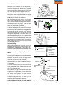
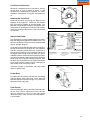
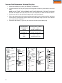
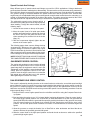
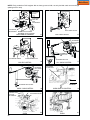
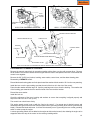
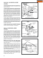
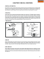
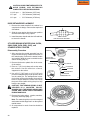
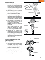
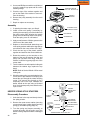
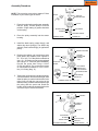
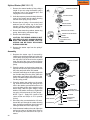
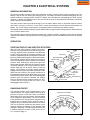
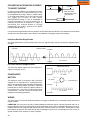
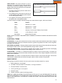
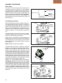
Main Menu ASSEMBLY PROCEDURE Welch Plugs To install a new welch plug after cleaning the carburetor, secure the carburetor in a vise equipped with protective jaws. Place the welch plug into the receptacle with the raised portion up. With a punch equal to the size of the plug hole, merely flatten the plug. Do not dent or drive the center of the plug below the top surface of the carburetor. After installation of the welch plug, seal the outer diameter with fingernail polish (diag. 41). Throttle Shaft and Plate When reassembling Tecumseh or Walbro carburetors, it is important that the lines, lettering, or numbers on the throttle plate are facing out when in the closed position. If the throttle plate has only one line, this line should be positioned in the 3 oclock position on Series 3, 4, and 7 carburetors, and at the 12 o'clock position on Series 1, 6, 8, 9 carburetors. (diag. 42 & 43). FLAT END PUNCH NEW WELCH PLUG SAME OR LARGER DIAMETER OF PLUG HOLE 41 THROTTLE PLATE THROTTLE LEVER TWELVE O'CLOCK POSITION 42 Test the operation of the throttle and return spring if equipped. If binding occurs, correct by loosening the screws and repositioning throttle plate. THREE O'CLOCK POSITION Always use a new screw(s) when reinstalling the throttle shutter to prevent the screws from loosening and being drawn into the engine. New Tecumseh screws are treated with dry-type adhesive to secure them in place. 43 NOTE: NEVER REUSE OLD SCREWS. On Walbro LMK and Series 7 carburetors, install the throttle return spring on the throttle shaft with the squared end up. Slide the foam dust seal over the spring. Insert the throttle lever assembly into the carburetor body with both tangs of the return spring on the left side of the center boss (viewed from throttle end) and the flat side of the shaft toward the carburetor mounting flange. Install the throttle shutter to the throttle shaft using notes or marks to place the shutter as originally found (Series 7 must have the line on the shutter at the 3 o'clock position) (diag. 44). Always use new throttle shutter screws when reinstalling. Install the screws so they are slightly loose. Apply light downward pressure on the throttle shaft and rotate it clockwise to seat the throttle shutter in the bore, then tighten the throttle shutter screws. Check for binding by rotating the throttle shaft. If necessary, adjust the throttle shutter by loosening and repositioning the shutter, then retighten the screws (diag. 45). DUST SEALS SERIES 7 THROTTLE LEVER THROTTLE PLATE WALBRO LMK SERIES 18 44 45 Main Menu Choke Shaft and Plate The choke plate is inserted into the air horn of the carburetor in such a position that the flat surface (if applicable) of the choke is down. Choke plates will operate in either direction. Make sure it is assembled properly for the engine. Test the operation of the choke and return spring function if equipped (diag. 46). CHOKE PLATE Always use a new screw(s) when reinstalling the choke shutter as the screws are treated with dry-type adhesive to secure them in place. The choke shaft and plate must be in the closed position prior to tightening the screws. Hard starting may be due to insufficient choking action because of a misaligned choke plate. Correct by readjusting the choke plate to close completely. Note the cutout position of choke shutter if applicable. On Walbro LMK and Series 7 carburetors, install the choke return spring on the choke shaft with the squared end up and hooked into the notch in the plate. Work the dust shield up around the spring and insert the choke shaft into the carburetor body. Rotate the shaft counterclockwise until the tang on the spring rests against the left side of the center boss on the carburetor body (viewed from choke end) . Rotate the choke shaft approximately 1/4 turn counterclockwise and insert the choke shutter into the slot in the choke shaft. Make sure the tabs on the shutter lock the choke shaft between them. Rotate the shaft and check for binding, the choke must return to the open position when released (diag. 47). 46 FLAT DOWN NOTE: NEVER REUSE OLD SCREWS. SPRING HOOKUPS Þ 47 PRESS IN PARTIALLY THEN APPLY LOCTITE SOME INLET FITTINGS STRAINER Fuel Inlet Fitting When installing the fitting, insert the tip into the carburetor body. Support the carburetor body with a wood block to avoid damage to other parts. Use a bench vise or press to install the fitting squarely. Press it in until it bottoms out (diag. 48). 48 RETAINER NUT Some carburetors may have a fixed main mixture or both a fixed idle mixture and main mixture, and are not adjustable. On Series 7carburetors, place the main nozzle spring into the main nozzle cavity. Apply oil to the main nozzle "O" ring and push the main nozzle into the cavity with the "O" ring end in first. Next install the "O" ring in the main jet cavity. Place the spring over the shoulder on the main jet and push the jet into the cavity with the main jet toward the "O" ring. Place a new gasket on the drain screw and tighten in position (diag. 50). On Walbro LMK carburetors, the main jet can be replaced by pressing it into the center leg of the carburetor until flush. (diag. 31 page 15). NOTE: FOR HIGH ALTITUDE JETTING, CONSULT BULLETIN 110. BRASS WASHER SPRING High and Low Speed Adjusting Screw, Main Nozzle When reassembling, position the coil spring on the adjusting screws, followed by the small brass washer and the O ring seal. Turn the high speed adjustment screw into the bowl nut and the low speed mixture screw into the carburetor body (diag. 49). "O" RING HIGH SPEED ADJUSTMENT SCREW 49 FLOAT HINGE PIN NEEDLE & SEAT SEAT RETAINING RING FLOAT MAIN NOZZLE EMULSION "O" RING POSITIONED IN GROOVE SPRING IDLE RESTRICTION BOWL "O" RING MAIN JET MAIN JET SPRING GASKET BOWL DRAIN BOWL RETAINER 50 19 Main Menu Inlet Needle and Seat Make sure the seat cavity is clean. Moisten the seat with oil and insert the seat with the grooved side down and away from the inlet needle. Press the seat into the cavity using a 5/32" (3.969 mm) flat punch, making sure it is firmly seated (diag. 51). On Series "7" carburetors, install the seat retainer into the cavity and push it down using the flat punch until it contacts the seat. PUSH IN UNTIL SEAT RESTS ON BODY SHOULDER 5/32" (3.969 mm) FLAT PUNCH IF YOUR CARBURETOR HAS A STEEL SEAT RETAINING RING RE-INTSALL AFTER SEAT INSTALLATION SEAT INSERT THIS FACE FIRST INLET NEEDLE SEATS AT THIS POINT The inlet needle hooks onto the float tab by means of a spring clip. To prevent binding, the long, straight end of the clip should face the choke or air filter end of the carburetor as shown (diag. 52). 51 CLIP OPEN END OF CLIP LONG END OF CLIP Points toward choke end THROTTLE END CHOKE END 52 Float Installation On Series 7 carburetors, slide the hinge pin into the hinge on the float. Position the needle into the fuel inlet and snap the float pin into the tabs on the float bowl. Float height is not adjustable. On Series 7 carburetors and the Walbro LMK, reinstall the inlet needle on to the float and place it into the carburetor (diag. 53). SERIES 7 WALBRO / LMK 53 1. When rebuilding a carburetor with a clip on the needle, position carburetor float side up for assembly. 2. Place the inlet needle and spring clip onto the float as shown. The long end of the spring clip must point towards the choke end of the carburetor. This will ensure that the inlet needle will move up and down in a straight line (diag. 53). 3. To set the proper float height on carburetors except Series 7 and Walbro LMK, see adjusting procedure. 4. Some Tecumseh float style carburetors have a damper spring which is installed as shown in diag. 55. CLIP OPEN END OF CLIP LONG END OF CLIP Points toward choke end 54 POINTS TOWARD THE CHOKE END 55 20 Main Menu Fuel Bowl And Bowl Nut Whenever a carburetor bowl is removed for service, the fuel bowl O ring (or gasket on Series "7") and the bowl nut washer must be replaced. For easier installation, lubricate the O ring with a small amount oil. DETENT Installing the Float Bowl Install the float bowl by placing the detent portion opposite of the hinge pin. Make sure the deepest end of the bowl is opposite of the inlet needle. The bowl has a small dimple located in the deepest part. The purpose of this dimple is to minimize the chances of the float sticking to the bottom of the bowl caused by stale fuel. 56 CARBURETOR FITTING Impulse Fuel Pump The diaphragms must be installed against the center body with the gaskets against the outside covers. The parts are designed so they cannot be misassembled without damage (diag. 57). To test the unit, assemble the carburetor to the engine, leaving the fuel line from the pump off. Use a different fuel tank remotely placed above the carburetor to provide gravity fuel flow to the carburetor inlet to run the engine while testing the pump. Make sure fuel is available in both fuel tanks and the original fuel tank's fuel line is connected to the fuel pump inlet. Place the pump outlet line in a proper draining receptacle. With the pulse line connected from the engine crankcase to the pump and the engine running, a definite fuel flow should result at the pump outlet. VALVE CLOSED ATMOSPHERIC VENT VALVE OPEN DIAPHRAGM FILTER AIR BLEED VALVE OPEN FUEL SUPPLY ê CRANKCASE PRESSURE PRESSURE ACTING á ATMOSPHERIC ON DAMPING DIAPHRAGM á FUEL FLOW SUCTION AND ê CRANKCASE FLOW DIRECTION á ATMOSPHERIC PRESSURE ACTING ON DAMPING DIAPHRAGM VALVE CLOSED PULSE LINE TO CRANKCASE FUEL FLOW DIRECTION á SUCTION ATMOSPHERIC PRESSURE ê CAUSED FUEL FLOW 57 If the flow is erratic or intermittent, the pump needs repair or replacement. Primer Bulb To install, start the retainer and bulb into the casting with the retainer tabs pointed out. Firmly push the bulb and retainer into position using a 3/4' (19.05 mm) deep well socket (diag. 58). Final Checks Before reinstalling a newly overhauled carburetor, preset the main mixture adjustment screw, the idle mixture adjustment screw and the idle speed adjustment screw. See Pre-sets and Adjustments in this chapter. 58 21 Main Menu CHAPTER 4 GOVERNORS AND LINKAGE GENERAL INFORMATION Tecumseh 4 cycle engines are equipped with mechanical type governors. The governor’s function is to maintain a R.P.M. setting when engine loads are added or taken away. Mechanical type governors are driven off the engine’s camshaft gear. The governor follower arm rests on the center of the governor spool on center force governors, and off to one side on other governor systems. Changes in engine R.P.M. cause the governor lever to move the solid link that is connected from the governor lever to the throttle in the carburetor. The throttle is opened when the engine R.P.M. drops and is closed as an engine load is removed. This chapter includes governor assembly linkage illustrations to aid in governor or speed control assembly. OPERATION As the speed of an engine increases, the governor weights on the governor gear move outward by centrifugal force. The shape of the governor weights force the governor spool to lift. The governor rod maintains contact with the governor spool due to the governor spring tension. The governor rod rotates causing the attached outer governor lever to push the solid link and close the throttle opening. When the engine speed decreases, the lower centrifugal force allows the governor weights to be pulled in by the governor spring. The governor rod rotates and the solid link moves the throttle to a more open position (diag. 1). SPRING THROTTLE GOVERNOR SHAFT WEIGHTS GOVERNOR SPOOL GOVERNOR GEAR 1 TROUBLESHOOTING Engine operation problems where the governor is suspected to be the cause may actually be the result of other engine system failures. Hunting (engine R.P.M. surging up and down) indicates that the engine is incapable of maintaining a constant R.P.M. with or without an engine load. Engine overspeeding must be corrected immediately before serious engine damage occurs. Use the applicable following procedure to diagnose a suspected governor failure. ENGINE OVERSPEEDING 1. If the engine runs wide open (faster than normal), shut the engine off or slow it down immediately. 2. Check the condition of the external governor shaft, linkage, governor spring, and speed control assembly for breakage or binding. Correct or replace binding or damaged parts. 3. Follow the governor adjustment procedure and reset the governor - see "Service" in this chapter. 4. Run the engine. Be ready to shut the engine off if an overspeed problem still exists. If the problem persists, the engine will require disassembly to inspect the governor gear assembly for damage, binding, or wear. 5. See Chapter 9 under "Disassembly Procedure" to disassemble the engine. 6. Remove the governor gear assembly. Repair or replace as necessary. ENGINE SURGING 1. Try to stabilize the engine R.P.M. by holding in one position the solid link between the governor arm and the carburetor throttle, using a pliers or fingers. 2. If the engine R.P.M. stabilizes, the governor or governor adjustment should be checked. See "Service" governor adjustment procedure in this chapter. If the engine R.P.M. does not stabilize, the engine will require additional checks see Chapter 9 under "Troubleshooting". 3. If the problem persists after the governor adjustment, check the engine R.P.M. found on microfiche card # 30. The R.P.M. settings are critical. If the R.P.M. setting for high and low speed are within specification and a slight surge is experienced, increasing the engine idle R.P.M. setting slightly may eliminate this condition. 4. Check the governor shaft or linkages for binding, wear, or improper hookup. Check the governor spring for adequate tension or damaged condition. Repair or replace as necessary. 22 Main Menu SERVICE GOVERNOR ADJUSTMENT With the engine stopped, loosen the screw holding the governor lever to the governor shaft clamp. Push the governor lever to move the carburetor throttle plate to the wide open position. Rotate the governor clamp counterclockwise on all overhead valve engines covered in this manual. Hold the lever and clamp in this position while tightening the screw (diag. 2). PUSH LEVER TO WIDE OPEN THROTTLE Ý GOVERNOR CLAMP SCREW Ú THROTTLE LINK GOVERNOR LEVER THROTTLE PLATE GOVERNOR ROD GOVERNOR SCREW GOVERNOR CLAMP SCREW 2 STANDARD LOCATION THROTTLE OPEN (PUSH COUNTERGOVERNOR CLOCKWISE) LEVER GOVERNOR ROD YOU MUST USE THIS LINK POSITION TURN CLIP COUNTERCLOCKWISE ON ALL VERTICAL SHAFT ENGINES EXCEPT VLV & VLXL. CLOCKWISE ON ALL HORIZONTAL SHAFT ENGINES EXCEPT OHH,OHSK 50,55 & OHM, OHSK 110,120. THROTTLE OPEN (PUSH COUNTERCLOCKWISE) ROTATE LEVER & ROD COUNTERCLOCKWISE OHH SERIES - NEW STYLE GOVERNOR CLAMP THROTTLE PLATE (TOP VIEW) ROTATE CLAMP COUNTERCLOCKWISE OHH SERIES - OLD STYLE 3 GOVERNOR GEAR AND SHAFT SERVICE After the cylinder cover is removed from the engine, the governor spool, gear, or governor shaft can be removed. On some governor assemblies, the retaining ring must be removed to allow the spool or gear to slide off the shaft. Other governor shafts use an upset to hold the governor spool on. If the gear requires replacement, the governor shaft will have to be removed. Governor Gear or Shaft Replacement, Upset Style Governor Shaft 1. Grip the original spool in a vise and use a twisting and pulling motion on the flange until the spool is free. 2. Clamp the shaft in a vise and pound gently on the flange with a wooden or plastic mallet to remove the shaft (diag. 4). NOTE: DO NOT TWIST THE SHAFT WHEN REMOVING. THE SHAFT BOSS MAY BECOME ENLARGED AND THE PRESS FIT WILL NOT SECURE THE NEW GOVERNOR SHAFT. 4 3. To install a new shaft, first assemble the gear and washer on the shaft. Start the shaft into the hole with a few taps from a soft faced hammer. 4. Place the flange in a press with a solid piece supporting the area below the shaft boss. Press the shaft in until a part # 670297 (.0125" / .3175 mm) shim just becomes snug (.010" - .020" / .254-.508 mm clearance) (diag. 5). GEAR SHIM WASHER SHAFT BOSS 5 670297 (modified) 23 Main Menu Governor Shaft Replacement, Retaining Ring Style 1. Remove the retaining ring, spool, gear assembly, and washer(s). 2. Clamp the shaft in a vise and pound gently on the flange with a wooden or plastic mallet to remove the shaft. NOTE: DO NOT TWIST THE GOVERNOR SHAFT WHEN REMOVING. THE SHAFT BOSS MAY BECOME ENLARGED AND THE PRESS FIT WILL NOT SECURE THE NEW GOVERNOR SHAFT. 3. Start the new shaft into the shaft boss by tapping with a soft faced hammer. 4. Refer to the chart at right for the proper shaft exposed length from the mounting surface. Add a drop of red Loctite 271 and press the governor shaft to the proper depth using a press or a vise. Wipe the extra Loctite off after installation. 5. Reassemble the washer (s), governor gear, and spool followed by the retaining ring. ENGINE MODEL OHH/OHSK50-70 OVRM OHM OHSK80-130 OVM OVXL OHV RETAINING RING SPOOL 1.350" - 1.365" (34.290-34.671 mm) 6 SERVICED AS ASSEMBLY RETAINING RING SPOOL SPOOL SPOOL UPSET WASHER SHAFT RETAINING RING RETAINING RING GEAR ASSY. (GOV.) WASHER EXPOSED SHAFT LENGTH 1.319" - 1.334" (33.502 - 33.883 mm) 1.085" - 1.100" (27.559 - 27.940 mm) GEAR ASSY. (GOV.) SPOOL GEAR ASSY. (GOV.) GEAR ASSY. (GOV.) SHAFT WASHER GEAR ASSY. (GOV.) SPACER WASHER WASHER SHAFT OVRM TYPE I 24 SHAFT 7 OVRM TYPE II 8 MEDIUM FRAME WASHER RETAINING RING WASHER SPACER NOTE; SPACER MAY BE PART OF THE GEAR ASSEMBLY. SHAFT 9 OHH / OHSK50-70 10 OVM / OHV / OHM OHSK80-130 11 Main Menu Speed Controls And Linkage Many different types of speed controls and linkage are used for O.E.M. applications. Linkage attachment points are best recorded or marked prior to disassembly. This assures the correct placement during reassembly. The solid link is always connected from the outermost hole in the governor lever to the throttle in the carburetor. The governor spring is connected between the speed control lever and the governor lever. Vertical shaft engines may use an adjustable intake pipe mounted speed control bracket located above the carburetor, or a vertical or horizontal control mounted on the side of the engine. The ignition ground out terminal, idle R.P.M. and high speed R.P.M. adjustment screws may be located on the speed control bracket. The adjustable speed control bracket which is mounted on the intake pipe must be aligned properly when installing. To align the control bracket, use the following steps. 1. Loosen the two screws on the top of the panel. 2. Move the control lever to full wide open throttle position and install a wire or aligning pin through the hole in the top of the panel, the hole in the choke actuating lever, and the hole in the choke (diag. 12). 3. With the components aligned, tighten the two screws on the control panel. The following pages show common linkage hookup arrangements. Whenever the carburetor or the governor linkage is removed or replaced, the engine R.P.M.'s should also be checked. Use microfiche card #30 or contact a local Tecumseh dealer for the correct R.P.M. settings for the engine model and specification. 12 HIGH SPEED STOP NOTE: RPM SETTINGS CAN ALSO BE FOUND ON THE COMPUTERIZED PARTS LOOK UP SYSTEMS. OHH REMOTE SPEED CONTROL The engine and equipment control must be adjusted to allow the engine control lever to touch the high speed stop when the equipment control is set in the "highspeed" or "fast" position. Loosen the bowden wire clamp, place the equipment control to the "fast" position, move the engine control lever to contact the high speed stop, and hold the lever in this position while tightening the bowden wire clamp. 13 OHH GOVERNED IDLE SPEED CONTROL This control is adjusted by bending the tabs on the control bracket to achieve the correct idle speed and high speed. When the engine is running, the governor controls both the idle and the high engine speed. In order for the governor to respond properly to a crankshaft load at engine idle, the idle speed screw on the top of the carburetor must be set 600 RPM lower than the governed idle speed. Use the following procedure to set the engine speeds (diag. 14 & 16). 1. Check to find the correct engine speeds found on microfiche card # 30 or using the Computer Parts Lookup System. 2. Start and allow the engine to run ( 3-5 minutes) before beginning adjustments. Place the control knob in the lowest engine speed position. Use a Vibra-Tach or other tachometer to set the non-governed idle speed (600 RPM lower than the governed idle speed) by pushing the bottom of the governor lever away from the control bracket so the throttle lever contacts the idle speed screw and hold the lever in this position. Turn the idle speed screw clockwise to increase or counterclockwise to decrease engine idle speed. 3. Allow the governor to control the throttle. Use a Vibra-Tach or other tachometer and bend the tab as shown to achieve the specified governed idle speed. 4. Slide the control knob to the high speed position and bend the tab as shown to achieve the specified governed high engine speed. 25 Main Menu NOTE: Early production OHH engines did not have governed idle, set only the idle crack screw and high speed governor stop. WINTER APPLICATION CONTROL GOVERNED IDLE LINK AND ADJUSTMENT HIGH SPEED ADJUSTMENT HIGH SPEED ADJUST BEND TO ADJUST SPEED DECREASE Þ INCREASE Þ OHH REMOTE & MANUAL 14 15 OHH FIXED SPEED THROTTLE CRACK SCREW T-10 GOVERNED HIGH SPEED ADJUST BEND Þ INCREASE GOVERNOR SPRING CORRECT BUSHING INSTALLATION DEEP SIDE HERE GOVERNED IDLE LINK 16 OHH RV CONTROL THROTTLE CRACK SCREW T-10 GOVERNED HIGH SPEED ADJUST Þ Þ Þ DECREASE GOVERNED IDLE TAB 17 OH / OHSK CONTROL LOW SPEED TAB HIGH SPEED PIN POSITION HIGH SPEED TAB Þ DECREASE Þ INCREASE GOVERNED IDLE SCREW OHSK / OHM CONTROL NOTE: ON REMOTE CONTROL THIS WILL NOT BE PRESENT OVRM SNAP IN CONTROL 19 OVRM 21 HIGH SPEED ADJUST LOW SPEED ADJUST OVRM 26 18 20 Main Menu HIGH SPEED ADJUST GOVERNED IDLE ADJUST OVM / OVXL GOVERNOR OVERRIDE 22 OHV11 - 17 SPEED CONTROL 23 SPEED CONTROL BRACKET DETENT BEARING PLATE CONDUIT CLIP BUSHING SCREW LOCK NUT CONTROL KNOB GROUNDING TERMINAL WAVE WASHER ADDITION BOWDEN WIRE BRACKET CONTROL LEVER WASHER NOTE: THIS CONTROL IS STANDARD ON SERVICE ENGINES AND IS OPTIONAL TO CUSTOMERS 24 CONVERSION TO REMOTE CONTROL Remove the manual control knob by squeezing together with a pliers or prying with a screw driver. Remove the air cleaner cover and air cleaner element to gain easier access to the speed control lock nut that holds the control levers together. Remove the 3/8" (9.525 mm) locknut, bushing, wave washer, control lever, and the detent bearing plate. Reassembly of REMOTE control. Discard the detent bearing plate and in its place install the washer with the smaller I.D. from the new parts bag. Install the lever over the post making sure that the end of the lever is in the slot of the control. Place the other washer with the large I.D. from the parts bag next to lever, then the bushing. The smaller side of the bushing goes towards the lever and fits inside of the lever and the washer. Discard the wave washer. Install the lock nut. Check the alignment of the lever, bushing and washers to ensure that everything is aligned properly and torque the lock nut to 20 in. lbs. (2 Nm). The control lever should move freely. This engine speed control is set up with the "stop in the control". If a remote stop is desired remove and discard the short green wire that runs from the speed control grounding terminal (to the remote grommet stop blade). Reinstall the blade and screw. It will now be necessary to run a grounding wire to a remote grounding switch in order to stop the engine. A remote grounding switch can be added to the engine at this terminal as well, thus allowing the engine to be stopped at either the stop in the control or the remote grounding switch. 27 Main Menu This remote speed control may have governed idle, a choke override, and the option of an ignition remote stop terminal block. The speed control is adjusted to the equipment throttle control by aligning the slot in the speed control lever with the alignment hole on the mounting bracket. Place a pin through the two holes, place the equipment throttle control to the wide open position, hook the bowden cable end in the control as shown, and tighten the cable housing clamp. In this position, the gap of .040" - .070" (1.02 - 1.778 mm) should exist at the gap location as illustrated. This will assure that the carburetor will go into full choke when the control is placed in the start position. The idle speed is adjusted by turning the idle speed screw clockwise to increase engine R.P.M. and counterclockwise to decrease R.P.M. Use tool part # 670326 to adjust the high speed engine R.P.M. Place the slotted end of the tool onto the adjustment tab and bend the tab to the left (away from the control) to increase engine R.P.M. Throttle plate alignment on all models with speed controls mounted on intake manifold. This adjusts choke in control as well (diag. 12 on page 25). OHV 11-17 HORIZONTAL SPEED CONTROL This speed control is adjusted to the equipment throttle control by aligning the slot in the speed control lever with the alignment hole on the mounting bracket. Place a pin through the two holes, place the equipment throttle control to the wide open position, hook the bowden cable end in the control as shown, and tighten the cable housing clamp. In this position, the gap of .040" - .070" (1.02 - 1.778 mm) should exist at the gap location as illustrated. This will assure that the carburetor will go into full choke when the control is placed in the start position. NOTE: Assure that the throttle cable has full travel from wide open throttle to full choke. Hard starting could result if the cable is not properly adjusted to allow for full choke. DECREASE INCREASE Þ OVM, OVXL, OHV VERTICAL SPEED CONTROL Þ HIGH SPEED ADJUSTING LEVER BEND TO ADJUST HIGH SPEED .040 - .070 (1.02 - 1.778 mm) GAP LOCATION CHOKE ADJUSTING TAB CONTROL LEVER HIGH SPEED PIN POSITION IDLE ADJUSTING SCREW OHV VERTICAL CONTROL 25 CHOKE HOOKUP HIGH SPEED ADJUSTMENT TAB THROTTLE LINK HOOKUP IDLE SPEED SCREW ALIGNMENT HOLE TOOL #670326 CHOKE LEVER AIR GAP (.040 - .070") (1.02 - 1.778 mm) BEND TAB TO ADJUST OHV 11 - 17 HORIZONTAL CONTROL 26 LINKAGE BUSHING The idle speed is adjusted by turning the idle speed screw clockwise to increase engine R.P.M. and counterclockwise to decrease R.P.M. Use tool part # 670326 to adjust the high speed engine R.P.M. Place the slotted end of the tool onto the adjustment tab and bend the tab to the left (toward the spark plug end) to increase engine R.P.M. OHV 11 -17 engines use nylon bushings on the throttle and choke linkage hook-up points to extend the life of the linkage and to enhance the stability of the governor system. Make sure they are in good condition and in place (diag. 27). 28 27 Main Menu CHAPTER 5 RECOIL STARTERS GENERAL INFORMATION Recoil starters used on vertical shaft Tecumseh engines are top mount horizontal pull style. Horizontal shaft engines use recoil starters which can be mounted to pull either vertically or horizontally. All recoil starters turn the engine over by engaging a dog(s) into the starter cup attached to the engine flywheel. All starters are spring loaded to retract the dog(s) when the engine speed exceeds the turning speed of the starter. OPERATION As the starter rope is pulled, the starter pulley rotates on the center pin. The starter dog(s) is pinned or pocketed in the pulley hub and extend outward when the pulley rotation forces the starter dog(s) to contact the ears on the retainer. The retainer ears act as a ramp to fully extend the starter dog(s). The fully extended starter dog(s) locks in contact with notches in the starter cup. When the engine fires and the rotational speed of the starter cup exceeds the starter pulley, the starter dog(s) disengages from the starter cup. The starter dog spring(s) returns the starter dog(s) to the disengaged position. When the starter handle is released, the recoil spring turns the starter pulley in the opposite direction to retract the starter rope. COMPONENTS ROPE HANDLE STARTER HOUSING HANDLE SPRING & KEEPER PULLEY AND REWIND SPRING ASSY. STARTER DOG HOUSING PULLEY DOG SPRING WASHER DOG SPRING RETAINER RETAINER BRAKE SPRING BRAKE SPRING WASHER SPRING PIN 1 DOG BRAKE WASHER CAM DOG CENTER 2 SCREW SERVICE Starter related problems will require the starter to be removed from the engine to diagnose the cause. Visually inspect the starter dog(s), starter cup, retainer, springs, rope, washers, and the starter pulley for wear or breakage. Use one of the following procedures that apply to the application to disassemble, repair, and assemble the starter. Always consult the Tecumseh Master Parts Manual for the correct replacement parts. ROPE SERVICE Rope replacement should be done using the correct part number replacement rope or braided rope of the correct diameter and length. Consult the Tecumseh Master Parts Manual to obtain the correct part number, length, and size required. Use the following rope chart to convert a numbered rope to a fractional diameter for bulk rope use. The rope ends should be cauterized by burning with a match and wiping the rope end with a cloth while hot. 29 Main Menu CAUTION: HANDLE MATCHES SAFELY TO AVOID BURNS, AND EXTINGUISH COMPLETELY BEFORE DISCARDING. # 4 1/2 rope = 9/64" diameter (3.572 mm) # 5 rope = 5/32" diameter (3.969 mm) # 6 rope = 3/16" diameter (4.762mm) ROPE RETAINER REPLACEMENT 1. Remove the starter handle if the retainer is a complete circle design. Remove the staple and old retainer. STAPLE 2. Slide the rope retainer into the proper position and insert the staple using a pliers. 3. Install the starter handle and tie a left hand knot to secure the handle. ONE PIECE ROPE RETAINER STYLIZED REWIND STARTER (OHH, OVRM, OHM, OHSK, OVM, OVXL, OHV), and STAMPED STEEL STARTER Disassembly Procedure 1. After removing the rewind assembly from the engine blower housing, release the tension on the rewind spring. Remove the starter handle and carefully allow the rope to unwind into the starter housing (diag. 4). 2. Remove the decal or plastic disc in the center of the rewind. ROPE HANDLE STARTER HOUSING PULLEY AND REWIND SPRING ASSY. STARTER DOG DOG SPRING WASHER 3. Place a 1" (25.4 mm) deep well socket under the retainer. Set the rewind on a bench, supported on the socket. 4. Use a 5/16" (7.937 mm) or a [1/4" (6.35 mm) punch for stamped steel] roll pin punch to drive out the center pin. The stamped steel center pin is driven out from the outside, the punch tip must be angled inside the center hole. Move the punch around while driving the pin to help keep the pin straight. 3 RETAINER LEFT-HAND KNOT BRAKE SPRING WASHER SPRING PIN 4 CAUTION: THIS REWIND SPRING IS NOT SECURED IN A CANISTER. PULLEY BOSSES HOLD THE REWIND SPRING AND COVER, AND CAN BE EASILY DISLODGED DURING HANDLING. 5. Remove the brake spring, retainer, washers, and pulley assembly (diag. 4). Note: The starter dogs face out on the stamped steel starter and the dogs face in on the stylized rewind starter. 6. All components in need of service should be replaced. 30 5 Main Menu Assembly Procedure 1. Reverse the disassembly procedure. The starter dogs with the dog springs must snap back to the center of the pulley (disengaged position). When the rope is pulled, the tabs on the retainer must be positioned so that they will force the starter dogs to engage the starter cup. (diag. 6 & 7) 2. Install a new recoil spring if necessary by pushing the new spring out of the holder into the pulley cavity while aligning the outside spring hook into the deep notch in the pulley. Push the spring cover in until seated. STARTER HOUSING HANDLE HANDLE INSERT ROPE PULLEY AND REWIND SPRING ASSY. NOTE: DO NOT DRIVE THE CENTER PIN IN TOO FAR. The retainer will bend and the starter dogs will not engage the starter cup. On the stamped steel starter the center pin should be driven in until it contacts the shoulder in the starter housing. 5. Replacing rope wind the starter pulley counterclockwise four or five turns to pre-load the recoil spring and thread the rope through the starter housing eyelet. Pull enough rope through to tie a temporary knot in the rope. Reattach the starter handle to the rope using a left-hand knot. Untie the temporary knot and allow the rope to recoil. WASHER STARTER DOG RETAINER BRAKE SPRING 3. Always replace the center spring pin with a new one upon reassembly. Place the two new plastic washers between the center leg of the starter and the retainer. New plastic washers are provided with a new center spring pin. Discard the old plastic washer. 4. Place the rewind on a flat surface and drive the new center pin in until it is within 1/8" (3.175 mm) of the top of the starter. DOG SPRING WASHER SPRING PIN 6 STARTER HOUSING HANDLE ROPE PULLEY AND REWIND SPRING ASSY. DOG SPRING STARTER DOG WASHER RETAINER LEFT-HAND KNOT BRAKE SPRING WASHER SPRING PIN 7 RETAINER WEDGE STYLIZED REWIND STARTER WITH PLASTIC RETAINER Disassembly Procedure 1. After removing the rewind assembly from the engine blower housing, remove the starter handle by first pulling a length of rope out using the handle, tying a temporary knot in the exposed rope, and either untying the knot in handle or prying out the staple. 2. Untie the temporary knot and slowly allow the rope to fully retract into the starter housing and the recoil spring to fully unwind. 3. Remove the decal from the center of the starter housing. STARTER HOUSING STARTER PULLEY SPRING & COVER DOG SPRING STARTER DOG DOG RETAINER 8 31 Main Menu 4. Use a small Phillips screwdriver or similar tool to pry the retainer legs apart and lift out the retaining wedge. RETAINING WEDGE (STEEL CLIP - NEW STYLE) 5. Pinch the legs of the retainer together and pull on the head of the retainer to remove it from the housing. STARTER HOUSING 6. Remove the pulley assembly from the recoil housing. 7. Repair or replace as necessary. Assembly STARTER PULLEY SPRING & COVER 1. If replacing the starter rope, see Step 8. 2. Install a new recoil spring if necessary by pushing the new spring out of the holder into the pulley cavity while aligning the outside spring hook into the deep notch in the pulley. Push the spring cover in until seated. DOG SPRING STARTER DOG 3. Apply a small amount of lithium grease to the inner bore of the center shaft. DOG RETAINER 9 4. Replace or check that both starter dogs are in the pulley pockets and that the dog springs are hooked on the outer surface of the dog. 5. Pinch the two legs of the plastic retainer together and start into the center shaft hole. 6. Rotate the retainer so the two tabs on the bottom of the part fit between the dog and pulley hub (left side of the dog). Push the retainer in until the leg prongs pop out of the center shaft. 7. Turn the starter over and snap the locking tab between the retainer legs, replace the top decal. NOTE: Refer to Service Bulletin 122 for metal locking tab. 8. Wind the starter pulley counterclockwise four or five turns to pre-load the recoil spring and thread the rope through the starter housing eyelet. Pull enough rope through to tie a temporary knot in the rope. Reattach the starter handle to the rope using a left-hand knot. Untie the temporary knot and allow the rope to recoil. STARTER HOUSING REWIND SPRING AND KEEPER ASSY. HANDLE KEEPER SPRING STYLE STARTERS Disassembly Procedure 1. Untie the knot in the rope and slowly release the spring tension. 2. Remove the center screw, retainer (cam dog on snow proof type), starter dog(s) and dog spring(s), and brake spring (diag. 10). 3. Turn the spring and keeper assembly to remove the pulley. Lift the pulley out of the starter housing. Replace all worn or damaged parts. 32 HANDLE INSERT ROPE PULLEY LEFT-HAND KNOT CAM DOG WASHER DOG SPRING STARTER DOG DOG RETAINER RETAINER SCREW BRAKE SPRING SPRING PIN "STAMPED STEEL WITH ROLL PIN" 10 Main Menu Assembly Procedure HOUSING NOTE: This procedure covers three starters. Follow illustration of your starter type as shown. 1. Place the rewind spring and keeper assembly into the pulley. Turn the pulley to lock into position. A light coating of grease should be on the spring. HANDLE SPRING & KEEPER ASSY. PULLEY BRAKE SPRING RETAINER DOG SPRNG RETAINER SCREW 2. Place the pulley assembly into the starter housing. "STAMPED STEEL" CENTER PIN 11 3. Install the brake spring, starter dog(s), and starter dog return spring(s). The starter dog spring(s) must hold the dog(s) in against the pulley. STARTER HOUSING 4. Replace the retainer cup (cam dog on snow proof starter) and retainer screw. Tighten to 65 - 75 in. lbs. (7-8.5 Nm) Older models that use a 10 - 32 retainer screw can be replaced with a larger 12 - 28 screw (part # 590409A). Re-drill the screw hole using a 13/64" (5.159 mm) drill bit. The center screw torque on cast aluminum starters is 115 to 135 in. lbs. (13-15 Nm) (diag. 11). ROPE HANDLE INSERT PULLEY LEFT-HAND KNOT 5. Tension the recoil spring by winding the pulley counterclockwise until it becomes tight, then allow the pulley to unwind until the hole in the pulley lines up with the rope eyelet in the starter housing. Install a knotted rope through the pulley and the eyelet and install the handle. A left-hand knot should be tied on the end of the rope to secure the handle. REWIND SPRING AND KEEPER ASSY. HANDLE CAM DOG WASHER DOG SPRING STARTER DOG DOG RETAINER RETAINER SCREW BRAKE SPRING SPRING PIN "STAMPED STEEL WITH ROLL PIN" HANDLE 12 HOUSING SPRING & KEEPER PULLEY DOG SPRING RETAINER BRAKE SPRING "ALUMINUM HOUSING" DOG BRAKE WASHER CAM DOG CENTER SCREW 13 33 Main Menu Stylized Starter (OHV 13.5 -17) 1. Remove the starter handle by first pulling a length of rope out using the handle, tying a temporary knot in the exposed rope, and untying the knot in the handle. STARTER HOUSING REWIND SPRING 2. Untie the temporary knot and slowly allow the rope to fully retract into the starter housing and the recoil spring to fully unwind. PULLEY 3. Remove the nut (using a 10 mm socket) and washers from the center leg of the recoil housing. Slowly unwind the dog spring by allowing the starter dog retainer to rotate. 4. Remove the starter dog retainer, starter dog spring, brake spring, and starter dogs. BRAKE SPRING STARTER DOGS STARTER DOG SPRING LEFT-HAND KNOT 5. Remove the starter pulley. STARTER DOG RETAINER WASHER CAUTION: THE REWIND SPRING IS NOT SECURED IN PLACE. HOUSING BOSSES HOLD THE REWIND SPRING, AND THE SPRING CAN BE EASILY DISLODGED DURING HANDLING. LOCKWASHER 6mm METRIC NUT 14 TYPE I 6. Remove the starter rope from the pulley if necessary. Assembly 1. Replace the starter rope if removed by inserting one end through the hole in the side of the pulley and tying a left hand knot near the rope end. Pull the knot into the squared area and wind the rope counterclockwise (viewed from the pulley bottom) on the starter pulley. STARTER HOUSING 2. Place the pulley on the housing center leg, align the end of recoil spring and the notch in the pulley and push down until seated. 3. Insert the starter dogs on the pulley pegs with the flat side away from the pulley, place the brake spring and starter dog spring on the pulley. The starter dogs must be free to retract into the pulley pocket. SPRING AND KEEPER 4. Place the starter dog retainer on the center leg, hook the end of the dog spring into the hole in the retainer, press down and turn 1/2 a turn clockwise to line up the notches to the starter dogs, add the nylon washer, metal washer, lock washer, and hex nut. Tighten the hex nut to 40 inch pounds (4.5 Nm) torque. NOTE: Type II - Apply blue Loctite to the center screw and torque to 70 in pounds (8 Nm). 5. Wind the pulley counterclockwise 4-5 turns, thread the rope through the starter housing hole, and place a temporary knot in the rope leaving at least one foot of rope length. 6. Slide the starter handle on the end of the rope and secure using a left hand knot. Remove the temporary knot and allow the rope to retract. 34 PULLEY STARTER DOG RETAINER SPRING WASHER STARTER DOG STARTER DOG RETAINER BRAKE SPRING CENTER SCREW LOCKWASHER TYPE II 15 Main Menu CHAPTER 6 ELECTRICAL SYSTEMS GENERAL INFORMATION The electrical system consists of three main elements: a battery, a starting circuit, and a charging circuit. The battery is part of both the starting and charging circuit. The battery should be checked before going into any extensive starter or charging system checks. If a battery has a shorted cell, overcharging can result, and the regulator or rectifier may appear to be at fault. If a cell has an open or high resistance connection, the electric starter operation will be affected. The power source used to provide the energy to turn an electric starter motor on Tecumseh engines is either 120 volt A.C. current or 12 volt D.C. A 120 volt A.C. starter circuit utilizes a 120 volt power source instead of a battery. The 12 volt battery models require a charging system to maintain proper battery charge. The starting circuit includes the battery, battery cables, starter or ignition switch, safety switches, starter solenoid, and an electric starter motor. The charging system consists of alternator charge coils, rectifiers or diodes, regulator, ignition switch, flywheel magnets, and a battery. All engines that have a charging system will use a combination of some or all of these features. OPERATION STARTING CIRCUIT AND ELECTRIC STARTERS After all of the safety interlock switches have been activated, the starter switch closes the starting circuit. A strong magnetic force is produced by the electrical current running through the armature windings. The armature magnetism repels the magnetism produced by the permanent field magnets of the electric starter. The repelling magnetic forces cause the armature to rotate, moving the drive pinion laterally on the splined armature shaft, meshing the starter pinion gear with the flywheel ring gear. When the drive pinion contacts the stop at the end of the armature shaft, the pinion rotates along with the armature shaft to crank the engine. The armature and pinion remain positively engaged until the engine fires and the flywheel rotates faster than the armature. The greater momentum of the flywheel throws the starter pinion gear out of mesh and forces the starter pinion back to the disengaged position. After the switch is released, the starting circuit is opened and the armature coasts to a stop. A small anti-drift spring holds the pinion in the disengaged position (diag. 1). LOCK NUT BOLT END CAP BRUSHES WASHER BRUSH SPRINGS NUTS BRUSH CARD HOUSING ARMATURE THRUST WASHER SPRING RETAINER END CAP RETAINER GEAR SPRING DUST COVER ENGAGING NUT 1 CHARGING CIRCUIT The charging system works independently of any manual controls. The engine needs to be running to produce an electric current flow. When a conductor (alternating coils) cuts the magnetic field generated by the magnets in the flywheel, a current is induced in the alternator coil. The permanent magnets in the flywheel have a magnetic field in which the lines of magnetic force run from the North Pole to the South Pole. As the flywheel rotates and the position of the magnets change, the direction of the magnetic field changes or alternates. The alternating coils are wound in different directions to allow current to flow as an A.C. waveform (diag. 2). ROTATION OF FLYWHEEL 2 35 Main Menu CONVERTING ALTERNATING CURRENT TO DIRECT CURRENT CATHODE ANODE In order to charge a battery, it is necessary to convert alternating current (A.C.) to direct current (D.C.). This is accomplished by using a diode or rectifier (diag. 3). A single diode makes use of only one half of the A.C. signal and is known as HALF WAVE RECTIFICATION (diag. 4). This is acceptable in certain applications. In certain situations it is necessary to make use of the entire A.C. signal. To accomplish this, multiple diodes in a bridge configuration are used to produce FULL WAVE RECTIFICATION (diag. 5). BAND OR OTHER MARKING INDICATES CATHODE END 3 Current flows through a diode when the anode is more positive than the cathode. The cathode end of the diode should point toward the battery when diode is used between a charging system and a battery. Half Wave Rectifier Single Diode The single diode allows only the positive half of the A.C. signal through. It does not allow the negative portion through. HALF WAVE RECTIFIER (SINGLE DIODE) + VOLTAGE + VOLTAGE A.C. INPUT - VOLTAGE D.C. OUTPUT 4 - VOLTAGE Full Wave Rectifier Bridge Rectifier FULL WAVE RECTIFIER (BRIDGE RECTIFIER) The full wave rectifier makes use of the entire A.C. signal, converting it to D.C. + VOLTAGE COMPONENTS - VOLTAGE A.C. INPUT BATTERY The batteries used in conjunction with Tecumseh engines are 12 volt lead acid or maintenance free style. The chemical energy produced by the dissimilar metals of the battery plates provides a electrical potential that is used to power the electric starter or unit accessories. Consult the original equipment manufacturers service manual for battery size, capacities, and testing procedure. A.C. INPUT + VOLTAGE (D.C.) + VOLTAGE D.C. OUTPUT - VOLTAGE 5 WIRING The wires used in Tecumseh electrical systems are copper stranded with an insulated coating around the copper strands. CONDITION: All wiring must be fully insulated between connection points, securely fastened and free of foreign material (such as rust and corrosion) at the connection points. This is especially important in the use of batteries where much of the potential may be lost due to loose connections or corrosion. Remember to check the insulation on the wire. All it takes is a pin hole for leakage to "ground out" on the engine or frame. This is of special concern when moisture or water is present. 36 Main Menu WIRE GAUGE: The proper thickness of wire is necessary in all electrical circuits. Wire diameter is measured in increments of gauge numbers. As the gauge number of the wire increases, the wire diameter decreases in size (diag. 6). THE LARGER THE NUMBER THE SMALLER THE WIRE # 18 1. The starter circuit wiring must be rated at #6 or lower gauge number. 2. The charging circuit wiring must be rated at #16 or lower gauge number (20 amp system requires #14 or lower gauge number). #6 6 3. The magneto circuit wiring (ground circuit) must be rated at #18 or lower gauge number. Tecumseh Products Company's standard wiring color codes effective August, 1992 are as follows: Code Product Yellow - Alternator A.C. Leads Red - Alternator D.C. + Leads Brown - Alternator D.C. - Leads Black - Alternator Ground Leads, Battery Ground Leads Orange - 12 Volt Starter B + Leads Dark Green - Ignition Shut-Off Leads NOTE: PRIOR TO AUGUST 1992, WIRE CODES CHANGED ACCORDING TO MODEL AND SPECIFICATION NUMBERS. ELECTRICAL TERMS ALTERNATOR - An alternator consists of coils of wire wound around a metal lamination stack. When a magnet is moved past the coils, a current is induced in the coils. In general, the greater the number of coils, the greater the output of the alternator. RECTIFIERS and DIODES - Charging a battery requires that the alternating current produced by the alternator be changed to direct current. This is accomplished by using a diode or rectifier. REGULATOR/RECTIFIERS - This combines a regulator with a rectifier. The regulator prevents overcharging of the battery and the rectifier changes the alternating current to direct current. CONDUCTORS - A conductor is a material that allows an electric current to pass through it. All metals are conductors of electricity, but some are better conductors than others. Silver, copper and gold are some of the better known conductors. INSULATORS - An insulator is a material that will not allow an electric current to pass through it. Some of the more common materials that are insulators are glass, plastic, rubber, ceramics and porcelain. BASIC CHECKS Before going into extensive checks, be sure to perform the more basic checks first, such as: 1. Battery defective or not charged. 2. Corroded or loose terminals or connections, or wrong connections. 3. Cracked insulation or broken wires. 4. A wire "grounding out" in the system. 5. Defective switch. 6. Operator presence system functioning properly.* *NOTE: ALL LAWN AND GARDEN TRACTORS BUILT AFTER JULY OF 1987 ARE REQUIRED TO HAVE AN OPERATOR PRESENCE SYSTEM AND MANY CAME EQUIPPED WITH SUCH A SYSTEM PRIOR TO THIS DATE. IF THE TRACTOR IS "CUTTING OUT" OR WILL NOT START, THIS IS AN AREA THAT SHOULD BE CHECKED OUT. 37