1
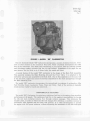
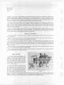
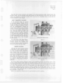
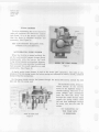
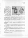
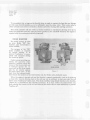
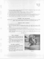
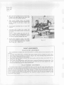
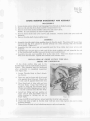
Bulletin 9D-7
August, 1951
Second P~inting
Model "BB"
Page I
Model "BB" Carburetor
SERVICE MANUAL
UNITED MOTORS SERVICE -AC DIVISION
General Motors Products of Canada, Limited
OSHAWA
-
ONTARIO
Bullerin 9D-7
Aueusr. 1951
~ o d e "l B B
Page 2
COPYRIGHT 1951
Bulletin 9D-7
Auausr. 1951
Model "BB"
Page 3
7
.
r
FIGURE 1. MODEL " B B CARBURETOR
The new Rochester Model "BB" Carburetor incorporates a number of distinct features. Foremost of these features is the concentric float bowl, which completely encompasses the main
bore of the carburetor. This float bowl concentricity in conjunction with the centrally located
main discharge nozzles, prevents fuel loss on road inclines. Regardless of the angle the car
may assume, the fuel level is a t all times below the nozzle spill point.
A second feature of the model "BB" carburetor is the design of t h e Main Well Assembly.
This assembly contains the Main Metering Jets and the Power Valve. It is attached t o the
carburetor air horn and suspended in the float bowl. Due t o t h i s suspension of the main well
in the fuel bowl, engine heat cannot be directly transmitted to the main passageways through
the Main Metering Jets.
The model "BB" carburetor incorporates the conventional six systems of carburetion; Idle,
P a r t Throttle, Power, Accelerator Pump, Float, and Choke. Each of the systems is basically
simple and can readily be traced and understood.
PERFORMANCE FEATURES
F
The model "BB" Carburetor, by metering a continuous fuel flow to the engine, gives smoother
performance a t all speeds. The continuous fuel flow to the engine is accomplished by having
the idle and main metering systems flow through common passages. This eliminates t h e
transfer point, or point a t which the idle fuel changes flow direction, a condition common t o
carburetors with separate idle and main well systems. It is often advantageous t o operate
the engine with full power mixtures without advancing the accelerator to the full wide-open
Bulletin 9D-7
August, 1951
Model "BB"
Page 4
position. By the use of the vacuum operated power system in the new carburetor, these power
mixtures a r e readily available. This is due to the ability of the power valve to function a t any
drop in manifold vacuum below approximately 7" Hg., regardless of the degree of throttle opening. In carburetors which employ a mechanically operated power system, the throttle must be
advanced to almost full wide open position to obtain the power mixtures.
For good initial acceleration and to minimize hard starting in hot weather, the model "BB"
unit employs a vented type of pump plunger. U7hen the engine is not operating, the rise in
heat from the engine manifold causes the fuel in the pump system to boil. The increased
pressure from this boiling in conventional units often times forces the fuel from the pump
system into the engine.
The new type carburetor has a ball type check valve built into the plunger head. As a consequence, any fuel boiling below t h e pump plunger, is automatically vented by t h e ball check
into the float bowl. This system always provides solid fuel in the pump chamber for smooth
acceleration under relatively high temperature operation.
SERVICE FEATURES
The Model "BB" Carburetor has been designed with simplicity of construction and maximum
ease of service.
Both the idle tubes and pump jets, being pressed into the air horn and bowl castings respectively a t the factory, need never be replaced or serviced.
In many instances the entire unit will not have to be removed from the engine. All of the
main metering parts a r e in the air horn assembly. By simply removing the cover screws and
disconnecting the heat tuhe, choke arm, and pump rod, i t is posable to service 0;' inspect the
floats, float valve assembly, main well support assembly, power valve assembly, and automatic
choke assembly.
With t h e exception of t h e initial idle adjustment t h e model "BE" carburetor does not require
any part throttle or power mixture adjustments.
Since carburetion is dependent upon both compression and ignition, the carburetor should
always be adjusted last in engine tune-up.
..
IDLE SYSTEM
At small throttle openings, the
vacuum created a t t h e main discharge
nozzles is not great enough to cause
fuel t o flow out of the nozzles. Therefore, a n additional system has been
introduced to provide the relatively
rich mixture ratios 'equired throughout t h e idling range.
As shown in Figure 2, the idle fuel
.--.
,
,
first passes from the bowl through
the calibrated main metering jets in
.-" <*"em
the bottom of the main well suvvort
assembly. The fuel is then drawn up
is" IDLE SYSE
the main well bv manifold vacuum to
-.
E l om,r*
--t h e Air Horn crossbar.. Air is bled
into t h e solid fuel a t the calibrated air bleeds above the nozzles. This fuel/air mixture then
passes through the calibrated idle tuhe, (additional air entering thru t h e crossbar idle air
bleeds) and passes down the passage in the Float Bowl to the Throttle Body.
.
8 LE
8
"
Bullerin 9D-7
Aupcisc. 1951
h l o d r l "BB"
.-
Page
5
The idle fuel is then metered to the engine by the idle adjusting needles located below the
throttle valves. As the throttle valves are opened, the idle discharge holes above the throttle
valves a r e exposed to manifold vacuum, thus becorziing fuel discharge holes to meet the increased demand of the engine
PART THROTTLE SYSTEM
As the throttle valves are opened
to a greater degree, (Figure 3) the
suction created a t the main discharge
nozzles by means of manifold vacuum
and the multiplication created by
means of t h e primary and secondary
venturi, becomes great enough to pull
fuel from the nozzles, through the
main metering jets, the main -well
channels and t h e crossbar channels.
At this point air is bled into this fuel
through the crossbar bleeds. The fuel
is thus discharged from the main discharge nozzles rather than through
the idle system.
The calibration of the Main Metering Jets and the Air Bleeds in the
crossbar control and maintain the
economical fuel/air ratios throughout
this part throttle driving range.
MODEL"B5 PART THROTTLE SYSTEM
Figure 3
POWER SYSTEM
Although the part throttle system
is calibrated to give maximum economy under normal driving conditions,
some means must be provided by
which increased fuel is supl~liedwhen
more power is desirable or sustained
high speed driving is t o be maintained. This is accomplished by means
of a vacuum operated power piston.
(See Figure 4. Note piston in "Down"
position).
MODEL "88' POWER SYSTEM
Figure 4
The power piston vacuum channel is open t o the manifold beneath the throttle valves. The
vacuum in this channel varies with the manifold vacuum. The power piston actuating spring
is so calibrated a s t o force the piston down when the manifold vacuum drops helow approximately 7" Hg. This situation occurs a t driving speeds over approximately 7 5 MPH. or on rapid
acceleration. When the power piston is down i t unseats the spring loaded power valve permitting a n additional fuel flow from the bowl through the power restrictions and into the main
well channels. This additional fuel is supplied a s long a s the manifold vacuum remains below
approximately 7 inches Hg.
There is no adjustment required for the part throttle or power systems.
Bulletin 9D.7
August, 1951
Model "BB"
Page 6
FLOAT SYSTEM
To aid in maintaining the correct fuel level
under all conditions the carburetor employs
twin floats. It is of the utmost importance
that the floats be adjusted carefully and
accurately. (See Figure 5)
SEE ADJUSTMENT BULLETIN FOR
CORRECT FLOAT SETTING.
ACCELERATING PUMP SYSTEM
When the throttle is opened suddenly the
a i r flow and manifold vacuum change almost
instanteously, while the heavier fuel tends
to lag behind causing a momentary leanness.
The accelerator pump provides the additional
fuel necessary for smooth operation on ravid
acceleration. (See Figure 6)
;
;
'
MODM " B B FLOAT SYSTEM
I
Figure 5
A double spring pump plunger is used on the model "BB" carburetor. The rates of compression of the top spring versus the bottom spring are calibrated to insure a smooth, sustained
charge of fuel for acceleration.
On the pump intake stroke, fuel passes through the pump inlet screen, unseats the inlet
ball, and fills t h e pump well.
The accelerator pump, being connected directly to the throttle,
,, " ~*
moves a t t h e slightest change in
mo, throttle opening. The force of the
pump plunger upon acceleration
seats the inlet ball, forces fuel
through the outlet channel which
unseats the spring loaded outlet
ball and then discharges through
the pump jets, into the main air
stream.
t,,"p
",
LE E.
I
mum1 -68" PUMP SYSAM
Figure 6
NO TARGETING OF
THE PUMP JETS
1s REQUIRED.
Bulletin 9D-7
August, 1951
lrlodel "BB"
Paae 7
CHOKE SYSTEM
The model "BB" carburetor
employs a fully automatic
choke^ to insure proper starting and driving during cold
weather operation. This choke
system is composed of a thermostatic coil, piston, choke
valve, and fast idle cam linkage. It is controlled by a combination of intake manifold
vacuum, the offset choke
valve, atmospheric temperaheat. (Figure 7)
When the engine is cold the
thermostatic coil is calibrated
to hold t h e choke valve closed.
--
#*lllll*-oil---'--i s . l i s l r ..."*"'"""II
r
x e
"s*'v'
# V * '
iI
:
t
L
,.
.
.*
;
MOOR "'$0" CHOKi SYS
Figure 7
As the engine is started, air velocity against the offset choke valve causes the valve to open
slightly against t h e torque of the thermostatic coil. In addition, intake manifold vacuum is
applied to the choke piston which also tends to pull the choke valve open. As a consequence
t h e choke valve assumes a position where t h e torque of t h e thermostatic coil is balanced
against vacuum pull upon the choke piston and air velocity against the offset choke valve,
thereby causing a regulated air flow into the carburetor which provides a richer mixture during
the warm-up period.
During warm-up, the Choke piston serves to modify the choking action to compensate for
varying engine loads or acceleration. Any acceleration or increased road load decreases the
vacuum exerted on the choke piston. This allows the thermostatic coil torque to momentarily
increase choke valve closure to provide the engine with a sufficiently richer mixture for
acceleration.
As the engine warms up, hot air from the exhaust manifold "stove" is drawn into the thermostatic coil housing. This hot air causes a rise in temperature which causes the coil t o slowly
relax its tension. Thus the choke valve is allowed to move gradually to the full open position
as the engine warms up.
To prevent stalling during the warm-up period, i t is necessary to run the engine a t a slightly
higher idle speed than for a warm engine. This is accomplished by the fast idle cam which is
linked to the choke valve shaft and holds the throttle valve open sufficiently during the warm-up
period t o give the increased idle RPM, until such time as the choke valve moves to the full
open position.
While the automatic choke is in operation, the driver may wish to advance the throttle to
the full wide open position. Since this would decrease vacuum pull upon the choke piston
thereby closing the choke valve, i t is necessary to provide increased carburetor air flow by
opening the choke valve mechanically.
Bullerin 90-7
August, 1951
Model '88''
Page 8
To accomplish this, a tang on the throttle lever is made to contact the fast idle cam linkage
a t wide upon throttle position so as to sufficiently open the choke valve. This is also called a
choke unloader and serves to dechoke a flooded carburetor during cold starting operation.
This choke unloader will also relieve a flooded condition on starting by allowing more air to
enter the carburetor and mix with the excess gasoline in the manifold whenever the engine is
cranked with the accelerator held fully depressed.
CHOKE MODIFIER
Thechokesystem.aSused
on some ~ o d e l"BB" Carburetors, also incorporates a
choke modifier.
-w-~m'"""":;;;:-r~""""
E l r r a . xP r- ,* ;X ;* * ~ ~ ~ * ~ " * " " , , , l
?'"'"''-*.~---',
,..*'
;,
The purpose of the "BB"
choke modifier, as required
by certain engines, is to
prevent "loading up" or excessively rich mixtures during
the warm-up period.
Under normal operating conditions, the automatic choke
assumes a position where the
torque of the thermostatic coil
is balanced against the vaCHOKE MOI
cuum pull on the choke piston
plus the air velocity against
Flgure 8
the offset choke valve. As the
heat from the exhaust manifold relaxes the tension on the thermostatic coil, the choke valve gradually opens.
8 ,
-
?,
When the engine is started cold and the throttle is opened considerably (such as in going up
a steep hill), vacuum drawing heat to the coil may not be sufficient to heat and relax the coil
before some "loading up" takes place. The choke modifier, being linked directly to the throttle,
(Figure 8) is actuated by this throttle movement. It in turn rotates the thermostatic coil,
thus relaxing the tension on the coil and allowing the choke valve to open sufficiently to prevent
"loading up".
Bulletin 9D-7
August. 1951
hlodel "BB"
Page 9
DISASSEMBLY OF MODEL "BB" CARBURETOR
CHOKE DISASSEMBLY
1. Loosen %'' brass fitting on choke suction tube
2. Remove three attaching choke cover screws and retainers, then remove choke cover,
Cover Gasket, and Thermostatic Coil assembly from choke housing,
3. Remove Baffle plate.
4. Remove cotter pins from each end of choke rod and remove rod.
5. Remove retaining screw a t end of choke shaft and carefully pry off choke trip lever, spacing washer, and choke counter weight.
6. Remove two choke valve screws and then remove choke valve.
7. Rotate choke shaft counter clockwise to free choke piston from housing and then remove
piston and choke shaft from carburetor.
8. Remove choke piston pin and piston from choke shaft.
9. Remove two choke housing attaching screws. Choke housing and gasket may now be
removed from Air Horn.
AIR HORN
1. Remove filter screen retainer nut and gasket with
3/4"
wrench and remove filter screen.
2. Remove clip on upper end of pump rod and cotter pin on bottom. Remove pump rod from
rocker arm.
3. Remove cotter pins from center and end of rocker arm and remove rocker arm and spacing
washer from Air Horn.
4. With carburetor upended on a flat surface, remove four Air Horn screws.
5 . With carburetor again in an upright position, remove remaining four Air Horn screws and
lift Air Horn gently from bowl. (If necessary, lightly tap sides of Air Horn to break the
gasket seal.)
6. Place Air Horn upended on a flat surface. Remove float hinge pin and lift float assembly
from Air Horn.
7. Press rubber seal on pump plunger arm through Air Horn and remove both the seal and the
pump plunger. Then separate pump plunger and the rubber seal.
8. Remove float needle seat and gasket with a %'' bit screwdriver.
9. Remove main metering jets from main well support.
NOTE: I t is not necessary to remove power valve assembly.
10. Loosen two screws and remove main well support. Air Horn gasket may now be removed.
11. Remove power piston and actuating spring.
12. Loosen screw and remove secondary venturii cluster.
13. Carfully remove float balance spring and clips.
14. Remove retaining clip and pump vent disc from Air Horn.
August.
hlodel
1951
"BB
Page 10
BOWL DISASSEMBLY
1. Remove pump return spring and intake ball from pump well.
NOTE: Hold pump outlet guide while removing inlet ball.
2. Carefully remove pump screen from bowl.
3. Invert the bowl and remove pump discharge spring guide, spring, and ball.
4. Upend carburetor bowl (be careful to let the heat tube hang over the end of the flat
surface) and remove four throttle body attaching screws. The throttle body and gasket
may now be removed.
THROTTLE BODY DISASSEMBLY
1. Remove idle adjusting needles and springs.
2. Remove idle and fast idle screws from throttle lever.
NOTE: Do not remove throttle valves from throttle body.
Due to the close tolerance fit of the throttle valve, and the fact that the idle discharge holes
are drilled in relation to the throttle valve in the closed position, the throttle body and
valve should be replaced as a complete assembly when wear is noted a t the throttle valve,
shaft, or throttle body bore.
3. Loosen screw and remove fast idle cam.
NOTE: I t is not necessary to remove choke suction tube from throttle body.
CLEANING OF PARTS
1. Thoroughly clean carburetor castings and metal parts in carburetor cleaning solvent.
CAUTION: Choke coil and housing and pump plunger should not be immersed in solvent.
Clean pump plunger in clean gasoline only.
2. Blow all passages in castings dry with compressed air and blow off all parts until they
are dry.
CAUTION: Do not pass drills or wires through calibrated jets or passages as this may
enlarge orifice and seriously affect carburetor calibration.
3. Clean filter screens for dirt or lint. If they are distorted or remain plugged, replace.
INSPECTION OF PARTS
1. Check floats for dents or wear a t hinge pin holes. Shake float to check for leaks. Replace
if necessary.
2. Examine float needle and seat. If grooved replace with a factory tested and matched float
needle, seat and gasket assembly.
3. Check choke shaft for wear in the bores. If worn excessively replace part.
4. If throttle shaft or valves appear loose due to wear, replace throttle body assembly.
5 . Inspect holes in pump and throttle levers. If worn out of round they should be replaced.
6. Inspect idle adjusting needles for burrs or ridges. Replace if necessary.
Bulletin 9 D - 7
August, 1951
,-
Model " B B
Page 11
7. If wear is noted on steps of fast idle cam, i t should be replaced a s it may upset engine
idle speed during t h e choking period.
8. Inspect pump plunger leather. Replace plunger if leather is damaged.
9. If gaskets appear hard or brittle, replace t o insure a proper seal.
10. Check to see t h a t lower end of choke suction tube is tight in seal in throttle body. If not, a
new seal will have to be installed after the carburetor has been completely assembled.
11. Inspect suction tube nut packing. If compressed or out of round, replace
ASSEMBLY AND ADJUSTMENT
IMPORTANT: To prevent poor economy due to fuel leakage all threaded parts must be installed
tightly. This applies especially to the strainer nut and float needle seat.
1.
2.
3.
4.
THROTTLE BODY ASSEMBLY
Install idle screw in throttle lever.
Screw Idle adjusting needles and springs into throttle body until they are finger tight.
Back out screw 1%turns a s a temporary idle adjustment. Make final adjustment on
engine.
Install fast idle cam and fast idle screw to throttle lever.
Upend bowl, place throttle body gasket in position and attach throttle body. Tighten screws
evenly and securely.
NOTE: New choke suction tube seal, if needed, will be installed after carburetor is completely assembled.
(See Page 15.)
BOWL ASSEMBLY
1. With bowl again in upright position, drop
small aluminum pump inlet ball into
pump well hole and replace pump return
spring.
2. Install large steel ball in pump discharge
cavity. Place spring and pump discharge
guide on top of ball. (Figure 9)
3. Press pump screen carefully into position.
AIR HORN ASSEMBLY
1. With Air Horn upended on a flat surface,
install float needle seat and gasket, using
screwdriver with a %" bit.
2. Place small pump vent disc and retaining
clip into pump vent.
3. Place Power Piston spring and Power
Piston into vacuuni cavity. Piston should
ride free in cavity.
Fiyre 9
Bulletin 9D.7
August, 1951
Model "BB"
Page 12
4. Place air horn gasket on top of air horn.
Check to be sure that all air horn and
gasket holes a r e properly aligned.
-
q;r - - : -
, a
. ..- .- ..*..-.
,
-""""-
-
+I
5 . Hold Power Piston down and attach
main well support over power piston and
attach screws to air horn evenly and
securely.
6. Install main metering jets in main well
support.
'7. Assemble clip t o float and needle and
assemble float needle in seat and float to
air horn.
NOTE: Float needle and seat are factory matched and if replacement is required, they should be replaced in pairs
as factory matched needle and seat.
)at Tan
--"m.
8. Install float balance spring and clips.
Place float carefully in position with tang
a t rear of float facing air horn. Install
float hinge pin. (Figure 10)
1
FLOAT ADJUSTMENTS
FLOAT LEVEL ADJUSTMENT
This adjustment is made with air horn gasket in position and air horn inverted on flat
surface.
1. Carefully bend float arms vertically until floats appear level in relation to each other.
2. Place Float Gauge in position as shown, (Figure 11) with locating tangs inserted into
the secondary venturi to position gauge.
3. Bend float button, which contacts the float needle, until the floats just touch the top
portion of t h e gauge
4. Now bend arms horizontally until each float is centered between the gauge legs. Tilt
Air Horn assembly 90° each side and check that floats do not touch gauge legs. This
insures the floats will not rub sides of float bowl.
FLOAT TENSION ADJUSTMENT
To insure proper fuel level and sufficient entry of fuel into the ljowl under high speed
operation the float tension adjustment must he made as follows: bend the float tang, a t
the rear of the float, against the balance spring to lessen the drop and away from the
balance spring to increase the drop. The tension is correct when the distance from the
bottom of the air horn gasket to the bottom of the floats, with the air horn assembly held
in an upright position, is equivalent to the distance marked between alrows on the
carburetor float gauge.
Augusr. 1951
Model " B B
Page 13
.
rt Gauge
-**.
Locotino Groove
?from Legs of Gouge
,"-*=*#,",
. - . a
d*..d.*-:-L?.+
1,,
-*a*-
Figure 11
Figure 12
Place rubber seal on pump plunger arm
and pull seal through air horn until i t
positions in its groove on casting.
Install venturi cluster in its groove in
air horn. Figure 12.
rVit11 bowl in upright position, place air
horn assembly on bowl so t h a t screw
holes line up. Guide pump plunger
against pump return spring and be careful not t o hit float on sides of bowl.
Install and tighten four air horn screws
evenly and securely.
Upend carburetor, install and tighten
remaining four air horn screws evenly
and securely.
Install filter screen, strainer nut and
gasket assembly in air horn.
Install pump rocker arm on to shaft.
Then install pump plunger arm to rocker
arm. (Figure 13.)
Figure 13
.:
Bullerin 9D-7
Model "BB"
Augusr,
1951
Page 14
16. Install washers and cotter pins.
17. Place choke housing gasket in position
and place choke housing on suction tube
and install choke honsing on air horn
hushing. Tighten screws evenly and
securely. NOTE: Be certain packing is
on suction tube.
18. Tighten choke suction tube nut to choke
honsing. Fitting must be tight to prevent loss of vacuum.
19. Assemble choke piston t o shaft with pin
and place into choke housing bore. Rotate
choke shaft clockwise so t h a t piston
rides in piston housing cavity.
20. Install choke valve on choke shaft. Center choke valve before tightening screws.
Letters R P must face outward.
21. Place baffle plate in position, and install
choke coil, cover, and gasket. Rotate
cover until index marks on cover and
housing a r e aligned. Attach three retainers and screws t o choke housing and
tighten securely.
Figure 14
Index Pointer
:
22. Place choke counter weight on end of
choke shaft. Letters R P must face outward. Install spacing washer and trip
lever so that tang of trip lever is on top
of counter weight tang, when choke valve
is full open.
23. Install choke rod, with offset end to
counterweight and other end t o the fast
idle cam. Assemble cotter pins t o each
end of rod. Turn ends over to prevent
binding or interference. (Figure 14.)
NOTE: Check choke valve for free
movement.
24. Install pump rod into rocker arm and
fasten with clip. Then install lower end
into throttle lever and fasten with cotter
pin.
Figure 1 5
Bulletin 9D-7
August, 1951
hlodel " B B
Paae 15
C H O K E MODIFIER DISASSEMBLY A N D ASSEMBLY
DISASSEMBLY
1. Loosen choke suction tube nut and disengage from threads on choke housing.
2. Remove rod end clips from choke modifier rod and remove rod.
3. Remove screw from choke modifier index lever and remove lever.
NOTE: It is not necessary to remove index pointer.
4. Remove three choke stat cover screws and retainers. Remove choke s t a t cover and coil
assembly.
5. Remove throttle shaft choke modifier lever.
1.
2.
3.
4.
ASSEMBLY
Assemble throttle shaft choke modifier lever to throttle shaft. The letters RP should face
outward and the lever should be pointed towards the choke housing with the throttle
valves closzd. (Figure 15.)
Assemble the stat cover and coil assembly and the three choke s t a t cover screws and
retainers.
Assemble the rod end clips to each end of the choke modifier rod and assemble the rod
to the throttle shaft modifier lever and the s t a t cover modifier lever.
Assemb!e the stat cover modifier lever to the stat cover. This lever should be directed
away from the fuel inlet. Tighten the modifier lever retainer screw.
INSTALLATION OF CHOKE SUCTION TUBE SEAL
MODEL "BB" CARBURETOR
. . . , ..
If the choke suction tube seal in the
,, . Tube Scirl-Punch
throttle body requires replacement proceed as
;'.
follows: This operation must be performed
::
after carburetor is completely assembled.
is
(See Figure 16.)
"".
.,id%
%
~
1. Loosen Throttle Body to Bowl Attaching Screws.
2. Place new seal on lower end of tuke and
slide against flared tube end. Flared side
of seal must fit against flared tube end.
3. Place flared end of tube with seal into
Thrott!e Body. Using Tool BT-45 tap
lightly to hold seal into Throttle Body.
Rotate tube while tapping seal so that it
is started uniformly into Throttle Eody.
4. Install hex fitting and new packing on
upper end of tube and fasten tube to
choke housing by turning hex nut up
finger tight.
.
<
Suction
.
..
,
Figure I 6
5. Using tool BT-45 and hammer spread seal into throttle hody securely.
6. Check that tube is tight in throttle hody (will not turn) then tighten hex nut to choke
housing securely.
7. Tighten throttle body to bowl attaching screws evenly and securely.