1
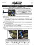
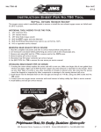
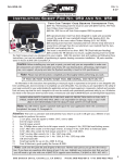
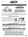
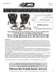
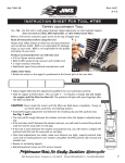
No.1042-IS
Rev H
10-12
A Division of Thiessen Products, Inc.
Instruction Sheet For Tool #939 & #958
Late Style Wheel
Sealed Bearing Puller
/ Installer
18
No.939
16
1
No.958
13
14
3
8
11
10
17
2
7
4
9
12
6
15
5
Use on all 2000-present Twin Cam®
models, and all 2000 Sportsters®
models, and V-Rod®s 2002-present.
Use on all 2007-present wheels
using 25mm wheel bearing, ABS or
non-ABS.
Note: Read entire instruction sheet before performing
work.
• Remove wheels and prep per H-D® service
manual.
• Refer to the exploded detail drawing for fitment of No.1042-1 and No.1042-2 and
No.1042-8 bearing puller.
• Refer to the exploded detail drawing for fitment of No.1042-4 and No.1042-5 and
No.1042-9 bearing installer.
Removal Notes:
1. On models with a hub plate, remove hub plate from disc wheel wheel on opposite side of front brake disc.
2. Some wheel hubs may not provide adequate support for the main body puller. In these cases, center a used brake
disc rotor over the the hub to support the main body puller.
A. Front Wheel Bearing Removal
1. Place the wheel vertically in a vice. (Protect the rim from being marred in the vice)
2. Assemble the remover tool. See parts list for the tool lubrication locations before using. Always replace both
bearings per hub.
A.
Install No.1042-1, 1042-2, or No. 1042-8 into bearing per bearing I.D.used. See parts list for the size
reference. When installing puller tool into bearing do by hand or use a rubber mallet to push through
bearing I.D. Stop pushing on bearing puller as soon as it has cleared the inside of bearing race. You
should hear a slight click.
Note: Do not damage the threaded end of tool with hard face hammer.
B.
Place bridge No.1042-3 over bearing puller 1042-1 depending on bearing size with the fingers of
bridge facing the wheel. Lightly oil all threads.
C.
Place the large brass washer No.1099 and large nut No.1098 onto the puller and hand tighten the nut
until it stops at the top face of bridge.
3. Removing Wheel Bearing
A.
Insert the bearing expander, No.1042-7 through the other side of wheel bearings, and thru the bear
ing puller. Apply a small amount of oil to the taper at the hex end of expander No.1042-7.
B.
Torque the expander nut, No.7515 to 100 in/lbs with a 11/16” wrench or socket at the same time
CAUTION: Wear safety glasses. Excessive force may damage parts!
See JIMS® catalog for Hundreds of top quality professional tools.
The last tools you will ever need to buy.
1
555 Dawson Drive, Camarillo, CA 93012 Phone 805-482-6913 • Fax 805-482-7422
No.1042-IS
Rev H
10-12
A Division of Thiessen Products, Inc.
Instruction Sheet For Tool #939 & #958
holding the other side of expander, by reaching other side of wheel with a 3/8” Allen wrench.
Align the bridge support fingers over the bearing to be removed, centered over bearing.
Use a 5/8" open-end wrench to hold the bearing puller No.1042-1 depending on bearing size, and
with a 1-1/8" open end wrench and torque wrench, turn the puller nut No.1098 until the bearing is
pulled free from the wheel hub.
Note: Do not turn the bearing puller with the 5/8" wrench just hold it from turning.
If you feel a resistance on the torque wrench set at 40 ft.-lbs. of torque, you will need to apply heat to the hub
area surrounding the bearing. Before you apply heat clean all dirt, grease, or oil around hub where you will apply
2 or 3 temperature stickers No.899 on the circumference of the hub. Apply indirect heat using a heat gun as
close to the bearing area without directly heating stickers. The heat from the metal around the stickers will eventually and turn sticker black when at 200∞ to 210∞. At that time cut the heat an attach the bearing tool to perform the removal.
Do not exceed 210 degrees.
Note: Remove wheel bearing spacer from the I.D. of wheel hub.
e. Repeat the above steps for the bearing on the other side.
C.
D.
B. Rear Wheel Bearing Removal
Note: Remove rear pulley before doing any rear wheel bearing removal. Refer to H-D® Service Manual for pulley removal
instructions. Rear wheel bearing removal is the same as above by using the right size puller. Always replace both bearings per hub.
Note: See parts list for sizes.
C. Front Wheel Bearing Installment
Installing Notes:
1. Keep ABS encoder bearings away from all magnetic fields (magnetic parts dish, magnetic base for dail indicator,
etc.) or damage will a cure.
2. Install the primary brake disc side bearing first. ABS equipped motorcycles use a special encoder that's has sort of
greenish tan color. Install this bearing on the primary disc side and a standard bearing (black) on the opposite
side.
3. On front duel disc wheels install bearing on the left side 1st.
1. Assemble Installer
a. Apply oil to the threads of bolt No.2138 & nut No.2136, and place backing plate No.1042-6 over bolt No.2138.
b. Insert this assembly through the wheel.
c. From the other side of wheel (the side you will be first installing the new bearing from) lube O.D. of your new
bearing & the I.D. of wheel with anti-seize, and place the new bearing (letter side of bearing facing outboard
away form the wheels inside) over bolt No.2138 followed by bearing installer (No.1042-4 for 1" I.D. bearing or
No. 1042-5 for 3/4" I.D. or No.1042-9 for 25mm bearing with the small diameter of installer, slipped inside the
new bearing.
d. Next place tool bearing No.2010, washer No.2038 & oiled nut No.2136 onto bolt.
2
555 Dawson Drive, Camarillo, CA 93012 Phone 805-482-6913 • Fax 805-482-7422
No.1042-IS
Rev H
10-12
A Division of Thiessen Products, Inc.
Instruction Sheet For Tool #939 & #958
2. Installing Bearing
a. Thread the nut down until bearing is aligned straight into it's bore, and with one 3/4" box-end wrench and one
3/4" socket and torque wrench, tighten nut slowly making sure bearing is going in straight and bearing installer
is staying centered over the bearing.
b. Tightening nut to no more then the required torque applied to the axle nut. (see H-D® Service Manual for torque
specifications.)
3. Installing Right Side Bearing
a. Remove installer tool; leave backing plate No.1042-6 on bolt No.2138, and place bolt & backing plate through
the newly installed bearing.
b. Reinstall the wheel spacer from the original wheel bearing assembly over bolt No.2138. Sleeve must make contact with the inside of the newly installed bearing.
c. Install the next new bearing repeating the steps outlined under (C), steps 1 & 2. And making sure bearing installer
is staying centered over the bearing.
D. Rear Wheel Bearing Installment
Rear wheel bearing installment is the same as above except you install the right wheel bearing first on the rear wheel.
Reinstalling pulley per H-D® Service manual.
E. Reinstall Wheels
Refer to your H-D® Service Manual.
WARRANTY
All JIMS® parts are guaranteed to the original purchaser to be free of manufacturing defects in materials and workmanship for a period of 6 (six) months from the date of purchase. Merchandise that fails to conform to these conditions will
be repaired or replaced at JIMS® option if the parts are returned to us by the purchaser within the 6 (six) month warranty period or within 10 (ten) days thereafter. In the event warranty service is required, the original purchaser must call or
write JIMS® immediately with the problem. Some problems can be rectified by a telephone call and need no further course
of action. A part suspected of being defective must not be replaced by a Dealer without prior authorization from JIMS®.
If it is deemed necessary for JIMS® to make an evaluation to determine whether the part is defective, it must be packaged
properly to prevent further damage and be returned prepaid to JIMS® with a copy of the original invoice of purchase and
a detailed letter outlining the nature of the problem, how the part was used and the circumstances at the time of failure.
If after an evaluation has been made by JIMS ® and the part was found to be defective, repair, replacement or credit will
be granted.
ADDITIONAL WARRANTY PROVISIONS
1.
JIMS® shall have no obligation in the event a JIMS® part is modified by any other person or organization.
2.
JIMS® shall have no obligation if a JIMS® part becomes defective in whole or in part as a result of improper
installation, improper maintenance, improper use, abnormal operation, or any other misuse or mistreatment of
the part.
3.
JIMS® shall not be liable for any consequential or incidental damages resulting from the failure of a
JIMS® part, the breach of any warranties, the failure to deliver, delay in delivery, delivery in nonconforming condition, or for any other breach of contract or duty between JIMS® and a customer.
4.
JIMS® parts are designed exclusively for use in Harley-Davidson® motorcycles. JIMS® shall have no warranty or
liability obligation if a JIMS® part is used in any other application.
5.
Any parts which have been replaced for any reason become the property of JIMS®, and will not be returned
under any circumstances.
3
555 Dawson Drive, Camarillo, CA 93012 Phone 805-482-6913 • Fax 805-482-7422
No.1042-IS
Rev H
10-12
A Division of Thiessen Products, Inc.
Instruction Sheet For Tool #939 & #958
17
9
APPLY OIL
6
8
4
11
12
APPLY
OIL TO
I.D.
5
16
R
XX
U.S.A.
1042-2
13
15
R
XX
U.S.A.
1042-1
R
XX
APPLY
OIL TO
I.D.
APPLY OIL
7
14
U.S.A.
X
1042-7
10
APPLY OIL
U.S.A.
U.S.A.
X
U.S.A.
X
APPLY OIL
3
X
R
XX
U.S.A.
1042-2
U.S.A.
1
2
APPLY
OIL TO
I.D.
No.939 Tool Assembly
LATE SEALED WHEEL BEARING REMOVER
AND INSTALLER KIT
PARTS AVAILABLE SEPARATELY
NO.
1
2
No.958
25MM WHEEL BEARING
REMOVER AND INSTALLER TOOL
PARTS AVAILABLE SEPARATELY
NO.
QTY.
DESCRIPTION
QTY.
DESCRIPTION
PART NO.
1
1
WHEEL BEARING PULLER (1.00” ID)
1042-1
2
1
WHEEL BEARING PULLER (.750” ID)
1042-2
3
1
MAIN BODY, PULLER
1042-3
4
1
BEARING INSTALLER, LARGE
1042-4
5
1
BEARING INSTALLER, SMALL
1042-5
6
1
INSTALLER BACKING PLATE
1042-6
7
1
EXPANDER DOWEL
1042-7
8
1
BEARING
2010
9
1
BOLT, 1/2-13 X 12”
2138
10
1
BRASS WASHER
1099
11
1
FLAT WASHER. 1/2 SAE
2038
12
1
NUT, 1/2-13
2136
13
1
NUT, 3/4-16
1098
14
1
NUT, 7/16-14
7515
15
1
WASHER, 7/16 SAE
2037
16
1
REMOVER, 25MM
1042-8
17
1
INSTALLER, 25MM
1042-9
18
1
TEMPERATURE STRIPS (30)
19
1
INSTRUCTION SHEET
899
1042-IS
PART NO.
1
2
1
1
REMOVER
INSTALLER
1042-8
3
1
INSTRUCTION SHEET
1042-IS
1042-9
4
555 Dawson Drive, Camarillo, CA 93012 Phone 805-482-6913 • Fax 805-482-7422