1
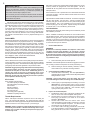
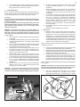
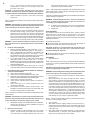
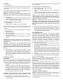
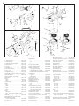
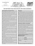
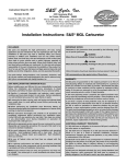
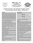
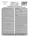
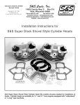
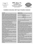
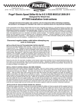
1
Instruction Sheet No.100
S&S Cycle, Inc.
Revised 1-12-99
14025 County Hwy. G P.O. Box 215
Viola, Wisconsin 54664
Copyright ©, 1998, 1999
by S&S Cycle, Inc.
All rights reserved. Printed in the U.S.A.
Phone 608-627-1497
Fax 608-627-1488
Customer Service - [email protected]
Technical Assistance - [email protected]
Installation and Jetting Instructions for S&S Super B Series Carburetor
SAFE INSTALLATION AND OPERATION RULES:
Before installing your new S&S Super carburetor it is your
responsibility to read and follow the installation and
maintenance procedures in these instructions and follow the
basic rules below for your personal safety.
● Gasoline is extremely flammable and explosive under
certain conditions and toxic when breathed. Do not smoke.
Perform installation in a well ventilated area away from open
flames or sparks.
● If motorcycle has been running, wait until engine and
exhaust pipes have cooled down to avoid getting burned
before performing any installation steps.
● Before performing any installation steps disconnect
battery to eliminate potential sparks and inadvertent
engagement of starter while working on electrical
components.
● Read instructions thoroughly and carefully so all
procedures are completely understood before performing
any installation steps. Contact S&S with any questions you
may have if any steps are unclear or any abnormalities occur
during installation or operation of motorcycle with S&S carb
on it.
● Consult an appropriate authorized H-D service manual
for correct disassembly and reassembly procedures for any
parts that need to be removed to facilitate installation.
● Use good judgement when performing installation and
operating motorcycle. Good judgement begins with a clear
head. Don't let alcohol, drugs or fatigue impair your
judgement. Start installation when you are fresh.
● Be sure all federal, state and local laws are obeyed with
the installation.
● For optimum performance and safety and to minimize
potential damage to carb or other components, use all
mounting hardware that is provided and follow all installation
instructions.
● To prevent possible engine flooding and overspill of
gasoline on surrounding area which is a fire hazard, make
sure float settings are correct and carburetor needle and
seat assembly works freely and shuts off supply of gasoline
after installation is completed. Always shut off fuel petcock
when engine is not running.
● Be sure all fuel lines, supply and overflow, are routed
correctly and fuel line clamps are in place and tightened.
Lines must not contact exhaust pipes or other extremely
hot surfaces where they could melt or leak and catch fire.
● Before starting engine and riding motorcycle, be sure
throttle opens and closes smoothly. Turn handlebars to left
and test throttle. Then, turn bars to right and test throttle. To
avoid possible loss of control of motorcycle and potential
personal injury to yourself or others due to throttle sticking in
open position, throttle must work smoothly and return to a
fully closed position when hand is removed from throttle grip.
● Motorcycle exhaust fumes are toxic and poisonous and
must not be breathed. Run motorcycle in a well ventilated
area where fumes can dissipate.
IMPORTANT NOTICE:
Statements in this instruction sheet preceded by the following
words are of special significance:
WARNING
Means there is the possibility of injury to yourself or others.
CAUTION
Means there is the possibility of damage to the carburetor
or motorcycle.
NOTE
Other information of particular importance has been placed in
italic type.
S&S recommends you take special notice of these items.
WARRANTY:
All S&S parts are guaranteed to the original purchaser to be
free of manufacturing defects in materials and workmanship for a
period of six (6) months from the date of purchase. Merchandise
that fails to conform to these conditions will be repaired or replaced
at S&S’s option if the parts are returned to us by the purchaser
within the 6 month warranty period or within 10 days thereafter.
In the event warranty service is required, the original purchaser
must call or write S&S immediately with the problem. Some
problems can be rectified by a telephone call and need no further
course of action.
A part that is suspect of being defective must not be replaced by a
Dealer without prior authorization from S&S. If it is deemed
necessary for S&S to make an evaluation to determine whether
the part was defective, a return authorization number must be
obtained from S&S. The parts must be packaged properly so as
to not cause further damage and be returned prepaid to S&S with
a copy of the original invoice of purchase and a detailed letter
outlining the nature of the problem, how the part was used and the
circumstances at the time of failure. If after an evaluation has
been made by S&S and the part was found to be defective, repair,
replacement or refund will be granted.
ADDITIONAL WARRANTY PROVISIONS:
(1) S&S shall have no obligation in the event an S&S part is
modified by any other person or organization.
(2) S&S shall have no obligation if an S&S part becomes defective
in whole or in part as a result of improper installation, improper
maintenance, improper use, abnormal operation, or any other
misuse or mistreatment of the S&S part.
(3) S&S shall not be liable for any consequential or incidental
damages resulting from the failure of an S&S part, the breach of
any warranties,the failure to deliver, delay in delivery, delivery in
non-conforming condition, or for any other breach of contract or
duty between S&S and a customer.
(4) S&S parts are designed exclusively for use in Harley-Davidson
motorcycles. S&S shall have no warranty or liability obligation if an
S&S part is used in any other application.
2
IMPORTANT NOTE:
Please read these instructions carefully before attempting to install
or tune your carburetor. Answers to nearly all your questions and
problems can be found in this way. If you still have a problem, you
may call for technical help at (608) 627-1497.
Do not call us if you have not read your instruction sheet. We at S&S
feel we have designed and manufactured a quality carburetor and we
stand behind our products.
Introduction
S&S Super B carburetor is designed exclusively for Harley-Davidson
Big Twin and Sportster engines. It is a butterfly type carb with a fully
adjustable idle mixture screw and changeable mid range and high speed
jets. This carburetor does not have an accelerator pump nor a
conventional choke, but utilizes a mixture enrichment device for starting.
The Super B has a 1 7⁄8" (47.6mm) throat at the butterfly and a 1 9⁄16"
(39.6mm) venturi and is identified by an "B" cast into the throttle return
spring side of the carb body below the cast in wording "S&S SUPER".
The Super B is recommended for use on any displacement Big Twin or
Sportster.
DISCLAIMER:
S&S parts are designed for high performance, off road, racing applications
and are intended for the very experienced rider only. The installation of
S&S parts may void or adversely effect your factory warranty. In addition
such installation and use may violate certain federal, state, and local
laws rules and ordinances as well as other laws when used on motor
vehicles used on public highways, especially in states where pollution
laws may apply. Always check federal, state, and local laws before
modifying your motorcycle. It is the sole and exclusive responsibility of
the user to determine the suitability of the product for his or her use, and
the user shall assume all legal, personal injury risk and liability and all
other obligations, duties, and risks associated therewith
Chrome Plating the Carburetor
NOTE - S&S does not recommend chrome plating the Super B carburetor.
Proper preparation to achieve a good chrome finish requires polishing
using buffing compounds. These materials invariably plug air and/or fuel
passageways and feed holes regardless of the precautions taken.
CAUTION - Plugged passageways and feed holes and the polishing
and chrome plating processes can alter operating tolerances
machined into the parts in critical areas. Additionally, pieces of
chrome may break off and plug a passageway which could
potentially affect the fuel mixture resulting in damage to the engine.
S&S voids any warranty if the carb body and/ or bowl is polished,
chrome plated or altered in any way.
Kit Contents
Each complete carb kit includes:
One S&S Super B gas carburetor
One S&S teardrop air cleaner assembly
One manifold
Mounting hardware
Fuel line and clamps
Two extra main jets
Voes tubing (when applicable)
Installation and jetting instructions
Throttle Requirements
NOTE - S&S Super B carburetor requires the use of a two cable, pull
open - pull closed throttle assembly. Any chassis including 1980 and
earlier stock H-D models equipped with a single cable throttle mechanism
requires conversion to a two cable, pull open - pull closed type.
WARNING - Single, braided wire cable throttle mechanism can not
mechanically close throttle. If throttle inadvertently sticks in open
position, loss of control of motorcycle and personal injury to you
or others may result.
S&S offers an optional two cable throttle assembly designed to convert
most any chassis not equipped with a two cable system. This kit is
available with 48" long cables and can be ordered separately. See the
description below.
Stock models from 1981 to present have a two cable throttle and should
not require conversion. The stock cables on these chassis can be used
but must be modified.
Optional S&S Two Cable Throttle Conversion Kit - for chassis not equipped
with two cable throttle - Part #19-0229 - Includes complete throttle
assembly with grips for both bars and two 48" (cable housing length)
cable assemblies. Fits 1" O.D. handlebars and can be used on most
chassis requiring up to 48" long cables. Special bushings are available
for use with older 7⁄8" O.D. handle bars, part #19-0235.
Carb Installation
Read instructions thoroughly before starting work to familiarize yourself
with installation procedure.
NOTE - Installation of S&S Super B carb kits on some models is easier
with gas tanks removed. Some owners may elect to perform installation
without removing gas tanks. This option has been left to discretion of
individual. If one elects to remove tanks or must disassemble any other
stock parts, S&S recommends he consult appropriate H-D service manual
for his model motorcycle for reference.
1.
Remove Old Carburetor
WARNINGS
● Gasoline is extremely flammable and explosive under certain
conditions and toxic when breathed. Do not smoke. Perform
installation in a well ventilated area away from open flames or sparks.
● If motorcycle has been running, wait until engine and exhaust
pipes have cooled down to avoid getting burned before performing
any installation steps.
A.
Disconnect battery and shut off fuel petcock.
WARNING - Unwarranted sparks and inadvertent engagement of starter
from working on electrical components can cause personal injury.
B.
2.
Remove existing air cleaner assembly, carburetor, manifold,
choke cable and any carburetor mounting hardware.
Check Idle Speed and Mixture Settings
A. Check idle mixture screw setting. Turn screw (See Picture 1)
clockwise closing it counting number of turns to fully closed position
setting should be 1 1⁄2 turns.
CAUTION - Closing idle mixture screw too tightly may cause
irreversible damage to needle and seating area in carburetor body.
B.
3.
Check engine rpm speed adjusting screw setting. Turn screw
(See Picture 1) counterclockwise until it no longer contacts
carb body. Next, turn it clockwise until it just recontacts body.
Then, continue turning additional 1⁄2 turn clockwise, slightly
opening throttle plate, part #11-2055.
Prepare Air Cleaner Backplate
A. Knuckles/Pans 1955 to 1965 - Press plugs, part #50-8312, into
holes "A" and "B" in air cleaner backplate. See Figure A.
B. Shovels 1966 to 1979 and Iron Head (IH) XLs 1957 to 1979 Press plugs, part #50-8313, into holes "D" in air cleaner
backplate. See Figure A.
C. Shovels 1980 to 1984 and IH XLs 1980 to 1985 - Screw
crankcase breather vent elbow fitting, part #50-8110, into hole
"A" in air cleaner backplate in Figure A. On 1983 and 1984
Shovels press plug, part #50-8312, into hole "B".
D. FL V2s 1984 to 1992 - Press plug, part #50-8312, into hole "B"
in air cleaner backplate. Screw crankcase breather vent elbow
fitting, part #50-8110, into hole "A". See Figure A.
3
E.
XL V2s 1986 to 1990 - Press plug, part #50-8312, into hole "A"
in air cleaner backplate. Screw crankcase breather vent elbow
fitting, part #50-8110, into hole "B". Picture 1
H.
I.
4.
Install New Manifold
NOTE - Whenever applicable, all carburetor mounting brackets and
hardware supplied in kit must be installed and used to secure carburetor
and air cleaner assembly or air horn (if used) rigidly to engine.
J.
CAUTIONS
● An improperly mounted carburetor could come loose from engine
resulting in air leaks, poor performance, and damage to carburetor
or other components.
● Incorrect combinations of mounting hardware may cause some
mounting bolts to bottom out in holes or inadvertently contact other
parts possibly causing damage to one or more engine and/or
carburetor components.
WARNING - If motorcycle were to fall over or sustain damage in a
collision or rider fall down, an improperly mounted carburetor could
break free causing an unwarranted release of gasoline to flood
surrounding area creating a fire hazard and potential personal injury
to you or others.
A.
B.
C.
D.
E.
F.
G.
Clean intake ports on cylinder heads to insure proper manifold
to head seal.
Install intake manifold provided. Point vacuum advance fitting
upward if it is equipped with one. Do not tighten manifold clamps
or flange bolts.
Pans - Loosen center crankcase stud nut between tappet blocks
and bolt bracket, part #16-0096, in place to connect bottom
carb manifold mounting hole to crankcases.
Shovels 1966 to 1982 - Bolt bracket, part #17-0092, to rear of
front rocker cover using 5⁄16-18 x 5⁄8" bolt, 5⁄16" flatwasher and 5⁄16"
lockwasher provided in kit. Do not tighten. End of bracket with
sharp bend goes toward rocker cover.
Shovels 1983 to 1984 - Loosen center crankcase stud nut
between tappet blocks and bolt bracket, part #16-0471, in place
to connect bottom carb manifold mounting hole to crankcases.
IH XLs - Bolt bracket, part #17-0093, to front tappet block using
5
⁄16 -18 x 1 1⁄4" bolt, 5⁄16" flatwasher and 5⁄16" lockwasher provided in
kit. Do not tighten. End of bracket with sharp bend goes toward
tappet block.
Bolt carb in place. Pan and 1983-'84 Shovel mounting bolts
measure 1" and 1 1⁄4" long - 1 1⁄4" bolt goes in bottom hole. Snug
mounting bolts. Do not final tighten.
CAUTION - If incorrect length mounting screws are used in
carburetor mounting holes, screws may bottom in mounting hole
or contact carb bowl causing damage to carb body and/or carb bowl.
K.
L.
5.
All engines except Pans and Shovels 1983 to 1984 - Install
air cleaner backplate using three 1⁄4-20 x 3⁄4" screw/washer
assemblies.
1966 to 1982 Shovels and all IH Sportsters - Bolt bracket to
air cleaner backplate through hole "B". See Figure A. Use
1
⁄4" flatwasher and locknut provided and snug all mounting
bracket bolts.
FL V2s 1984 to 1992 and XL V2s 1986 to 1990 - Bolt bracket,
part #17-0312, to air cleaner backplate through holes "D" using
two 1⁄4 -28 x 7⁄8" bolts, two 1⁄4 -28 nuts and 1⁄4" flatwashers
provided. Fill gap between bracket and cylinder heads using
shims provided in S&S shim kit, part #17-0314. Hold
backplate, bracket and shims in place with 5⁄16 -18 x 1" mounting
bolts and 5⁄16" flat and lock washers. Snug all nuts and bolts.
Do not final tighten.
Final tighten manifold mounting clamps and/or mounting
flange bolts.
Remove air cleaner backplate from carburetor.
Install Carb
A. Determine length of throttle cables required and shorten if
necessary. If outer cables are shortened, inner cables must
shortened also. Be sure to determine proper length and
resolder last 1 1⁄2” of inner cable before cutting. This will insure
cable strands do not separate. If cable lengths are correct and
are equipped with ball or barrel fittings, last 1 1⁄2" of inner cables
must be soldered before ends are cut off. Apply light coat of
lubrication to inner cables before reassembling.
NOTE - Consult H-D service manual for proper throttle disassembly and
reassembly procedures.
B.
C.
D.
Thread opening side throttle cable through upper throttle cable
housing boss and throttle cable clamp on throttle arm.
Repeat step B for closing side throttle cable. Cable with larger
diameter outer housing is used to close throttle and should be
positioned in lower boss on carburetor body.
Adjust throttle cable adjusters to remove excessive freeplay
and test throttle to be sure it opens and closes freely. Turn
handlebars to extreme left and open and close throttle, then
turn bars to extreme right and check throttle. If throttle binds,
loosen cable freeplay adjusters to put more freeplay in cables.
NOTE - Throttle must not bind and must snap shut to fully closed position
when released.
WARNING - If throttle does not return to fully closed position when
released, it may inadvertently stick open possibly causing loss of
control of motorcycle and personal injury to you or others.
E.
Enrichment Device
A
Bolt carb to intake manifold using two 3⁄8 -16 x 1" socket
cap screws provided in kit. Knuckle/Pan and 1983-'84
Shovel kits come with one 1" screw and one 1 1⁄4" screw.
D
E
Idle Mixture
C
Idle Speed
E
B
Picture 1
Figure A
4
The 1 1⁄4 " screw must go in bottom hole and is longer to
compensate for thickness of mounting bracket, part
#16-0096 or #16-0471.
CAUTION - If incorrect length mounting screws are used in
carburetor mounting holes, screws may bottom in mounting hole
or contact carb bowl causing damage to carb body and/or carb bowl.
petcock and wait 20 seconds. If gas runs out end of carb, turn
off petcock and check needle and seat.
NOTE - Fuel needle and seat assembly must completely shut off fuel
supply entering bowl. Fuel inlet fitting to bowl sealing area and/or fuel
line connections must not leak.
Recheck throttle to be sure it opens and closes freely.
See step D.
CAUTION - Unwarranted gasoline leaking by inlet needle may flood engine
causing damage to components.
NOTE - Throttle must not bind and must snap shut to fully closed position
when released.
WARNING - Unwarranted gasoline leaks , at fuel line connections
and/or past inlet needle may flood engine and overflow on
surrounding area creating fire hazard.
F.
WARNING - If throttle does not return to fully closed position when
released, it may inadvertently stick open possibly causing loss of
control of motorcycle and personal injury to you or others.
B.
C.
G.
Apply thin coating of oil to fuel inlet fitting and slip end of fuel
line with 90° bend on fitting. Clamp in place. Slip stock H-D
protective fuel line covering over fuel line if equipped and
position where contact with other engine parts might take
place. On early models equipped with bottom manifold screw
wire fuel line support guide, use guide whenever possible.
Connect fuel line to gas tank petcock using clamp provided.
If needle and seat assembly works properly, install element
and air cleaner cover using three 1⁄4 -20 x 1" mounting screws.
Fill gas tank.
Carb Operation
This carburetor does not have conventional choke. Instead, a mixture
enrichment device, part #11-2084, is used for starting. This device
utilizes separate air and fuel pickup passageways. This device is
engaged by raising the lever on top left side of carburetor and turning it
slightly (See Picture 1).
WARNING - Fuel line must be clamped securely and not contact
any hot surfaces such as exhaust pipes where it could melt and
catch fire.
Enrichment Device Notes:
● Enrichment pickup tube located directly below fast idle plunger is
pressed into carburetor body and must not be removed.
6.
CAUTION - Removal of enrichment/fast idle pickup tube from
carburetor body may alter hole size in carb body and cause
irreversible damage to carburetor.
7.
Install Air Cleaner Backplate
A. Mount air cleaner backplate on carb using three 1⁄4 -20 x 3⁄4"
screw/washer assemblies through holes "C". See Figure A.
B. 1966 to 1982 Shovels and IH Sportsters - Bolt bracket to air
cleaner backplate through hole "B". See Figure A. Use 1⁄4"
bolt, flatwasher and locknut provided and snug all mounting
bracket bolts. Final tighten all mounting bracket bolts.
C. FL V2s 1984 to 1992 and XL V2s 1986 to 1990 - Bolt air cleaner
backplate bracket to cylinder heads with 5⁄ 16 -18" bolts,
flatwashers and lock washers. Fill gap between cylinder heads
and mounting bracket with shims as previously determined in
manifold installation step.
D. Shovels and Sportsters 1980 to 1985 and all V2s - Connect
crankcase breather hose to air cleaner backplate hose fitting.
Reassemble Anything that Was Disassembled for Installation
and Final Check Installation
A. Check carb to manifold mounting bolts.
B. Check carb to air cleaner backplate mounting screws.
C. Check carb mounting bracket to head or to tappet block mounting
bolts and air cleaner backplate to heads mounting bolts.
D. Check fuel line connections and routing.
E. Check vacuum operated advance ignition connections if
applicable.
F. Check crankcase to air cleaner backplate vent hose
connections if applicable.
G. Test throttle to be sure it opens and closes freely. Turn
handlebars to extreme left and open and close throttle, then
turn bars to extreme right and check throttle.
● Enrichment device may be removed for cleaning purposes, but must
not be disassembled any further.
Cold Starts
1.
NOTE - When motorcycle is not running, fuel shutoff valve should always
be turned off to prevent possible leakage should needle and seat not
work properly.
CAUTION - Unwarranted gasoline leaking by inlet needle may flood
engine causing damage to components.
WARNING - Unwarranted gasoline leaking past inlet needle may flood
engine and overflow on surrounding area creating fire hazard.
2.
3.
NOTE - Throttle must not bind and must snap shut to fully closed position
when released.
WARNING - If throttle does not return to fully closed position when
released, it may inadvertently stick open possibly causing loss of
control of motorcycle and personal injury to you or others.
H.
8.
Reassemble anything that was disassembled for installation.
Consult your H-D service manual for installation of parts not
covered in these instructions.
Bolt on Air Cleaner Cover
A. Check fuel needle and seat assembly to be sure it works
properly. Fill gas tank with just enough fuel to test system.
Lean motorcycle over towards carburetor side, turn on fuel
Open fuel petcock.
Pull enrichment device handle part #0084, to raised position
(See Picture 1).
With throttle closed, kick engine through three times. Electric
start models go to step #4 and engage electric starter. For colder
weather, 50° and below, or for engines with long duration cams, it
may be necessary to prime engine several additional kicks. Low
compression and/or cams with long duration and extreme overlap
may reduce cranking compression to where intake vacuum is low.
Low vacuum reduces draw through enrichment device making it
difficult to get a sufficient prime . If this appears to be the case,
close butterfly completely by turning engine rpm adjustment screw
on throttle arm, part #11-2148, one turn. This will force all intake
vacuum to draw through enrichment device during priming. After
initial startup, turn rpm screw to original idle position.
NOTE - If throttle is opened during priming, enrichment device will not
provide a rich enough starting mixture.
4.
5.
6.
Turn on ignition.
With throttle closed or slightly cracked, kick engine through. If
engine fails to start immediately, slowly crack throttle (just enough
to barely open butterfly) and continue to kick or engage starter
until engine fires.
After engine starts, leave enrichment device on until engine has
warmed sufficiently. If necessary, jockey throttle slightly to keep
engine running. Motorcycle may now be ridden.
5
Hot Starts
1.
Open fuel petcock.
NOTE - When motorcycle is not running, fuel shutoff valve should always
be turned off to prevent possible leakage should needle and seat not
work properly.
CAUTION - Unwarranted gasoline leaking by inlet needle may flood
engine causing damage to components.
WARNING - Unwarranted gasoline leaking past inlet needle may
flood engine and overflow on surrounding area creating fire hazard.
2.
3.
4.
Turn on ignition.
With throttle closed, kick engine through or engage electric starter.
If engine fails to start immediately, open throttle slightly and continue
to kick or engage starter until engine fires.
Troubleshooting Tips - engine will not start:
1. Fuel supply empty.
2. Weak or no spark - discharged battery or faulty magneto.
NOTE - We do not recommend use of magnetos as magneto in poor
condition and/or improperly serviced can adversely affect starting
conditions.
3.
4.
5.
6.
7.
Plug gap too wide - we use .022 to .025 plug gap on point type
ignition engines.
Improper ignition timing.
Tight tappet adjustment.
Improper idle mixture and/or engine rpm setting. See "Adjusting
Carburetor - Idle Circuit".
Enrichment device well feed hole in bowl plugged. Clear hole with
forced air.
CAUTION - Do not use wire or drill to clear hole. If size is altered,
starting system will be changed resulting in irreversible damage to
carburetor bowl.
WARNING - Compressed air and particles dislodged using
compressed air are harmful to eyes and body. Wear protective
goggles when using compressed air and always direct air stream
away from body parts such as hands and eyes and other people
near you.
8.
Improper diagnosis of rich or lean mixture condition. If engine
backfires in carb, this usually indicates lean condition, and engine
must be reprimed. If there is no response after three kicks or if
engine pops in exhaust pipes, it usually means mixture is too rich.
Leave switch on and slowly open throttle 1⁄4 turn with each successive
kick until engine fires.
Adjusting Carburetor
Idle Circuit
Idle mixture screw, part #11-2354, regulates air/fuel mixture at idle
speeds. Throttle stop/engine rpm adjustment screw is located on throttle
arm, part #11-2148 (See Picture 1). S&S adjusts both screws during
assembly to settings that should work for initial start-up after installation.
1. Start engine and run until slightly warm (approximately 1 to 2
minutes).
2. Initially adjust engine rpm to idle at approximately 800-1000 rpm.
3. Turn idle mixture screw, part #11-2354, clockwise, leaning mixture,
until engine starts to die. Next, turn screw counterclockwise,
richening mixture, until engine starts to die. When screw is positioned
about halfway between these points, or about 1⁄4 to 1⁄2 turn out from
lean side of adjustment range, it is set correctly.
NOTE - Whenever intermediate jet change is made, idle mixture screw
must be readjusted.
Troubleshooting Tips - engine will not idle:
1. Improper idle mixture and/or engine rpm setting.
2. Intake manifold air leak.
3. Sticky timing automatic advance mechanism or other ignition
problem.
4. Foreign material in air and/or gas passageway in carb causing flow
restriction to idle/intermediate circuit. Clear holes with forced air.
CAUTION - Do not use wires or drills to clear holes. If sizes are
altered, air/fuel ratios of idle and intermediate systems will be
changed resulting in poor performance and irreversible damage to
carburetor body and intermediate jet.
WARNING - Compressed air and particles dislodged using
compressed air are harmful to eyes and body. Wear protective
goggles when using compressed air and always direct air stream
away from body parts such as hands and eyes and other people
near you.
5.
Enrichment device plunger not sealed causing excessively rich
mixture. Be sure device is fully disengaged (in down position)
allowing plunger to bottom out and seal passageway. CURE: Lift
and release plunger several times, letting it "snap" to closed position
to fully seat and seal against carb body.
Intermediate System
Intermediate range is used most often under normal riding conditions
and begins right off idle and operates up to approximately 3000-3500
rpm or 50 to 60 mph depending on gearing. Therefore, close attention
must be paid to jetting intermediate range to achieve optimum
performance and best gas mileage. Intermediate jet, part #11-7100, is
reached by removing float bowl assembly (See Picture 2). Actual size of
intermediate jet installed in carburetor is indicated on tag attached to
carb and/or on printed label on carburetor packing box. Keep this
information handy for future reference.
1. Road test bike, being sure to ride it far enough to bring engine and
oil to normal operating temperature.
2. Re-check idle mixture adjustments to be sure setts are correct with
fully hot engine.
3. Check throttling characteristics by slowly rolling throttle on after
maintaining steady speed. This should be done at several rpm levels
or speeds of 30,40, and 50 mph. If "popping" or "spitting" (backfiring)
occurs in air cleaner, this indicates lean condition and intermediate
jet must be changed to next larger size (size is stamped on end or
side of jet).
4. Change jet accordingly and repeat road test. Smallest intermediate
jet that eliminates this condition should provide best gas mileage.
Notes on Intermediate Jetting:
● See "Notes on Intermediate and High Speed Jetting" at end of "High
Speed Circuit or Main Jet" section of these instructions.
● Whenever intermediate jet change is made, idle mixture screw must
be readjusted.
● Gas mileage and throttling characteristics may also be determined
by personal riding habits. Snapping throttle open in lower rpm ranges is
inefficient and uneconomical because intermediate system is bypassed.
When intermediate system is bypassed engine momentarily goes lean
(from lack of fuel from intermediate) then rich (from excessive fuel from
main). In effect, engine uses more fuel than it should. Engine will respond
better and be more efficient if throttle is rolled on and intermediate has
time to properly engage.
High Speed Circuit or Main Jet
CAUTION - Closing idle mixture screw too tightly may cause
irreversible damage to needle and seating area in carburetor body.
High speed circuit begins around 3000-3500 rpm or 55-60 mph and
operates to maximum attainable speed. Main jet, part #11-7200, is
reached by removing bowl plug, part #11-2090.
4.
5.
NOTE - S&S has special main jet tool, part #53-0452, which is handy for
changing main jets.
Readjust engine rpm to idle at approximately 800-1000 rpm.
After engine and oil have reached normal operating temperature,
repeat steps 3 and 4.
6
Size of metering hole in main jet in thousandths of an inch is stamped on
end of jet. Size of main jet installed in new carburetor from S&S is indicated
on tag attached to carb and/or on printed label on carburetor packing
box. Keep this information handy for future reference.
Main jet size is best determined by testing at drag strip, because
maximum miles per hour and rpm are best indicators of actual
horsepower engine is developing. S&S recommends that high speed
jetting be done at drag strip.
Intermediate Jet
Dragstrip Procedure
1.
2.
3.
4.
5.
Warm up engine enough to begin testing.
Make run noting engine rpm and final speed.
Increase or richen main jet size .004 larger and make second run.
Again, note rpm and final speed.
Continue procedure until mph falls off.
Decrease or lean main jet size by .002 to gain best (maximum) rpm
and mph. When making runs, do not strive for ETs but for consistent
miles per hour.
Main Jet
Street Procedure
Picture 2
S&S uses what we call "RPMing" method to determine correct main jet
size. Hard acceleration is evaluated up to the rpm where horsepower
peaks and begins to taper off and gear shift occurs. Main jet that makes
engine accelerate strongest or rpm through gears quickest is correct.
1. Warm engine to operating temperature.
2. Accelerate rapidly through gears noting how quickly and smoothly
engine reaches rpm level where pull of engine begins to fade and
gear shift occurs.
3. If engine backfires in carburetor and sputters or "breaks up" and/or
dies during acceleration, increase or richen main jet size .004 larger
and road test again. Note engine smoothness and how easily engine
reaches rpm level where gear shift occurs.
4. If engine runs flat and sluggish or "blubbers" or will not take throttle,
decrease or lean main jet size .004 smaller and road test again.
Note engine smoothness and how easily engine reaches rpm level
where gear shift occurs.
5. Continue changing main jets until one is selected that makes engine
accelerate or rpm through gears most quickly and smoothly. Our
experience has taught us that a jet about .006 smaller (leaner) than
correct one will make engine "break up" and quit. A jet about .006
larger (richer) will make engine "blubber" and miss.
Troubleshooting Tips for Intermediate & High Speeds - Engine
will not run at steady speed or rpm:
1. Restriction in fuel supply system - gas tank vent plugged, gas petcock
too small (Stock H-D petcock is usually adequate, but might require
running on "reserve" to provide adequate supply for big inch engines.
Alternative - switch to Pingel brand high flow petcock.), needle and
seat not working properly. See "General Information".
2. Faulty ignition system - fouled plugs, worn points, defective coil or
solid state module, improper ignition timing.
3. Incorrect intermediate and/or high speed jetting. See "Adjusting
Carb - Intermediate System" and "High Speed Circuit or Main Jet".
4. Foreign material in air and/or gas passageway in carb causing flow
restriction. Clear holes with forced air.
CAUTION - Do not use wires or drills to clear holes. If sizes are
altered, air/fuel ratios of idle and intermediate systems will be
S&S Super B Jetting Chart
Engine
Displacement
Stock
CH Strokers
Stock Big Twin
Strokers
Mild Strokers 84" or Larger
Idle Mixture
Screw Setting
1 1⁄4 to 1 3⁄4
turns
1 1⁄4 to 1 3⁄4
turns
1 1⁄4 to 1 3⁄4
turns
Intermediate Jet
.265 to .032
.0295 to .033
.031 to .036
Main Jet
.062 to .070
.068 to .076
.072 or Larger
changed resulting in poor performance and irreversible damage to
carburetor body and intermediate jet.
WARNING - Compressed air and particles dislodged using
compressed air are harmful to eyes and body. Wear protective
goggles when using compressed air and always direct air stream
away from body parts such as hands and eyes and other people
near you.
5.
No air cleaner used or air cleaner used is brand other than S&S.
Some air cleaner designs restrict air flow so that carb cannot draw
air freely as needed. Also, other air cleaners may obstruct bowl
vent hole on inlet end of carb and change bowl air pressure.
NOTE - Bowl vent hole passageway leads to cavity above fuel in bowl
and is designed to equalize bowl pressure and atmospheric pressure. If
high or low bowl pressure relative to atmospheric pressure develops,
engine may run erratically.
6.
Air horn used without shrouding bowl vent on end of carburetor body.
NOTE - Bowl vent should be shrouded to insure uniform atmospheric air
pressure between cavity above fuel level in bowl and area outside
carburetor body. If high or low bowl pressure relative to atmospheric
pressure develops, engine may run erratically.
7.
8.
9.
Valve train defect - bad valves, sticky valves, bad or broken springs,
improper clearances for high lift cam or, defective camshaft with
improper valve timing.
Too much gear - not enough horsepower to pull gearing.
See "Notes on Intermediate and High Speed Jetting" below.
Notes on Intermediate and High Speed Jetting:
● Carburetor jetting and spark plug color - While spark plug color
may be used to help determine carburetor jetting, S&S recommends
that our instructions be used as primary jetting guide and that plug
color indications be used only as secondary aid. We have found that
different brands of gasoline, gasoline additives, engine heat (due to
ignition timing), and type of plugs and heat range used distort plug
color drastically making plug reading difficult for average tuner. Also,
new plugs usually require road test of 10 miles or more to properly
develop color which means that quarter mile tests may not be long
enough and hence, not always a good indication of carb jetting. It is
best to use proven spark plug combinations and to consult spark plug
manufacturer if you have questions. If one desires to become more
proficient at plug reading, Champion Racing Division has a very
informative booklet which may be helpful. For details, write:
Champion Spark Plug Co.
PO Box 910
Toledo, OH 43601
7
● If bike is used exclusively on drag strip where engine temperatures
vary, slightly richer jets may be necessary to gain best performance.
Larger jets or richer mixtures will enable one to run colder engine which
is sometimes desirable. This is best determined by experimentation with
particular engine to be used.
● Cams and exhaust systems can make some engines difficult to
carburate. We have found that certain cams and exhaust systems will
cause poor performance at a specific rpm, and attempts to carburate to
correct this condition usually destroys carburetion over the balance of
the range. A combination of cam overlap, reversion, and back pressure,
or even lack of back pressure can cause mixture dilution at certain engine
rpms. This dilution will cause engine roughness or misfiring when engine
is held in this range.
● Drag pipes - For Knucklehead, Panhead, Shovelhead, and Ironhead
Sportster engines, 1-7/8" O.D. drag pipes with straight cutoff end 28" to
30" long will work well with almost any camshaft and/or other performance
modification. 2" O.D. drag pipes are not recommended for any
applications except very large competition engines. The use of drag
pipes is not recommended for Evolution motors in street applications.
● Mufflered systems: A very good , economical street exhaust system
for V2 and earlier engines as well, consists of the stock head pipes with
the cross-over tube and a set of low restriction mufflers. This system will
typically produce 10 hp more than drag pipes in the midrange. This
makes an ideal system for the street since the midrange is where the
vast majority of normal driving occurs.
NOTES - General Information
● Carburetor body has seven drilled passages that are permanently
sealed with drive plugs. Do not attempt to remove these plugs as
irreversible damage to carburetor may result.
● If throttle arm, part #11-2148, is removed from throttle shaft, it
must be reinstalled in wide open position with throttle plate, part
#11-2055, at 90˚ to the fully closed position. See Figure B.
● Throttle plate, part #11-2055, should be checked annually for signs
of wear. Replace if necessary. If carb body needs repair, use S&S repair
kit, part #11-2903, #11-2914 or #11-2909. If throttle plate is removed, be
sure to reinstall it correctly. See Figure C. Edges of plate must fit flat
against carb throat.
● To insure proper seal in needle and seat assembly, float hinge, needle
lift and needle must work freely and must not bind. If problem is suspected,
remove bowl and check float movement. If obvious misalignment, binding
or sticking occurs, remove and straighten and reinstall to attain free
movement. Reset float level and double check for free movement. Float
must not contact bowl gasket.
● Normal float setting is 1⁄8" and should be measured at end of float
opposite needle and seat assembly. To check this measurement, turn
bowl upside down and measure from bowl gasket surface up to float.
● On rubber mounted engines, set float where it just misses bowl gasket,
part #11-2086, when fuel inlet needle is fully closed and spring in needle
is compressed. See Figure D. To check, remove bowl and raise float
until needle is in closed position and spring in top of needle is compressed.
Highest part of float should be slightly (approximately 1⁄32") below bowl
gasket surface. Float must not contact bowl gasket.
● When motorcycle is not running, fuel shutoff valve should always be
turned off to prevent possible leakage should needle and seat not work
properly.
● If an air horn is desired for drag racing, use S&S part #17-0042. Be
sure to shroud bowl vent.
● If you feel you have marginal fuel delivery through your stock petcock,
S&S recommends you try Pingel petcock, part #6211C (requires nut
#2001C), which fits most Big Twins or Pingel #5211C (also requires nut
#33-2001) which fits most Sportsters . Tests conducted at S&S have
shown Pingle petcocks to provide more than adequate fuel supply. If
you require an in line fuel filter, use Pingel #L1BLK1BLK40G, if room
permits (filter is 3" long and anodized black), or #S1P1P4OG, if room
doesn't permit (filter is 1 1⁄2" long and polished aluminum). Pingel's address
is:
Pingel Enterprise, Inc.
2076 C 11th Ave.
Adams, WI 53910
Phone: 608-339-7999 Fax: 608-339-9164
As a convenience to our customers S&S stocks these Pingel parts.
S&S part #19-0453 - Pingel petcock #5211C for Big Twins
S&S part #19-0454 - Pingel petcock #31-6011 for Sportsters
S&S part #19-0455 - Pingel nut #33-2001
S&S part #19-0456 - Large Pingel filter #L1BLK1BLK40G
S&S part #19-0457 - Small Pingel filter #S1P1P4OG
IMPORTANT NOTE:
We at S&S feel we have designed and manufactured a quality carburetor
and will stand behind this product. If you have questions or problems
refer to the instruction sheet. Answers to nearly all your questions can
be found in the instructions. If you still have a problem, you may call for
technical help at (608) 627-1497. However, do not call us until you have
read your instruction sheet.
S&S also has a complete carburetor repair and/or rebuilding service where
you can get quality work at a fair price. If you are not properly equipped
to take this carburetor apart and repair it and do not have a qualified local
repair shop available, we recommend you call for a return authorization
number and send it to us with a detailed note outlining any problems you
may have and any repairs you want performed so it can be serviced
correctly.
Bevels must be at angles shown by
arrows when installing plate.
Float just below gasket surface
(aproximately 1⁄32").
Spring in needle
fully compressed.
1
2
3
Arrow 1: Throttle plate horizontal.
Arrow 2: Throttle arm against stop.
Arrow 3: Throttle arm set screw.
Figure B
Figure C
Figure D
8
36
9
37
39
38
41
7
2
35
9
8
5
1
10
36
3
42
36
4
48
11
43
6
32
34
13
47
49
36
12
46
45
14
50
15
74 74
73
74
77
16
75
74
52
72
51
16
75
76
64
53
17
62
71
54
17
70
69
67
68
65
61
66
63
Style C
64
64
18
18
69
19
65
Style B
21
19
78
60
20
20
20
64
55
57
56
63
23
59
1. Throttle return spring ...................................... Part #11-2082
2. Throttle plate screw ........................................ Part #50-0029
3. Throttle shaft - comes w/2 #50-0029 .............. Part #11-2083
4. Throttle shaft bushing - for repair only ............ Part #11-2134
5. Enrichment device .......................................... Part #11-2084
6. Carb body ....................................................... Part #11-2081
7. Idle mixture screw ........................................... Part #11-2354
8. Idle mixture screw spring ................................ Part #11-2052
9. Oring - 1-7/8" .................................................. Part #50-8013
10. Throttle plate - 1-7/8" ...................................... Part #11-2055
11. Throttle arm assembly - two cable type .......... Part #11-2148
12. Intermediate jet - state size – state size – see jet section
13. Main discharge tube ....................................... Part #11-2085
14. Main jet - state size – see jet section
15. Bowl gasket .................................................... Part #11-2086
16. Float
style C ............................................................. Part #11-2187
style B ............................................................... not available
17. Float retaining pin ........................................... Part #11-2069
18. Bowl
style C ............................................................. Part #11-2188
style B .............................................................. not available
19. Needle
Style C ............................................................ Part #11-2195
style B ............................................................. Part #11-2095
20. Seat
styles B & C .................................................... Part #11-2065
style C, – threaded seat, not available, see #80
21. Bowl plug ........................................................ Part #11-2090
22. Bowl screw ..................................................... Part #50-0034
23. Gas inlet fitting , 90°- not available, see #80
32. Knuckle/Panhead manifold
1-7/8", for o-ring style heads ........................... Part #16-1100
35. 1" spacer - 1-7/8" ............................................ Part #16-0057
36. Manifold screw
1" .................................................................. Part #50-0161
1-1/4” ............................................................ Part #50-0162
2" .................................................................. Part #50-0164
2-1/4" ............................................................ Part #50-0165
37. Oring - for oring manifold .............................. Part #16-0237
38. Band- for rubberband manifold ..................... Part #16-0238
39. Manifold - Shovel & IH XL
1-7/8", o-ring style, stock length .................... Part #16-1200
1-7/8", rubberband style, stock length ........... Part #16-1300
1-7/8", rubberband style w/ VOES ignition, stock length ......
Part #16-1400
41. Manifold clamp
o-ring style .................................................... Part #16-0230
rubberband style ........................................... Part #16-0231
42. Lock nut, 5/16-18 .......................................... Part# 50-5021
43. Flat washer, 5/16-x1/16 ................................ Part# 50-7034
44. Adjustable support bracket ........................... Part #16-0471
46. Manifold o-ring - V2 ...................................... Part #16-0236
47. Manifold flange, all V2s
Front ............................................................. Part #16-0232
Rear .............................................................. Part #16-0233
48. Support bracket screw, 5/16-18x1" ............... Part #50-0108
49. Manifold - V2
1-7/8", for XL V2s, stock cyl length ............... Part #16-1600
1-7/8", for FL V2s, stock cyl length ................ Part #16-1608
50. Support bracket - Panhead ........................... Part #16-0096
51. Flatwasher, 3/8", special ............................... Part #50-7053
52. Air horn - comes w/3 #50-0071 ..................... Part #17-0042
53. Air cleaner assembly - for all engs., w/o mtg.bracs. .............
...................................................................... Part #17-0099
54. Air horn screw ............................................... Part #50-0071
55. Air cleaner cover screw ................................ Part #50-0072
56. Air cleaner cover ........................................... Part #17-0078
57. Air cleaner element ....................................... Part #17-0079
58. Air cleaner backing plate ............................... Part #17-0080
59. Air cleaner support bracket - '57-'85 XL ........ Part #17-0093
60. Vent hose connecter nipple ............................ Part #50-8111
61. Vent hose - 3/8' ID x 6" ................................. Part #17-0113
62. 90° elbow fitting ............................................ Part #50-8110
63. Support bracket bolt - 1/4-28 x 7/8" .............. Part #50-0074
64. Flatwasher, 1/4" ............................................ Part #50-7021
65. Air cleaner backplate screw .......................... Part #50-0073
66. Air cleaner gasket ......................................... Part #17-0196
67. Allen head plug - 1/8-27 ................................ Part #50-8312
68. Mounting hole plug ....................................... Part #50-8313
69. Support bracket locknut - 1/4-28 x 7/8" ......... Part #50-5010
70. Air cleaner support bracket '84 - '91 V2 FL & '86 - '90 V2 XL
...................................................................... Part #17-0312
71. Support bracket screw
5/16-18 x 1-3/4" ............................................. Part #50-0111
5/16-18 x 1-1/2" ............................................ Part #50-0109
5/16-18 x 1-1/4" ............................................ Part #50-0110
72. Lockwasher - 5/16" ....................................... Part #50-7032
73. Support bracket - V2 ..................................... Part #50-7053
74. Shim
5/16" x .020" ................................................. Part #50-7038
5/16" x .030" ................................................. Part #50-7039
5/16" x .040" ................................................. Part #50-7040
5/16" x .100" ................................................. Part #50-7041
5/16" x .125" ................................................. Part #50-7042
75. Shim
5/16" x .250" ................................................. Part #50-7043
5/16" x .550" ................................................. Part #50-7045
76. Shim kit - comes w/2 ea. #50-7038, #50-7039,#150-7040,
#50-7041 & 4 ea. #50-7042 .......................... Part #17-0314
77. Shim kit - comes w/2 #50-7043 & 2 #50-7045
...................................................................... Part #17-0313
78. Air cleaner support bracket - '66-'82 FL ........ Part #17-0092
80. Fuel line w/90° bend - use w/#11-2065, not shown
...................................................................... Part #19-0475