1
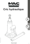
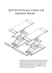
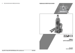
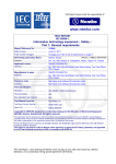
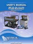
Contains all equipment needed to safely lift, support and work beneath a vehicle: 2T Trolley Jack 2T Axle Stands 5 Piece Lifting Kit Padded Car Creeper Wheel Wrench with 17/19 mm socket Steel Wheel Chocks 2 Tonne Lifting Capacity Lifting range 14 cm to 34 cm (5½” to 13⅜”) Short wheel base jack 32 cm Instruction Manual Item Code: 334091 INTRODUCTION Please read this manual before you use your lifting kit and ensure you understand its operation and the safe procedures to be observed. Ensure this manual is retained for future reference and that new users of this product read and understand the content before they use the lifting kit. GUARANTEE This product is guaranteed by Halfords against manufacturing defects for a period of 12 months from the date of purchase. This does not affect your statutory rights. Should you experience a problem please return the product, together with this manual and your receipt, to your nearest Halfords store. 2 TONNE HYDRAULIC TROLLEY JACK SHORT WHEEL BASE PRIOR TO OPEARATION Air may become trapped in the hydraulic system during transit. To purge air: 1. Open release valve by turning handle counter clockwise. 2. Pump handle rapidly 4 full strokes. This will expel air that may have entered oil passages during transit. 3. Close release valve rotating handle clockwise and pump handle. 4. If lift arm raised, jack is ready for use. If not, repeat this procedure. WARNING Read, study and understand all warnings and operating instructions prior to use. Do not overload this jack beyond the rated capacity. This jack is designed for use only on hard level surfaces capable of sustaining the load. This is a lifting device only. The load must be supported immediately by other appropriate means. Do not move or dolly the vehicle while on the jack. Lift only on areas of the vehicles as specified by the vehicle manufacturer. Centre load on saddle prior to lifting. Some vehicles require an adaptor to properly engage the frame for lifting. Use vehicle manufacturers instructions on proper lifting. No alternations on the jack shall be made. Failure to heed these warnings may result in personal injury and/or property damage. FOR YOUR SAFETY AND TO PREVENT INJURY: Use Service Jack For Lifting Purposes ONLY Always Support Vehicle with Axle Stands. OPERATING INSTRUCTIONS IMPORTANT: Before attempting to raise a vehicle, check vehicle service manual for recommended lifting surfaces. 1. To raise load: Close release valve tightly by attaching jack handle to release valve and turning handle clockwise DO NOT OVERTIGHTEN. Position jack under load so that saddle will contact load firmly and load is centred so it cannot slip. Insert jack handle into the socket and pump up and down until saddle approaches the load. Once again check to see that saddle is correctly positioned. Raise load to desired height. Place axle stands of appropriate capacity under the vehicle. DO NOT CRAWL UNDER VEHICLE WHILE LIFTING VEHICLE OR PLACING OR REMOVING AXLE STANDS! Place axle stands at vehicle manufacturer’s recommended lift areas that provide stable support for the raised vehicle. OPERATING INSTRUCTIONS 2. To lower load: Open release valve VERY SLOWLY (by turning handle counter clockwise). When release valve is opened, saddle and load will be lowered. Lower the vehicle slowly so as not to shock load the axle stands. Once repairs are completed, raise vehicle enough to remove axle stands. Lower vehicle very slowly. Caution: Keep hands or feet away from the hinge mechanism of the jack. CARE AND MAINTENANCE INSPECTION Visual inspection should be made before each use of the jack, checking for leaking hydraulic fluid and damaged, loose or missing parts. If subjected to an abnormal load or shock. Any jack which appears to be damaged in any way, found to be badly worn, or operates abnormally MUST BE REMOVED FROM SERVICE. LUBRICATION All moving joints require lubrication often. Using a grease gun, grease the lift arm pivot shaft grease fitting until grease appears at the end of the shaft. Oil all lift arm linkages, front wheels and rear casters. MAINTENANCE IMPORTANT: When adding or replacing oil, always use a qualify hydraulic oil. DO NOT use brake fluid, transmission fluid, alcohol, glycerine, detergent motor oil, or dirty oil as improper fluid can cause serious internal damage to jack. To add oil: With saddle fully lowered and jack on level ground, remove filler plug (see Fig.1). Oil should be filled to level of oil filler plug hole. If low, add oil as needed. Maintenance and inspection: The owner and/ or user must maintain and inspect the jack in accordance with the manufacturer’s instructions. SPECIFICATIONS Description............................................... 2 Tonne Trolley Jack Short Wheel Base Model....................................................... T820033 Low height................................................ 14 cm (5½”) High height............................................... 34 cm (13⅜”) Wheelbase............................................... 32 cm Saddle diameter....................................... 5 cm Handle length........................................... 42.5 cm Base length.............................................. 45 cm Chassis width........................................... 20.6 cm Weight...................................................... 8.7 kg LINE DRAWING OF PRODUCT WITH DESCRIPTION OF PARTS Fig. 2 ITEM NO. 1 2 3 4 5 6 7 8 DESCRIPTION Front wheel assembly Saddle Handle fork Handle assembly Release valve Power unit assembly Rear caster assembly Lifting handle This jack contains no user serviceable parts. Any modification may render the jack unsafe EC DECLARATION OF CONFORMITY We, Halfords Limited, lcknield Street Drive, Redditch, Worcestershire, B98 0DE hereby declare that the machine described below is both in its basic design and construction and in the version marketed by us conforms to the relevant safety and health related requirements of the appropriate EC Directives. This declaration shall cease to be valid if modifications are made to the machine without our approval. Product: 2 Tonne Hydraulic Trolley Jack Short Wheel Base Sold as part of the 5 Piece Lifting Kit Model: T820033 Item Code 334091 Serial number:........................................... (to be entered by customer) Applicable EC Directive /Regulations: Machinery Directive 2006/42/EC as amended by Directive 2009/127/EC EN1494:2000 + A1:2008 Mobile or movable jacks and associated lifting equipment The Supply of Machinery (Safety) Regulations 2008 Statutory instrument 2008 No.1597 The Supply of Machinery (Safety) (Amendment) Regulations 2011 Statutory instrument 2011 No.2157 It is ensured through internal measures that series-production units conform at all times to the requirements of current EC Directives and relevant standards. Signed.................................................................... CHRIS HALL Head of Quality 1 Nov 2012 2 TONNE AXLE STANDS SAFETY INSTRUCTIONS Read Instructions carefully before use. Check vehicle owner’s manual for correct vehicle weight. Do not exceed axle stands’ safe working load. Use only as specified by the manufacturer. Use no more than a single pair of axle stands. (Fig. 5) Use only on a hard, level surface e.g. concrete. Securely chock wheels remaining on the ground. (Fig. 6) Ensure that each stand is securely located under a strong point on the vehicle consult vehicle owner’s manual for guidance. (Fig. 3) (Fig. 4) Exercise extra care when used on a three-wheeled vehicle or trailer. Upper and lower columns are to be used as a pair as supplied. For your safety, do not modify or alter these axle stands. WARNING Never work under a vehicle, supported only by a jack. After lifting the vehicle, support immediately with properly rated axle stands. Fig. 3 Fig. 5 Fig. 4 Fig. 6 INSTRUCTIONS To support vehicle: Pull the upper column out from the lower column. Insert the locating pin into the suitable hole on the upper column. Secure the locating pin by inserting the split pin into it. Carefully position the axle stands so that the load will contact the centre of the engagement head. Always use axle stands in pairs and only on those parts of the vehicle which can sustain the load. Please consult the vehicle support points. NOTE The stands must only be positioned on a hard level surface when operational. The rated load of 2 Tonnes per pair must not be exceeded under any circumstances Centre load on the engagement head. Use as a matched pair to support one end of a vehicle only. To lower load Raise vehicle clear of stands. Carefully lower the stands to lowest position. Remove stands then carefully lower vehicle to the ground. Ensure that all tools, equipment and personnel are clear before lowering the load. Fig. 7 SPECIFICATIONS Description............................................... 2 Tonne Axle Stands Model....................................................... T41007 Low height................................................ 30 cm (1113/16”) High height............................................... 40 cm (13¾”) Safe Working Load................................... 1000 kg per stand MAINTENANCE Periodically inspect each stand. Ensure all parts move freely. Do not apply oil or grease to any part of this product. If rust appears, sand affected area and cover with suitable utility paint. STORAGE Store stands in an upright position in a clean, dry area. PADDED CAR CREEPER WARNING Study, understand and follow all instructions before assembling this product. Do not stand on this car creeper or use it as a cart. If the creeper is not used correctly it could cause a hazard. If parts are missing, loose or broken, stop using immediately and discard. Always use the car creeper on a smooth, hard, level surface. ALWAYS ENSURE THAT THE VEHICLE YOU ARE UNDER IS SUPPORTED CORRECTLY AND SAFELY! PARTS LIST Car Creeper frame sections: Castor wheels: Lock pins with locking caps: Hex Key: X X X X 2 6 2 1 ASSEMBLY INSTRUCTIONS 1. Unscrew 1. aligned (Fig.the 3).top part of the castor wheels (Fig. 8) and align them with the holes in the metal frame of the creeper. eachholes castor topress the frame. 2. Insert the lock pin through the Fix aligned and the plastic cap over the head of the 2. locking Tighten screws pinthe (Fig. 4). with the hex key provided (Fig. 9). 3. Connect the two sections of the creeper together and ensure the pin retaining holes are aligned (Fig. 10). DAMAGE! 4. Insert the lock pin through the aligned holes and press the plastic cap over the head of the locking pin (Fig. 11). DAMAGE! SPECIFICATIONS Description............................................... Padded Car Creeper Model....................................................... TR6454B Overall size.............................................. 89 cm x 39 cm x 9 cm approx. MAINTENANCE Periodically inspect for corrosion, damage, cracking, bent or missing parts. Stop using this product if any of these conditions are found. Rectify before using. Do not expose to prolonged wet or corrosive conditions. Clean all surfaces after each use with a dry clean cloth and store in a dry, protected environment. Keep work area clean. Cluttered work areas invite injury. FAILURE TO HEED THIS WARNING MAY RESULT IN PERSONAL INJURY AND/OR PROPERTY DAMAGE! WHEEL WRENCH WITH 17/19 mm SOCKET INSTRUCTIONS FOR USE 1. Before changing a wheel, ensure the handbrake is on and the car is on level ground. Use hazard light, or warning triangle if changing a wheel on roadside. 2. Before jacking up the car, loosen the wheel nuts. 3. Jack up the car following the manufacturer’s recommended advice and support the car immediate by other appropriate means. 4. Spin off the loosen wheel nuts. 5. Remove the wheel, clean the threads and oil them lightly to prevent rusting. 6. Fit the spare wheel and partially tighten the nuts before lowering the jack. 7. When the car has been lowered, fully tighten the wheel nuts. 8. Always tighten the wheel nuts in a diagonal sequence – refer to your vehicle manufacturer’s handbook for torque settings. SPECIFICATIONS Description............................................... Wheel Wrench with 17/19 mm socket Model....................................................... TRX31901 Length...................................................... 34 cm approx. STEEL WHEEL CHOCKS WARNING Study, understand and follow al warning and operating instructions prior to use. Failure to heed this warning may result in personal injury and/or property damage. Foldable wheel chocks are designed to be used only on hard, level surfaces capable of sustaining the load. Do not attempt to raise vehicle by driving onto the foldable wheel chocks. Use common sense and caution when working on or around a vehicle that has been lifted. This product is intended to be used on cars only. The foldable wheel chocks have been designed to be used in conjunction with all lifting equipment to help provide a safe and stable lifting condition. Foldable wheel chocks are not supporting devices and should not be used to raise or to permanently support/secure a vehicle to prevent movement. Use in pair on level surface only with car in park or handbrakes fully applied. No alternations to the chocks shall be made. Up to 16” wheels, 1800 kg. INSTRUCTION FOR USE Place automatic transmission selector in park, place manual shifter selector in gear with the hand brake engaged. To prevent further vehicle movement, wheels should be securely blocked with foldable wheel chocks (Fig. 12). Always use foldable wheel chocks in pair, one pair per tyre. If more than one tyre is blocked, use additional pairs of foldable wheel chocks (Fig. 13). Always position foldable wheel chocks so each is centred on the thread of the tyre. Off centre positioning could cause sudden instability, resulting in personal injury and/or property damage. SPECIFICATIONS Description............................................... Steel Wheel Chocks Model....................................................... TRF3553 Wheel size............................................... Up to 16” Wheel Capacity................................................... Up to 1800 kg CONTACT US Halfords Ltd, B98 0DE. Visit us at...www.halfords.com Manufactured by Changshu Tongrun Auto Accessory Co., Ltd. Jiangsu China