1
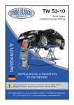
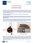
QJYJ30-CB Scissor Vehicle Lift
Operation Manual
Instructions are part of the product, please place where you
can always find for easy reference. Read the instructions
carefully before the start of installation, operation and
Tongrun lift and its distributors are not liable for any
accidents caused by misuse, abuse, alterations on parts,
which not authorized by them.
INDEX
1. Important safety instructions…………………………………...………..1-2
1.1 Important notices
1.2 Qualified personnel
1.3 Danger notices
1.4 Warning signs
2. Overview of the lift…………………………..…………………………..3-4
2.1 General descriptions
2.2 Technical data
2.3 Construction of the lift
3. Installation instructions……………………..……………………………4-9
3.1 Preparations before installation
3.1.1 Tools and equipments needed
3.1.2 List for parts checking
3.1.3 Ground conditions
3.2 Precautions for installation
3.3 Installation
3.4 Items to be checked after installation
4. Operation instructions……………….…………………………………10-11
4.1 Precautions
4.2 Descriptions of control box
4.3 Operating instructions
5. Trouble shooting……………………………….……………………….....12
6. Maintenance……………………………………………………………13-14
7. Annex……………………..…………………………………………....15-24
Annex 1
Annex 2
Annex 3
Annex 4
Annex 5
Annex 6
Annex 7
Packing list of the whole lift
Overall diagram
Hydraulic working system
Wiring diagram
Diagram for air supply connection
Spare parts list
Separated drawings for the lift
IMPORTANT SAFETY INSTRUCTIONS
1.1 Important notices
·The lift is specially designed for lifting vehicles that weighs within its outmost lifting capacity. Users are
not allowed to use it for any other purposes. Otherwise, Tongrun lift, as well as our sales agency, will not
bear any responsibility for accidents or damages of the lift.
·Tongrun lift provide one-year's quality warranty for the whole machine. Personal or property damage
directly or indirectly caused by improper installation or any abuse, the company does not undertake any
responsibility.
·Please read this manual carefully before installation and operation, to avoid any property damage, or life
injury caused by improper operation.
·Without our professional advice, users are not permitted to make any modification to the control unit or
whatever mechanical unit.
1.2 Qualified personnel
1.2.1 Only these qualified staff, who have been properly trained, can operate the lift.
1.2.2 Electrical connection must be done by a competent electrician.
1.2.3 People who are not concerned are not allowed in the lifting area.
1.3 Danger notices
1.3.1 Do not install the lift on any asphalt surface.
1.3.2 Read and understand all safety warnings before operating the lift.
1.3.3 Do not leave the controls while the lift is still in motion.
1.3.4 Keep hands and feet away from any moving parts. Keep feet clear of the lift when lowering.
1.3.5 Only these properly trained personnel can operate the lift.
1.3.6 Do not wear unfit clothes such as large clothes with flounces, tires, etc, which could be caught
by moving parts of the lift.
1.3.7 To prevent evitable incidents, surrounding areas of the lift must be tidy and with nothing
unconcerned.
1.3.8 The lift is simply designed to lift the entire body of vehicles, with its maximum weight within
the lifting capacity.
1.3.9 Always insure the safety latches are engaged before any attempt to work near or under the vehicle.
Never remove safety related components from the lift. Do not use if safety related components are
damaged or missing.
1.3.10 Do not rock the vehicle while on the lift or remove any heavy component from vehicle that may
cause excessive weight shift.
1.3.11 Check at any time the parts of the lift to ensure the agility of moving parts and the performance
of synchronization. Ensure regular maintenance and if anything abnormal occurs, stop using the lift
immediately and contact our dealers for help.
1.3.12 Lower the lift to its lowest position and do remember to cut off the power source when
service finishes.
1.3.13 Do not modify any parts of the lift without manufacturer’s advice.
1.3.14 If the lift is going to be left unused for a long time, users are required to:
a. Disconnect the power source;
b. Lubricate the moving parts with hydraulic oil;
c. Empty the oil tank.
Warning: lifting machine is of high risk products. Improper installation and
operation, or modification on the parts without authorization, are likely to cause
damage to the operator, even resulting in death. Read the instructions carefully
and strictly operate the lift according to the requirements.
1
1.4 Warning signs
2
OVERVIEW OF THE LIFT
2.1 General descriptions
QJYJ30—CB is four-cylinder scissors lift, designed for the surface installation, easy to install. Apply
to all kinds of small and medium-sized vehicles weighted under 3.0 t, it serves for auto repair and
maintenance; it also can be used in the production line, transition of goods on automatic line with
different height, material handing online and offline.
Its four-cylinder structure makes the lowest 110mm clearance from ground come true. Its platform
extension deign may not only be used as a ramp, but also can serve as an extended part of the platform
for much longer vehicles. Besides, designs like, 24V working voltage of control box, alarming buzzer,
pneumatic safety lock, etc have fully considered your personal security.
Safety structure:
2.2 Technical data
Model
Lifting Lifting Fall
capacity time time
QJYJ30-CB 3000KG
<55s
Lifting
height
Total
weight
<40s 1850mm 895KG
2.3 Construction of the lift
3
Table
space(adjustable)
Recommended
Power supply
800mm
220V,Single-phase
380V,three-phase
INSTALLATION INSTRUCTIONS
3.1 Preparations before installation
3.1.1 Tools and equipments
·Electrical drill
·Open wrenches
·Screw drivers
·Hammer
3.1.2 List
needed
for parts checking --- Annex 1(Packing list)
Open the package, refer to the attachment 1 (packing list), check all parts, if any parts
missing happen, please contact the dealer or manufacturer immediately. In this case, you
should not continue installation. Otherwise Tongrun lift and distributors are not liable.
3.1.3 Ground
conditions
The lift should be fixed on a smooth and solid concrete ground with its strength more than
3000psi, tolerance of flatness less than 5mm and minimum thickness of 200mm. In addition,
newly built concrete ground must undergo more than 28days’ cure and reinforcement.
4
3.2 Precautions for installation
3.2.1 Joints of oil hose must be firmly connected in order to avoid leakage.
3.2.2 All bolts should be firmly screwed up.
3.2.3 Do not place any vehicle on the lift in the case of trial running.
3.3 Installation
Step1: Dismantle all of the outer packing, to move the platform, put them in previous concrete
ground, keep space of 800mm between two platforms horizontally, as shown in the figure, in the
process of dismounting, please be careful not to make oil tube bent, so as to avoid distortion.
5
Step2: Connect oil hoses (This step is extremely important, so do refer to the
diagram for of oil hose connection and understand the following instructions
before proceeding)
A、make sure there is nothing obstructed or dirty left in the hose.
B、Installers have to distinguish where the chief oil hose to be connected by referring to the below
pictures and have the chief hose connected.
C、See the left picture followed by two branches of the chief oil hose are going to be
respectively connected to the tie-ins for chief oil hose reserved on the hydraulic block and the
other scissor. Similarly, branches of the other two leveling hoses are going to be connected to
the tie-ins reserved for leveling hoses.
D、Check if all connections are tightened.
Chief oil hose is in the middle,
Deputy oil hose is on both sides.
6
Step3: Connect the electrical and pneumatic system.
Connect the external power supply plugs according to electrical schematic diagram, as Annex 4
shown and then connect an external high pressure gas source (pneumatic 0.6~0.8kg/cm²) to the
oil-water separator inlet of pumping station, and then connect oil pipe of safety lock to the gas
port of pneumatic solenoid valve of pumping station.
Step4: Fill with hydraulic oil.
Pour into the oil tank with 16 liters of anti-grinding oil. Level of the oil shall be 10mm
to 40mm away from the top of the tank. (Users can measure it by the feeler attached on
the lid).
Step5: Leveling
Before leveling, make sure the oil hoses are correctly connected. Otherwise, oil cylinders may
not work synchronously or could be damaged. In addition, operators need to know clear which
leveling valve controls which platform. This could be judged by the way that the oil hose was
connected or by trial raising or lowering.
Manual leveling
Open one of the leveling valves and press the UP button to supplement oil to the oil hose
connected. Close the valve to stop adding oil. In normal working condition, both leveling
valves are closed. If both valves are open, two platforms of the lift can still rise but will not
move upwards synchronously.
7
A1.Open both leveling valves and press the UP button to have both platforms raised to the
highest positions. Repeat this step for two or three times. (Take care that this step could be
time consuming, because there’s air in the cylinders and no load on the platforms.)
A2.Close both leveling valves as fig B. Press the UP button to see if both platforms rise
synchronously. (Normally, till now the platforms may not rise synchronously.)
A3.If not work synchronously, one platform may rise faster than the other. Users should
first judge which leveling valve controls which platform and then open the valve that
controls the slower-rising platform to supplement oil into its oil hose. Press the UP button to
make both platforms rise to the same height. (The other valve here must be closed.)
A4.Close both leveling valves. Press DOWN button to have both platforms lowered
to the lowest position.
A5.If they do not lower synchronously, open the valve that controls the slower-lowering
platform and press DWON button to have them lowered to the lowest position and then
close the leveling valve.
A6.After both leveling valves having been closed, press the UP button to check if both
platforms rise synchronously.
A7.Repeat doing A5 and A6 until synchronization achieved.
Step6: Fix expansion bolts.
1.Drill anchor holes for expansion bolts on the ground with an electrical drill. Make sure to
drill vertically.
2.Remove thoroughly the debris and dust in holes and ascertain that the posts stay right
upon the circle previously marked by chalk.
3.Hammer in and secure expansion bolts.
8
Step7: Install oil hose protection covers.
Put two guard plates according to below diagram, drilling holes for expansion tube
using electrical drill in the Location of the prepared for guard plate, sweep the dust,
put expansion tube under the guard plate, then tighten the screw from top of guard
plate.
3.4 After the installation, check the following items:
a. platforms be leveled
b. oil tubing be connected properly
c. electrical parts be connected correctly
d. no oil leaking in the valve of the pump station
9
OPERATION INSTRUCTIONS
4.1 Precautions
4.1.1 Check all the joints of oil hose. Only when there is no leakage, the lift can start work.
4.1.2 The lift, if its safety device malfunctions, shall not be used.
4.1.3 The machine shall not lift or lower an automobile if its center of gravity is not positioned
midway of the rising platforms.
4.1.4 Operators and other personnel concerned should stand in a safety area during lifting and
lowering process.
4.1.5 When platforms being raised to the desired height, switch off the power at once to prevent
any wrong operation done by unconcerned people.
4.1.6 Make sure the safety locks of the lift are engaged before start working under the vehicle
and no people under the vehicle during lifting and lowering process.
4.2 Descriptions of control box
10
4.3 Operation instructions
Raise the lift:
1.Make sure that you have read and understood the operation manual before operation.
2.Drive and park the vehicle midway between two platforms.
3.Place the four rubber pads under the prop-points of the vehicle and ensure car’s gravity have
fallen on the rubber pads.
4.Press the UP button on the control box until rubber pads have touched the prop-points of vehicle
5.Keep on pressing the UP button to lift the vehicle a bit higher from the ground and check
again if the vehicle is in a safe position.
6.Having raised the vehicle to the required height, press the “lock” button to make the mechanical
safety lock be engaged and then press the “emergency stop” and check again the stability of the
vehicle before performing maintenance or repair work.
Lower the lift:
1.Open the emergency stop switch.
2.Press and hold DOWN button, the platform will raise a certain height, in order to open the
insurance part, then the platform begin to descend.
3.The machine is equipped with safety warning device, it’s normal to hear alarm voice throughout
the descending process.
4.The falling process goes from fast speed at the beginning to slow speed later, when the height off
the ground comes nearly 400mm, the speed of decline becomes obviously slow. The lift is designed
and aims to enhance security
5.Drive away the car when platform be lowed to the minimum height.
Note:
1. It is normal to find that two platforms may work with slight
non-Synchronization after a period of using. Serious consequences will
happen if you do not level it in time, and it may cause damage on operator
and even death. So it is very important that you should always pay
attention to the Synchronization of lift.
2. You should avoid any over travel of Platform when it rises to the
highest, thereby reducing the life of cylinder, and increases the risk.
3. In the course of using, you should cultivate the habit of keep an eye
on relationship between relative position of axis parts, pay attention to any
Axial displacement of them, Once you have found this situation, please do
not hesitate to contact the manufacturer, Get professional help and service,
reduce unnecessary losses.
11
TROUBLE SHOOTING
ATTENTION: If the trouble could not be fixed by yourself, please do not hesitate to
contact us for help .We will offer our service at the earliest time we can. By the way,
your troubles will be judged and solved much faster if you could provide us more
details or pictures of the trouble.
TROUBLES
Motor does not run
and will not raise
Motor runs
but will not raise
Raising too slow
Platforms go down slowly
after being raised
Lowering too slow
Safety lock cannot be opened
CAUSE
SOLUTION
The motor is burnt
Replace it
The wire connection is loose
Check and make a good connection
Fuse is burned
Replace it
The motor run reversely
Check the wire connection
Oil level is too low
Add oil
The relief valve is damaged
Fix or replace it
The oil hose became loose
or dropped off
Tighten it
Oil level is too low
Add oil
The overflow valve is not
adjusted to the right position
Adjust it
The lift is overloaded
Check the weight of the vehicle
The oil filter is jammed
Clean or replace it
The seal of the cylinder is abraded
Replace the seal
The oil hose leaks
Check or replace it
Electrical unloading valve leaks
Clean or replace it
The single valve leaks
Clean or replace it
The oil cylinder is not tightened
Replace the seal
The hydraulic oil is dirty
Change the oil
The oil hose jammed
Replace it
Lowering restrictive valve is
Turn lowering restrictive valve up
turned too low
The air pressure regulating valve is
Adjust air pressure to 5kg/cm2
closed or too low
The Solenoid air valve is damaged
12
Replace it
MAINTENANCE
Easy and low cost routine maintenance can ensure the lift work normally and
safely. You may choose the frequency of routine maintenance by consulting
your lift’s working conditions and time.
The following parts need to be lubricated:
1.The slide panel
2.Middle axis
3.Fixed axis of Slide bar
4.Oil cylinder connecting shaft
5.Oil cylinder fixed axis
6.Fixed axis of firm rod
7.Block 1
8.Block 2
6.1 Daily checking items before operation
The user must perform daily check. Daily check of safety system is very
important – the discovery of device failure before action could save your
time and prevent you from great loss, injury or casualty.
·This machine should be constantly wiped and clean up ,and keep it clean. Before wiping,
cut the power, ensure security.
·Check whether oil hose well connected. No leakage is allowed.
·Check the electric connections. Make sure all connections are in good condition.
·Check if safety teeth and safety block matched well or not.
6.2 Weekly checking items
·Check the flexibility of moving parts, and lubricate all pivot pins.
·Check whether the expansion bolts well anchored.
·Check the working conditions of safety parts.
·Check the amount of oil left in the oil tank. Oil is enough if the carriage can be raised to
highest position. Otherwise, oil is insufficient.
13
6.3 Monthly checking items
·Check whether the expansion bolts well anchored.
·Check the tightness of the hydraulic system and screw firm the joints if it leaks.
·Check the lubrication and abrasion circumstance of moving parts.
6.4 Yearly checking items
·Check the lubrication and abrasion circumstance of moving parts.
·Empty the oil tank and check the quality of hydraulic oil.
·Wash and clean the oil filter.
6.5 Every three years or more than 5,000 routine maintenance items
·Replace the pin, bearings, tubing connector components.
ATTENTION: Strict maintenance of the machine according to the above
requirements, the machine will keep work normally, and prevent accidents
occurring to a large extent at the same time.
14
Annex
Annex 1, Packing List of the whole lift
1#
2#
3#
platform 1
platform 2
packaging wooden box of electric parts (including the following parts)
S/N
Name
1
The control box
2
Expansion bolt
Plastic expansion
tubes
Semi-sphere head
tapping screws
3
4
5
Connecting tubing
6
7
8
9
Chief oil hose
Deputy oil hose
Tubing cover
Thin rubber mat
10
File
11
Air hose
Spec
Qty
QJYJ30-CB.8
1
M16*140
8
M8*30
8
ST5*30
8
note
Motor, hydraulic oil tank, pneumatic
electromagnetic reversing valve,
oil-water separator
Packed in one
3
QJYJ30-CB.6-07
QJYJ30-CB.6-08
QJYJ30-CB.6-21
QJY4040.8-07
1
2
2
4
1
PU0604
1
Annex2, Overall diagram
15
#1tube length 1480mm, #2tube length
1400mm, #3tube length 1325mm
Length 3070mm
Length 3380mm
Including user’s manual and certificate of
approval
Length 1400mm
Annex 3, Hydraulic working system
16
Annex4, Wiring diagram
Single-phase(220V)
17
Three-phase (380V)
18
Annex5, Diagram for air supply connection
Annex 7, Spare parts list
S/N
Name
Spec
Unit
Qty/
set
1
Power
switch
YMW26-20/2GS
Pcs
1
2
Button
LA135-11/20A3(W)
Pcs
1
3
Button
LA135-20/20A3(W)
Pcs
2
19
Pictures
Same outlook as
item2
S/N
Name
Spec
Unit Qty/set
4
Alarm lamp
AD115-22/21-DM AC/DC 24V
(R)
Pcs
1
5
Power indicator
AD115-22/1-A7 AC/DC 24V
(G)
Pcs
1
6
transformer
BK40 40VA AC380V-AC24V
BK40 40VA AC220V-AC24V
Pcs
1
7
AC contactor
TRC2-12/AC 24V-10
Pcs
1
8
Circuit breaker
TRH1-63 3P/C16A
Pcs
1
9
Circuit breaker
TRH1-63 1P/C3A
Pcs
1
10
Circuit breaker
TRH1-63 1P/C1A
Pcs
1
11
Emergency stop
LA135-01MXS/20B9 (R)
button
Pcs
1
20
Pictures
Same outlook as
item9
S/N
Name
Spec
Unit
Qty/s
et
12
Bridge
rectifier
QL-3510
Pcs
1
13
Capacitance
4700uF 50V
Pcs
1
14
Relay
MY2N-J 24VDC
Pcs
1
15
Relay seat
Pcs
1
16
Pneumatic
valve
Pcs
1
3V210-08
21
Pictures
Annex 7, Separated drawings for the lift
22
Product exploded diagram list
S/N
1
2
3
4
5
6
7
8
9
10
11
12
13
14
15
16
17
18
19
20
21
22
23
24
25
26
27
28
29
30
31
32
33
34
35
36
37
38
39
40
Drawing no.
QJYJ30-CB.1
QJYJ30-CB.2.2
GB894.1
SF-2
QJYJ30-CB-03
QJYJ30-CB.2-03
GB70.2
QJYJ30-CB.2-06
SF-2
QJYJ30-CB.2-02
GB1155
QJYJ30-CB.2.1
SF-2
QJYJ30-CB.2-01
QJYJ30-CB-01
QJYJ30-CB.2-04
QJYJ30-CB.2.3
QJYJ30-CB.2.2
QJYJ30-CB.3.2
QJYJ30-CB.3.3
QJYJ30-CB.3.1
GB894.1
QJYJ30-CB.3-02
QJYJ30-CB.3-01
QJYJ30-CB.2-05
GB77
QJYJ30-CB-02
QJYJ30-CB-06
QJYJ30-CB-05
GB894.1
SF-2
QJYJ30-CB-04
QJYJ30-CB.5-03
QJYJ30-CB.5-01
QJYJ30-CB.5-02
QJYJ30-CB.6-11
QJYJ30-CB.6-12
QJYJ30-CB.6-13
SF-2
QJYJ30-CB.6.1
Name
The base components
bottom rod
Shaft Retaining rings 25
bushing 2525
The base fixed axis
Nylon slider
Hexagon flat head screws M6X10
middle axial fixed cushion
bushing 3035
Middle axis
Oil cup Φ6
Bottom slider
bushing 4020
Slider fixed axis
Platform fixed axis
Nylon pulley
Upper slider
Bottom rod
Support bar
Extension plate
Platform Panel
Shaft Retaining rings 12
Extension plate fixed axis
Extension plate roller
Rod fixed axis
Hexagon flat - End Set screws M8X10
Oil cylinder fixed axis
Pulley 1
Oil cylinder connecting shaft
Shaft Retaining rings 30
bushing 3025
Connection plate fixed axis
Pulley 2
Connection plate connecting shaft
Connection plate collar
main oil cylinder
Secondary oil cylinder
Cover plate
bushing 2520
Safety bar parts
23
Qty
2
2
12
12
4
8
22
12
8
8
12
2
16
4
4
4
2
2
4
4
2
16
8
8
2
26
4
4
2
4
8
2
4
2
2
2
2
2
8
2
S/N
41
42
43
44
45
46
47
48
49
50
51
Drawing no.
QJYJ30-CB.6.2
QJYJ30-CB.6-20
QJYJ30-CB.6.3
QJYJ30-CB.7.1
QJYJ30-CB.7-01
QJYJ30-CB.6-16
QJY245DS.8-06
QJYJ30-CB.6-06
QJYJ30-CB.6-05
QJYJ30-CB.6-04
QJY4040-14
Name
Safety lock tongue parts
The lock tongue fixed shaft
Oil cylinder connecting plate
Cylinder block parts
Air cylinder
oil tubing connector
Three way pipe joint
Oil cylinder tubing 3
Oil cylinder tubing 2
Oil cylinder tubing 1
Expansion bolt M16X140
Qty
2
2
2
2
2
8
3
2
2
2
8
The company is committed to constantly improving the product quality,
update technology specifications, they are subject to change without
notice.
24