1
NISSAN NORTH AMERICA, INC.
-
Copyright @
i
,a
SERVICE BULLETIN
1
Classification:
~
!Reference:
NTBOI-073a
EL01-022
Date:
I November 9,2001
This bulletin has been revised. The Applied Vehicle(s) were updated.
Please discard paper copies of NTB01-073.
APPLIED VEHICLE(S): 2002 Altima (L31)
2002 Maxima (A33)
SERVICE INFORMATION
If the radio of an applied vehicle exhibits the following symptom:
0
Static noise heard from the speakers that "follows" engine speed on certain FM radio
stations,
The cause may be the ignition coil resistors. A new resistor assembly (located inside the
ignition coil tube) is available to repair the described symptom, if it should occur.
SERVICE PROCEDURE
1. Start the engine and allow it to idle.
2. Turn radio on and search for several FM stations until a steady "ticking" or "popping"
noise is heard through the speakers.
Notes:
Weaker radio stations may make the static noise easier to detect, if it exists.
Increasing the treble and decreasing the bass settings may also make the "ticking"
noise easier to detect, if it exists.
3. If the incident is duplicated, accelerate the engine and note if the frequency of the
"ticking" or "popping" noise increases with engine speed.
4. If the noise does not follow the engine speed, the incident is not caused by the ignition
coils. Consult the appropriate section of the Service Manual to diagnolse and repair the
incident.
5 . If the noise follows the engine speed, remove all ignition coils from the engine. Refer to
the 2002 vehicle's Service Manual for removal procedure of the ignition coils.
Altima with 4 cylinder engine-page EM-26
Altima with 6 cylinder engine-page EM-I27
Maxima-MA-I7 (changing spark plugs), steps 1 to 3 only.
1/3
Notes for Maxima and Altima with 6 cylinder engine:
It is only necessary to separate the intake collector from the intake manifold to
remove the ignition coil. Do not remove the throttle body from the intake collector
It is not necessary to drain the coolant.
6. Replace the resistor assembly in all ignition coil tubes as follows:
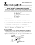
A. Pull the rubber boot away from the ignition coil. Then, twist and pull the ignition coil
tube from the ignition coil to separate them (see Figure 1, 6 cylinder shown, 4
cy1inder simiI ar) .
e
rRubber boot
-
Ignition coil
TP010644
Figure 1
B. Remove the old resistor assembly parts from the ignition coil tube and discard.
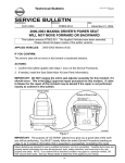
Insert the new resistor assembly into the ignition coil tube in the orientation shown in
Figure 2 below (6 cylinder shown, 4__cylinder similar).
,-Ignition coil
C. Assemble the ignition coil tube to the ignition coil.
Rotate the tube while pressing onto the coil.
0 A "pop" sound will be heard when the rubber boot is seated correctly to the
ignition coil.
Ensure there are no gaps and bulges between the coil body and the rubber boot
7. Install the repaired ignition coils with the new resistor assembly to the engine. Refer to
the 2002 vehcile's Service Manual for installation procedure of ignition coils.
Altima with 4 cylinder engine-page EM-26
Altima with 6 cylinder engine-page EM-I27
Maxima-MA-I7 (changing spark plugs), steps 1 to 3 only.
8. Check to ensure the incident has been resolved.
PARTS INFORMATION PART #
22468-8J125
14032-8J105
22468-6N225
DESCRIPTION
Spring Kit (6 cylinder)
Gasket-Intake Collector(6 cylinder)
Spring Kit (4 cylinder)
QUANTITY
CLAlMS INFORMATION
Submit a Primary Failed Part (PP) line claim using the following claims coding:
DESCRIPTION
R&R All 4 or 6 Coils & RPL
Resistor Assy's (includes R&R
Collector, if required)
PFP
(1)
OPCODE
GX07AA
SYM
HB
DIA