1
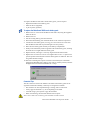
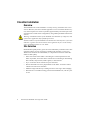
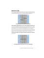
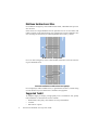
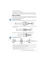
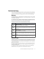
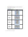
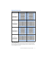
~etroCount
®
The Traffic Data Specialists
Roadside Unit Operator Guide
MetroCount 5600 Series
January 2002
®
©MetroCount
Contents
MetroCount 5600 Roadside Unit......................................................................1
Overview.....................................................................................................1
Roadside Unit Operating States..................................................................1
Roadside Unit Status LEDs ..............................................................................2
Roadside Unit Communications.......................................................................2
Roadside Unit Memory Capacity .....................................................................3
Roadside Unit Battery Life...............................................................................3
Checking the Battery Level ........................................................................4
Main Battery Pack Replacement ......................................................................4
Classifier Installation........................................................................................6
Overview.....................................................................................................6
Site Selection ..............................................................................................6
Bidirectional Sites.......................................................................................7
Multilane Unidirectional Sites ....................................................................8
Suggested Toolkit .......................................................................................8
Sensor Installation.......................................................................................9
Roadside Unit Setup .......................................................................................11
Debounce ..................................................................................................11
Direction Codes ........................................................................................11
Lane Numbering .......................................................................................13
Count Installation ...........................................................................................14
Factory Setup..................................................................................................15
MetroCount Traffic Survey Equipment Warranty .........................................16
ii
MetroCount Roadside Unit Operator Guide
MetroCount 5600 Roadside Unit
Overview
This guide is an introduction to the operation and installation of the MetroCount
5600 Series Roadside Unit. For detailed software instructions, refer to your
MetroCount Traffic Executive User Manual.
The MetroCount 5600 Series Roadside Unit is a dual air-sensor data logging unit.
The MetroCount 5600 is powered by a user-replaceable alkaline battery pack,
giving up to 290 days continuous data collection.
The PVC Main System Unit is totally weatherproof. Communication with the
Roadside Unit is performed via the sealed circular connector, using a standard
RS-232 PC communications port, and the software supplied. Mechanical protection is provided by the stainless-steel Road Case.
The MetroCount 5600’s Status LEDs provide feedback about the unit’s current
state, and functionality of the air sensors.
Roadside Unit Operating States
The MetroCount 5600 has three operating states.
Idle
Deferred
setup
Active
Deferred
Immediate
setup
Start time
reached
Unload &
stop
Active
Logging
Unload
MetroCount 5600 Operating States
The Idle state is the Roadside Unit’s standby mode. In this state, the Roadside
Unit does not log any data, and simply retains existing data.
The Roadside Unit is set to its Active Logging state by performing a Setup operation. In this state, the Roadside Unit logs axle hits on it’s respective air sensors,
and performs a number of maintenance tasks. The logging start time can be deferred for up to 10 days. In its deferred state, the Roadside Unit will be active, but
will not log sensor hits.
The Roadside Unit does not require a stop time or logging duration. It simply continues to log axle events until an Unload operation using the Unload and Stop
mode is performed, or its memory capacity is filled.
The MetroCount 5600 has an additional power saving feature where the unit will
switch to its Idle state if no sensor hit is detected for a week.
MetroCount Roadside Unit Operator Guide
1
Roadside Unit Status LEDs
The MetroCount 5600 has three Status LEDs, located near
the air sensors. The A and B Status LEDs operate in
either of the Roadside Unit’s active states.
When an air sensor is triggered by an
air pulse, the respective Status LED
will flash. This allows you to check
sensor installation, and easily identify problems, such as blockages.
The Heart Status LED is used to indicate the Roadside Unit’s current state,
as described in the table below.
♥ LED
Status
Flashing:
Every 8 seconds
Idle State - the Roadside Unit should be in this state when
not in use.
Flashing:
Every 2 seconds
Active Deferred State - the Roadside Unit is active, waiting
for the specified start time.
Flashing:
Every second
Active Logging State - the Roadside Unit is active, and
logging sensor hits.
On continuously
Communications Active - the Roadside Unit is waiting for
commands.
Off continuously
Data transfer in progress - the Roadside Unit is unloading
data, or in Traffic View mode.
Roadside Unit Communications
The MetroCount 5600 Roadside Unit is controlled via a standard RS-232 serial
communication port, using MCSurvey for desktop and laptop PCs, or MCSetLite
for Pocket PCs.
Your PC is connected to the MetroCount 5600’s circular connector, located between the unit’s two air sensors, via the supplied communications cable. Note that
the connector is keyed to facilitate correct alignment - simply push and rotate the
connector until it goes in. Note also that you do not need to screw on the cable to
make contact.
The ideal scenario is to invest in a mobile PC for use in the field. This allows units
to be moved from site to site, without returning them to your office. If you do not
have a laptop PC, setup the units in your office, with a deferred start time, and use
the Status LEDs to ensure correct sensor installation on site.
2
MetroCount Roadside Unit Operator Guide
Roadside Unit Memory Capacity
Traffic volume at your site dictates how long it will take to fill your Roadside
Unit’s memory. Higher flow rates result in shorter logging periods. Use the table
below as a guide to how long a Roadside Unit will last at a given site, based on
an approximation of daily volumes and axle hits per vehicle.
Roadside Unit
Memory Capacity
Total Axle Events
(maximum)
512K
240,000
1M
490,000
2M
990,000
Remember that once a Roadside Unit fills to capacity, it will shut down. If you
wish to survey a site for longer than the capacity will allow, it is a very simple
process to unload the collected data and setup the Roadside Unit again. The analysis software supports data file fragments from a single survey.
Roadside Unit Battery Life
The MetroCount 5600 uses a non-rechargeable, alkaline battery pack. In its idle,
low power state, the MetroCount 5600 draws a negligible current, giving it a shelf
life in excess of five years, with only minor capacity degradation.
The diagram below shows the battery pack discharge characteristic, when the
MetroCount 5600 is in its active state, for battery packs supplied by MetroCount.
MetroCount 5600 battery discharge characteristic when logging
MetroCount Roadside Unit Operator Guide
3
An important point to note is that the battery discharge curve is not linear. Initially, there is quite a drop in voltage before levelling out. With continuous use, the
MetroCount 5600 will last for about 290 days before the battery pack requires replacing.
Checking the Battery Level
The Roadside Unit battery levels are displayed as part of the Roadside Unit status
in either MCSurvey or MCSetLite.
Checking the battery level of the MetroCount 5600
The approximation of active life remaining is derived from the current main battery voltage, and the discharge curve. Warnings will be issued when checking the
Roadside Unit status well in advance of when the battery pack requires replacing.
The MetroCount 5600 also contains a RAM backup cell to retain memory contents while the main battery is changed. This is automatically charged from the
main battery and will usually stay in the green region.
Main Battery Pack Replacement
Replacing the MetroCount 5600’s main battery pack is a very simple procedure.
It is highly recommended that you always use MetroCount supplied replacement
battery packs. These will ensure the highest reliability, and the longest logging capacity. Common spring-based battery packs are unreliable and may cause logging
to be interrupted.
The MetroCount 5600’s main battery will not fail suddenly, so there is plenty of
lead time to organise replacement. Even at zero days remaining, you will still be
able to communicate with the Roadside Unit to unload data.
Whilst the MetroCount 5600 has a memory backup battery, it is recommended
that you unload any required data in a Roadside Unit’s memory before changing
the main battery pack.
4
MetroCount Roadside Unit Operator Guide
To replace the MetroCount 5600’s main battery pack, you will require:
•
Replacement MetroCount battery pack.
•
4mm hex driver (supplied).
•
A pair of pliers (optional).
To replace the MetroCount 5600’s main battery pack
1. Remove the six screws from the MetroCount 5600’s lid, using the supplied
4mm hex driver.
2. Remove the lid.
3. Lift the existing battery pack from the base.
4. Disconnect both battery pack terminals. Refer to the connector tips below.
5. Connect the new battery pack, ensuring you colour-match the leads. Note
that the MetroCount 5600 is protected against reverse polarity.
6. Place the new battery pack centrally in the battery compartment.
7. Neatly route each battery lead on opposite sides of the battery pack, ensuring
the leads are not caught under the battery pack.
8. Replace the lid, ensuring it is correctly aligned with the Status LEDs.
9. Replace the six lid screws. Do not over-tighten these screws - a quarter turn
past the point that the lid mates with the rubber gasket is sufficient. The rubber gasket should not bulge.
10. Note that a warning that a power event has occurred may be issued after
changing the Roadside Unit’s battery pack. This is perfectly normal, and will
disappear the next time the Roadside Unit is setup.
Connector Tips
The tab connectors used on the MetroCount 5600’s main battery pack are designed for maximum reliability. Some tips on using these terminals:
•
The terminals are best separated using a rocking, side-to-side action.
•
Always grip the terminals - try to avoid pulling on the leads.
•
Consider using a pair of pliers to grip the terminals.
•
When reconnecting, the terminals should click into place.
Note: Never allow the two battery pack terminals to make contact!
MetroCount Roadside Unit Operator Guide
5
Classifier Installation
Overview
The Roadside Unit can be installed in a variety of ways, with either one or two
sensors. However, the most common approach is to use a Classifier Sensor Layout, which requires two sensors in parallel, approximately one metre apart. This
section focuses on this sensor configuration, using rubber pneumatic tubes for the
sensors.
Warning: Installation and use of the Roadside Unit should be by competent, and,
if and where applicable, duly qualified personnel.
Installers and users of the Roadside Unit should ensure that they have referred to
and have regard to all relevant statutes and regulations in force in the locality
where installation and use is to be made.
Site Selection
Resultant data quality from a given site can be affected by a number of site characteristics. Below is a list of points to consider when selecting a survey site.
Whilst some situations are unavoidable, it is important to be aware of the sideeffects to data quality.
6
•
Select sites where most traffic is travelling at a constant speed across the
tubes. If possible, avoid sites where vehicles are accelerating or decelerating
due to bends, steep inclines, traffic signals, or intersections.
•
Try to avoid sites where vehicles stop over the tubes.
•
Ensure that traffic will cross perpendicular to the tubes. Avoid sites where
vehicles will turn across the tubes.
•
Minimise single tube hits by avoiding excessive swerving or lane changing.
•
Ensure there is a suitable securing point for the Roadside Unit, such as a post
or tree.
MetroCount Roadside Unit Operator Guide
Bidirectional Sites
When surveying a bidirectional traffic flow, the preferred installation method is
to use one Roadside Unit per lane. This approach will ensure the best achievable
accuracy for a given site, in terms of volume, classification and speed.
Preferred method for surveying bidirectional sites
When installing one Roadside Unit across two lanes of bidirectional traffic, careful consideration must be paid to the level of resultant degradation of data quality.
As with any classification system based on two parallel sensors, there is a problem when two vehicles traverse the sensors simultaneously. The sequence of axle
hits produced by such an event makes it difficult to discern actual vehicles.
There is no rule-of-thumb for when a single Roadside Unit can be used for bidirectional traffic. If the occurrences of two vehicles crossing the tubes simultaneously is very low, then data quality will be very good. As the number of
simultaneous crossing events increase, data quality will decrease. It is a matter of
assessing the convenience of a single unit, against the acceptable data quality for
any given site.
Surveying bidirectional traffic may result in loss of data quality
MetroCount Roadside Unit Operator Guide
7
Multilane Unidirectional Sites
For multilane carriageways with unidirectional traffic, a Roadside Unit per lane
must be used.
If the sensors of a single Roadside Unit are placed across two or more lanes with
traffic travelling in the same direction, the resultant axle events of multiple vehicles travelling in echelon may be indistinguishable from a heavy vehicle.
Do NOT use this configuration!
For a two lane carriageway with a central median, both lanes can be accessed using two Roadside Units.
Preferred installation for unidirectional carriageways
For carriageways with no median access, or greater than two lanes, consider using
a Count Sensor Layout to obtain basic volumetric and gap data.
Suggested Toolkit
An adequate supply of simple, yet high quality tools is essential for safe, speedy
tube installation. A minimum set of tools include:
8
•
Small mallet, heavy duty claw hammer or heavy ball hammer.
•
Crowbar.
•
Side cutters or pliers.
MetroCount Roadside Unit Operator Guide
•
Chalk or lumber crayon.
•
Tape measure, or one metre stick.
•
High quality safety equipment including all safety equipment required by
any relevant statutes or regulations in force and personal safety equipment.
Sensor Installation
The following section discusses the installation of a Roadside Unit using a Classifier Sensor Layout. The tips and techniques discussed here can be carried over
to Count Sensor Layout installations.
To attach a Figure-8 Cleat
1. Place one end of the pneumatic tube over the large loop of a Figure-8 Cleat.
2. Twist the Figure-8 Cleat to form a second loop, and slide over the end of the
pneumatic tube.
3. Bunch the two loops together, and pull the tube through as required.
To install pneumatic tubes
1. Prepare two tubes of equal length, and sufficiently long to cover the required
lanes, and reach the Roadside Unit securing point.
2. Using a tape measure, or one metre stick, mark the one metre tube spacing on
the road with a lumber crayon or chalk.
3. Attach Figure-8 Cleats to one end of each tube, using two per tube.
MetroCount Roadside Unit Operator Guide
9
4. Seal the same end of each tube with two knots, adjacent to the cleats.
5. Secure both tubes to the road, using a road nail through the eyelet of each
cleat.
6. Attach Figure-8 cleats to the kerb side of each tube, using two per tube, and
secure to the road using road nails. Ensure that the tubes are parallel to each
other, and perpendicular to the direction of vehicle travel.
7. Double-check that the tube spacing is one metre.
8. Stretch each tube 10% to 15% to minimise lateral movement. Use a cable tie
around the kerb side cleats if necessary to prevent slippage.
9. Ensure that the tube length from the kerb to the Roadside Unit air sensors is
exactly the same. A difference in length will result in incorrect speeds and
wheelbases.
10. Attach Centre-Line Cleats as required using two road nails per cleat. This
will minimise lateral movement over long distances. Using one in the centre
of each lane, in addition to between two lanes will maximise data quality.
11. Remove the inner tray from the stainless steel case and feed both tubes up
through the handle.
12. Place the PVC main system unit next to the tray and attach each tube to the
appropriate air sensor. Remember to use the convention of the A tube being
the first hit by a vehicle travelling in the lane closest to the Roadside Unit.
Use the Roadside Unit’s Status LEDs, or the Traffic View on a mobile PC, to
verify the correct tube connections.
13. Place the PVC main system unit into the tray, and push each tube into the
tray’s respective locking cut-outs, as shown in the diagram below.
14. Slide the tray into the outer case, and secure the Roadside Unit using a padlock through one of the holes in the handle.
10
MetroCount Roadside Unit Operator Guide
Roadside Unit Setup
The procedure for Roadside Unit setup is covered in your MetroCount Traffic Executive User Manual or MCSetLite User Guide. The following sections provide
a reference for the Debounce setting, Direction Codes, and Lane Numbering.
Debounce
The Digital Debounce in the Roadside Unit eliminates spurious axle hits caused
by tube slap from poorly installed tubes, or slow moving vehicles, as wheels roll
onto and then off the tube.
It is important to select a debounce time that minimises the number of spurious
hits, without removing real axle hits. When a tube spans multiple lanes, two real
axle hits can quite reasonably be only a few milliseconds apart.
The table below describes the recommended debounce settings.
Debounce
Description
10ms
Multiple Lane Default - Use this setting for a tube that spans more
than one lane, assuming ideal road quality.
Multiple Lane Special - Use this setting for a tube that spans more
20ms
30ms
than one lane, where road quality is poor, or there is slow moving traffic.
Single Lane Default - Use this setting for a tube that spans one lane
only, assuming ideal road quality.
Single Lane Special - Use this setting for a tube that spans one
40ms
>50ms
lane only, where road quality is poor, or there is slow moving
traffic.
Single Lane Special - Use this setting for a tube that spans one
lane only, under exceptional circumstances such as car parks.
Direction Codes
Traffic flow directions are entered during the setup of a Roadside Unit to be used
later during data analysis. Note that flow directions specified at setup are purely
a descriptive field. They do not perform any filtering function on the actual logging of axle information.
Directions are specified as north, south, east or west. When specifying a direction,
it is simply a matter of selecting one of these compass points that best approximates the actual direction.
It is important to adopt a convention of direction codes so that consistency is
maintained across all your data. The recommended convention is:
MetroCount Roadside Unit Operator Guide
11
The A tube should be the first tube hit by vehicles travelling on the side of the road
on which the Roadside Unit is installed.
The following tables provide a useful reference for matching a direction code to
a given tube layout.
Unidirectional Direction Codes
Direction Code
1
North bound
A hit first
2
East bound
A hit first
3
South bound
A hit first
4
West bound
A hit first
12
MetroCount Roadside Unit Operator Guide
Example
Bidirectional Direction Codes
Direction Code
Left-hand drive example
Right-hand drive example
5
South bound A>B
North bound B>A
6
West bound A>B
East bound B>A
7
North bound A>B
South bound B>A
8
East bound A>B
West bound B>A
Lane Numbering
The lane number is used to distinguish data collected from multiple Roadside
Units at one site. By convention, a lane number of zero (0) is used for sites where
only one Roadside Unit is used.
MetroCount Roadside Unit Operator Guide
13
For multiple installations at a single site, adopt a consistent lane numbering convention. For example, number the lanes consecutively, starting at one (1) from the
north (north-south roads), or west (east-west roads).
Count Installation
The Roadside Unit can also be used in several Count Sensor Layouts, to obtain
short-term count information. Each of the sensors can be placed independently of
each other, and across multiple lanes. Alternatively, the sensors can be used in a
split mode.
Count Sensor Layouts provide you with basic volume information, as well as traffic characterisation, such as gap analysis.
Each pneumatic tube should be secured using the method described for a Classifier Sensor Layout. Note that equal tube lengths is not an issue when using a
Count Sensor Layout.
The table below provides some example Count Sensor Layouts.
Count Sensor Layout
Description
Separate Mode - Each sensor is used independently of the other.
Split Mode - Used for obtaining axle based
information across multiple lanes. Information for the left lane is simply the B
channel, and the right lane is derived from
the A channel minus the B channel.
MCReport handles the necessary data
manipulation.
Split Mode - This example extends the split
mode concept across multiple lanes. Once
again, MCReport handles all the necessary data manipulation to obtain information for a specific lane.
14
MetroCount Roadside Unit Operator Guide
Factory Setup
Under very rare circumstances, you may receive a Header is garbled message when
trying to communicate with a Roadside Unit. This message usually indicates
some unusual values in a Roadside Unit’s setup information.
If you encounter this message, you will need to perform a Factory Setup operation
in MCSurvey. A Factory Setup resets the Roadside Unit setup parameters, and
switches the unit to its Active Logging state. This should then allow you to communicate normally with the Roadside Unit.
Note: A side effect of a Factory Setup is that any data in memory will be lost. Even
with a Header is garbled message, you may wish to try unloading any required data
first.
To perform a Factory Setup
1. In MCSurvey, select Technical » Factory setup, or
in MCSetLite, select RSU » Factory setup.
2. Several warnings will be issued about the side-effects of performing a Factory Setup, as described above. Confirm that you wish to proceed.
3. If the Header is garbled message persists, contact your MetroCount agent.
MetroCount Roadside Unit Operator Guide
15
MetroCount Traffic Survey Equipment Warranty
(Applicable for the MetroCount Roadside Unit)
(Version 2002-01-01 - English Language Only)
ATTENTION: Detailed below is a Warranty for Traffic Survey Equipment supplied by Microcom
Proprietary Limited (“us”). To operate our equipment, our Software is required to be used, and any
such use is governed by an End User License Agreement (EULA) between you and us. Our Software
is provided under a license, which defines what you may do with it, and contains limitations on remedies and or warranties. Please refer to the EULA for further details.
WARRANTY PERIOD
Subject to the warranty conditions below, this MetroCount Traffic Survey Equipment, including the
MetroCount Roadside Unit (hereinafter referred to as "the Product") is warranted by Microcom Proprietary Limited, also trading as MetroCount (hereinafter referred to as "us or we") to be free from
defects in materials and workmanship for a period of 12 months from the date of original purchase
covering both parts and labour. Under the terms of this warranty, the repair or replacement of any part
shall be our option or the option of our authorised seller. Should service become necessary during the
warranty period, then you should contact the authorised MetroCount seller from whom the Product
was purchased, or our nearest Company office. In order to obtain warranty service, you must present
proof of purchase, preferably the purchase invoice, to confirm the date of purchase.
WARRANTY CONDITIONS AND LIMITATION OF LIABILITY
This remedy is your exclusive remedy for breach of this warranty. If this product is sold by a
MetroCount seller, we remain the principal and the seller has no authority from us to give any additional warranty or guarantee on our behalf except as herein contained or referred to. This warranty
only applies providing that the Product has been used in accordance with the our recommendations
under normal use and reasonable care (in our opinion) and such warranty does not cover damage, malfunction or failure resulting from misuse, neglect, abuse, or used for a purpose for which it was not
designed or is not suited; and no repairs, alterations or modifications have been attempted by other
than ourselves or an authorised MetroCount seller. This warranty will not apply if the product is damaged by accident or if repairs arise from normal wear and tear. MetroCount accepts no additional liability pursuant to this warranty for the costs of travelling or transportation of the Product or parts to
and from us or our authorised seller - which costs are not included in this warranty. Because of the
possibility of human or mechanical error by our sources or others, we do not guarantee the accuracy,
adequacy, or completeness of the Product. You acknowledge that you have relied upon your own skill
and judgement in deciding to acquire the Product. Except for the express warranty above, the Product
is provided on an "as is" basis, without any other warranties, or conditions, express or implied, including but not limited to warranties of merchantable quality, merchantability or fitness for a particular
purpose, or failure to provide support services, or those arising by law, statute, usage of trade or course
of dealing. You assume the entire risk as to the results and performance of the Product, and you are
responsible for verifying the results. Neither we nor our subsidiaries shall have any liability to you or
any other person or entity for any direct, indirect, incidental, special or consequential damages whatsoever, including but not limited to loss of revenue or other commercial or economic loss, or loss of
data, even if we have been advised of the possibility of such damages or they are foreseeable; or for
claims by a third party. Our maximum aggregate liability to you, and that of our subsidiaries, shall not
exceed the amount paid by you for the Product. The limitations in this section shall apply whether or
not the alleged breach or default is a breach of a fundamental condition or term, or a fundamental
breach, or as a result of negligence. Some states/countries do not allow the exclusion or limitation of
liability for consequential or incidental damages so the above limitation may not apply to you. In the
event that any of the above limitations or exclusions are held to be unenforceable, our total liability
shall not exceed the amount paid for the product. Nothing herein shall have the effect of excluding,
restricting or modifying any condition, warranty, right or liability imposed by law, to the extent only
that such exclusion, restriction or modification would render any term herein void.
ADDITIONAL LIMITS ON USE
16
MetroCount Roadside Unit Operator Guide
Our Roadside Unit equipment contains embedded firmware, and other MetroCount products may contain embedded firmware. You may not transfer, rent, lease, lend, assign, copy, modify, translate, sublicense or electronically transmit or receive any MetroCount firmware contained in any of our
products. You acknowledge that the firmware in source code form remains a confidential trade secret
of Microcom Pty Ltd and therefore you agree not to modify the firmware or attempt to reverse engineer, decompile, or disassemble the firmware, except and only to the extent that such activity is expressly permitted by applicable law notwithstanding this limitation.
GENERAL
This limited warranty constitutes the entire undertaking from us to you and any prior representations,
statements or undertakings how so ever made are expressly cancelled. This limited warranty shall be
governed by and construed in accordance with the laws of the State of Western Australia, and subject
to the jurisdiction of the Supreme Court of Western Australia. This limited warranty can only be modified in writing signed by you and an authorised officer of Microcom Pty Ltd. If any provision of this
warranty is declared by a Court of competent jurisdiction to be invalid, illegal, or unenforceable, such
provision shall be severed from the warranty and the other provisions shall remain in full force and
effect. This product is intended for use in the country in which Microcom Pty Ltd sold it (or the EC if
first sold in the EC). You have specific legal rights under this document, and may have other rights
that vary from state to state and country to country.
INTELLECTUAL PROPERTY
Copyright (c) 1991 – 2002 Microcom Pty Ltd. All rights reserved. MetroCount, Traffic Executive,
MCSurvey, MCReport, MCFiler, MCTools are trademarks of Microcom Pty Ltd. Microcom is a Registered Trademark in Australia. All other trademarks are the property of their respective owners. Other Microcom intellectual property including Patents and designs may be protected by international
law. The furnishing of this product, the contained firmware, accompanying product or any related
documentation or materials does not give you any license to this intellectual property beyond the strict
terms of the associated MetroCount EULA.
For any further information on this warranty please contact Microcom Pty Ltd, P.O. Box 1182, Fremantle Western Australia 6959. ACN 09 273 410
MetroCount Roadside Unit Operator Guide
17
Notes