1
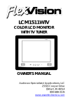
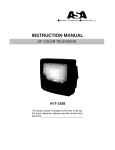
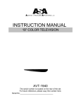
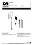
AWM-710 OWNER’S MANUAL
AM/FM STEREO/CASSETTE PLAYER
DESIGNED SPECIFICALLY FOR
THE VAN AND RV INDUSTRIES
CAUTION
RISK OF ELECTRIC SHOCK
DO NOT OPEN
CAUTION: TO REDUCE THE RISK OF ELECTRICAL SHOCK, DO NOT REMOVE COVER (ON BACK). NO USER- SERVICIBLE
PARTS INSIDE. REFER SERVICING TO QUALIFIED PERSONNEL.
The lightning flash and arrowhead within
the triangle is alerting you of “dangerous
voltage” inside the product.
The exclamation point within the triangle is
A warning sign alerting you of important
Instructions accompanying the product.
WARNING: TO PREVENT FIRE OR SHOCK HAZARD, DO NOT EXPOSE THIS APPLIANCE TO RAIN OR MOISTURE.
DO NOT REMOVE COVER. PILOT LAMPS SOLDERED IN PLACE. NO USER SERVICABLE PARTS INSIDE. REFER
SERVICING TO QUALIFIED PERSONNEL.
IMPORTANT NOTES
Avoid installing the unit in locations described below:
- Places exposed to direct sunlight or close to heat
radiating appliances such as electric heaters.
- On top of other stereo equipment that radiates too
much heat.
- Places lacking ventilation or dusty places.
- Humid or moist places
Read owner’s manual before operating.
Be sure all connections are properly made
Before turning power on.
IDENTIFICATION OF CONTROL/CONNECTIONS
18
17
16
1
15
2
3
4
5
6
7
8
9
14 13 12
11
10
1
1. Power / Volume Knob
2. Band Select Button / Band Indicators
3. Station Indicator / No Back lighting
4. Tuning Control
5. AM Trimmer
6. Auxiliary Button
7. Stereo / Mono Button
8. Local / Distance Button
9. Tape Indicator
10. Cassette Player
11. Cassette Eject / Fast Forward Button
12. Speaker Select
13. Balance Slider
14. Tone Slider
15. Car Antenna Jack 75Ω
Ω
16. FM Antenna Terminals
17. RCA Auxiliary Input Jacks
18. Harness
INSTALLATION AND HOOK-UP
1. Cut mounting hole in desired location using mounting hole
diagram (right).
2. Route power, speaker, and antenna cables through hole
and connect to unit as shown below.
3. After making sure connections are correct, test unit
operation as described in operation section.
4. For best AM reception, AM trimmer must be adjusted.
12 PIN FEMALE CONNECTOR
WIRING COLOR CODE
FOR AWM-710
COLOR
ORANGE/WHITE
BLACK/WHITE
WHITE
VIOLET
BLUE
LIGHT GREEN
RED
VIOLET/BLACK
YELLOW
LT.GREEN/BLACK
FUNCTION
+12VDC IGNITION HOT
GROUND
A SPEAKER LEFT (+)
A SPEAKER LEFT (-)
A SPEAKER RIGHT (+)
A SPEAKER RIGHT (-)
B SPEAKER LEFT (+)
B SPEAKER LEFT (-)
B SPEAKER RIGHT (+)
B SPEAKER RIGHT (-)
Notes:
- When hooking up two speakers, hook A+ and A- speaker
wires to speaker select A speaker on switch. A & B and B
will not have any output at this time.
- B speakers are optional
- Speakers must have a minimum of four ohm impedance
each.
- Either antenna may be used. Both do not have to be hooked
up at the same time.
- Do not operate this unit with only one speaker hooked up. If
a speaker fails, replace it before operating this unit.
NOTE: Always be sure when running cables to avoid sharp edges, extreme heat sources, and any other potential hazards.
2
OPERATING INSTRUCTIONS
Note: Number in parenthesis (#) correspond with “Identification of Controls/Connections” on page 1 of this manual.
Tuner
1)
2)
3)
4)
5)
6)
7)
Turn power on by turning the Power Switch/Volume Control knob (1) clockwise.
Use the Band Selector (2) to select either AM or FM.
Use the Speaker Selector Switch (12) to choose speaker output.
Use the Tuner Control (4) to select station.
Adjust Volume Control (1) to suit taste.
If reception is faint, you may improve reception by pressing the Local/Distance Button (8) in.
You may also improve reception on a faint station by pushing the Stereo/Mono Button (7) to the “off” position. This puts the radio in
mono mode, and you will not receive stereo reception. The Stereo Light (to the right of the Station Indicator) will light up if you are
receiving a stereo signal.
Cassette Tape Player
1)
2)
3)
4)
5)
6)
7)
8)
Turn power on by turning the Power Switch / Volume Control knob (1) clockwise.
Use the Speaker Selector Switch (12) to choose speaker output.
Press the Cassette Eject Button (11) to eject any cassettes that may already be in the player.
Insert a cassette into the Cassette Player (10).
The cassette will automatically play when inserted.
The Tape Indicator (9) will light up when a cassette is in use.
You may fast forward the cassette by pressing the Fast Forward / Eject Button (11) halfway in.
To eject the cassette, press the Cassette Eject Button (11).
Auxiliary Input
1) Turn the power on by turning the Power Switch / Volume Control knob (1) clockwise.
2) Push the Auxiliary Switch (6) on.
3) If there is an external source (example: CD shuttle) connected to the Auxiliary In Jacks (17) on the rear of the radio, then you can
listen to your external source through the system.
3
AM ANTENNA TRIMMER ADJUSTMENT
For best reception, the AM ANT trimmer must be adjusted following the directions below:
AM Antenna Trim Adjustment
1) Turn radio ON.
2) Select AM.
3) Tune the radio to a weak station between 1200KHz and 1400KHz. If you can’t find a station in this range, find any other strong
station, and adjust tuning knob so that the radio is slightly off station. Turn volume control to maximum setting.
4) Using a small flat tip screwdriver, gently turn the trimmer for maximum volume.
IMPORTANT CASSETTE DECK PRECAUTIONS
-
Do not use 120 minute (c-120) cassettes in this unit
Clean cassette mechanism after every 60 hours of operation. Use only a commercial cassette tape cleaning cartridge.
Do not use cassette deck if temperature is below freezing. Allow the unit to warm up first.
Be sure cassette tape is tight before inserting into a cassette deck. See Diagram A below.
Cassette tapes cannot be recorded onto if the protect tabs have been broken off. See Diagram B below. If you want to protect a
tape from being accidentally erased, break off protect tab corresponding to that side.
SIDE 2
Diagram A
4
Diagram B
SIDE 1
Specifications
Size:
Overall Size:
Mounting Size:
10.43 (W) x 7” (H) x 6.25” (D)
265mm (W) x 178mm (H) x 159mm (D)
9.25” (W) x 6.05” (H) x 5.25” (D)
235mm (W) x 154mm (H) x 133mm (D)
Operating Voltage:
10 to 16 Volts DC
Current Draw:
125mA @ 12VDC
170mA @ 24VDC
Output Wiring:
2/4 Speaker and Headphone system
Output Impedance:
Compatible with 4 to 8 Ω speakers, 4Ω load minimum
Tuning Range:
(AM) 530 - 1720KHz
(FM) 87.5 - 107.9MHz
Sensitivity:
(AM) less than 30uV
(FM) less than 5uV
FM Stereo Separation:
More than 24dB
Frequency Response:
40 – 12,000Hz
Wow & Flutter:
0.15%
Tape S/N Ratio:
50dB standard tape
*Specifications may change without notice
5
Accessory List
Description
AVT-988 9” Color Television with Remote (12V)
AVT-597 5” Color Television with Remote (12V)
AVT-1498 13” Color Television with Remote (12V)
AVP-7000 Video Cassette Player (12V)
AVP-7285 Video Cassette Player (12V)
Wireless Headphone Kit: Includes 2 sets Wireless Headphones and Transmitter
BPA-501-12 4 Amp Adapter for use with AVT-988 9” and AVT-1498 13” Televisions
AC2A- 2 Amp Adapter for use with AVT-597 5” TV and AVP-7000 Video Cassette Player
Unified Remote Control
VAC-21- 12 Volt Corded Vacuum
AVF-1 12 Volt Rechargeable Flashlight
HP-175 Headphones with Pivoting Ear Cup
HP-275 Headphones with Volume Control on Cord
HP-375 Studio Quality Headphones
Part Number
AVT988
AVT597
AVT1498
AVP7000
AVP7285
WRFKIT1
0891412
0891436
0892325
VAC21
AVF1
HP175
HP275
HP375
Unlike household electronics, all of our products have been specifically designed and tested for the mobile environment and are only
available through ASA. To order any of these products, please contact Audiovox Specialized Applications at www.asaelectronics.com
or 800-688-3135.
23319 Cooper Dr. Elkhart, IN 46514
Phone: 800-688-3135 FAX 219-264-3007
Rev. C 12/00