1
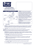
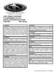
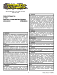
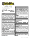
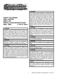
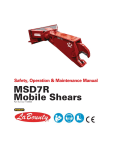
WARNING
Many states and municipalities have laws restricting
bumper heights and vehicle lifts. Consult state and
local laws to determine if the changes you intend to
make to the vehicle comply with the law.
3651 N. Highway 89 • Chino Valley, AZ 86323
(928) 636-7080 • www.p-a-g.net
WARNING
The installation of larger tires may reduce the effectiveness of the braking system.
DODGE RAM 1500 4WD
2” FRONT LEVELING KIT
INSTALLATION INSTRUCTIONS
‘06 - ’09
KIT# DL225PA
WARNING
Always wear eye protection when operating power
tools.
WARNING
Before you install this kit, block the vehicle tires to prevent the vehicle from rolling.
WARNING
WARNING
DO NOT combine suspension, body, or other lift
devices. Use of vehicle with combined lifts may result
in unsafe and/or unexpected handling characteristics.
Installation of a Performance Automotive Group suspension lift kit will change the vehicle’s center of gravity
and handling characteristics both on- and off-road. You
must drive the vehicle safely! Extreme care must be
taken to prevent vehicle rollover or loss of control,
which could result in serious injury or death. Avoid sudden sharp turns or abrupt maneuvers and always make
sure all vehicle occupants have their seat belts fastened.
NOTE
Lift height may vary depending on vehicle configuration, engine size, additional accessories, the factory
suspension package, and vehicle’s condition.
WARNING
Before you install this kit, read and understand all
instructions, warnings, cautions, and notes in this
instruction sheet and in the vehicle owner’s manual.
CAUTION
Proper installation of this kit requires knowledge of the
factory recommended procedures for removal and
installation of original equipment components. We recommend that the factory shop manual and any special
tools needed to service your vehicle be on hand during
the installation. Installation of this kit without proper
knowledge of the factory recommended procedures
may affect the performance of these components and
the safety of the vehicle. We strongly recommend that
a certified mechanic familiar with the installation of similar components install this kit.
WARNING
This kit should only be installed on a vehicle that is in
good working condition. Before you install the kit, thoroughly inspect the vehicle for corrosion or deformation
of the sheet metal. If the vehicle is suspected to have
been in a collision or misused, do not install this kit.
Off-road use of your vehicle with this kit installed may
increase the stress applied to the factory components.
Failure to observe this warning may result in serious
personal injury and/or severe damage to your vehicle.
1
‘06-’09 1500 Front Leveling - Kit DL225
Before Starting Installation
Ride Height
1. Measure ride height with the vehicle supporting its
own weight on level ground. To settle the suspension, the vehicle should be driven forward at least 10
feet immediately prior to taking these measurements. Ride height is the measurement from the
center of the axle straight up (vertical) to the fender
lip. Record this measurement for all four wheels.
NOTE
Kit parts are prefaced by the word kit and appear in
bold print.
1. Carefully read all warnings and instructions completely before beginning.
Fender
Lip
2. Verify all parts have been received in this kit by
checking the parts list at the end of this document.
3. Only install this kit on the vehicle for which it is
specified. If anytime during the installation you
encounter something different from what is outlined
in the instructions, call technical support at (928)
636-3175.
Measure
4. Special tools needed:
a. Coil spring compressors
Axle
Center
b. Tie rod puller
5. Park vehicle on a clean, dry, flat, level surface and
block tires so vehicle cannot roll in either direction.
Torque Specifications
NOTE
1. See factory service manual for torque values when
re-using OE fasteners.
Adhere to recommendations when replacement fasteners, retainers and keepers are called out in the factory
service manual. When re-assembling the vehicle it is
recommended by the vehicle manufacturer that certain
fasteners are replaced in order to maintain proper
retention characteristics. This system may not include
all replacement hardware as recommended by the factory service manual. Additional replacement hardware
should be obtained prior to installation of this system to
meet the requirements of the factory service manual.
Bolt Size
1/4”-20
1/4”-28
5/16”-18
5/16”-24
3/8”-16
3/8”-24
7/16”-14
7/16”-20
1/2”-13
1/2”-20
9/16”-12
9/16”-18
5/8”-11
5/8”-18
3/4”-16
2
Grade 5 (ft.-lbs.)
10
10
17
20
30
35
50
55
75
55
105
115
150
160
175
Grade 8 (ft.-lbs.)
10
12.5
22.5
25
40
45
65
70
100
70
135
150
195
210
225
‘06-’09 1500 Front Leveling - Kit DL225
Engine Compartment
4. Remove two nuts, two washers, two bushings, and
sway bar from driver and passenger sway bar end
links.
1. Disconnect both battery cables. Disconnect negative
cable first, then positive cable.
Positive
Cable
Battery
Negative
Cable
Sway Bar
Prepare to Install Kit
Nut, Washer
& Bushing
WARNING
Compressed coil springs can expand violently causing
serious personal injury. Use caution when using coil
spring compressors.
Sway Bar
End Link
1. Loosen, but do not remove, lug nuts on each front
wheel.
5. Driver coil-over assembly
2. Using a hydraulic floor jack, slowly lift front axle until
front tires are 3-5” off ground. Position jack stands
under frame. Lower vehicle onto jack stands while
maintaining hydraulic jack pressure underneath front
of vehicle.
NOTE
It may be necessary to use a tie rod puller to remove
steering tie rod end from steering knuckle.
a. Remove nut and steering tie rod end from steering knuckle.
WARNING
Tie Rod
Use extreme caution when lifting vehicle from ground.
To prevent serious personal injury, ensure the lifting
device is securely placed.
3. Remove lug nuts and front wheels from vehicle.
Knuckle
Nut
3
‘06-’09 1500 Front Leveling - Kit DL225
Install Kit
b. Remove nut and upper A-arm from steering
knuckle.
1. Coil spacers
Upper
A-Arm
WARNING
Compressed coil springs can expand violently causing
serious personal injury. Use caution when using coil
spring compressors.
Knuckle
a. Paint upper plate, ramp, coil spring, isolator, and
shock with alignment mark for proper re-assembly.
Nut
Upper Plate,
Ramp,
Spring,
Isolator
c. Remove nut and bolt from coil-over assembly
and lower A-arm.
Coil-Over
Assembly
Alignment
Mark
Nut & Bolt
Shock
b. Using coil spring compressors, compress coil
spring until shock is loose on coil spring.
Lower
A-Arm
Coil Spring
Compressor
d. Remove three nuts and coil-over assembly from
upper perch.
Nuts
Coil Spring
Upper
Perch
Shock
c. Remove nut and shock from coil spring and
upper plate.
Coil-Over
Assembly
Upper
Plate
e. Repeat above substeps for passenger coil-over
assembly.
Nut
4
‘06-’09 1500 Front Leveling - Kit DL225
g. Compress coil spring and align previously
painted alignment marks and install shock onto
upper plate with nut.
NOTE
When removing shock from upper plate, ensure metal
ring is seated on shock rod step.
Kit Spacer
Shock Rod
Nut
Metal Ring
Upper
Plate
d. Uncompress coil spring and remove upper plate
and isolator from ramp and coil spring.
Alignment
Marks
e. Install kit spacer onto isolator and upper plate.
h. Repeat above substeps for passenger coil
spacer.
Isolator
Upper
Plate
Kit Spacer
f.
Align previously painted alignment marks and
install upper plate, kit spacer, and isolator onto
ramp and coil spring.
NOTE
When installing shock onto upper plate, ensure metal
ring is seated on shock rod step.
5
‘06-’09 1500 Front Leveling - Kit DL225
2. Driver coil-over assembly
e. Install steering tie rod end onto steering knuckle
with nut. TORQUE to O.E. specification.
a. Install coil-over assembly onto upper perch with
three nuts. DO NOT TIGHTEN.
Tie Rod
Nuts
Knuckle
Upper
Perch
Nut
Coil-Over
Assembly
f.
b. Install coil-over assembly onto lower A-arm with
bolt and nut. TORQUE to O.E. specification.
Repeat above substeps for passenger coil-over
assembly.
CAUTION
Coil-Over
Assembly
DO NOT OVER COMPRESS sway bar bushings in the
following step. Damage may occur to bushings, sway
bar, or sway bar end links.
Nut & Bolt
3. Install sway bar onto driver and passenger sway bar
end links with two bushings, two washers, and two
nuts. TIGHTEN two nuts until bushings are
SLIGHTLY COMPRESSED.
Lower
A-Arm
Nut, Washer
& Bushing
c. TORQUE three upper perch nuts to O.E. specification.
Sway Bar
d. Install upper A-arm onto steering knuckle with
nut. TORQUE to O.E. specification.
Sway Bar
End Link
Upper
A-Arm
4. Install front wheels onto vehicle with lug nuts. Snug,
but DO NOT TIGHTEN.
Knuckle
5. Using hydraulic floor jack, raise front of vehicle and
remove jack stands. Slowly lower vehicle onto
ground.
Nut
6. TORQUE front lug nuts to specification.
6
‘06-’09 1500 Front Leveling - Kit DL225
After Completing Installation
CAUTION
Performance Automotive Group does not recommend
any particular wheel and tire combinations for use with
its suspension lifts and cannot assume responsibility
for the customer’s choice of wheels and tires. Refer to
your owner's manual for recommended tire sizes and
warnings related to the use of oversized tires. Larger
wheel and tire combinations increase stress and wear
on steering and suspension components, which leads
to increased maintenance and higher risk for component failure. Larger wheel and tire combinations also
alter speedometer calibration, braking effectiveness,
center of gravity, and handling characteristics. Consult
an experienced local off road shop to find what wheel
and tire combinations work best with your vehicle.
Engine Compartment
1. Connect both battery cables. Connect positive cable
first, then negative cable.
Positive
Cable
Battery
NOTE
Negative
Cable
All warranty information, instruction sheets, and other
documents regarding the installation of this product
must be retained by the vehicle owner. Information
contained in the instructions and on the warranty card
will be required for any warranty claims. The vehicle
owner needs to understand the modifications made to
the vehicle and how they affect vehicle handling and
performance. Failure to provide the customer with this
information can result in damage to the vehicle and
severe personal injury.
Miscellaneous
1. Apply kit label (warning) onto dashboard in plain
sight of all vehicle occupants.
2. Adjust headlights.
3. Check all fasteners to ensure they are tight.
4. Ensure all wires, hoses, cables, etc. are properly
connected and there is ample slack.
Kit Parts List
5. Align vehicle to OE specifications. Retain alignment
results.
Qty. Description
Dynamic Vehicle Check
2
Spacer
1. Check steering and suspension in all positions to
ensure that there is no bind and adequate clearance
between all moving, fixed, and heated members.
Check operation of clutch, brake system, and parking brake. Check operation of transmission and
transfer case. Ensure there is full engagement in all
gears and 4WD ranges. Check battery connections
and electrical component operations. Test-drive
vehicle.
WARNING
Retorque all fasteners after 500 miles and after off road
use. All suspension lift components should be visually
inspected and fasteners retorqued during routine vehicle servicing.
Copyright 06/06
Performance Automotive Group
www.p-a-g.net
7
‘06-’09 1500 Front Leveling - Kit DL225