1
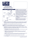
3651 N Highway 89 • Chino Valley, AZ 86323
(928) 636-7080
WARNING
DODGE DAKOTA
3” KIT
INSTALLATION INSTRUCTIONS
2000-2002
KIT# 60043
This kit should only be installed on a vehicle that is in
good working condition. Before you install the kit, thoroughly inspect the vehicle for corrosion or deformation
of the sheet metal around the factory body mounts. If
the vehicle is suspected to have been in a collision or
misused, do not install this kit. Off-road use of your
vehicle with this kit installed may increase the stress
applied to the factory body mounts. We do not recommend that any vehicle with a body lift kit installed be
involved in any extreme off-road maneuvers such as
jumping. Failure to observe this warning may result in
serious personal injury and/or severe damage to your
vehicle.
WARNING
Many states and municipalities have laws restricting
bumper heights and vehicle lifts. Consult state and
local laws to determine if the changes you intend to
make to the vehicle comply with the law.
WARNING
Installation of a Performance Automotive Group body
lift kit will change the vehicle’s center of gravity and
handling characteristics both on- and off-road. You
must drive the vehicle safely! Extreme care must be
taken to prevent vehicle rollover or loss of control,
which could result in serious injury or death. Avoid sudden sharp turns or abrupt maneuvers and always make
sure all vehicle occupants have their seat belts fastened.
WARNING
The installation of larger tires may reduce the effectiveness of the braking system.
WARNING
Always wear eye protection when operating power
tools.
WARNING
Before you install this kit, read and understand all
instructions, warnings, cautions, and notes in this
instruction sheet and in the vehicle owner’s manual.
WARNING
Before you install this kit, block the vehicle tires to prevent the vehicle from rolling.
CAUTION
WARNING
Proper installation of this kit requires knowledge of the
factory recommended procedures for removal and
installation of original equipment components. We recommend that the factory shop manual and any special
tools needed to service your vehicle be on hand during
the installation. Installation of this kit without proper
knowledge of the factory recommended procedures
may affect the performance of these components and
the safety of the vehicle. We strongly recommend that
a certified mechanic familiar with the installation of similar components install this kit.
Accidental deployment of the air bag can result in serious personal injury or death. To avoid accidental
deployment during installation of the kit, the Supplemental Restraint System (SRS, or airbag) must remain
deactivated. Do not allow anyone near the airbag during installation. Refer to the factory service manual or
owner's manual for the recommended procedure to
disable the SRS. After you install the kit, reactivate the
SRS before driving the vehicle.
NOTE
WARNING
Performance Automotive Group recommends using
the Loctite® supplied in the kit on the threads of all kit
nuts and bolts unless specified otherwise in these
instructions.
DO NOT combine suspension, body, or other lift
devices. Use of vehicle with combined lifts may result
in unsafe and/or unexpected handling characteristics.
1
‘00-’02 Dakota - Kit 60043
A. Before you start
NOTE
As you read through this procedure, note that each
part referenced has the same callout number throughout. Also, the part number in the text matches the corresponding part number in the art. Kit parts are
prefaced by the word kit in italics.
1. Read all warnings and instructions completely and
carefully before you begin.
2. Check to make sure the kit is complete (refer to the
Parts List, section E).
3. Only install this kit on the vehicle for which it is
intended. If anytime during the installation you
encounter something different from what is outlined
in the instructions, call technical support at (928)
636-7080.
4. Park the vehicle on a clean, dry, flat, level surface
and block the tires so the vehicle cannot roll in either
direction.
5. Lower spare tire (1) to the ground (refer to the
owner’s manual).
a. Remove clip (2) and crank rod (3) from winch (4).
b. Remove crank rod (3) and plastic collar (5) from
bed (6).
6. Disconnect both battery cables. Disconnect the negative cable (7) first, then the positive cable (8).
Remove battery (9) from vehicle (refer to the
owner’s manual).
WARNING
Accidental deployment of the air bag can result in serious personal injury or death. To avoid accidental
deployment during installation of the lift kit, the Supplemental Restraint System (SRS, or airbag) must remain
deactivated. Do not allow anyone near the airbag during installation. Refer to the factory service manual or
owner's manual for the recommended procedure to
disable the SRS. After kit installation, the SRS must be
reactivated before driving the vehicle.
7. Remove two air bag fuses (10) from the fuse box
(11) (see the owner’s manual for fuse location).
2
‘00-’02 Dakota - Kit 60043
B. Get ready to install the kit.
1. Manual Transmission Models: Shift Lever
Upper Shift
Boot
a. Remove six screws and upper shift boot from shift
console. Slide shift boot up the upper shift lever.
b. Remove upper shift lever from lower shift lever.
Remove upper shift lever and upper boot from vehicle.
Upper Shift
Lever
Screw
c. Remove six screws and shift console from cab
floor.
d. Remove six screws and lower shift boot from cab
floor.
Shift Console
e. Remove dust cover, four screws, and locking
plate from shift tower.
f. Remove locking plate, washer, lower shift lever,
pivot pins, and insulator from shift tower.
Lower Shift Lever
Screw
Screw
Shift Console
Lower Shift Boot
Screws
Dust Cover
Locking Plate
Not Shown
Washer
Locking Plate
Lower Shift Lever
Pivot Pins
Screw
Shift Tower
Shift Tower
Insulator
3
‘00-’02 Dakota - Kit 60043
2. 4WD Models: Remove the shift transfer case shift
linkage.
a. If present on your vehicle, remove four bolts (12)
and skid plate (13) from the frame (14) under the
transmission and transfer case.
b. Remove two rubber bushings (15) and transfer
case shift linkage (16) from shift lever (17) and transfer case (18).
3. Remove the front bumper.
a. Remove nine panel clips (19), plastic cover (20),
and rubber cover (21) from the core support (22).
b. If present on your vehicle, disconnect two wire
harness connectors (23) from the driving lights (24).
c. Remove four nuts (25), bolts (26), and two front
bumper outer brackets (27) from the frame (14).
d. Remove four bolts (28) and front bumper (29)
from two frame (30) inner mounts.
4
‘00-’02 Dakota - Kit 60043
4. Remove the rear bumper.
a. Disconnect two wire harness connectors (31) from
the license plate lights (32).
b. Remove six nuts (33) and rear bumper (34) from
the frame (14).
5. Remove the fan shroud.
a. Drain the radiator (35) into a clean pan (refer to
the owner’s manual).
b. Remove four wire harness clips (36) and wire harness (37) from the core support (38).
5
‘00-’02 Dakota - Kit 60043
c. Disconnect two connectors (38 and 39) and
washer fluid hose (40) from the fan shroud (41).
d. Remove four bolts (42) and the fan (43) from the
water pump (44) and allow fan to rest inside the
shroud.
e. Remove four bolts (45) and fan shroud (41) from
the radiator (35) and allow shroud to rest against the
engine.
f. Remove fan shroud (41) and fan (43) from the
vehicle and separate upper fan shroud (41) from
lower fan shroud (46).
h. Cut the lip from the lower fan shroud (46) as
shown.
6
‘00-’02 Dakota - Kit 60043
6. Remove firewall mounted ground wires.
a. Ensure two ground wires (47) on the firewall (48)
have ample slack to allow for lifting. Ensure ground
wire on driver’s side is routed over the brake booster
(49).
b. If ground wire on the driver’s side is not routed
over the brake booster (49), remove two nuts (50)
and reroute the ground wires (47).
c. Install two ground wires (47) on the firewall (48)
with two nuts (49).
7. Driver’s side frame rail.
a. Remove plastic cover (50) from driver’s side front
wheel well (51) and top of the frame rail (52).
b. Remove wire harness panel clip (53) from the top
of the frame rail (52).
c. Remove brake lines (54) from plastic clips (55) on
the frame rail (52).
d. Remove two bolts (56) and brake line bracket (57)
from the frame rail (52).
e. If equipped with automatic transmission, remove
automatic transmission cable (58) from the automatic transmission cable loop (59) on the driver’s
side front wheel well (51). Ensure cable has ample
slack to allow for lifting.
f. Remove bolt (60) and loop (59) from driver’s side
front wheel well (51).
7
‘00-’02 Dakota - Kit 60043
CAUTION
If the following step is not performed, the airbag clockspring could be damaged. Do not turn the steering
wheel while the steering shaft is disconnected.
Ensure steering shaft does not turn independently of the
steering gearbox. This could cause the air bag system to
malfunction, resulting in serous personal injury or damage to the equipment.
8. Remove steering shaft.
a. Remove bolt (61), loosen bolt (62), and remove
steering shaft (63) from top of the steering rack (64
and 65).
WARNING
Use extreme caution when working near the fuel lines
and the fuel tank. Clean up spilled fuel immediately. A
spark could cause an explosion or fire resulting in serious personal injury and property damage.
9. Remove the fuel filler hose.
a. Remove gas cap (66). Remove three screws
(67), bend two tabs (68), and let fuel filler neck (69)
drop down from the bed (6).
b. Remove two clamps (70), fuel filler hose (71), and
vent hose (72) from the fuel tank (73).
8
‘00-’02 Dakota - Kit 60043
C. Install the kit.
1. Prepare to lift cab from frame.
WARNING
Use extreme caution when lifting body from frame. To
prevent serious personal injury, ensure the lifting
device is securely placed. Keep your hands out from
between the body and frame.
a. Measure distance between the cab (74) and the
bed (6). Record measurement for later cab to bed
alignment reference in the instructions.
b. Loosen but do not remove eight cab mounting
bolts (75).
CAUTION
Continually check hoses, wires, lines, etc. to be sure
that everything is flexing properly and not binding, or
damage to the vehicle could result. Be especially careful of the a/c hoses at the fire wall, the belt pulley, and
at the core support. Ensure brake lines stretch while
lifting. Bending the lines to gain ample slack may be
necessary. Be extremely careful not to kink the lines.
WARNING
The kit blocks must be installed in addition to the factory upper and lower bushings. Installing the kit blocks
without the factory upper and lower bushings could
result in damage to the vehicle or serious personal
injury.
c. Remove bolt (76) and washer (77) from the passenger side core support frame mounting pad (78).
d. Remove three bolts (76) and washers (77) from
the passenger side frame mounting pads (78) and
cab mounting pads (79).
9
‘00-’02 Dakota - Kit 60043
2. Lift cab and install cab passenger side spacer
blocks.
a. Using a hydraulic jack and a wooden block, slowly
lift the cab (74) passenger side just high enough to
position the kit spacer blocks (80) on the frame
mounting pads (78).
b. Position four kit spacer blocks (80) on top of the
passenger side core support and frame mounting
pads (78).
c. Install a kit 12mm x 160mm bolt (81) (12mm x
140mm for a 2" kit) and a kit 1/2" USS washer (82)
through the bottom bushing retainer (83), bottom
bushing (84), frame mounting pad (78), upper bushing (85), upper bushing retainer (86), kit spacer
block (80), and in the body mounting pad (87). Do
not tighten.
d. Lower cab (74) on the kit spacer blocks (80).
3. Install the cab driver’s side spacer blocks.
a. Repeat steps C. 2. a. through d. for the cab
driver’s side.
4. Finish the cab spacer block installation.
a. Adjust cab to bed clearance using the measurements from step C. 1. a.
b. Remove eight bolts (81) one at a time, coat
threads with Loctite®, and reinstall. Tighten to 55 lbft.
10
‘00-’02 Dakota - Kit 60043
5. Install the bed passenger’s side spacer blocks.
a. Loosen but do not remove eight bed mounting
bolts (88).
b. Remove four bolts (88) from the bed (6) passenger side.
c. Using a hydraulic jack and a wooden block, slowly
lift the bed (6) passenger side just high enough to
position the kit spacer blocks (89 and 90) on the
frame (14). The small spacer blocks (90) go on the
rearmost mounts.
d. Install a kit 10mm x 100mm bolt (91) (10mm x
80mm for a 2" kit), a kit 7/16" USS washer (92), and
a kit 3/8” washer (93) through the frame mounting
pad (78), kit spacer block (89 or 90), and in the bed
mounting pad (94). Do not tighten.
e. Lower the bed onto the spacer blocks (89 and 90).
6. Install the bed driver’s side spacer blocks.
a. Repeat steps C. 5 a. through e. for the bed
driver’s side.
7. Finish the bed spacer block installation.
a. Adjust the cab to bed clearance using the measurements from step C. 1. a.
b. Remove eight bed mounting bolts (91) one at a
time, coat threads with Loctite®, and reinstall.
Tighten to 55 lb-ft.
11
‘00-’02 Dakota - Kit 60043
WARNING
Use extreme caution when working near the fuel lines
and the fuel tank. Clean up spilled fuel immediately. A
spark could cause an explosion or fire resulting in serious personal injury and property damage.
8. Install the fuel filler hose.
a. Install fuel filler hose (71) and vent hose (72) on
fuel tank (73) with two clamps (70).
b. Position fuel filler neck (69) in bed (6), straighten
tabs (68), and install three screws (67). Bend tabs
over screws. Install gas cap (66).
9. Install kit steering extension.
WARNING
Verify the steering extension is securely installed as
specified in the instructions. Failure to do so may
cause steering malfunction, resulting in property damage or serious personal injury.
a. Coat threads of retaining bolts (61, 62, and 95)
with Loctite®.
b. Install kit steering extension (96) on steering rack
(64 and 65) with the kit retaining bolt (95). Do not
tighten.
c. Install steering shaft (63) on kit steering extension
(96 or 97) with the stock retaining bolt (61).
d. Tighten bolts (61, 62, and 95) to 20 lb-ft.
12
‘00-’02 Dakota - Kit 60043
10. Install the fan shroud.
a. Remove two clamps (98) and lower radiator hose
(99). Turn hose 180 degrees and reinstall.
b. Join upper fan shroud (41) and lower fan shroud
(46).
c. Position fan (43) and fan shroud (41) in the vehicle.
d. Install fan shroud (41) on the radiator (35) with
four bolts (45). Do not tighten.
e. Install fan (43) on the water pump (44) with four
bolts (42).
f. Adjust fan to fan shroud and fan to hose clearance. Ensure fan cannot contact hoses or the fan
shroud. Tighten four bolts (45).
g. If lower radiator hose (99) appears to be too close
to fan (43), cut hose and install hose extension (99a)
with two kit clamps (99b).
h. Connect washer fluid hose (40) and two connectors (38 and 39) on the fan shroud (41).
i. Fill radiator (35) (refer to the owner’s manual)
13
‘00-’02 Dakota - Kit 60043
i. Install four wire harness clips (36) in core support
(22) holes where possible.
j. Use kit zip ties (100) to secure wire harness (37) to
the a/c lines (101).
11. Check battery positive cable (8) length. If positive
cable is not long enough to reach the battery (9):
a. Remove bolt (102) and cable (8) from frame rail
(52).
b. Install kit extension strap (103) on frame rail (52)
with bolt (102).
c. Install cable (8) on kit extension strap (103) with
kit bolt (104), lock washer (105), and nut (106).
d. Strap cable (8) to the power steering hose (107)
with kit zip tie (108).
14
‘00-’02 Dakota - Kit 60043
12. Install the front bumper.
a. Coat threads of bolts (26, 28, 111, and 114) with
Loctite®.
b. Install two kit inner front bumper brackets (109) on
frame (14) inner mounts with four bolts (28) (the “C”
should open to the rear of the vehicle). Center
brackets on mounts and tighten bolts to 55 lb-ft.
c. Install two kit outer brackets (110) on the frame
(14) with four bolts (26) and nuts (25). Do not
tighten.
d. Install front bumper (29) on two kit inner brackets
(109) with four kit 7/16” x 1 1/2” bolts (111), eight 7/
16” USS washers (112), and four 7/16” nylock nuts
(113). Insert bolts with heads facing center of vehicle. Do not tighten.
e. Install front bumper (29) outer brackets (27) on
two kit outer brackets (110) with four 7/16” x 1” bolts
(114), eight 7/16” USS washers (115), and four 7/16”
nylock nuts (116). Insert bolts with heads facing center of vehicle. Do not tighten.
f. Adjust bumper to body clearance and tighten bolts
(26, 28, 111, and 114) to 55 lb-ft.
g. If removed, connect two wire harness connectors
(23) on driving lights (24).
h. Install rubber cover (21) and plastic cover (20) on
core support (22) with nine panel clips (19).
15
‘00-’02 Dakota - Kit 60043
13. Install the rear bumper.
WARNING
The following procedure is intended only to enhance
the appearance of the vehicle. The rear bumper will no
longer be rated for towing of any kind. Towing with the
rear bumper after it has been lifted can result in death,
serious personal injury, or damage to the vehicle. Towing after the bumper has been lifted should be accomplished using a rated Class III receiver type hitch.
a. Coat threads of nuts (33) with Loctite®.
b. Install two kit brackets (117) on frame (14) with six
nuts (33).
c. Install rear bumper (34) on kit brackets (117) with
four nuts (33). Do not tighten.
f. Adjust bumper to body clearance and tighten nuts
(33) to 55 lb-ft.
g. Connect two wire harness connectors (31) on
license plate lights (32).
16
‘00-’02 Dakota - Kit 60043
14. Install brake lines.
CAUTION
Ensure brake lines stretch while lifting. Bending the
lines to gain ample slack may be necessary. Be
extremely careful not to kink the lines.
a. Check brake lines (54) removed from clips (55) on
the driver’s side frame rail (52). If necessary, carefully straighten lines to gain more slack.
b. Install kit bracket (118) on frame rail (52) with bolt
(56).
c. Install brake line bracket (57) on kit bracket (118)
with kit 5/16” bolt (119), three kit 5/16” washers (119)
and kit 5/16” nylock nut (120).
d. Install plastic clip (55) on bracket (57).
e. Install brake lines (54) in the plastic clips (55).
15. Reposition automatic transmission shift cable.
a. Install kit bracket (121) and automatic transmission cable loop (59) on the brake booster (49) with
two kit 1/4”x1” bolts (122), three kit 1/4” washers
(123), and a kit 8mm nylock nut (124).
b. Position automatic transmission cable (58) in the
automatic transmission cable loop (59).
17
‘00-’02 Dakota - Kit 60043
WARNING
A certified welder or welding shop should perform all
welding.
16. Lengthen and install the transfer case shift linkage.
a. Position 4WD shifter in neutral. Measure distance
center to center between holes in (17) and (18).
b. Measure length of linkage rod (16) and add 3” for
kit linkage extension (125). If total length of (16) and
(125) is greater than distance between (17) and
(18), shorten kit linkage extension (125) so measurements are equal.
c. Scribe a line along the transfer case linkage rod
(16). Cut linkage into two pieces through line.
d. Position kit linkage extension (125) between two
pieces of the linkage rod (16), align two halves of
scribed line, and weld extension in place.
e. Install transfer case shift linkage (16) on shift lever
(17) and transfer case (18) with two rubber bushings
(15).
f. If removed, install skid plate (13) on the frame (14)
with four bolts (12).
17. Manual Transmission Models: Shift Lever
a. Scribe a line along side of transmission shift lever
below bend as shown. Cut lever into two pieces
through line and de-burr as necessary.
Scribe A Line
18
Kit Extension
‘00-’02 Dakota - Kit 60043
b. Position kit extension transmission shift lever 5/8”
x 3” between two pieces of transmission shift lever.
Ensure kit extension and shift lever scribe lines
align and weld extension in place. Let shift lever
cool.
Dust Cover
c. Install insulator, two pivot pins, washer, and locking plate on modified lower shift lever. Position modified lower shift lever in shift tower.
Locking Plate
Screw
d. Install locking plate with four screws and dust
cover on shift tower.
Shift Tower
e. Install lower shift boot on cab floor with six screws.
Install shift console on cab floor with six screws.
f. Install upper shift lever on modified lower shift
lever. Install upper shift boot on shift console with six
screws.
Lower Shift Boot
Shift Console
18. Tack weld two kit bed overload spacers (126) on the
frame (14) over the rear wheel wells (127) as shown.
19
‘00-’02 Dakota - Kit 60043
D. After installation is complete.
1. Install two airbag fuses (10) in the fuse box (11).
2. Install battery (9) and connect both battery cables.
Be sure to reconnect the positive cable (8) first, then
the negative cable (9).
3. Install the spare tire (1).
a. To remount crank rod (3) on vehicle, drill a 5/16”
hole in the crossmember (128) as shown.
b. Install kit clamp (129) with kit 1/4” x 1” bolt (130),
kit 1/4” washer (131), and kit 1/4” nylock nut (132).
Ensure bolt is installed up toward bed.
c. Install crank rod (3) in kit clamp (129).
d. Remove license plate and drill 3/4” hole in plastic
part of rear bumper (34) as shown. Install plastic
collar (5). Ensure you can successfully lower crank
rod (3) through hole. Reinstall license plate.
4. Apply kit warning sticker on the dash in plain sight of
all vehicle occupants.
20
‘00-’02 Dakota - Kit 60043
5. Double check the vehicle.
WARNING
NOTE
Retorque all fasteners after 500 miles and after off road
use. All body lift components should be visually
inspected and fasteners retorqued during routine vehicle servicing.
All warranty information, instruction sheets, and other
documents regarding the installation of this product
must be retained by the vehicle owner. Information
contained in the instructions and on the warranty card
will be required for any warranty claims. The vehicle
owner needs to understand the modifications made to
the vehicle and how they affect vehicle handling and
performance. Failure to provide the customer with this
information can result in damage to the vehicle and
severe personal injury.
a. Check all mounting hardware to ensure it is properly tightened.
b. Check all wires, hoses, cables, etc. to ensure they
have been properly connected and there is ample
slack. With the number of hoses on this vehicle, it is
vital that this be checked thoroughly.
Accessories
c. Check vehicle electrical system.
d. Start vehicle and check the steering in both directions to ensure that there is no bind. Check clutch
operation. Check the operation of the brake system
and the parking brake. Check both shift levers’ operation. Ensure that there is proper engagement in all
gears and 4 wheel drive ranges.
Kit# 6617 Gap Guards
WARNING
If the engine cooling system is hot, the coolant will be
HOT and UNDER PRESSURE. To prevent serious
personal injury, wait until the cooling system is completely cool before removing the cap from the radiator.
e. Check coolant level. Fill coolant to the proper
level (refer to the Owner’s Manual).
f. Test drive vehicle in all gears and 4 wheel drive
ranges. Pay close attention to all vehicle systems.
Check all hardware again in 500 miles and as part of
your regular maintenance schedule.
g. Adjust headlights.
CAUTION
Performance Automotive Group does not recommend
any particular wheel and tire combinations for use with
its body lifts and cannot assume responsibility for the
customer’s choice of wheels and tires. Refer to your
owner's manual for recommended tire sizes and warnings related to the use of oversized tires. Larger wheel
and tire combinations increase stress and wear on
steering and suspension components, which leads to
increased maintenance and higher risk for component
failure. Larger wheel and tire combinations also alter
speedometer calibration, braking effectiveness, center
of gravity, and handling characteristics. Consult an
experienced local off road shop to find what wheel and
tire combinations work best with your vehicle.
21
‘00-’02 Dakota - Kit 60043
E. Kit Parts List.
Qty
Description
12
2
2
2
2
1
1
2
1
1
1
3 x 3 blocks
3 x 2 blocks
Front inner bumper brackets
Front outer bumper brackets
Rear bumper brackets
Brake line bracket
Transmission cable bracket
Overload spacers, no hole
Warning to driver sticker
Logo sticker
6ml bottle Loctite
1
8
8
8
8
1
1
Bolt pack BP60043
12mm x 160mm bolts
10mm x 100mm bolts
1/2” USS washers
7/16” USS washers
se 8700 steering extension
3/8” x 1 1/4” socket head bolt
1
Hardware pack HP60043
Bolts
7/16” x 1 1/2” bolts
7/16” x 1” bolts
5/16” x 1” bolt
1/4” x 1” bolts
Washers
7/16” USS washers
5/16” SAE washers
1/4” SAE washers
Nuts
7/16” nylock nuts
5/16” nylock nuts
1/4” nylock nut
8mm nylock nut
Miscellaneous
Transfer case linkage rod extension (1/2”
x 3”)
Manual shift lever extension (5/8” x 3”)
Lower radiator hose extension
Ground strap extensions
Rubber clad clamp
Zip ties
#36 clamps
4
4
1
4
6
3
5
8
1
2
1
1
1
1
1
1
3
2
Front bumper inner bracket
Front bumper outer bracket
Rear bumper bracket
Rev. 02, Copyright 08/05
Performance Automotive Group
22
‘00-’02 Dakota - Kit 60043