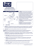
1
3651 N Highway 89 • Chino Valley, AZ 86323
(928) 636-7080 • www.p-a-g.net
WARNING
JEEP WRANGLER
JEEP WRANGLER UNLIMITED
2 & 4 DOOR
2” BODY LIFT KIT
** AUTO TRANSMISSION ONLY **
INSTALLATION INSTRUCTIONS
2007-2011
KIT# 992
This kit should only be installed on a vehicle that is in
good working condition. Before you install the kit, thoroughly inspect the vehicle for corrosion or deformation
of the sheet metal around the factory body mounts. If
the vehicle is suspected to have been in a collision or
misused, do not install this kit. Off-road use of your
vehicle with this kit installed may increase the stress
applied to the factory body mounts. We do not recommend that any vehicle with a body lift kit installed be
involved in any extreme off-road maneuvers such as
jumping. Failure to observe this warning may result in
serious personal injury and/or severe damage to your
vehicle.
WARNING
WARNING
Installation of a Performance Automotive Group body
lift kit will change the vehicle’s center of gravity and
handling characteristics both on- and off-road. You
must drive the vehicle safely! Extreme care must be
taken to prevent vehicle rollover or loss of control,
which could result in serious injury or death. Avoid sudden sharp turns or abrupt maneuvers and always make
sure all vehicle occupants have their seat belts fastened.
Many states and municipalities have laws restricting
bumper heights and vehicle lifts. Consult state and
local laws to determine if the changes you intend to
make to the vehicle comply with the law.
WARNING
The installation of larger tires may reduce the effectiveness of the braking system.
WARNING
WARNING
Before you install this kit, read and understand all
instructions, warnings, cautions, and notes in this
instruction sheet and in the vehicle owner’s manual.
Always wear eye protection when operating power
tools.
WARNING
CAUTION
Before you install this kit, block the vehicle tires to prevent the vehicle from rolling.
Proper installation of this kit requires knowledge of the
factory recommended procedures for removal and
installation of original equipment components. We recommend that the factory shop manual and any special
tools needed to service your vehicle be on hand during
the installation. Installation of this kit without proper
knowledge of the factory recommended procedures
may affect the performance of these components and
the safety of the vehicle. We strongly recommend that
a certified mechanic familiar with the installation of similar components install this kit.
WARNING
Accidental deployment of the air bag can result in serious personal injury or death. To avoid accidental
deployment during installation of the kit, the Supplemental Restraint System (SRS, or airbag) must remain
deactivated. Do not allow anyone near the airbag during installation. Refer to the factory service manual or
owner's manual for the recommended procedure to
disable the SRS. After you install the kit, reactivate the
SRS before driving the vehicle.
WARNING
DO NOT combine suspension, body, or other lift
devices. Use of vehicle with combined lifts may result
in unsafe and/or unexpected handling characteristics.
**Automatic Transmission Only**
NOTE
Performance Automotive Group recommends using
the Loctite® supplied in the kit on the threads of all kit
nuts and bolts unless specified otherwise in these
instructions.
1
2” Body Lift - Kit 992
Before Starting Installation
2. Airbag Fuse
NOTE
NOTE
Kit parts are prefaced by the word kit and appear in
bold print.
The location of the airbag fuse may vary; check the
owner's manual.
a. Remove fuse cover.
1. Carefully read all warnings and instructions completely before beginning.
b. Remove airbag fuse.
Fuse Block
2. Verify all parts have been received in this kit by
checking the parts list at the end of this document.
NOTE
If parts are missing from kit, please be prepared to provide the following information:
1. Name of purchase location
2. Bar Code on side of box
3. Date above bar code
4. Date inside box cover
5. Inspector # from inside box cover
3. Only install this kit on the vehicle for which it is
specified. If anytime during the installation you
encounter something different from what is outlined
in the instructions, call technical support at (928)
636-7080.
4. Park vehicle on a clean, dry, flat, level surface and
block tires so vehicle cannot roll in either direction.
Engine Compartment
1. Disconnect both battery cables. Disconnect negative cable first, then positive cable.
Positive Cable
**Automatic Transmission Only**
Negative Cable
2
2” Body Lift - Kit 992
Prepare to Install Kit
b. Remove six screw clips along top of grille.
Screw Clips
Front of Vehicle
Screw Clips
1. Grille
a. Unplug wire harness from two fog lamps. Slide
out red tab and disconnect wire harness.
Fog Lamp
Screw
Clips
Red Clips
c. Remove grille from vehicle by popping four clips
along bottom of grille.
Wire Harness
Grille
Clips
**Automatic Transmission Only**
3
Clips
2” Body Lift - Kit 992
Engine Compartment
b. Mark steering shaft u-joint in relation to steering
shaft as shown.
1. Wire Harness
a. Unclip wire harness on firewall at back of
engine.
Wire Harness
Bolt
Clips
Marks
Steering Shaft
2. Steering Shaft
WARNING
Accidental deployment of the air bag can result in serious personal injury or death. To avoid accidental
deployment during installation of the lift kit, the Supplemental Restraint System (SRS, or airbag) must remain
deactivated. Do not allow anyone near the airbag during installation. Refer to the factory service manual or
owner's manual for the recommended procedure to
disable the SRS. After kit installation, the SRS must be
reactivated before driving the vehicle.
c. Remove bolt and slide u-joint off of steering
shaft.
Install Kit
CAUTION
Body
If the following step is not performed, the airbag clockspring could be damaged. Do not turn the steering
wheel while the steering shaft is disconnected.
1. Prepare to lift body from frame
a. Strap steering wheel to prevent accidental
movement.
**Automatic Transmission Only**
4
2” Body Lift - Kit 992
a. Remove two nuts on front core support body
mount on driver side.
c. Remove two nuts on front core support body
mount on passenger side.
Remove These
Two Nuts
Body Mount
(Core Support)
Body Mount
(Core Support)
b. Driver Side: Loosen, but DO NOT REMOVE,
body mounting bolts. 2 Door - 4 body mount
bolts and 4 Door - 5 body mount bolts.
Remove These
Two Nuts
d. Passenger Side: Remove bolt and lower bushing from each cab mount on passenger side. 2
Door - 4 body mount bolts and 4 Door - 5 body
mount bolts.
Loosen Body Mount Bolts
on Drivers Side
Remove Body Mount Bolts
on Passenger Side
Body Mount
(Except Core Support)
Body Mount
(Except Core Support)
NOTE
The number of body mounting bolts may vary depending if vehicle is a 2 door or 4 door.
**Automatic Transmission Only**
5
2” Body Lift - Kit 992
e. Remove large washer from factory bolts by supporting large washer and tapping on the bolt.
b. Remove bottom nut on front core support
mount.
Factory Core
Support
Bushing
Bottom Support
Mount Nut
Remove Washer
from Bolt
c. Remove core support bushing from vehicle.
d. Remove the two bolts from core support mount
by tapping on them with a hammer.
Factory Core
Support
Bushing
WARNING
Use extreme caution when lifting body from frame. To
prevent serious personal injury, ensure the lifting
device is securely placed. Keep your hands out from
between the body and frame.
Remove Two
Bolt
CAUTION
Continually check hoses, wires, lines, etc. to be sure
that everything is flexing properly and not binding, or
damage to the vehicle could result. Be especially careful of the a/c hoses at the fire wall, the belt pulley, and
at the core support. Ensure brake lines stretch while
lifting. Bending the lines to gain ample slack may be
necessary. Be extremely careful not to kink the lines.
e. Place kit block (core support) on core support
mount.
Kit Block
(Core Support)
2. Passenger side
a. Position a hydraulic floor jack and a wood block
under passenger side of body (under the body
seam). Slowly lift body just enough to install a kit
block on top of factory upper bushing.
Core Support
Mount
WARNING
The kit blocks must be installed in addition to the factory upper and lower bushings. Installing the kit blocks
without the factory upper and lower bushings could
result in damage to the vehicle or serious personal
injury.
**Automatic Transmission Only**
6
2” Body Lift - Kit 992
f.
Install four kit washers (10 mm), two kit bolts
(10 mm x 50 mm), two nuts (10 mm) and core
support mount on vehicle.
3. Install kit bolts.
a. 2007 only!
Install kit bolt (12mm-1.75 x
140mm) and factory large washer on each body
mount. DO NOT TIGHTEN.
Kit Bolt (10 mm x
50 mm, Kit Washer
(50 mm) and Kit
Nuts (50 mm)
b. 2008-2011 only! Install kit bolt (12mm-1.75 x
140mm) all body mounts EXCEPT rear most
two. Install two kit bolt (14mm-2.0 x 140mm) in
two rear most body mounts. Use factory large
washer on each body mount. DO NOT
TIGHTEN.
Kit Block
(Core Support)
Large Factory
Washer
Core Support
Mount
g. Install kit blocks (1” x 3”) onto factory body
bushings on each body mount.
Kit Bolt
(12mm x
140mm)
Kit Block
(1” x 3”)
c. Unclip vent hose on passenger side just in front
of last body mount.
Factory
Body
Bushing
h. Lower body onto kit blocks (1” x 3”).
Vent Hose
Clip
4. Cab driver side
**Automatic Transmission Only**
7
2” Body Lift - Kit 992
a. Repeat previous steps on driver side of vehicle.
c. Apply a small amount of kit Loctite® onto factory bolt and kit 3/8” x 1 1/4” bolt and tighten to
33 lb.-ft.
b. Remove each kit bolt, one at a time, and apply a
small amount of kit Loctite® onto threads.
Install kit bolt (12mm-1.75 x 140mm), and lower
bushing. TIGHTEN kit bolts.‘
Steering Shaft
Large Factory
Washer
kit steering
extension &
Bolt, 3/8” x 1
1/4”
Kit Bolt
(12mm x
140mm)
Lower
Bushing
Engine Compartment
Factory Steering
U-Joint
1. Install kit steering extension
WARNING
Verify the steering shaft is securely installed as specified in the instructions. Failure to do so may cause
steering malfunction, resulting in property damage or
serious personal injury.
2. Wire Harness
a. Clip wire harness on firewall at back of engine.
WARNING
Wire Harness
Accidental deployment of the air bag can result in serious personal injury or death. To avoid accidental
deployment during installation of the lift kit, the Supplemental Restraint System (SRS, or airbag) must remain
deactivated. Do not allow anyone near the airbag during installation. Refer to the factory service manual or
owner's manual for the recommended procedure to
disable the SRS. After kit installation, the SRS must be
reactivated before driving the vehicle.
Clips
a. Slide kit steering extension onto shaft sticking
through firewall.
b. Slide u-joint of steering shaft onto kit steering
extension.
Front of Vehicle
1. Grille
**Automatic Transmission Only**
8
2” Body Lift - Kit 992
a. Install grille on vehicle by popping four clips
along bottom of grille.
c. Connect wire harness on two fog lamps. Slide in
red tab.
Grille
Clips
Clips
Fog Lamp
b. Install six screw clips along top of grille.
Screw Clips
Screw Clips
Red Clips
Wire Harness
2. Airbag Fuse
NOTE
The location of the airbag fuse may vary; check the
owner's manual.
a. Install airbag fuse
Screw
Clips
**Automatic Transmission Only**
Fuse Block
9
2” Body Lift - Kit 992
b. Install airbag fuse cover.
battery connections and electrical component operations. Test-drive vehicle.
After Completing Installation
WARNING
Retorque all fasteners after 500 miles and after off road
use. All body lift components should be visually
inspected and fasteners retorqued during routine vehicle servicing.
Engine Compartment
1. Connect both battery cables. Connect positive cable
first, then negative cable.
Positive Cable
CAUTION
Performance Automotive Group does not recommend
any particular wheel and tire combinations for use with
its body lifts and cannot assume responsibility for the
customer’s choice of wheels and tires. Refer to your
owner's manual for recommended tire sizes and warnings related to the use of oversized tires. Larger wheel
and tire combinations increase stress and wear on
steering and suspension components, which leads to
increased maintenance and higher risk for component
failure. Larger wheel and tire combinations also alter
speedometer calibration, braking effectiveness, center
of gravity, and handling characteristics. Consult an
experienced local off road shop to find what wheel and
tire combinations work best with your vehicle.
Negative Cable
NOTE
All warranty information, instruction sheets, and other
documents regarding the installation of this product
must be retained by the vehicle owner. Information
contained in the instructions and on the warranty card
will be required for any warranty claims. The vehicle
owner needs to understand the modifications made to
the vehicle and how they affect vehicle handling and
performance. Failure to provide the customer with this
information can result in damage to the vehicle and
severe personal injury.
Miscellaneous
1. Apply kit label (warning) onto dashboard in plain
sight of all vehicle occupants.
2. Check all fasteners to ensure they are tight.
KIT PARTS LIST
3. Ensure all wires, hoses, cables, etc. are properly
connected and there is ample slack.
Qty.
Description
4. Adjust headlights
10
2
1
Block, Body Lift (2” x 3”)
Spacer, Front Mount
Steering Extension
1
XXXX (Hardware bag kit)
2
10
4
4
1
Bolt, (14mm x 160mm
Bolt,(12 mm x 160 mm)
Bolt, (10 mm x 70 mm)
Washer, (10 mm)
Bolt, (3/8” x 1-1/4” socket head)
Dynamic Vehicle Check
1. Check steering in both directions to ensure that
there is no bind. Check operation of clutch, brake
system, and parking brake. Check operation of
transmission and transfer case. Ensure there is full
engagement in all gears and 4WD ranges. Check
NOTE
Depending on the vehicle configuration (automatic or
manual transmission, 2WD or 4WD, cab length, bed
length, etc.), some parts may not be used.
**Automatic Transmission Only**
10
2” Body Lift - Kit 992