1
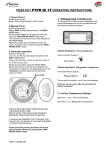
PIZZA DOUGH THAWING
PROVING / RETARDING
CABINET
Environmental Management Policy for Service Manuals and Duets.
Product Support and Installation Contractors
Foster Refrigerator recognises that its activities, products and services can have an adverse impact upon the
environment.
The organisation is committed to implementing systems and controls to manage, reduce and eliminate its adverse
environmental impacts wherever possible, and has formulated an Environmental Policy outlining our core aims. A copy of
the Environmental Policy is available to all contractors and suppliers upon request.
The organisation is committed to working with suppliers and contractors where their activities have the potential to impact
upon the environment. To achieve the aims stated in the Environmental Policy we require that all suppliers and
contractors operate in compliance with the law and are committed to best practice in environmental management.
Product Support and Installation contractors are required to:
1. Ensure that wherever possible waste is removed from the client’s site, where arrangements are in place all waste
should be returned to Foster Refrigerator’s premises. In certain circumstances waste may be disposed of on the
clients site; if permission is given, if the client has arrangements in place for the type of waste.
2. If arranging for the disposal of your waste, handle, store and dispose of it in such a way as to prevent its escape into
the environment, harm to human health, and to ensure the compliance with the environmental law. Guidance is
available from the Environment Agency on how to comply with the waste management ‘duty of care’.
3. The following waste must be stored of separately from other wastes, as they are hazardous to the environment:
refrigerants, polyurethane foam, oils.
4. When arranging for disposal of waste, ensure a waste transfer note or consignment note is completed as appropriate.
Ensure that all waste is correctly described on the waste note and include the appropriate six-digit code from the
European Waste Catalogue. Your waste contractor or Foster can provide further information if necessary.
5.
Ensure that all waste is removed by a registered waste carrier, a carrier in possession of a waste management
licence, or a carrier holding an appropriate exemption. Ensure the person receiving the waste at its ultimate
destination is in receipt of a waste management licence or valid exemption.
6. Handle and store refrigerants in such a way as to prevent their emission to atmosphere, and ensure they are
disposed of safely and in accordance with environmental law.
7. Make arrangements to ensure all staff who handle refrigerants do so at a level of competence consistent with the City
Guilds 2078 Handling Refrigerants qualification or equivalent qualification.
8.
Ensure all liquid substances are securely stored to prevent leaks and spill, and are not disposed of to storm drains,
foul drain, surface water to soil.
DISPOSAL REQUIREMENTS
If not disposed of properly all refrigerators have components that can be harmful to the environment. All old refrigerators must be
disposed of by appropriately registered and licensed waste contractors, and in accordance with national laws and regulations.
Contents
Introduction
1. Specification
2. Installation Instructions
3. operating Instructions
4. Temperature Controllers
LTW15 used from May 2004
LTW 12 used from October 2003
MTW12 used up to October 2003
5. Modification of PTPR RI 1 T from MTW12/MTC11 to LTW12/15 controller
6. Technical Data
7. Wiring Diagram
8. Spare Parts List
9. Cleaning Instructions
INTRODUCTION
The pizza processing is provided in three formats:
Page
1
2
2 to 7
7 to 8
8 to 13
8 to 10
10 to 11
11 to 12
1. Fully automatic process facility incorporating all
three functions.
2. Manual Thaw/store facility.
3. Manual Prove/ Retard process facility.
The control system for each function displays time and
temperature allowing the operator to determine the
status of the process.
12 to 13
The cabinet is designed to accommodate two special
pizza trolleys.( Not supplied as standard).
13
14 to15
16
17
Aluminium bumper bars are fitted to protect the internal
walls.
1
Internal airflow is generated by 3 x 10W motors with
200mm Ø, 31° pitch angle blades.
1. SPECIFICATION
1.1
Pizza Hut Modular Cabinet PTPR-RI-1T
Nomenclature based on - P = Pizza. T = Thaw.
P = Prove. R = Retard. RI = Roll In. 1 = Single section.
T = Top mounted refrigeration system.
Construction.
1.4 Retarding (Refrigeration).
The refrigeration system is a self-contained unit
comprising of air-cooled condensing unit, forced air
evaporator and all ancillary parts and controls. The
equipment is pre-charged with refrigerant and pre-wired
to allow for easy installation on site.
Refrigerant used is R134a.
The evaporator has a large surface area to provide high
humidity during the retard operation.
Refrigerant control is a capillary based system used to
control the correct amount of refrigerant required to meet
the demand of the evaporator.
Constructed of 75mm interlocking panels using
Fosterlock to secure it to its neighbour with the
refrigeration system built onto an independent 100mm
ceiling panel.
The door is a slab type with self-closing rising butt
hinges. Complete with a full height handle and no locks.
Magnetic door gasket and a wiper gasket to the bottom
edge of the door.
The door can be hinged left or right hand as required.
1.5 Proving (Heating).
An electric heater assembly is mounted on the rear face
of the cooling coil which is energised during the prove
process.
As an extra safety feature, a pre-set overheat thermostat
switch is provided should the main control thermostat
fail.
During the Thaw process both cooling and heating are
used to ensure that the air temperature is controlled to
defrost the dough.
External Dimensions: External Width – 1200mm.
External Depth - 965mm. External height – 2206mm.
The cabinets conform to ISO Climate Class 5 (40°c
ambient with 40% RH).
1.2 Electrical Supply
230V, 1 phase, 50Hz.
Fuse rating 13 Amp.
1.3 Control Function.
The cabinet has an on/off switch, electronic digital
temperature controller/ indicator plus function indicator
lights, prove process timer and 24hr timeclock for
automatic prove mode.
The controls are located in a control console mounted
above the door.
1.6 Temperature Ranges.
The cabinet is designed to automatically process Pizza
Dough from a frozen condition (-18°c / -21°c) to a
finished product as below.
Thaw/ Retard Temperature.
1.4 Air Flow.
Air is circulated through the evaporator coil and
discharged through a vented air duct fitted to the rear
wall of the cabinet.
Standard Finish.
Exterior walls.
Rear Walls
Front Wall.
Ceiling.
Door.
Interior Walls & Ceiling.
Base
304 Stainless Steel.
Galvanised Steel.
Stainless Steel 430.
Stainless Steel 304.
Stainless Steel 304.
Smooth Aluminium.
Floorless
+2°c/ +4°c.
Prove Temperature.
+2°c/ +4°c to +28°c/ +32°c.
Retard Temperature.
+28°c/ +32°c to +2°c/ +4°c.
Insulation thickness CFC Free polyurethane foam.
Sides.
75mm
Back
75mm
Front
75mm
Ceiling
100mm
Door
50mm
INSTALLATION INSTRUCTIONS
Installation of these units should be carried out by a competent person and appropriate codes of practise
adhered to thus ensuring safe installation.
REMOVAL OF THE PALLET.
The cabinets are of modular construction with the wall panels and ancillary items delivered with either shrink-wrap or
wood case protective exterior. This exterior should be removed, which after cutting the band will allow all the components
to be removed and then checked for damage before placement in a convenient area for assembly.
There could be more than one crate – so check each one as above.
INSTALLATION OF PANELS AND EQUIPMENT.
The wall panels are numbered and the following instruction is suggested as a method of installation.
Check the drawing of the modular cabinets to obtain the panel numbers.
The ceiling panel is supplied with the refrigeration system / heater assembly pre-fitted ready for installation once the wall
panels are erected.
The cabinets are floorless and therefore require fitting to a clean level floor.
The wall panels are attached to the floor by inserting them into PVC ‘U’ Channel. This needs to be cut and mitred and
should be fitted to the floor prior to installation.
2
Using the cardboard template provided cut the ‘U’ channel to the correct lengths.
The external dimensions of the room are - 1200mm. Wide X - 965mm Deep
It is important that the ‘U’ channel is fixed squarely so that the panels will lock together when inserted.
Cut a 30mm wide section out of the U channel on the non hinge side to allow for the door gasket to fit properly
It is recommended that there should be no more than 3mm tolerance in the floor level as this can effect the correct
location of the locking panels.
Using a spirit level check floor level on all four sides.
If required use shims to take up any anomalies in the floor.
Once you are satisfied with the level the U channel can be rawl-plugged or hilti-nailed into position ensuring it is sealed
with silicone sealer between the floor and the channel to prevent moisture penetration.
Apply ‘mastic sealer’ to the inside of the channel so that when the panels are located there is a vapour seal.
3
ASSEMBLY OF WALL PANELS.
Note: there is no door header panel as this is integral with the ceiling panel.
Fit wall panels and corner panels, these are locked together by means of a camlok operated by a hexagon shaped key
provided. Seal between each wall panel with mastic sealer to provide a vapour seal.
All the panels are locked internally.
After assembly, plug all lock holes with plastic inserts provided.
Lastly seal all joints with silicone sealer provided.
FITTING THE CEILING PANEL.
At the top of the wall panel there is a recess that accepts the ceiling panel.
Apply mastic sealer to this recess so that when the ceiling panel is fitted there is a good vapour seal.
Temporally unscrew the control panel and rest it on top of the ceiling panel.
Lift the ceiling panel with the equipment fitted and lower into the wall panel recess.
4
Fit the stainless steel angle brace that ties the 2 corners together using 2x M6 button headed socket screws
ensuring that they are pulled square.
Make sure that the ceiling panel finishes flush with the corner panel.
This detail shows the notch in the U channel with the corner panel in place.
Therefor allowing the gasket to seal against the panel.
5
Refit the control panel.
The control console housing the thermostat, timers and the function indicator lights is fitted to the unit compartment side
panels.
Fit the internal aluminium bumper bars to the side walls.
Fit the air duct to the rear wall of the cabinet, through the holes on each side, by aligning its bumper bars to the side wall
bumper bars.
FITTING THE DOOR
Fit the door hinge to the panel and ensure that the inserts are fitted correctly for the door hinging.
Fit the door on to the hinges and check that it hangs squarely to the room.
The door can be removed by opening to 90°and lifting off the hinge, for re-fitting
reverse the process.
6
After hanging the door ensure that there is a good gasket seal around the doorframe.
Also ensure that the door wiper gasket, fitted to the bottom of the door, seals to the floor when closed.
If necessary, the door can be lifted slightly using the adjustment on the hinges.
3. OPERATING INSTRUCTIONS.
Manual Retard.
Switch on the power.
Select ‘MAN’ by depressing the top of the MAN / AUTO switch.
Manual Prove.
Switch on the power.
Select ‘MAN’ by depressing the top of the MAN / AUTO switch.
Set the ‘Prove Timer’ to the required prove time.
Press the ‘MAN PROVE START’ switch.
The machine will now prove for the time selected on the ‘Prove Timer’.
When the process time is finished an alarm will sound and the machine automatically goes into retard mode.
The alarm can be silenced using the ‘MAN / PROVE STOP’ switch.
Automatic operation.
Switch on the power.
Select the ‘AUTO’ by depressing the bottom of the ‘MAN / AUTO’ switch.
Ensure that the time of day on the time clock is set to the correct time.
Set the prove duration using the ‘Prove Timer’.
7
Time Of Day
NOTE
Ensure pin is positioned in
the central position.
Set the time that you wish the prove sequence to commence by ‘pulling out’ the appropriate pin on the ‘Timeclock’ as
shown below (Prove Start time shown is 19:00, Normal start time for Pizza Hut is 07:00).
CARE SHOULD BE TAKEN WHEN SELECTING THE PROVE START TIME.
PROVE START TIME SHOULD BE PRODUCT REQUIRED TIME LESS PROVE DURATION.
IT SHOULD BE ENSURED THAT THE ONLY PIN PULLED OUT AS SHOWN IS THE ONE REQUIRED TO START THE
PROCESS.
At the end of the process the alarm will sound and should be silenced by pressing the ‘MAN PROVE STOP’ button.
4. TEMPERATURE CONTROLLERS
LTW 15 Controller used from May 2004
It has 2 relay outputs that can be programmed with individual set points and ranges. It uses a three-wire probe.
It is strongly advised that before adjusting any Service Parameters a thorough understanding of the following
instructions should be obtained.
Out1
lae
Out2
set
1
L2
3
2
Check set point 1. Prove Temperature.
Check set point of output 1. Press button 1 “set”
Check set point 2. Refrigeration Temperature.
.Press button 4 “L2”. Not accessible as locked out (see parameter LOC).
The set point on buttons 1 and 2 can not be altered.
Exit from set up occurs after 10 seconds if no button is pressed.
8
4
Factory Temperature Settings.
Set Point 1. +32°c. Prove Temperature.
Set Point 2. +2°c. Refrigeration Temperature.
LTW 15 Controller Set Up.
The parameters are accessed by pressing the following keys in succession
them pressed for 3 seconds.
+ “set” +
and keeping
Access to the parameters has been achieved with the first parameter SCL displayed.
The parameters are the same as for the MTW 12 controller shown in the table below.
To pass from one parameter to the next press either the
or
key.
To display the value press “set”.
To change the value press “set” +
to increase, or “set” +
to decrease.
Press button “L2” to exit from set up.
Alarms. OR is displayed in the event of a probe fault.
Controller Parameters
The parameters should not be changed from those listed without prior consent from Foster Refrigerator.
Note: Ensure ‘SCL’ is set at ‘C01’ and not ‘C.01’. ‘C01’ gives a singular reading, ‘C.01’ gives a reading with a
decimal point which is not required by Pizza Hut.
When changing parameter ‘2SP’ to ‘2’ it is important that parameter ‘SPL’ is left at ‘00’ until the change to’2SP’ is
made, once the ‘2SP’ has been set at ‘2’ proceed to change ‘SPL’ to 32.
Failure to follow the instruction will mean that ‘2SP’ will not be adjustable and will remain at ‘32’.
LTW15 / LTW 12
PARAMETER
Reading Scale
Min. Temp. Set Point
Max. Temp. Set Point
Effective Temp. Set Point Channel 1
Control Type Channel 1
Change Over Hysteresis Channel1
Proportional Band Channel 1
Integral Action Time Channel 1
Derivative Action Time Channel 1
Reset of Integral Action Referred to 'Pb1'
Cycle Time Channel 1
Channel 1 Status with Faulty Sensor
Control Mode Channel 2
Effective Temp. Set Point Channel 2
Temperature Differential Set 2 to Set 1
Mode of Operation Output Channels
Control Type Channel 2
Change Over Hysteresis Channel 2
Proportional Band Channel 2
Integral Action Time Channel 2
Derivative Action Time Channel 2
Reset of Integral Action Referred to 'Pb2'
Cycle Time Channel 2
Channel 2 Status with Faulty Sensor
Lock Off Key' L2'
Display Slowdown
Sensor Correction
Peripheral Address
9
MNEMONIC
SCL
SPL
SPH
1SP
1Y
1HY
1PB
1IT
1DT
1AR
1CT
1PF
2CM
2SP
2DF
20M
2Y
2HY
2PB
2IT
2DT
2AR
2CT
2PF
LOC
SIM
OS1
ADR
PTPR RI 1T
C01
32
32
32
HY
-4
-50
350
50
90
10
OFF
AbS
2
0
FrE
HY
2
50
350
50
90
10
OFF
YES
0
0
1
Electrical Connections for the LTW 15 Controller.
0/4 – 20mA
GND
I
+12Vdc
9
Data I/O
IN
OUT 1
8 (3)A
10
11
V-
V+
OUT 2
8 (3) A
12 V ~ /
1
2
3
4
5
7
8
230 v~
LTW12 controller fitted from October 2003.
It has 2 relay outputs that can be programmed with individual set points and ranges.
It uses a three-wire probe.
It is strongly advised that before adjusting any Service Parameters a thorough understanding of the following
instructions should be obtained.
1
3
2
4
When power is applied to the unit three bars will be displayed for approximately three seconds for the controller to
complete the internal self test function.
Check set point 1SP. Check set point of out 1.
Press button 1
Check set point 2SP. Check output of out 2.
Press button 2
L2. Not accessible as locked out (see parameter LOC).
The set point on buttons 1 and 2 can not be altered.
10
Controller Set Up.
Access to the controller is achieved by pressing in sequence: –
+
+
And holding for a period of 4 seconds.
It is possible to scroll through the parameters by pressing
or
The value of a selected parameter is checked by pressing
and may be altered by pressing
or
Press the button L2 to exit and save the changes made.
Exit from set up occurs after 30 seconds if no button is pressed with non-of the changes being saved.
Controller Parameters are the same as the LTW15 see table on page 9.
MTW12 controller fitted up to October 2003.
It has 2 relay outputs that can be programmed with individual set points and ranges.
It uses a three-wire probe.
It is strongly advised that before adjusting any Service Parameters a thorough understanding of the following
instructions should be obtained.
Check set point 1. Check set point of output 1.
Press button 1
Increase set point
Press and hold button 1
Press button 3
until required temperature is displayed.
Decrease set point
Press and hold button 1
Press button 4
until required temperature is displayed.
Check set point 2. Check output of output 2.
Press button 2
L2
Set points for L1 and L2 are fixed and cannot be altered unless the parameters are changed.
Controller Set Up.
11
Access to the controller is achieved by pressing in sequence: –
+
+
And holding in keys for a period of 4 seconds.
It is possible to scroll through the parameters by pressing
or
The value of a selected parameter is checked by pressing
and may be altered by pressing
or
Exit from set up occurs after 10 seconds if no button is pressed.
Factory Set Parameters.
No
PARAMETER
1
Min set point (°c)
2
Max set point (°c)
3
Temp hysteresis (°K)
On/Off cycle time out time
4
Relay state on probe fail
5
6
Min set point (°c)
7
Max set point (°c)
8
Temp hysteresis (°K)
On/Off cycle time out time
9
Relay state on probe fail
10
DO NOT CHANGE
11
Mnemonics
1Lo
1hi
1hy
1ct
1PF
2Lo
2hi
2hy
2ct
2PF
dPS
PTPR RI 1 T
+32
+32
-4
0
0
+2
+2
+2
0
1
SET POINT OUT
1
SET POINT OUT
2
+32
+1
5. MODIFICATION OF PTPR RI 1 T FROM - MTW12/MTC11 TO LTW12/15 CONTROLLER
This modification must be carried out using the following applicable Wiring Diagrams, on pages 13 and 14, and after
careful studyController MTW12 - 00 – 744553 - 00-03
Controller LTW12 - 00 - 744553 – 00-04
The Controller LTW 12 is configured differently and requires just one electrical supply to the contacts of the internal
relays.
The Relay coil of R4 and the contacts of R4 & R6 need to be rewired so that both sets of contacts are after the outputs of
the controller rather than before the inputs. The procedure below should be followed.
PTPR Controller change from MTW12 to LTW 12/15
1) Remove Cable Number 16 from the Manual /Auto switch and cables connected to Terminal 1 of the existing
controller(MTW12)and join together using an insulated but t connector
2) Remove link from Relay 4 (R4) between terminal numbers 2 & 8
3) Remove link from R 4 terminal 6 and R1 terminal 3
4) Disconnect cable marked 33 from R4 terminal 6 and connect to R1 terminal 3
5) Disconnect cable marked 23 from R6 terminal 4 and connect to R4 terminal 8
12
6) Connect link from R4 terminal 6 to R6 terminal 4
7) Remove cables marked 25 on 24 Hour timer (T1) terminal 5 and connect to terminal 4 of the replacement
controller (LTW12/15)
8) Connect a cable from terminal 11 of the Omron timer (T2) to R4 terminal 1
9) Remove link from R4 terminal and Transformer (cable 31) .Connect other cable marked 31 to transformer
10) Connect a new cable from terminal 1 of new controller (LTW12/15)to cable 31 on Man/Auto switch
11) Connect a link from R4 terminal 4 to R6 terminal 8
12) Disconnect cable number 23 from MTW12 controller terminal 2 and connect to terminal 2 of the new
controller (LTW12/15)
On completion set the parameters as described on pages 8 and 9.
6. Technical Data
Model
Ref
Ref
Charge
Volts
Phase
Hz
PTPR RI 1T
R134A
700 grms
230
1
50
13
Power
Absorbed
Retard
823w
Power
Absorbed
Prove
1970w
Run
Amps
Retard
4.4
Run
Amps
Prove
8.5
7. Wiring diagrams for models with LTW15 and LTW12 Controller
Wiring Diagram For models with MTW12 Controller
8.Spare Parts List
ITEM
Compressor
Condenser
Condenser Fan
Condenser Filter
Condenser Filter
Drier R134A
Vaporiser Tray
Vaporiser Heater
Prove Heaters
Drain Line Heater
Evaporator
Evaporator Fan
Capillary 3M x 064
On /Off switch
Time Clock
Process Timer
Timer Mounting Bracket
11 Pin Base
Alarm
Relay
Relay Clip
8 Pin Relay
8 Pin Relay Base
Switch M/On
Switch M/On
MAN/AUTO Switch
LTW15 Controller
LTW 12 Controller
MTW 12 Controller
Probe
Transformer
Safety Thermostat
Circuit Breaker
Circuit Breaker
Door
Door
Door Gasket
Hinge
Door Handle
Door Handle Inner Release
Wiper Gasket
DESCRIPTION
CAJ 4492Y
LUVA 194
Stainless Steel
Polyfoam
With Heater
140W
915W
1.5w 240v
Evap Coil E3/8-7-4-7-39 Coated
10W. 240 volt.
Available in 5m lengths
Illuminated
24 hr Mil72 Ae Stuzh
Omron H2c-S
For above
For Above
Buzzer Pieco 12s 32400 AC/DC
30amp 240v AC G7L1AT
For Above
10amp 8 pin Mk2ps 230v
For Above
Illuminated Amber
Illuminated Clear
2 Position
From May 2004
From October 2003
Up to October 2003
For All Controllers
Tr 240v/12 vt
65 / 150°c
10 Amp
6 Amp
R/Hand
L/Hand
930 x 1764mm Magnetic
Fermod 481
Fermod 921
Fermod 921
16
PART NUMBER
15422102
15431180
15470027
01-232048-01
01-232050-01
15480908
16020373
15240023
15843321
15240316
15463046
00-599687
16010664
15243565
00-554018
15452534
15452535
15490415
15244985
15490420
15490421
15490414
15490416
00-554017
00-554016
15243601
16240057
16240045
00-599555
16240555
15246111
00-599554
15242488
15242487
16050965
16150965
15211782
15230550
15230247
15230359
16040015
9. Cleaning Instructions.
N.B. Before internal cleaning, switch off the unit.
Condenser Filter
Lift the filter sufficiently to clear the bottom of the opening, ease it forward from the housing and gently slide it out.
Use a soft brush or vacuum cleaner to remove any dust or fluff and wash in a solution of mild soapy water.
Once it has dried completely replace into the housing.
Cabinet.
Cared for correctly, stainless steel has the ability to resist corrosion and pitting for many years.
The following weekly cleaning regime is recommended.
a. Exterior: Use a proprietary stainless steel cleaner following the manufacturer instructions.
b. Interior: Wash with soapy water, rinse and dry thoroughly.
Gaskets.
These should be inspected on a regular basis and replaced if damaged.
To clean, wipe with a damp soapy cloth followed by a clean damp cloth and finally thoroughly dry before closing the door.
WARNING.
High alkaline cleaning agent or those containing bleaches, acids and chlorine’s are very harmful to stainless steel.
Corrosion and pitting may result from their accidental or deliberate application. If any of these liquids should come into
contact with the unit during general kitchen cleaning, wipe down the affected area immediately with clean water and rub
dry.
Never use wire wool or scouring powders on stainless steel or aluminium surfaces.
After cleaning allow the unit to reach its normal operating temperature before reloading with product.
During usage all spills should be wiped clean immediately.
17
18
Foster European Operations
France
Foster Refrigerator France SA
Tel: (33) 01 34 30 22 22. Fax: (33) 01 30 37 68 74.
Email: [email protected]
Germany
Foster Refrigerator Gmbh,
Tel: (49) 2333 839375. Fax (49) 2333 839377.
Email: [email protected]
Foster Refrigerator
Oldmedow Road
Kings Lynn
Norfolk
PE30 4JU
Tel: 01553 691122
Fax: 01553 691447
Website: www.fosterrefrigerator.co.uk
Email: [email protected]
a Division of ‘ITW (UK) Ltd’
PTPRRI1T/OP/04/05 Rev 5
19