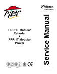
1
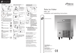
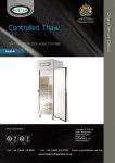
CONTROLLED
THAW CABINET
WITH
SURF NAVIGATION
CT70-B
ISO 14001
ISO 9001
Contents
Environmental Management Policy
Disposal Requirements
Cabinet description
Controller Operation
Alarms and Warnings
Service Settings
Settings and Parameters
Probe temperature resistance values
Wiring Diagram
1
1
1 to 2
2
3
3 to 4
4 to 7
7
8
Environmental Management Policy for Service Manuals and Duets.
Product Support and Installation Contractors
Foster Refrigerator recognises that its activities, products and services can have an adverse impact upon the
environment.
The organisation is committed to implementing systems and controls to manage, reduce and eliminate its adverse
environmental impacts wherever possible, and has formulated an Environmental Policy outlining our core aims. A copy
of the Environmental Policy is available to all contractors and suppliers upon request.
The organisation is committed to working with suppliers and contractors where their activities have the potential to
impact upon the environment. To achieve the aims stated in the Environmental Policy we require that all suppliers and
contractors operate in compliance with the law and are committed to best practice in environmental management.
Product Support and Installation contractors are required to:
1. Ensure that wherever possible waste is removed from the client’s site, where arrangements are in place all waste
should be returned to Foster Refrigerator’s premises. In certain circumstances waste may be disposed of on the
clients site; if permission is given, if the client has arrangements in place for the type of waste.
2. If arranging for the disposal of your waste, handle, store and dispose of it in such a way as to prevent its escape
into the environment, harm to human health, and to ensure the compliance with the environmental law. Guidance
is available from the Environment Agency on how to comply with the waste management ‘duty of care’.
3. The following waste must be stored of separately from other wastes, as they are hazardous to the environment:
refrigerants, polyurethane foam, oils.
4. When arranging for disposal of waste, ensure a waste transfer note or consignment note is completed as
appropriate. Ensure that all waste is correctly described on the waste note and include the appropriate six-digit
code from the European Waste Catalogue. Your waste contractor or Foster can provide further information if
necessary.
5.
Ensure that all waste is removed by a registered waste carrier, a carrier in possession of a waste management
licence, or a carrier holding an appropriate exemption. Ensure the person receiving the waste at its ultimate
destination is in receipt of a waste management licence or valid exemption.
6. Handle and store refrigerants in such a way as to prevent their emission to atmosphere, and ensure they are
disposed of safely and in accordance with environmental law.
7. Make arrangements to ensure all staff who handle refrigerants do so at a level of competence consistent with the
City Guilds 2078 Handling Refrigerants qualification or equivalent qualification.
8.
Ensure all liquid substances are securely stored to prevent leaks and spill, and are not disposed of to storm
drains, foul drain, surface water to soil.
DISPOSAL REQUIREMENTS
If not disposed of properly all refrigerators have components that can be harmful to the environment. All old
refrigerators must be disposed of by appropriately registered and licensed waste contractors, and in accordance with
national laws and regulations.
1
Cabinet description
304 Stainless Steel interior and exterior finish
The cabinet provides a 70kgs capacity
Thaw food safely from -18/-21ºC to +1/+4ºC
Thaw cycle takes approximately 7 hours based on maximum capacity and 25mm product thickness (thicker products
will take longer)
Overnight storage hold facility, so thawed food is ready for use when you want to use it
Stainless steel dished base with drain facility for easy cleaning
Thaw cabinets alternate between circulating gentle heat and refrigeration, via special air ducting and fans, ensuring an
even, speedy and safe thaw
Operation
Upon starting the selected Thaw cycle the controller will increase the internal air temperature in a controlled manner
throughout the time period determined by the Phase 1 time and temperature parameters e.g. programme 1= default
time setting 5hours 30 minutes, default temperature setting +10ºC. On reaching the cabinet air temperature of +10ºC
the controller will cycle between heat and refrigeration relative to the phase 1 parameter settings.
This will be followed by the second timed period, Phase 2, which will lower the cabinet temperature to avoid any
surface damage to the product. Default time setting 1 hour, default temperature setting + 7 ºC. On reaching the cabinet
air temperature of +7ºC the controller will cycle between heat and refrigeration relative to the phase 2 parameter
settings. NOTE: This phase is not used by KFC, see separate parameter list.
Finally on completion of the phase 2 time period the controller will enter an indefinite period holding the cabinet
temperature at + 1 ºC to + 4 ºC. Refrigeration only.
Double Thaw Phase Cycle
Phase 2
Phase 1
Storage
P1 Set Point
P1 Hysteresis
Temperature
P2 Set Point
P2 Hysteresis
Storage Hysteresis
Storage Set Point
Start Temperature
Time
Single Thaw Phase Cycle KFC Only
Phase 1
Phase 2
P1 Set Point
Temperature
P1Hysteresis
Storage Hysteresis
Storage Set Point
Start Temperature
Time
2
Storage
Thaw Operators Guide with SURF Navigation Control
STORAGE
2 ºC
Standard Operation
SYSTEM TEST
SIMPLE +
When mains electrical power is first applied to the controller it will carry out a self-test function,
for approximately 3 seconds. During this period the display will show.
Software Revision 1b
By LAE ELECTRONIC
On completion of the self test, the controller will revert to the last chill program that was run
(STORAGE, Programme 1, Programme 2, Programme 3).
STORAGE
STORAGE
STORAGE
STORAGE
PROGRAMME 1
PROGRAMME1
PROGRAMME 1
PROGRAMME 1
PROGRAMME 2
PROGRAMME 2
PROGRAMME 2
PROGRAMME 2
PROGRAMME 3
PROGRAMME 3
PROGRAMME 2
PROGRAMME 3
TURNTO SELECT- PRESS TO START
TURN TO SELECT- PRESS TO START
TURN TO SELECT- PRESS TO START
TURN TO SELECT- PRESS TO START
The examples show the programmes available. To change the program, rotate the dial either clockwise or
anticlockwise to select the program you require.
For example select Programme 1and press the dial. The programme starts with the screen second from the left being
displayed for one minute. During this period the time can be adjusted by a limited amount if required, rotate the dial
clockwise to increase or anti clockwise to decrease.
NOTE: For KFC models it is not recommended to alter the time.
After one minute the display will change to show the screen in the middle showing the time remaining plus the cabinet
temperature displayed in the left hand corner of the display.
With one hour remaining on the programme the display will change to show the screen second from the right
displaying time and temperature.
On completion of the programme the display will change to display the screen on the right indicating temperature has
been achieved and will hold the temperature at plus 2ºC until the dial is pressed for 2 seconds terminating the
programme.
PROGRAMME 1
STORAGE
PROGRAM 1
-10°C
PROGRAMME 1
2°C
5: 30
PROGRAMME 1
PROGRAMME 1
59: 59
2 ºC
2°C
5: 30
PROGRAM 2
PROGRAM3
TURN TO SELECT- PRESS TO START
PHASE 1 PHASE 2
HOLD
PHASE 1
PHASE 2
HOLD
PHASE 2
HOLD
HOLD
TURN TO Adj. – PRESS TO STOP
If a programme is not run for 20 minutes the display will change to show the controller in ‘sleep’ mode.
The ‘sleep’ mode will be maintained until the dial is pressed, rotated or the door opened when
the display will revert to showing the ‘User Menu’.
Door Open Alarm
If the door is opened during a programme or storage phase the evaporator fan will stop and screen will change, see
below.
3
PROGRAMME 1
After 1 minute the condensing unit will stop, if the door is left open for more than 5 minutes the
alarm will sound. The alarm can be cancelled by closing the door
5: 30
PHASE 1
PHASE 2
HOLD
Door Open
Defrost.
Defrosting is only activated during the Storage mode.
The interval between defrosts is 6 hours, this means that over a twenty four hour period, whilst in the storage mode, it
will defrost 4 times.
Alarms and Warning
High Temperature Alarm
The alarm will sound and high temperature alarm will be displayed if the storage temperature
rises too high for to long.
Causes for this alarm could be:
Is the airflow restricted? Does the condenser filter require cleaning?
Is the evaporator fan running?
If the problem persists call your Foster Authorised Service Company.
Power Fail:
The alarm will sound in the event of power failure to the machine.
If the power is off for less than five minutes the unit will re-start on the resumption of the power
supply without affecting the selected cycle.
If the power is off for longer than five minutes the controller will enter the storage mode on the
resumption of the power.
To re-start press and release the dial, the screen will return to the hold screen. Press and hold
the dial for two seconds the display returns to the program selection.
Air Probe:
If this alarm occurs the programme will stop with the screen displayed left. The alarm will
sound and can be cancelled by pressing and releasing the dial or it will stop after a set period
but resound again after a pre-set time. The controller will automatically enter the storage
phase until the cycle is stopped but it will not be possible to start further cycles until your
Foster Authorised Service Company has rectified the fault.
HIGH TEMPERATURE
POWER FAILURE
AIR PROBE
SERVICE SETTINGS
Service settings access
Whilst in the program selection screen press and hold the dial for 2 seconds, the information screen will be displayed
continue pressing the dial for a further 2 seconds to display the ‘SERVICE MENU’. LANGUAGE will be highlighted.
SERVICE
LANGUAGE
ENG
DIAGNOSTICS
1-COMP
FOOTPRINT
CODE
0
Press 2 seconds for Exit
Changing Text Language.
With LANGUAGE highlighted, press and release the dial, ‘ENG’ (English) will be highlighted.
Note: English is the only language available for this controller.
4
Settings and Parameters
Passcode.
Rotate the dial until you reach ‘PASSCODE’, below left, press and release the dial to highlight the code, below right.
Rotate the dial until you reach the code ‘131’. Once achieved press and release the dial to acknowledge.
SERVICE
SERVICE
LANGUAGE
LANGUAGE
ENG
DIAGNOSTICS
ENG
DIAGNOSTICS
1-COMP
1-COMP
FOOTPRINT
FOOTPRINT
CODE
CODE
0
131
Press 2 seconds for Exit
Press 2 seconds for Exit
Profiles.
You are now in the program profiles. The controller has 5 operating programs – STORAGE, Program 1, Program 2,
Program 3, Program 4.
These programs are all available depending upon which of the profiles are selected, see below.
Storage
SIMPLE
X
9
SIMPLE +
STANDARD
X
9
STANDARD +
X = DISABLED
Program 1
9
9
9
9
9 = ENABLED
Program 2
9
9
9
9
Program 3
9
9
9
9
Program 4
X
X
9
9
To change the profile, rotate the dial to select program, press and release the dial to accept the change. The 3
chevrons in the box opposite the selected program confirm the change.
The default operating profile is ‘STANDARD+’.
The table identifies which programs are available from the profile selected.
SERVICE
STANDARD
STANDARD +
EXPRESS
EXPRESS +
THAW
THAW +
Press 2 seconds for Exit
Parameter Access.
From the profile screen once the selection has been made press and release the dial to access the parameter list. The
screen will display the parameters as shown in the screen below left. To access the system parameters rotate the dial
anticlockwise see below right.
5
STANDARD +
STANDARD +
STORAGE
AUTOMATIC THAW
MANUAL PROVE 1
SYSTEM
MANUAL PROVE 2
MANUAL PROVE 3
ADPR 1
MANUAL THAW 1
MANUAL THAW 2
MANUAL THAW 3
Press 2 seconds for Exit
Press 2 seconds for Exit
Selection is made by pressing and releasing the dial.
The table below contains the complete parameter list and includes the selectable range and default values.
PARAMETERS
PARAMETER
PO1
PO2
PO3
PO4
PO5
PO6
PO7
PO8
PO9
P10
P11
P12
P13
P14
P15
P16
P17
P18
P19
P20
P21
P22
P23
P24
P25
P26
P27
P28
P29
P30
P31
P32
P33
P34
P35
P36
DESCRIPTION
STORAGE
Air Temperature
PROGRAM 1
P1 Temperature Default
P1 Time Default
P1 Time Minimum
P1 Time Maximum
P2 Temperature Default
P2 Time Default
P2 Time Minimum
P2 Time Maximum
PROGRAM 2
P1 Temperature Default
P1 Time Default
P1 Time Minimum
P1 Time Maximum
P2 Temperature Default
P2 Time Default
P2 Time Minimum
P2 Time Maximum
PROGRAM 3
P1 Temperature Default
P1 Time Default
P1 Time Minimum
P1 Time Maximum
P2 Temperature Default
P2 Time Default
P2 Time Minimum
P2 Time Maximum
PROGRAM 4
P1 Temperature Default
P1 Time Default
P1 Time Minimum
P1 Time Maximum
P2 Temperature Default
P2 Time Default
P2 Time Minimum
P2 Time Maximum
SYSTEM
P1 Heat Hysteresis
P2 Heat Hysteresis
Storage Hysteresis
VALUE
MINIMUM
MAXIMUM
STANDARD
DEFAULT
SETTINGS
KFC
°C
-25
25
2
2
°C
MINUTES
MINUTES
MINUTES
°C
MINUTES
MINUTES
MINUTES
0
PO4
0
0
0
PO8
0
0
45
PO5
900
900
45
PO9
900
900
8
270
60
600
6
60
60
60
8
330
330
330
6
0
0
0
°C
MINUTES
MINUTES
MINUTES
°C
MINUTES
MINUTES
MINUTES
0
P12
0
0
0
P16
0
0
45
P13
900
900
45
P17
900
900
8
330
60
600
6
60
60
60
8
420
420
420
6
0
0
0
°C
MINUTES
MINUTES
MINUTES
°C
MINUTES
MINUTES
MINUTES
0
P20
0
0
0
P24
0
0
45
P21
900
900
45
P25
900
900
8
540
60
60
6
60
60
60
8
540
540
540
6
0
0
0
°C
MINUTES
MINUTES
MINUTES
°C
MINUTES
MINUTES
MINUTES
0
P28
0
0
0
P32
0
0
45
P29
900
900
45
P33
900
900
9
720
60
900
6
0
60
60
9
0
0
0
6
0
0
0
°K
°K
°K
-20
-20
2
-2
-2
20
-2
-2
3
-2
-2
3
6
P37
P38
P39
P40
P41
P42
P43
P44
P45
P46
P47
P48
P49
P50
P51
P52
P53
P54
P55
P56
P57
P58
P59
P60
Short Cycle Delay
Thaw Fan OP.
Storage Fan OP.
Defrost Type
Defrost Per Day
Defrost End Time
Defrost End Temperature
Drain Time
Fan Delay Temperature
Duty Cycle
Compressor Rest Time
Door Switch 1
Door Stop
Door Alarm Delay
High Temperature Alarm
High Alarm Delay
Alarm Time
Alarm Repeat Interval
Alarm Buzzer
Evaporator Probe Enable
Air Probe Offset
Evaporator Probe Offset
Contrast
Address
MINUTES
FUNCTION
FUNCTION
FUNCTION
INTEGER
MINUTES
°C
MINUTES
°C
10x%
MINUTES
FUNCTION
MINUTES
MINUTES
°K
MINUTES
SECONDS
MINUTES
FUNCTION
FUNCTION
°K
°K
INTEGER
INTEGER
0
30
CYCLE/AUTO/ON
CYCLE/AUTO/ON
OFF/ELE/GAS
0
24
1
60
0
50
0
30
-15
15
0
10
0
30
NO
YES
0
30
0
30
0
50
0
120
0
120
0
480
NO
YES
NO
YES
-15
15
-15
15
0
100
1
255
2
ON
AUTO
OFF
4
20
20
1
5
6
1
YES
1
5
10
30
20
0
NO
YES
0
0
50
1
2
ON
ON
OFF
4
20
20
1
5
6
1
YES
1
5
10
30
20
0
NO
YES
0
0
50
1
NOTE: On early version of this model the P39 ‘Storage Fan OP’ was set to ‘AUTO’ the setting should be changed to
‘ON’.
Probes
Air and Evaporator Probes
The air and evaporator probes, type 2K NTC, are the same and are identified as T1 Air Probe and T2 Evaporator
Probe. These are the thermistor type and are fully enclosed to make it completely waterproof and resilient to
temperature variation within the limits of rapid cycling. The probe is capable of measuring temperature in excess of 30°C and 50°C with 1°K accuracy at 1°C and no more than 2°K at the upper and lower temperature ranges.
Probe temperature resistance values
°C
K ohm
°C
K ohm
-40
44.657
-5
7.198
-35
33.505
0
5.716
-30
25.388
5
4.571
-25
19.402
10
3.682
-20
14.961
15
2.987
-15
11.644
20
2.437
-10
8.133
25
2
°C
30
35
40
45
50
55
60
K ohm
1.651
1.371
1.143
0.958
0.807
0.683
0.582
7
°C
65
70
75
80
85
90
95
K ohm
0.497
0.426
0.367
0.318
0.276
0.24
0.21
°C
100
105
110
115
120
125
K ohm
0.189
0.166
0.142
0.125
0.111
0.099
CT70B Wiring Diagram
8
9
10
Foster European Operations
France
Foster Refrigerator France SA
Tel: (33) 01 34 30 22 22. Fax: (33) 01 30 37 68 74.
Email: [email protected]
Germany
Foster Refrigerator Gmbh,
Tel: (49) 781 990 7840. Fax (49) 781 990 7844.
Email: [email protected]
Foster Refrigerator
Oldmedow Road
Kings Lynn
Norfolk
PE30 4JU
Tel: 01553 691122
Fax: 01553 691447
Website: www.fosterrefrigerator.co.uk
Email: [email protected]
a Division of ‘ITW (UK) Ltd’
CT70B/SM 02/08 Rev 1.
11