1
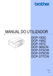
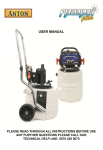
Pneumatic
Heat Press
Revision: 3
Operators Manual
Wader Labelling Systems Ltd
©2003
Location and Set-up.
The press must be located near to a filtered air supply and a 240v singlephase mains supply.
Ensure that the machine is fixed on a solid bench / table away from dust and
sunlight.
Connect the foot switch to the plug on the side of the press.
The air fitting on the back of the heat press is a 1/8" female thread coupling;
air intake pressure must be no more than 100PSI.
Operation
Before switching on press ensure that air is connected to the machine.
Switch press on using the black button on the side of the machine.
When you switch on or reset the press, the control unit will recalculate the
current temperature of the heat plate.
The controller will disable operation of the sealing cycle until the temperature
is correct.
When the light on the controller is under the lettering OUT2 is illuminated, this
indicates that the pre-programmed temperature that is acceptable to seal
down labels has been reached.
The second light under OUT1 indicates if power is been applied to the
element (i.e. element is heating up).
With the air supply set at approx. 80 psi, the temperature ok at about 204'C
set the timer unit to the desired dwell time, place the article to be marked on
the silicone pad along with the label / transfer, remove your hands away
from the sealing pad area at all times and actuate the foot switch and keep
pressed down until the heat plate touches the garment / pad the timer will
now actuate (operator may let go of the foot switch) and keep the sealing
cycle going for the predetermined time.
Once the dwell time has elapsed the platen will raise automatically.
Controls
The temperature controller fitted to this machine is microprocessor based
with a large bright 3-digit display.
Internal programming parameters are carried out at the factory but the
operator may change the pre-set temperature and the temperature disable
function if required.
Temperature Change.
1)
2)
3)
To change the pre-set temperature (temp that the press is constantly
running at) press and hold the top left thermometer button.
The currently stored temperature will now be displayed.
Whilst holding the button press the arrow keys on the right hand side of
the controller until required temperature is reached.
Release all the buttons and the temperature will be stored.
Temp / Operation Disable Function.
This function allows the operator to define a temperature that the machine
will become inoperative.
Example: - if the labels you are applying must be sealed down at a
temperature no less than 195C the control unit will disable the foot switch if
the temperature is below this figure so that the operator cannot actuate the
machine until the correct temp has been reached.
1)
Press and hold the L2 button.
This will display the current setting.
2)
Whilst holding this key press the arrow buttons to set the required
temp.
Please note that this setting must be lower than the temperature
setting or the machine will always be disabled!
Air Pressure
The air pressure that the machine operates at can be adjusted by turning the
large black knob on the left-hand side of the machine.
The knob pulls out slightly and can be turned to increase / decrease
pressure, once the desired pressure has been reached press the knob back
in to lock it into position.
If the machine is used on low air pressures tape may not seal correctly.
We recommend a setting of 80 PSI.
Problems
Press inoperative (will not switch on)
-
Fuse blown check internal DIN
mounted fuse.
Platen cover jammed up & not
making contact with safety
switches.
Heat plate not getting hot
-
Open circuit element.
Probe failure the control unit is
programmed to shut off power
In the case of probe failure.
Lack of pressure
.-
Check air supply and regulator
on side of machine.
Stop Circuit / Emergency stop
To switch the machines off simply press the large emergency stop button on
the front.
The power supply circuit on this machine runs through an isolating circuit,
when the operator depresses the ON button a relay latches and holds power
throughout the machine, a split second interrupt in the power supply will
cause the relay to de-energise thus completely isolating positive and
negative circuits in the machine.
To reset the machine or switch it back on simply press the ON button.
The platen cover and emergency stop switches are wired into the same
circuit.
STOP Button
Platen Cover
(CHECK OPERATION PERIODICALLY)
The platen cover fitted to the press is spring loaded with three independent switches to
detect any obstructions when the heat plate comes down.
The three switches press against the top of the cover any movement against the cover
making it lift more than approx. 2mm will release the switch thus resulting in the power
supply circuit to be broken and isolated.
THE HEAD OF THE MACHINE WILL RETURN TO THE START POSITION.
Press the ON button to restart the machine.
The height from the top heat plate to depress the switch roller is 35mm; the switches can
be independently adjusted via the slot on the switch mounting plate.
Please note that if the switches are not making good contact with the platen cover false
readings may occur, therefor all switches must be adjusted correctly.
Adjust the switches for platen cover emergency stop. A m3 torx screw
located at the side of the switch secures the switch after the desired height
has been determined by lifting the cover a suitable amount before power is
cut off.
Components Identification
Timer Unit & Pressure Regulator
Solenoid Valve
Isolating Relay
Emy. Stop / Cylinder / Temp Control
Parts list For Revision 3 Machines
MTW-12
1752 H
260-662
Norg-rev:3
A30-norg
Switches
A01-1
A02-1
A03-1
A05-3
Electronics
A06
A08
A09-1
A10
A11 x ?
A27
A36
Pneumatics
A13-norg
A14-norg
A17
A31-norg
Heat Plate
GSW 14
A18
GSW 22
A24 (state size) A25-3-norg
A32
A33
A34
A35
-
A37
A38
A39
-
Microprocessor control unit with digital display.
Timer unit.
6 Digit counter with reset 240VAC
Solenoid valve Nug 40 inc. sol
Valve cable.
Emergency stop (body & contact)
Mains Switch BLACK
Foot switch (imo type)
Safety Guard micro switches V3 3 off
Transformer for MTW12 Control Unit
Power light
Timer connector 8 PIN.
Cable gland nylon
DIN rail connectors various.
Power on isolating relay
Foot Switch connector complete
Pressure indicator PSI / Bar
Pressure Regulator Valve
Air tubing 6MM O/D 3mtr length
63mm X 150mm cylinder
Element 500W @ 240VAC.
Silicone pressure pad.
RTD probe 2 wire.
PTFE for heat plate.
Instruction Booklet.
Upper heat plate coupling to cylinder
inc. m/switch mounts & Darvic insulators.
Tracking rod.
Tracking rod gland
Microswitch timer actuator bush
(on tracking rod)
Flexible conduit 20" inc. internal bushes.
Platen cover springs 4 off
Internal & External platen cover
bushes set of 8.
Application details for Wader Products.
Your press should have the following settings :Temperature:
205'C
Gauge Pressure: 80 PSI (approx. 5.5 -6.3 Bar)
Time Dwell:
8 seconds.
Guarantee
This press is guaranteed to be free from defects in material and workmanship ** for a
period of 12 months from the proven date of delivery or installation.
Should, in our opinion, any part of this press be defective in materials or workmanship it
will be replaced or repaired free of charge (excluding and travelling costs / carriage costs
which will be charged at our discretion) provided that the press has been installed and
operated in the correct manner and not subjected to misuse.
A charge will be made for any costs incurred if a reported fault on the press is found to be
due to incorrect installation, operation and/or incorrect materials being used, as it is the
responsibility of the press user to ensure the suitability of the materials operating through
the press.
** Exclusions- Pressure Pad A18, PTFE A24
This machine was designed for the application of heat
seal Tape & Transfers only.
It is not intended for use in any other respect.
Keep hands clear of heat plate when operating the foot
switch
Factory Set-up:Temperature
=__________________________
L2 Disable
=__________________________
Seal & Release Speed =__________________________