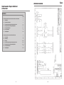
1
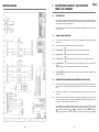
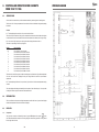
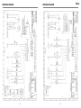
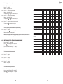
France
Foster Refrigerator France SA
Tel: 33 (01) 34 302222. Fax: 33 (01) 30 376874.
Austria
Foster Refrigerator Austria
Tel: 43 (1) 815 1511. Fax: 43 (1) 813 2936.
Spain/Portugal
Foster Refrigerator (Iberica)
Tel: 34 (43) 463222. Fax: 34 (43) 463246.
Holland
Hobart Foster Holland BV
Tel: 31 (348) 433 331. Fax: 31 (348) 430 117.
Belgium
Hobart Foster Belgium NV
Tel: 32 (16) 606040. Fax: 32 (16) 605988.
Denmark
Hobart Foster Denmark A/S
Tel: 45 (98) 141199. Fax: 45 (98) 141703.
Norway
Hobart Foster Norge A/S
Tel: 47 (67) 533878. Fax: 47 (67) 536742.
Sweden
Hobart Foster Sverige AB
Tel: 46 (0) 8 584 50 920. Fax: 46 (0) 8 584 50 929.
PMI FEG Offices
Asia/Pacific
PMI Food Equipment Group (Hong Kong) Ltd.
Tel: (852) 3419315. Fax: (852) 3413914.
Middle East
PMI Food Equipment Group (Dubai).
Tel: 971 (4) 497393. Fax: 971 (4) 448232.
Japan
PMI Food Equipment Group (Japan) Inc.
Tel: 81 (3) 37443511. Fax: 81 (3) 37444011.
Malaysia
PMI Food Equipment Group (Malaysia) Inc.
Tel: 603 780 6779. Fax: 603 781 4535.
Singapore
PMI Food Equipment Group (Singapore) Inc.
Tel: 65 665 0487. Fax: 65 665 0487.
Foster Refrigerator Group of Companies,
Oldmedow Road, King’s Lynn,
Norfolk PE30 4JU
England
Tel: 01553 691122
Fax: 01553 691447
GS Cab-Count/SM/7/02
Service Manual
Germany
Foster Refrigerator GmbH
Tel: 49 (202) 64870. Fax: 49 (202) 643044.
Gastronorm
Supra Cabinet
& Counter
By Appointment to
Her Majesty Queen Elizabeth II
Suppliers of Commercial Refrigeration
Foster Refrigerator (UK) Ltd King’s Lynn
Service Manual
Foster European Operations
WIRING DIAGRAM
Gastronorm Supra Cabinet
& Counter
CONTENTS
Page
1.
2.
Controller Operation For Cabinets and Counters From 1996 Onwards
3
1.1
Introduction
3
1.2
Symbols And Indicators
3
1.3
Parameter Programming And Operating Instructions
3-4
1.4
Entering Factory Set And Programming Mode
4-5
1.5
Factory Set Parameters
6-7
1.6
Error Annunciation
1.7
Wiring Diagrams
8
9 - 11
Controller Operation For Cabinets From 1994 To 1996
12
2.1
Service Data
12
2.2
Introduction
12
2.3
Displays
12 - 13
2.4
Parameter Programming And Operating Instructions
13 - 14
2.5
Entering Factory Set And Programming Mode
14 - 15
2.6
Factory Set Parameters
2.7
Wiring Diagrams
16
17 - 19
2
19
WIRING DIAGRAM
1.
1.1
GASTRONORM CABINETS AND COUNTERS
FROM 1996 ONWARDS
INTRODUCTION
A microprocessor temperature controller which holds and displays a pre-set counter / cabinet air temperature.
The controller performs many other functions which include automatic defrost initiation, alarm functions
and calculation of stored product temperature.
The display fascia panel and microprocessor control board form a single integral unit, from here on referred
to as the controller.
1.2
SYMBOLS AND INDICATORS
1.2.1
The symbols on the fascia panel consist of a seven segment display together with the following indicators
and symbols.
1.2.2
Illuminated indicators — these appear adjacent to the three digit display.
1.2.3
Condensing Unit -
LED illuminated green when Condensing Unit output is high.
1.2.4
Evaporator Fans -
LED illuminated green when Evaporator Fan output is high.
1.2.5
Condenser Clean -
LED Illuminated green when Condenser Clean time (P2) has elapsed.
1.2.6
Food temperature LED illuminated amber when Calculated Stored Product Temperature is
outside
the pre-set High and Low Foot Temperature Alarm Settings (C2 and C3 respectively).
1.2.7
Door Open - ! LED illuminated red when the Door Alarm Delay (A1) has elapsed. Extinguished when
all doors are re-closed.
1.3
PARAMETER PROGRAMMING AND OPERATING INSTRUCTIONS
1.3.1
The parameters which control the operation are divided into User Parameters (those to which the operator
has access) and the Factory Set parameters (additional parameters not intended to be modified by the
user).
1.3.2
User Parameter Programming — Access to the user parameters can be made by a simple series of key
operations.
1.3.3
While the controller is switched in and operating normally, pressing the SET button will cause the controller
to enter the programming mode, with the display showing SET. Further operation of the SET key causes
the display to scroll through the User Parameters C1 to C4.
While the SET key is depressed, the parameter number is displayed, releasing the SET key causes the
value of the parameter to be displayed. A parameter value may be altered using the
(increment) or
(Decrement key). While the
or
key is depressed, the parameter number is displayed,
releasing the key causes the new value of the parameter (incremented or decremented) to be displayed.
18
3
WIRING DIAGRAM
1.3.4
To exit the User Parameter Programming Mode and return to normal operation of the Controller, the
key must be pressed while holding down the SET key. While both buttons are depressed the display will
show FIN and releasing the buttons will return the Controller to normal operation with the display showing
internal air temperature. Note, while the Controller is in the programming mode, control of the cabinet/
counter refrigeration components is still maintained.
Note, while in the programming mode, if no button is depressed for two minutes, the Controller will revert
to normal operation.
1.3.5
Example:
Press SET
Press SET
Display shows SET
Display shows C1
Display shows value
Display shows C2
Display shows value
Press SET
Pressing
or
(while SET button is depressed)
(when SET button is released)
(while SET button is depressed)
(when SET button is released)
buttons will cause the value of a parameter to incremement.
Press
Display shows C2
Display shows new value
(while the
(when the
Press SET
Display shows C3
Display shows new value
(while the SET button is depressed)
(when the SET button is released)
Press SET
Display shows C4
Display shows ne value
(while the SET button is depressed)
(when the SET button is released)
button is depressed)
button is released)
Pressing the SET button after the last parameter will cause the display to return again to the first
parameter.
Press SET
Display shows C1
Display shows value
(while SET button is depressed)
(when SET button is released)
If desired, the controller can be caused to exit the programming mode having saved any new parameter
values.
Press SET
&
together
Display shows FIN
Display shown Air Temp
(while buttons are depressed)
(when buttons are released)
1.4
ENTERING FACTORY SET AND PROGRAMMING MODE
1.4.1
Display Factory Parameter
Access to the Factory Parameter settings is made by first entering the User Programme C1 to C4. Holding
down the SET key and pressing the
key will cause the controller to display FIN. Releasing the
key and depressing the ‘I/O’ (with the SET key still pressed) will cause the controller to display LLL.
Pressing the SET key will scroll through to parameter L1.
4
17
2.7
FACTORY SET PARAMETERS
SET No.
1
CABINET MODELS
SET No.
GS
GS
GS
GS
GS
501, 601, 1131, 1351, 2101
501, 601, 1131, 1351, 2101
501, 601, 1131
501, 601, 1131
ALL (High Temp Section)
HT
HTR
HU
HUR
HLT
GS
GS
GS
GS
501, 601, 1131
501, 601, 1131
501, 601, 1131
501, 601, 1131
WT
WTR
WU
WUR
3
GS
601, 1131
FT
4
GS
501, 601, 1131, 1351
LT
5
GS
501, 601, 1131, 1351
MT
6
GS
501, 601, 1131, 1351
CT
2
Parameter Set No.
CABINET MODELS
1.4.2
7
GS
GS
GS
GS
2101
501, 601, 1131, 1351, 2101
501, 601, 1131
501, 601, 1131
MT
MTR
MU
MUR
8
GS
GS
GS
GS
2101
501, 601, 1131, 1351, 2101
501, 601, 1131
501, 601, 1131
CT
CTR
CU
CUR
9
GS
GS
501, 601
ALL (Low Temp Section)
LU
HLT
10
GS
GS
501, 601, 1351
1131
LTR
LUR
GS
GS
GS
2101
2101
1131
LT
LTR
LU
11
1
2
3
4
5
6
7
8
9
10
11
Parameter
Temperature Set Point
C1
2
10
-1
-21
-1
0
-2
0
-21
-21
-21
C1
High Food Temp Alarm
C2
8
15
5
-15
5
8
5
8
-15
-15
-15
C2
Low Temp Food Alarm
C3
0
4
-3
-25
-4
-1
-4
-1
-25
-25
-25
C3
Condenser Clean Interval
C4
0
0
0
0
0
0
0
0
0
0
0
C4
Time Since Last Defrost
L1
L1
Door Open Factor
L2
L2
Door Open Factored At Last Alarm Cond.L3
L2
Temperature Differential
P1
3
2
2
3
2
2
2
2
3
3
3
P1
Condenser Clean Interval
P2
15
15
15
15
15
15
15
15
15
15
15
P2
Compressor Rest Time
P3
0
0
0
0
0
0
0
0
0
0
0
P3
Food Probe Offset
P4
0
0
0
0
0
0
0
0
0
0
0
P4
Maximum Set Point
P5
5
15
2
-15
0
2
0
2
-15
-15
-15
P5
Minimum Set Point
P6
1
5
-2
-25
-3
-1
-3
-1
-25
-25
-25
P6
Fans On In Defrost
P7
1
1
1
0
0
0
0
0
0
0
0
P7
Defrost Type
D1
0
0
0
1
1
1
0
0
0
0
0
D1
Defrost Per Day
D2
4
4
4
4
4
4
4
4
4
4
4
D2
Termination Temperature
D3
30
30
30
30
30
30
15
15
20
30
15
D3
Termination Time
D4
15
15
15
10
5
5
10
10
15
15
12
D4
Drain Down Time
D5
1
0
0
1
1
1
1
1
1
1
1
D5
Fan Delay Time
D6
5
5
5
5
3
3
3
3
5
5
5
D6
Fan Delay Temperature
D7
-5
-5
-5
-5
-5
-5
-5
-5
-5
-5
-5
D7
Door Alarm Delay
A1
5
5
5
5
5
5
5
5
5
5
5
A1
Alarm Required
A2
1
1
1
1
1
1
1
1
1
1
1
A2
Probe Failure Response
A3
1
1
1
0
1
1
1
1
0
0
0
A3
Max High Alarm
A4
10
20
8
-10
8
10
8
10
-10
-10
-10
A4
Min Low Alarm
A5
-5
2
-5
-30
-5
-2
-5
-2
-30
-30
-30
A5
Recovery Time
A6
5
5
5
8
5
5
5
5
5
5
5
A6
16
Display / Amend Parameters P1 - P6.
Holding the SET key and pressing the
key will cause the controller to display ‘OPS’.
Pressing the SET key will scroll through parameters P1 to P6.
Parameter values may be altered using
or
key.
1.4.3
Display / Amend Parameters D1 - D8.
Holding the SET key and pressing the
key will cause the controller to display ‘df’.
Pressing the SET key will scroll through parameters D1 to D8.
Parameter values may be altered using
or
key.
1.4.4
Display / Amend Parameters A1 - A6.
key will cause the controller to display ‘AL’.
Holding the SET key and pressing the
Pressing the SET key will scroll through parameters A1 to A8.
or
key.
Parameter values may be altered using
1.4.5
Exit Factory Parameters.
To exit Factory Parameter Programming and return to normal operation of the controller, the SET key must
be held down and the
key must be pressed.
While both buttons are pressed, the display will show FIN and releasing the buttons will return the controller
to normal operation.
Note, while in the programming mode, if no button is pressed for a period of thirty seconds, the controller
will revert to normal operation.
1.4.6
Defrost.
During the Defrost operation the display will show DEF. The evaporator indicator will be off. At the end
of the defrost operation there will be a drain down period when neither the compressor or evaporator will
run, therefore both indicator lights will be off. During this period DEF will be displayed.
Upon completion of the drain down period, the Recovery operation is initiated with the display showing
REC.
The compressor will run and the green compressor on indicator will illuminate.
On completion of the fan delay period (either by temperature or time) the evaporator fan will run with the
green fan indicator LED illuminated.
At the end of the Recovery time the display will revert back to displaying the internal cabinet
temperature.
To initiate a MANUAL DEFROST press and hold the defrost button, press the
show DEF, release both buttons.
The defrost will be the same as an automatic defrost.
5
button, the display will
1.5
FACTORY SET PARAMETERS
SET No.
1
CABINET MODELS
COUNTER MODELS
GS
GS
GS
GS
GS
501, 601, 1131, 1351, 2101
501, 601, 1131, 1351, 2101
501, 601, 1131
501, 601, 1131
ALL (High Temp Section)
HT
HTR
HU
HUR
HLT
GSC
GSC
ALL
ALL
2
GS
GS
GS
GS
501, 601, 1131
501, 601, 1131
501, 601, 1131
501, 601, 1131
WT
WTR
WU
WUR
3
GS
601, 1131
FT
GSC
GSC
ALL
ALL
F
FR
4
GS
501, 601, 1131, 1351
LT
GSC
ALL
L
5
GS
501, 601, 1131, 1351
MT
GSC
ALL
M
6
GS
501, 601, 1131, 1351
CT
GSC
ALL
C
7
GS
GS
GS
GS
2101
501, 601, 1131, 1351, 2101
501, 601, 1131
501, 601, 1131
MT
MTR
MU
MUR
GSC
ALL
MR
GS
GS
GS
GS
2101
501, 601, 1131, 1351, 2101
501, 601, 1131
501, 601, 1131
CT
CTR
CU
CUR
GSC
GS
GS
501, 601
ALL (Low Temp Section)
LU
HLT
GSC
10
GS
GS
501, 601, 1351
ALL (Low Temp Section)
LTR
LUR
11
GS
GS
GS
2101
2101
1131
LT
LTR
LU
2.5.5
Access to the Factory Parameter settings is made by first entering the User Programme C1 to C4.
Holding down the SET key and pressing the
key will cause the controller to display FIN.
key and depressing the ‘I/O’ (with the SET key still pressed) will cause the controller
Releasing the
to display LLL. Pressing the SET key will scroll through the parameters L1, L2 and L3.
H
HR
2.5.6
9
Display / Amend Parameters P1 - P7.
Holding the SET key and pressing the
key will cause the controller to display ‘OPS’.
Pressing the SET key will scroll through the parameters P1 to P7.
or
key.
Parameter values may be altered using the
2.5.7
8
Display Factory Parameter.
Holding the SET key and pressing the
key will cause the controller to display ‘df’.
Pressing the SET key will scroll through the parameters D1 to D7.
or
key.
Parameter values may be altered using the
2.5.8
Display / Amend Parameters A1 - A6.
Holding the SET key and pressing the
key will cause the controller to display ‘AL’.
Pressing the SET key will scroll through the parameters A1 to A6.
Parameter values may be altered using the
or
key.
2.5.9
ALL
Display / Amend Parameters D1 - D7.
Exit Factory Parameters.
To exit Factory Parameter Programming and return to normal operation of the controller, the SET key must
be held down and the
must be pressed.
While both buttons are pressed, the display will show FIN and releasing the buttons will return the controller
to normal operation.
CR
Note, while in the programming mode, if no button is pressed for a period of thirty seconds, the controller
will revert to normal operation.
ALL
LR
2.5.10
Defrost.
During the Defrost operation the display will show DEF. The evaporator indicator will be off. At the end
of the defrost operation there will be a drain down period when neither the compressor or evaporator will
run, therefore both indicator lights will be off. During this period DEF will be displayed.
Upon completion of the drain down period, the Recovery operation is initiated with the display showing
REC.
The compressor will run and the green compressor on indicator will illuminate.
On completion of the fan delay period (either by temperature or time) the evaporator fan will run with the
green fan indicator LED illuminated.
At the end of the Recovery time the display will revert back to displaying the internal cabinet
temperature.
To initiate a MANUAL DEFROST press and hold the defrost button, press the
show DEF, release both buttons.
The defrost will be the same as an automatic defrost.
6
15
button, the display will
To change high/low alarm setting
2.4.7
2.4.8
2.4.9
2.4.10
Press SET — display SET.
Press SET — display C1.
Release — display value of C1.
Parameter Set No.
Press SET — display C2 (high temp alarm).
Release — display value of C2.
To adjust press
or
as instruction 1.3.5 page 4.
Parameter
2.5
2
3
4
5
6
7
8
9
10
11
Temperature Set Point
C1
1
10
-1
-21
-2
0
-2
0
-21
-21
-21
C1
High Food Temp Alarm
C2
8
19
5
-15
5
8
5
8
-15
-15
-15
C2
Press SET — display C3 (low temp alarm).
Release — display value of C3.
To adjust press
or
as instruction 1.3.5 page 4.
Low Temp Food Alarm
C3
0
4
-3
-25
-4
-1
-4
-1
-25
-25
-25
C3
Condenser Clean Interval
C4
0
0
0
0
0
0
0
0
0
0
0
C4
Time Since Last Defrost
L1
Press SET — display C4 (condenser clean, hours reset).
Release — display value — compressor run hours.
To reset to zero
as instruction 1.3.5 page 4.
Temperature Differential
P1
3
2
2
3
2
2
2
2
3
3
3
P1
Time Between Condenser Clean
P2
15
15
15
15
15
15
15
15
15
15
15
P2
Maximum Set Point
P3
5
17
2
-15
0
2
0
2
-15
-15
-15
P3
Minimum Set Point
P4
1
5
-2
-25
-3
-1
-3
-1
-25
-25
-25
P4
Evap Fan Operating During Defrost
P5
1
1
1
0
0
0
0
0
0
0
0
P5
Press SET — display C1.
Hold SET and press
button — display FIN
Release both buttons for normal operation.
Air Temperature Offset
P6
0
0
0
0
0
0
0
0
0
0
0
P6
Number of Defrost Per Day
D1
4
4
4
4
4
4
4
4
4
4
4
D1
Termination Temperature
D2
30
30
30
30
30
30
15
15
20
30
15
D2
NOTE: If no changes are made during a programming operation for 2 minutes, the controller will
reset itself automatically for normal operation.
Termination Time
D3
15
15
15
10
5
5
10
10
15
15
12
D3
Defrost Type
D4
0
0
0
1
1
1
0
0
0
0
0
D4
Drain Down Time
D5
1
0
1
1
1
1
1
1
1
1
1
D5
Fan Delay Time
D6
5
5
5
5
3
3
3
3
5
5
5
D6
Fan Delay Temperature
D7
-5
-5
-5
-5
-5
-5
-5
-5
-5
-5
-5
D7
Recovery Time
D8
5
5
5
8
5
5
5
5
5
5
5
D8
Door Alarm Delay
A1
5
5
5
5
5
5
5
5
5
5
5
A1
Internal Audible Alarm Select
A2
1
1
1
1
1
1
1
1
1
1
1
A2
External Alarm Select
A3
1
1
1
1
1
1
1
1
1
1
1
A3
Probe Failure Response
A4
0
0
0
0
0
0
0
0
1
1
1
A4
Max. High Food Temp Alarm
A5
10
20
8
-10
8
10
8
10
-10
-10
-10
A5
Min. Low Food Temp Alarm
A6
-5
2
-5
-30
-5
-2
-5
-2
-30
-30
-30
A6
To exit programming and allow the cabinet to operate normally.
2.4.11
1
ENTERING FACTORY SET AND PROGRAMMING MODE
Press and hold SET — display SET.
whilst still holding SET — display FIN.
Press
Release
— display FIN.
Press on/off I/O whilst still holding SET — display LLL.
Release all buttons.
To change parameter in information mode.
2.5.1
Press SET — display L1.
Release — display value.
2.5.2
Press SET — display L2
Release — display value.
2.5.3
Press SET — display L3.
Release — display value.
L1
To exit without entering any other value.
2.5.4
Press SET — display L1.
Press
whilst still holding SET — display SET.
Release
whilst still holding SET — display FIN.
Release both buttons.
14
7
1.6
ERROR ANNUNCIATION
1.6.1
Should a temperature probe failure occur the controller will indicate the fault by flashing on the fascia: PF1
or PF2.
2.3.2
The operation of the evaporator is indicated by means of a green LED adjacent to the symbol
whilst
it is illuminated.
When the door is opened the green LED will ‘flash’. When closed it will revert back to a solid display.
PF1. When an air probe fault occurs the Condensing Unit Output may fall low depending on the status
of the parameter Probe Failure Response (A4).
PF2. If an evaporator probe failure occurs, the parameter defrost Termination Temperature (D2) is ignored
and defrosts are caused to terminate only after the period Termination Time (D3) has elapsed.
Please Note:
As of November 1998 the RED defrost probe (PF2) has been removed and replaced with a 5.1kOhm
Resistor.
All new controllers come with the resistor fitted. Should you require resistors you can contact the Product
Support at King’s Lynn and they will be issued free of charge.
For Supra Cabinet and Counter products having hot gas defrost, no changes are required to the parameter
settings.
2.3.3
Ferrite Ring Suppressor on the Supra Controller.
As of October 1998 a ferrite core has been fitted to give immunity to the controller from mains borne electrical
noise (“EFT” = Electrical Fast Transients). The ferrite operates by absorbing energy from the noise, thus
reducing the amount of noise passed on to the controller.
For further information contact the Product Support Department on Telephone Number: 01553 691122.
1.5.3
2.3.4
8
Food Temperature Value.
The temperature of the ‘food’ within the cabinet is monitored via the microprocessor which ‘calculates’
from the air sensing probe the stored food temperature. If this temperature is within the high/low food
temperature conditions set within the factory service parameters, the green LED at the top left hand corner
of the display window will be illuminated. If it is outside the high/low settings the red LED adjacent to the
! symbol will be illuminated.
It should be noted that as the monitoring system simulates actual food there will be a delay in reaching
the ‘safe’ conditions after initial start up of the cabinet. This time could be up to 6-8 hours depending on
storage temperature.
2.4
PARAMETER PROGRAMMING AND OPERATING INSTRUCTIONS
The controller is a multi-function microprocessor having five levels of control operation. The ‘end user’ has
access only to one level limiting accidental changing of operation parameters.
2.4.1
Switching On.
With power connected to the cabinet the display on the controller fascia will be – – –
Switch on by depressing the on/off button. The display will show actual internal temperature plus compressor
and evaporator fan LED’s.
Door Open Alarm
When the door is open the evaporator fans are switched off. The green LED will flash. After a preprogrammed set point an audible alarm will be turned on and the red alarm LED will flash. This alarm will
be cleared when the door is closed.
If the door is left open for more than five minutes the compressor will also be turned off, i.e., nothing will
be on except the lights.
Condenser Clean.
Adjacent to the condenser symbol
is a green LED that illuminates if the compressor run time exceeds
the value entered in the service programme (the value is based on hundreds of hours). If illuminated clean
the condenser and re-set the compressor run hours in the customer programme C4.
For Supra Cabinet and Counter electric defrost models, a heat limit Klixon should be fitted as an additional
safety device. The type of Klixon to be fitted will depend on the particular model, for further information on
type contact the Product Support Department on Telephone Number: 01553 691122.
The effect of removing the probe will mean that the coil probe will always be shown as between -1°C or
+1°C when pressing the
button.
1.5.2
Evaporator Fan.
2.4.2
User Operation.
Cut out temperature.
2.4.3
Press SET — display — SET
2.4.4
Press SET again — display — C1
Release — display — cut out temperature
2.4.5
To adjust — press
buttons: during this process as the
or
buttons is pressed
or
the parameter will be displayed and releasing it will show the value. As the button is continuously pressed
the value will change. When the required value is set cease pressing the
or
buttons.
2.4.6
To exit operation press SET — display C2.
Hold SET press
— display FIN.
Release both buttons. The cabinet will operate to the new value.
13
2.
2.1
CONTROLLER OPERATION FOR CABINETS
FROM 1994 TO 1996
WIRING DIAGRAM
SERVICE DATA
One function of the controller is to provide certain data which may assist engineers in fault diagnosis.
The function is ‘LLL’ in factory set parameters. Access into this function is described in the general operating
instructions.
Function
L1 The data displayed shows the time in hours since the last defrost.
This can be of help if a complaint of ‘icing’ up of the evaporator has been received as this allows the engineer
to check that defrost occurs and whether under certain circumstances the defrost period is long enough.
L2 In the event of high frequency door opening the value is displayed between 0 and 10.
This value is a percentage of the door opening time.
Display
00
1
2
3
4
5
6
7
8
9
10
Door Operation
Door closed for 100% of the time.
Door has been open for 10% of the time.
Door has been open for 20% of the time.
Door has been open for 30% of the time.
Door has been open for 40% of the time.
Door has been open for 50% of the time.
Door has been open for 60% of the time.
Door has been open for 70% of the time.
Door has been open for 80% of the time.
Door has been open for 90% of the time.
Door has been open for 100% of the time.
This data can be useful if an engineer is called to investigate poor performance / high cabinet temperature
as he can see from the factor displayed if heavy door usage could be the cause of the performance
experienced.
L3 The data displayed will be the door open factor (L2) at the time of the last overtemperature warning
occurred.
The values displayed will change automatically as the operation of the cabinet changes. It is not possible
to change the values using the increment and decrement buttons.
2.2
INTRODUCTION
This is a multi-function microprocessor digital temperature controller which not only controls and displays
the cabinet temperature but has other features and displays.
2.3
DISPLAYS
2.3.1
Compressor.
The cycle of the compressor is indicated by means of a green LED adjacent to the symbol
on the
facia. When illuminated the compressor is running during the normal running operation or during defrost
if the hot gas method is used.
12
9
WIRING DIAGRAM
WIRING DIAGRAM
10
11
WIRING DIAGRAM
WIRING DIAGRAM
10
11
2.
2.1
CONTROLLER OPERATION FOR CABINETS
FROM 1994 TO 1996
WIRING DIAGRAM
SERVICE DATA
One function of the controller is to provide certain data which may assist engineers in fault diagnosis.
The function is ‘LLL’ in factory set parameters. Access into this function is described in the general operating
instructions.
Function
L1 The data displayed shows the time in hours since the last defrost.
This can be of help if a complaint of ‘icing’ up of the evaporator has been received as this allows the engineer
to check that defrost occurs and whether under certain circumstances the defrost period is long enough.
L2 In the event of high frequency door opening the value is displayed between 0 and 10.
This value is a percentage of the door opening time.
Display
00
1
2
3
4
5
6
7
8
9
10
Door Operation
Door closed for 100% of the time.
Door has been open for 10% of the time.
Door has been open for 20% of the time.
Door has been open for 30% of the time.
Door has been open for 40% of the time.
Door has been open for 50% of the time.
Door has been open for 60% of the time.
Door has been open for 70% of the time.
Door has been open for 80% of the time.
Door has been open for 90% of the time.
Door has been open for 100% of the time.
This data can be useful if an engineer is called to investigate poor performance / high cabinet temperature
as he can see from the factor displayed if heavy door usage could be the cause of the performance
experienced.
L3 The data displayed will be the door open factor (L2) at the time of the last overtemperature warning
occurred.
The values displayed will change automatically as the operation of the cabinet changes. It is not possible
to change the values using the increment and decrement buttons.
2.2
INTRODUCTION
This is a multi-function microprocessor digital temperature controller which not only controls and displays
the cabinet temperature but has other features and displays.
2.3
DISPLAYS
2.3.1
Compressor.
The cycle of the compressor is indicated by means of a green LED adjacent to the symbol
on the
facia. When illuminated the compressor is running during the normal running operation or during defrost
if the hot gas method is used.
12
9
1.6
ERROR ANNUNCIATION
1.6.1
Should a temperature probe failure occur the controller will indicate the fault by flashing on the fascia: PF1
or PF2.
2.3.2
The operation of the evaporator is indicated by means of a green LED adjacent to the symbol
whilst
it is illuminated.
When the door is opened the green LED will ‘flash’. When closed it will revert back to a solid display.
PF1. When an air probe fault occurs the Condensing Unit Output may fall low depending on the status
of the parameter Probe Failure Response (A4).
PF2. If an evaporator probe failure occurs, the parameter defrost Termination Temperature (D2) is ignored
and defrosts are caused to terminate only after the period Termination Time (D3) has elapsed.
Please Note:
As of November 1998 the RED defrost probe (PF2) has been removed and replaced with a 5.1kOhm
Resistor.
All new controllers come with the resistor fitted. Should you require resistors you can contact the Product
Support at King’s Lynn and they will be issued free of charge.
For Supra Cabinet and Counter products having hot gas defrost, no changes are required to the parameter
settings.
2.3.3
Ferrite Ring Suppressor on the Supra Controller.
As of October 1998 a ferrite core has been fitted to give immunity to the controller from mains borne electrical
noise (“EFT” = Electrical Fast Transients). The ferrite operates by absorbing energy from the noise, thus
reducing the amount of noise passed on to the controller.
For further information contact the Product Support Department on Telephone Number: 01553 691122.
1.5.3
2.3.4
8
Food Temperature Value.
The temperature of the ‘food’ within the cabinet is monitored via the microprocessor which ‘calculates’
from the air sensing probe the stored food temperature. If this temperature is within the high/low food
temperature conditions set within the factory service parameters, the green LED at the top left hand corner
of the display window will be illuminated. If it is outside the high/low settings the red LED adjacent to the
! symbol will be illuminated.
It should be noted that as the monitoring system simulates actual food there will be a delay in reaching
the ‘safe’ conditions after initial start up of the cabinet. This time could be up to 6-8 hours depending on
storage temperature.
2.4
PARAMETER PROGRAMMING AND OPERATING INSTRUCTIONS
The controller is a multi-function microprocessor having five levels of control operation. The ‘end user’ has
access only to one level limiting accidental changing of operation parameters.
2.4.1
Switching On.
With power connected to the cabinet the display on the controller fascia will be – – –
Switch on by depressing the on/off button. The display will show actual internal temperature plus compressor
and evaporator fan LED’s.
Door Open Alarm
When the door is open the evaporator fans are switched off. The green LED will flash. After a preprogrammed set point an audible alarm will be turned on and the red alarm LED will flash. This alarm will
be cleared when the door is closed.
If the door is left open for more than five minutes the compressor will also be turned off, i.e., nothing will
be on except the lights.
Condenser Clean.
Adjacent to the condenser symbol
is a green LED that illuminates if the compressor run time exceeds
the value entered in the service programme (the value is based on hundreds of hours). If illuminated clean
the condenser and re-set the compressor run hours in the customer programme C4.
For Supra Cabinet and Counter electric defrost models, a heat limit Klixon should be fitted as an additional
safety device. The type of Klixon to be fitted will depend on the particular model, for further information on
type contact the Product Support Department on Telephone Number: 01553 691122.
The effect of removing the probe will mean that the coil probe will always be shown as between -1°C or
+1°C when pressing the
button.
1.5.2
Evaporator Fan.
2.4.2
User Operation.
Cut out temperature.
2.4.3
Press SET — display — SET
2.4.4
Press SET again — display — C1
Release — display — cut out temperature
2.4.5
To adjust — press
buttons: during this process as the
or
buttons is pressed
or
the parameter will be displayed and releasing it will show the value. As the button is continuously pressed
the value will change. When the required value is set cease pressing the
or
buttons.
2.4.6
To exit operation press SET — display C2.
Hold SET press
— display FIN.
Release both buttons. The cabinet will operate to the new value.
13
To change high/low alarm setting
2.4.7
2.4.8
2.4.9
2.4.10
Press SET — display SET.
Press SET — display C1.
Release — display value of C1.
Parameter Set No.
Press SET — display C2 (high temp alarm).
Release — display value of C2.
To adjust press
or
as instruction 1.3.5 page 4.
Parameter
2.5
2
3
4
5
6
7
8
9
10
11
Temperature Set Point
C1
1
10
-1
-21
-2
0
-2
0
-21
-21
-21
C1
High Food Temp Alarm
C2
8
19
5
-15
5
8
5
8
-15
-15
-15
C2
Press SET — display C3 (low temp alarm).
Release — display value of C3.
To adjust press
or
as instruction 1.3.5 page 4.
Low Temp Food Alarm
C3
0
4
-3
-25
-4
-1
-4
-1
-25
-25
-25
C3
Condenser Clean Interval
C4
0
0
0
0
0
0
0
0
0
0
0
C4
Time Since Last Defrost
L1
Press SET — display C4 (condenser clean, hours reset).
Release — display value — compressor run hours.
To reset to zero
as instruction 1.3.5 page 4.
Temperature Differential
P1
3
2
2
3
2
2
2
2
3
3
3
P1
Time Between Condenser Clean
P2
15
15
15
15
15
15
15
15
15
15
15
P2
Maximum Set Point
P3
5
17
2
-15
0
2
0
2
-15
-15
-15
P3
Minimum Set Point
P4
1
5
-2
-25
-3
-1
-3
-1
-25
-25
-25
P4
Evap Fan Operating During Defrost
P5
1
1
1
0
0
0
0
0
0
0
0
P5
Press SET — display C1.
Hold SET and press
button — display FIN
Release both buttons for normal operation.
Air Temperature Offset
P6
0
0
0
0
0
0
0
0
0
0
0
P6
Number of Defrost Per Day
D1
4
4
4
4
4
4
4
4
4
4
4
D1
Termination Temperature
D2
30
30
30
30
30
30
15
15
20
30
15
D2
NOTE: If no changes are made during a programming operation for 2 minutes, the controller will
reset itself automatically for normal operation.
Termination Time
D3
15
15
15
10
5
5
10
10
15
15
12
D3
Defrost Type
D4
0
0
0
1
1
1
0
0
0
0
0
D4
Drain Down Time
D5
1
0
1
1
1
1
1
1
1
1
1
D5
Fan Delay Time
D6
5
5
5
5
3
3
3
3
5
5
5
D6
Fan Delay Temperature
D7
-5
-5
-5
-5
-5
-5
-5
-5
-5
-5
-5
D7
Recovery Time
D8
5
5
5
8
5
5
5
5
5
5
5
D8
Door Alarm Delay
A1
5
5
5
5
5
5
5
5
5
5
5
A1
Internal Audible Alarm Select
A2
1
1
1
1
1
1
1
1
1
1
1
A2
External Alarm Select
A3
1
1
1
1
1
1
1
1
1
1
1
A3
Probe Failure Response
A4
0
0
0
0
0
0
0
0
1
1
1
A4
Max. High Food Temp Alarm
A5
10
20
8
-10
8
10
8
10
-10
-10
-10
A5
Min. Low Food Temp Alarm
A6
-5
2
-5
-30
-5
-2
-5
-2
-30
-30
-30
A6
To exit programming and allow the cabinet to operate normally.
2.4.11
1
ENTERING FACTORY SET AND PROGRAMMING MODE
Press and hold SET — display SET.
whilst still holding SET — display FIN.
Press
Release
— display FIN.
Press on/off I/O whilst still holding SET — display LLL.
Release all buttons.
To change parameter in information mode.
2.5.1
Press SET — display L1.
Release — display value.
2.5.2
Press SET — display L2
Release — display value.
2.5.3
Press SET — display L3.
Release — display value.
L1
To exit without entering any other value.
2.5.4
Press SET — display L1.
Press
whilst still holding SET — display SET.
Release
whilst still holding SET — display FIN.
Release both buttons.
14
7
1.5
FACTORY SET PARAMETERS
SET No.
1
CABINET MODELS
COUNTER MODELS
GS
GS
GS
GS
GS
501, 601, 1131, 1351, 2101
501, 601, 1131, 1351, 2101
501, 601, 1131
501, 601, 1131
ALL (High Temp Section)
HT
HTR
HU
HUR
HLT
GSC
GSC
ALL
ALL
2
GS
GS
GS
GS
501, 601, 1131
501, 601, 1131
501, 601, 1131
501, 601, 1131
WT
WTR
WU
WUR
3
GS
601, 1131
FT
GSC
GSC
ALL
ALL
F
FR
4
GS
501, 601, 1131, 1351
LT
GSC
ALL
L
5
GS
501, 601, 1131, 1351
MT
GSC
ALL
M
6
GS
501, 601, 1131, 1351
CT
GSC
ALL
C
7
GS
GS
GS
GS
2101
501, 601, 1131, 1351, 2101
501, 601, 1131
501, 601, 1131
MT
MTR
MU
MUR
GSC
ALL
MR
GS
GS
GS
GS
2101
501, 601, 1131, 1351, 2101
501, 601, 1131
501, 601, 1131
CT
CTR
CU
CUR
GSC
GS
GS
501, 601
ALL (Low Temp Section)
LU
HLT
GSC
10
GS
GS
501, 601, 1351
ALL (Low Temp Section)
LTR
LUR
11
GS
GS
GS
2101
2101
1131
LT
LTR
LU
2.5.5
Access to the Factory Parameter settings is made by first entering the User Programme C1 to C4.
Holding down the SET key and pressing the
key will cause the controller to display FIN.
key and depressing the ‘I/O’ (with the SET key still pressed) will cause the controller
Releasing the
to display LLL. Pressing the SET key will scroll through the parameters L1, L2 and L3.
H
HR
2.5.6
9
Display / Amend Parameters P1 - P7.
Holding the SET key and pressing the
key will cause the controller to display ‘OPS’.
Pressing the SET key will scroll through the parameters P1 to P7.
or
key.
Parameter values may be altered using the
2.5.7
8
Display Factory Parameter.
Holding the SET key and pressing the
key will cause the controller to display ‘df’.
Pressing the SET key will scroll through the parameters D1 to D7.
or
key.
Parameter values may be altered using the
2.5.8
Display / Amend Parameters A1 - A6.
Holding the SET key and pressing the
key will cause the controller to display ‘AL’.
Pressing the SET key will scroll through the parameters A1 to A6.
Parameter values may be altered using the
or
key.
2.5.9
ALL
Display / Amend Parameters D1 - D7.
Exit Factory Parameters.
To exit Factory Parameter Programming and return to normal operation of the controller, the SET key must
be held down and the
must be pressed.
While both buttons are pressed, the display will show FIN and releasing the buttons will return the controller
to normal operation.
CR
Note, while in the programming mode, if no button is pressed for a period of thirty seconds, the controller
will revert to normal operation.
ALL
LR
2.5.10
Defrost.
During the Defrost operation the display will show DEF. The evaporator indicator will be off. At the end
of the defrost operation there will be a drain down period when neither the compressor or evaporator will
run, therefore both indicator lights will be off. During this period DEF will be displayed.
Upon completion of the drain down period, the Recovery operation is initiated with the display showing
REC.
The compressor will run and the green compressor on indicator will illuminate.
On completion of the fan delay period (either by temperature or time) the evaporator fan will run with the
green fan indicator LED illuminated.
At the end of the Recovery time the display will revert back to displaying the internal cabinet
temperature.
To initiate a MANUAL DEFROST press and hold the defrost button, press the
show DEF, release both buttons.
The defrost will be the same as an automatic defrost.
6
15
button, the display will
2.7
FACTORY SET PARAMETERS
SET No.
1
CABINET MODELS
SET No.
GS
GS
GS
GS
GS
501, 601, 1131, 1351, 2101
501, 601, 1131, 1351, 2101
501, 601, 1131
501, 601, 1131
ALL (High Temp Section)
HT
HTR
HU
HUR
HLT
GS
GS
GS
GS
501, 601, 1131
501, 601, 1131
501, 601, 1131
501, 601, 1131
WT
WTR
WU
WUR
3
GS
601, 1131
FT
4
GS
501, 601, 1131, 1351
LT
5
GS
501, 601, 1131, 1351
MT
6
GS
501, 601, 1131, 1351
CT
2
Parameter Set No.
CABINET MODELS
1.4.2
7
GS
GS
GS
GS
2101
501, 601, 1131, 1351, 2101
501, 601, 1131
501, 601, 1131
MT
MTR
MU
MUR
8
GS
GS
GS
GS
2101
501, 601, 1131, 1351, 2101
501, 601, 1131
501, 601, 1131
CT
CTR
CU
CUR
9
GS
GS
501, 601
ALL (Low Temp Section)
LU
HLT
10
GS
GS
501, 601, 1351
1131
LTR
LUR
GS
GS
GS
2101
2101
1131
LT
LTR
LU
11
1
2
3
4
5
6
7
8
9
10
11
Parameter
Temperature Set Point
C1
2
10
-1
-21
-1
0
-2
0
-21
-21
-21
C1
High Food Temp Alarm
C2
8
15
5
-15
5
8
5
8
-15
-15
-15
C2
Low Temp Food Alarm
C3
0
4
-3
-25
-4
-1
-4
-1
-25
-25
-25
C3
Condenser Clean Interval
C4
0
0
0
0
0
0
0
0
0
0
0
C4
Time Since Last Defrost
L1
L1
Door Open Factor
L2
L2
Door Open Factored At Last Alarm Cond.L3
L2
Temperature Differential
P1
3
2
2
3
2
2
2
2
3
3
3
P1
Condenser Clean Interval
P2
15
15
15
15
15
15
15
15
15
15
15
P2
Compressor Rest Time
P3
0
0
0
0
0
0
0
0
0
0
0
P3
Food Probe Offset
P4
0
0
0
0
0
0
0
0
0
0
0
P4
Maximum Set Point
P5
5
15
2
-15
0
2
0
2
-15
-15
-15
P5
Minimum Set Point
P6
1
5
-2
-25
-3
-1
-3
-1
-25
-25
-25
P6
Fans On In Defrost
P7
1
1
1
0
0
0
0
0
0
0
0
P7
Defrost Type
D1
0
0
0
1
1
1
0
0
0
0
0
D1
Defrost Per Day
D2
4
4
4
4
4
4
4
4
4
4
4
D2
Termination Temperature
D3
30
30
30
30
30
30
15
15
20
30
15
D3
Termination Time
D4
15
15
15
10
5
5
10
10
15
15
12
D4
Drain Down Time
D5
1
0
0
1
1
1
1
1
1
1
1
D5
Fan Delay Time
D6
5
5
5
5
3
3
3
3
5
5
5
D6
Fan Delay Temperature
D7
-5
-5
-5
-5
-5
-5
-5
-5
-5
-5
-5
D7
Door Alarm Delay
A1
5
5
5
5
5
5
5
5
5
5
5
A1
Alarm Required
A2
1
1
1
1
1
1
1
1
1
1
1
A2
Probe Failure Response
A3
1
1
1
0
1
1
1
1
0
0
0
A3
Max High Alarm
A4
10
20
8
-10
8
10
8
10
-10
-10
-10
A4
Min Low Alarm
A5
-5
2
-5
-30
-5
-2
-5
-2
-30
-30
-30
A5
Recovery Time
A6
5
5
5
8
5
5
5
5
5
5
5
A6
16
Display / Amend Parameters P1 - P6.
Holding the SET key and pressing the
key will cause the controller to display ‘OPS’.
Pressing the SET key will scroll through parameters P1 to P6.
Parameter values may be altered using
or
key.
1.4.3
Display / Amend Parameters D1 - D8.
Holding the SET key and pressing the
key will cause the controller to display ‘df’.
Pressing the SET key will scroll through parameters D1 to D8.
Parameter values may be altered using
or
key.
1.4.4
Display / Amend Parameters A1 - A6.
key will cause the controller to display ‘AL’.
Holding the SET key and pressing the
Pressing the SET key will scroll through parameters A1 to A8.
or
key.
Parameter values may be altered using
1.4.5
Exit Factory Parameters.
To exit Factory Parameter Programming and return to normal operation of the controller, the SET key must
be held down and the
key must be pressed.
While both buttons are pressed, the display will show FIN and releasing the buttons will return the controller
to normal operation.
Note, while in the programming mode, if no button is pressed for a period of thirty seconds, the controller
will revert to normal operation.
1.4.6
Defrost.
During the Defrost operation the display will show DEF. The evaporator indicator will be off. At the end
of the defrost operation there will be a drain down period when neither the compressor or evaporator will
run, therefore both indicator lights will be off. During this period DEF will be displayed.
Upon completion of the drain down period, the Recovery operation is initiated with the display showing
REC.
The compressor will run and the green compressor on indicator will illuminate.
On completion of the fan delay period (either by temperature or time) the evaporator fan will run with the
green fan indicator LED illuminated.
At the end of the Recovery time the display will revert back to displaying the internal cabinet
temperature.
To initiate a MANUAL DEFROST press and hold the defrost button, press the
show DEF, release both buttons.
The defrost will be the same as an automatic defrost.
5
button, the display will
WIRING DIAGRAM
1.3.4
To exit the User Parameter Programming Mode and return to normal operation of the Controller, the
key must be pressed while holding down the SET key. While both buttons are depressed the display will
show FIN and releasing the buttons will return the Controller to normal operation with the display showing
internal air temperature. Note, while the Controller is in the programming mode, control of the cabinet/
counter refrigeration components is still maintained.
Note, while in the programming mode, if no button is depressed for two minutes, the Controller will revert
to normal operation.
1.3.5
Example:
Press SET
Press SET
Display shows SET
Display shows C1
Display shows value
Display shows C2
Display shows value
Press SET
Pressing
or
(while SET button is depressed)
(when SET button is released)
(while SET button is depressed)
(when SET button is released)
buttons will cause the value of a parameter to incremement.
Press
Display shows C2
Display shows new value
(while the
(when the
Press SET
Display shows C3
Display shows new value
(while the SET button is depressed)
(when the SET button is released)
Press SET
Display shows C4
Display shows ne value
(while the SET button is depressed)
(when the SET button is released)
button is depressed)
button is released)
Pressing the SET button after the last parameter will cause the display to return again to the first
parameter.
Press SET
Display shows C1
Display shows value
(while SET button is depressed)
(when SET button is released)
If desired, the controller can be caused to exit the programming mode having saved any new parameter
values.
Press SET
&
together
Display shows FIN
Display shown Air Temp
(while buttons are depressed)
(when buttons are released)
1.4
ENTERING FACTORY SET AND PROGRAMMING MODE
1.4.1
Display Factory Parameter
Access to the Factory Parameter settings is made by first entering the User Programme C1 to C4. Holding
down the SET key and pressing the
key will cause the controller to display FIN. Releasing the
key and depressing the ‘I/O’ (with the SET key still pressed) will cause the controller to display LLL.
Pressing the SET key will scroll through to parameter L1.
4
17
WIRING DIAGRAM
1.
1.1
GASTRONORM CABINETS AND COUNTERS
FROM 1996 ONWARDS
INTRODUCTION
A microprocessor temperature controller which holds and displays a pre-set counter / cabinet air temperature.
The controller performs many other functions which include automatic defrost initiation, alarm functions
and calculation of stored product temperature.
The display fascia panel and microprocessor control board form a single integral unit, from here on referred
to as the controller.
1.2
SYMBOLS AND INDICATORS
1.2.1
The symbols on the fascia panel consist of a seven segment display together with the following indicators
and symbols.
1.2.2
Illuminated indicators — these appear adjacent to the three digit display.
1.2.3
Condensing Unit -
LED illuminated green when Condensing Unit output is high.
1.2.4
Evaporator Fans -
LED illuminated green when Evaporator Fan output is high.
1.2.5
Condenser Clean -
LED Illuminated green when Condenser Clean time (P2) has elapsed.
1.2.6
Food temperature LED illuminated amber when Calculated Stored Product Temperature is
outside
the pre-set High and Low Foot Temperature Alarm Settings (C2 and C3 respectively).
1.2.7
Door Open - ! LED illuminated red when the Door Alarm Delay (A1) has elapsed. Extinguished when
all doors are re-closed.
1.3
PARAMETER PROGRAMMING AND OPERATING INSTRUCTIONS
1.3.1
The parameters which control the operation are divided into User Parameters (those to which the operator
has access) and the Factory Set parameters (additional parameters not intended to be modified by the
user).
1.3.2
User Parameter Programming — Access to the user parameters can be made by a simple series of key
operations.
1.3.3
While the controller is switched in and operating normally, pressing the SET button will cause the controller
to enter the programming mode, with the display showing SET. Further operation of the SET key causes
the display to scroll through the User Parameters C1 to C4.
While the SET key is depressed, the parameter number is displayed, releasing the SET key causes the
value of the parameter to be displayed. A parameter value may be altered using the
(increment) or
(Decrement key). While the
or
key is depressed, the parameter number is displayed,
releasing the key causes the new value of the parameter (incremented or decremented) to be displayed.
18
3
WIRING DIAGRAM
Gastronorm Supra Cabinet
& Counter
CONTENTS
Page
1.
2.
Controller Operation For Cabinets and Counters From 1996 Onwards
3
1.1
Introduction
3
1.2
Symbols And Indicators
3
1.3
Parameter Programming And Operating Instructions
3-4
1.4
Entering Factory Set And Programming Mode
4-5
1.5
Factory Set Parameters
6-7
1.6
Error Annunciation
1.7
Wiring Diagrams
8
9 - 11
Controller Operation For Cabinets From 1994 To 1996
12
2.1
Service Data
12
2.2
Introduction
12
2.3
Displays
12 - 13
2.4
Parameter Programming And Operating Instructions
13 - 14
2.5
Entering Factory Set And Programming Mode
14 - 15
2.6
Factory Set Parameters
2.7
Wiring Diagrams
16
17 - 19
2
19