1
6HUYLFH0DQXDO
02'(/A16CM4H4R18
A16CM4H4R24
A16CM4H4R30
5HIULJHUDQW5$
7DEOHRI&RQWHQWV
7DEOHRI&RQWHQWV
6XPPDU\DQG)HDWXUHV
6DIHW\3UHFDXWLRQV
6SHFLÀFDWLRQV
&RQVWUXFWLRQ9LHZV
5HIULJHUDQW6\VWHP'LDJUDP
6FKHPDWLF'LDJUDP
(OHFWULFDO'DWD
(OHFWULFDO:LULQJ
3ULQWHG&LUFXLW%RDUG )XQFWLRQDQG&RQWURO
,QVWDOODWLRQ0DQXDO
,QVWDOODWLRQ'LPHQVLRQ'LDJUDP
,QVWDOOLQJ7KH2XWGRRU8QLW
(OHFWULFDO&RQQHFWLRQV
&KHFN$IWHU,QVWDOODWLRQ
([SORGHG9LHZVDQG3DUWV/LVW
7URXEOHVKRRWLQJ
0DOIXQFWLRQ,QGLFDWRU
0DOIXQFWLRQ&KHFNLQJDQG(OLPLQDWLRQ
5HPRYDO3URFHGXUH
5HPRYDO3URFHGXUH.
5HPRYDO3URFHGXUH..
6XPPDU\DQG)HDWXUHV
6XPPDU\DQG)HDWXUHV
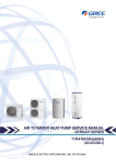
2XWGRRU8QLW
A16CM4H4R18
A16CM4H4R24
A16CM4H4R30
6DIHW\3UHFDXWLRQV
6DIHW\3UHFDXWLRQV
Installing, starting up, and servicing air conditioner can be
hazardous due to system pressure, electrical components,
and equipment location, etc.
Only trained, qualified installers and service personnel are
allowed to install, start-up, and service this equipment.
Untrained personnel can perform basic maintenance functions such as cleaning coils. All other operations should
be performed by trained service personnel.
Make sure the outdoor unit is installed on a stable, level
surface with no accumulation of snow, leaves, or trash
beside.
When handling the equipment, observe precautions in the
manual and on tags, stickers, and labels attached to the
equipment. Follow all safety codes. Wear safety glasses
andwork gloves. Keep quenching cloth and fire extinguisher
nearby when brazing.
Follow all the installation instructions to minimize the risk
of damage from earthquakes, typhoons or strong winds.
Read the instructions thoroughly and follow all warnings or
cautions in literature and attached to the unit. Consult local
building codes and current editions of national as well as
local electrical codes.
Recognize the following safety information:
Warning
Incorrect handling could result in
personal injury or death.
Caution
Incorrect handling may result in
minor injury,or damage to product
or property.
Warning
All electric work must be performed by a licensed technician
according to local regulations and the instructions given in
this manual.
Before installing, modifying, or servicing system, main
electrical disconnect switch must be in the OFF position.
There may be more than 1 disconnect switch. Lock out
and tag switch with a suitable warning label.
Never supply power to the unit unless all wiring and tubing are completed, reconnected and checked.
This system adopts highly dangerous electrical voltage.
Incorrect connection or inadequate grounding can cause
personal injury or death. Stick to the wiring diagram and
all the instructions when wiring.
Have the unit adequately grounded in accordance with
local electrical codes.
Have all wiring connected tightly. Loose connection may
lead to overheating and a possible fire hazard.
All installation or repair work shall be performed by your dealer or a specialized subcontractor as there is the risk of fire,
electric shock, explosion or injury.
Make sure the ceiling/wall is strong enough to bear the
weight of the unit.
Make sure the noise of the outdoor unit does not disturb
neighbors.
Avoid contact between refrigerant and fire as it generates
poisonous gas.
Apply specified refrigerant only. Never have it mixed with
any other refrigerant. Never have air remain in the
refrigerant line as it may lead to rupture and other hazards.
Make sure no refrigerant gas is leaking out when installation is completed.
Should there be refrigerant leakage, the density of refrigerant in the air shall in no way exceed its limited value,
or it may lead to explosion.
Keep your fingers and clothing away from any moving
parts.
Clear the site after installation. Make sure no foreign objects are left in the unit.
Always ensure effective grounding for the unit.
Caution
Never install the unit in a place where a combustible gas
might leak, or it may lead to fire or explosion.
Make a proper provision against noise when the unit is
installed at a telecommunication center or hospital.
Provide an electric leak breaker when it is installed in a
watery place.
Never wash the unit with water.
Handle unit transportation with care. The unit should not
be carried by only one person if it is more than 20kg.
Never touch the heat exchanger fins with bare hands.
Never touch the compressor or refrigerant piping without
wearing glove.
Do not have the unit operate without air filter.
Should any emergency occur, stop the unit and disconnect the power immediately.
Properly insulate any tubing running inside the room to
prevent the water from damaging the wall.
6SHFL¿FDWLRQV
6SHFLÀFDWLRQV
3DUDPHWHU
8QLW
9DOXH
0RGHO
A16CM4H4R18
3URGXFW&RGH
&%:
5DWHG9ROWDJH
3RZHU
6XSSO\
5DWHG)UHTXHQF\
9̚
+]
3KDVHV
3RZHU6XSSO\0RGH
2XWGRRU
&RROLQJ&DSDFLW\0LQ ̚ 0D[
%WXK
a
+HDWLQJ&DSDFLW\0LQ ̚ 0D[
%WXK
a
&RROLQJ3RZHU,QSXW0LQ ̚ 0D[
:
a
+HDWLQJ3RZHU,QSXW0LQ ̚ 0D[
:
a
6((5
%WXZK
+63)
%WXZK
6SHFL¿FDWLRQV
0,768%,6+,(/(&75,&*8$1*=+28&2035(6625
&2/7'
&RPSUHVVRU0DQXIDFWXUHU7UDGHPDUN
&RPSUHVVRU0RGHO
61%)*<0&
&RPSUHVVRU2LO
39()96
&RPSUHVVRU7\SH
5RWDU\
/5$
$
&RPSUHVVRU5/$
$
&RPSUHVVRU3RZHU,QSXW
:
2YHUORDG3URWHFWRU
7KURWWOLQJ0HWKRG
(OHFWURQH[SDQVLRQYDOYH
2SHUDWLRQWHPS
&
a
$PELHQWWHPSFRROLQJ
&
a
$PELHQWWHPSKHDWLQJ
&
&RQGHQVHU)RUP
a
$OXPLQXP)LQFRSSHU7XEH
3LSH'LDPHWHU
PP
ĭ
5RZV¿Q*DS
PP
&RLO/HQJWK/;';:
PP
;;
)DQ0RWRU6SHHG
USP
:
$
2XWSXWRI)DQ0RWRU
2XWGRRU )DQ0RWRU5/$
8QLW
)DQ0RWRU&DSDFLWRU
$LU)ORZ9ROXPHRI2XWGRRU8QLW
ȝ)
PK
)DQ7\SH
)DQ'LDPHWHU
$[LDOÀRZ
PP
'HIURVWLQJ0HWKRG
7
,VRODWLRQ
,
0RLVWXUH3URWHFWLRQ
3HUPLVVLEOH([FHVVLYH2SHUDWLQJ3UHVVXUHIRU
WKH'LVFKDUJH6LGH
3HUPLVVLEOH([FHVVLYH2SHUDWLQJ3UHVVXUHIRU
WKH6XFWLRQ6LGH
ĭ
$XWRPDWLF'HIURVWLQJ
&OLPDWH7\SH
,3
03D
03D
6RXQG3UHVVXUH/HYHO+0/
G%$
6RXQG3RZHU/HYHO+0/
G%$
'LPHQVLRQ:;+;'
PP
;;
'LPHQVLRQRI&DUWRQ%R[/:+
PP
;;
'LPHQVLRQRI3DFNDJH/:+
PP
;;
1HW:HLJKW
NJ
*URVV:HLJKW
NJ
5HIULJHUDQW
5$
5HIULJHUDQW&KDUJH
NJ
/HQJWK
P
JP
*DV$GGLWLRQDO&KDUJH
&RQQHFWLRQ2XWHU'LDPHWHU/LTXLG3LSH
3LSH
2XWHU'LDPHWHU*DV3LSH
17/
PP
ĭ
PP
ĭ
0D['LVWDQFH+HLJKW
P
0D['LVWDQFH/HQJWK
P
6SHFL¿FDWLRQV
3DUDPHWHU
8QLW
9DOXH
0RGHO
A16CM4H4R24
A16CM4H4R30
3URGXFW&RGH
&%:
&%:
9̚
+]
5DWHG9ROWDJH
3RZHU
6XSSO\
5DWHG)UHTXHQF\
3KDVHV
3RZHU6XSSO\0RGH
2XWGRRU
2XWGRRU
&RROLQJ&DSDFLW\0LQ ̚ 0D[
%WXK
a
a
+HDWLQJ&DSDFLW\0LQ ̚ 0D[
%WXK
a
a
&RROLQJ3RZHU,QSXW0LQ ̚ 0D[
:
a
a
+HDWLQJ3RZHU,QSXW0LQ ̚ 0D[
:
a
a
&RROLQJ3RZHU&XUUHQW
$
+HDWLQJ3RZHU&XUUHQW
$
5DWHG,QSXW
:
5DWHG&XUUHQW
$
6((5
%WXZK
+63)
%WXZK
6SHFL¿FDWLRQV
&RPSUHVVRU0DQXIDFWXUHU7UDGHPDUN
&RPSUHVVRU0RGHO
&RPSUHVVRU2LO
&RPSUHVVRU7\SH
0,768%,6+,(/(&75,&
*8$1*=+28&2035(6625
&2/7'
0,768%,6+,(/(&75,&
*8$1*=+28
&2035(6625&2/7'
71%)/+0&
71%)/+0&
39()96
39()96
5RWDU\
5RWDU\
$
&RPSUHVVRU5/$
$
&RPSUHVVRU3RZHU,QSXW
:
/5$
2YHUORDG3URWHFWRU
7KURWWOLQJ0HWKRG
&6&
&6&
(OHFWURQH[SDQVLRQYDOYH
(OHFWURQH[SDQVLRQYDOYH
̚ ̚ 2SHUDWLRQWHPS
&
$PELHQWWHPSFRROLQJ
&
̚ ̚ $PELHQWWHPSKHDWLQJ
&
̚ ̚ $OXPLQXP)LQFRSSHU7XEH
$OXPLQXP)LQFRSSHU7XEH
ĭ
&RQGHQVHU)RUP
3LSH'LDPHWHU
PP
ĭ
5RZV¿Q*DS
PP
&RLO/HQJWK/;';:
PP
;;
;;
USP
)DQ0RWRU6SHHG
2XWGRRU 2XWSXWRI)DQ0RWRU
8QLW
)DQ0RWRU5/$
)DQ0RWRU&DSDFLWRU
$LU)ORZ9ROXPHRI2XWGRRU8QLW
:
$
ȝ)
$[LDOÀRZ
$[LDOÀRZ
P K
)DQ7\SH
)DQ'LDPHWHU
PP
'HIURVWLQJ0HWKRG
&OLPDWH7\SH
,VRODWLRQ
ĭ
ĭ
$XWRPDWLF'HIURVWLQJ
$XWRPDWLF'HIURVWLQJ
7
7
,
,
,3
,3
0RLVWXUH3URWHFWLRQ
3HUPLVVLEOH([FHVVLYH2SHUDWLQJ3UHVVXUH
IRUWKH'LVFKDUJH6LGH
3HUPLVVLEOH([FHVVLYH2SHUDWLQJ3UHVVXUH
IRUWKH6XFWLRQ6LGH
03D
'LPHQVLRQ:;+;'
PP
;;
;;
'LPHQVLRQRI&DUWRQ%R[/:+
PP
;;
;;
'LPHQVLRQRI3DFNDJH/:+
PP
;;
;;
1HW:HLJKW
NJ
*URVV:HLJKW
NJ
03D
5HIULJHUDQW
5$
5$
5HIULJHUDQW&KDUJH
NJ
/HQJWK
P
*DV$GGLWLRQDO&KDUJH
JP
2XWHU'LDPHWHU/LTXLG3LSH
PP
ĭ
ĭ
2XWHU'LDPHWHU*DV3LSH
PP
ĭ
ĭ
P
P
&RQQHFWLRQ0D['LVWDQFH+HLJKW
3LSH
0D['LVWDQFH/HQJWK
7KHDERYHGDWDLVVXEMHFWWRFKDQJHZLWKRXWQRWLFH3OHDVHUHIHUWRWKHQDPHSODWHRIWKHXQLW
&RQVWUFWLRQ9LHZV
&RQVWUXFWLRQ9LHZV
A16CM4H4R18
316
899
378
596
815
343
550
8QLWPP
A16CM4H4R24A16CM4H4R30
892
700
341
396
946
368
560
8QLWPP
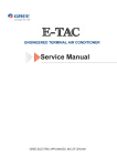
5HIULJHUDQW6\VWHP'LDJUDP
5HIULJHUDQW6\VWHP'LDJUDP
outdoor
indoor
filter
A heat exchanger
A3
A1
filter
B heat exchanger
fan
A2
outdoor heat exchanger
4-way valve
B3
B1
SP
filter
B2
high pressure switch
Note: Not available for 14K/18K
model
discharge silencer
C heat exchanger
C3
C1
filter
D3
C2
D1
filter
D2
gas -liquid separator
Note: Not available for 14K/18K model
A1:A-unit electronic expansion valve B1:B-unit electronic expansion valve
C1:C-unit electronic expansion valve D1:D-unit electronic expansion valve
A2:A-unit gas pipe temperature sensor B2:B-unit gas pipe temperature sensor
C2:C-unit gas pipe temperature sensor D2:D-unit gas pipe temperature sensor
A3:A-unit liquid pipe temperature sensor B3:B-unit liquid pipe temperature sensor
C3:C-unit liquid pipe temperature sensor D3:D-unit liquid pipe temperature sensor
inverter compressor
D heat exchanger
discharge temperature
sensor
6FKHPDWLF'LDJUDP
6FKHPDWLF'LDJUDP
(OHFWULFDO'DWD
0HDQLQJRIPDUNV
6\PERO
&RORUV\PERO
:+
:+,7(
<(
5'
<(*1
97
6\PERO
&RORUV\PERO
6\PERO
*1
*5((1
6$7
<(//2:
%1
%52:1
&203
5('
%8
%/8(
<(//2:*5((1
9,2/(7
%.
%/$&.
2*
25$1*(
3DUWVQDPH
29(5/2$'
&2035(6625
3527(&7,9(($57+
(OHFWULFDO:LULQJ
A16CM4H4R18
6BN
7BU
G
L2
INDOOR UNIT A
5YEGN(GN)
L2
INDOOR UNIT B
4BU
N(1)
2BN
XTB
EKV
EKV
5
5
WH
G
COMP
HEATER
RT2
OUTROOM
TEM.SENSOR
OUTTUBE
TEM.SENSOR
BK
5
EH
16RD
3
HEAT-C
15RD 1
FA
L
L7
WH
FB
OFAN1
LX1-1
U
AP1: Main Board
OG
V
LX1-2
W
TUBE-B
BU
L4
YE
L4
BN
YE BU
YEGN(GN)
WARNING
Please don't touch any terminal when the voltage
FAN MOTOR
WH
BK
0
RD
0
RT4 RT5
Gas Valve Liquid Valve
TEM.SENSOR TEM.SENSOR
BK
BK
0
RD
SAT
R
9BU
S
COMP.
10YE
L4
RD
X1
M
of terminal P(DC+) and N(DC-) at AP1 is higher
than 30V to prevent the risk of electrical shock!
L7
TUBE-A
C1
WH BK RD
14WH
13WH
OVC-COMP
L3
5
4YV
4V
COM-INNER
FB
FA
2
3
L6
BK
GY
XTA
YEGN(GN)
T-SENSOR
EXHAUST
TEM.SENSOR
G
2
3
G
RT1
RT3
N(1)
YEGN(GN)
N1
AC-L
N2
8YEGN(GN)
1BN
3BU
BU
BN
BU
AC-L1
N1
N1
AP2 AC-L2
N2
E(PE)
0
L1 L5
L1
L2
0
XT1
L1
L2
0
POWER
11RD
C(T)
12YEGN(GN)
G
0
RT6 RT7
Gas Valve Liquid Valve
TEM.SENSOR TEM.SENSOR
G
6FKHPDWLF'LDJUDP
A16CM4H4R24
LOAD
LINE
INDOOR UNIT A
5BU
AC-L2
N2
E(PE)
1BN
BU
BN L2
BU
N1
N1
AC-L
N2
T-SENSOR
2
YEGN(GN)
G
TERMINAL
BLOCK
INDOOR UNIT B
3
7BU
ELECTRONIC
EXPANSION VALVE
TERMINAL
BLOCK
INDOOR UNIT C
FB
FA
3BN
N(1)
P
19BU
COM-INNER
WH
XTB
G
2
EKV
EKV
EKV
5
5
5
BK
WH
FA
C1
YE BU
FC
M
YEGN(GN)
G
FAN MOTOR
W
24RD
RD 0
RT8 RT9
QC
YC
Liquid Valve
Gas Valve
Tem.Sensor
Tem.Sensor
BK
0
COMP
W
COMP.
16YEGN(GN)
G
HEAT-C
RD
RD 0
RT6 RT7
QB
YB
Gas Valve Liquid Valve
Tem.Sensor Tem.Sensor
BK
Overload
Protector
V
X1
TUBE-C
BK
0
YE
RD
V
SAT
U
L5 13BU
14YE
15RD
BU
U
LX2-1
TUBE-B
RD 0
RT4 RT5
QA
YA
Gas Valve Liquid Valve
TEM.Sensor Tem.Sensor
BK
17WH
LX2-2
LX1-1
LX1-2
AP1: Main Board
WH
BN
BU
OG
WH
TUBE-A
CAP.
RD
OVC-COMP
5
FB
OFAN
WH BK
L
RD
5
5
HPS
High Pressure Switch
18WH
FC
3
XTC
G
YEGN(GN)
20YE
HPP
GY
2
YEGN(GN)
L4
BK
2BN
N(1)
4-WAY
VALVE
4YV
4V
6BU
EXHAUST
TEM.SENSOR
OUTROOM
TEM.SENSOR
OUTTUBE
TEM.SENSOR
WH
12YEGN(GN)
G
3
RT2
RT3
N(1)
XTA
RT1
0
10BU
L3
TERMINAL
BLOCK
BK
AC-L1
AP2:
N1
Filter Board
0
9YEGN(GN)
POWER
L1 11BN
21BN L
L'
22BU NFILTER N'
G
L1
L2
0
XT1
L1
L2
23RD
0
Compressor
Band Heater
WARNING
Please don't touch any terminal when the voltage
of terminal P(DC+) and N(DC-) at AP1 is higher
than 30V to prevent the risk of electrical shock!
A16CM4H4R30
G
N
LOAD
L1
L
LINE
21BN
22BU
11BN
10BU
L'
N'
AC-L1
N1
FILTER
9YEGN(GN)
AP2
INDOOR UNIT A
5BU
L2
BU
BN L3
BU
N1
AC-L2
N2
E(PE)
N1
AC-L
N2
RT1
T-SENSOR
EXHAUST
TEM.SENSOR
OUTROOM
TEM.SENSOR
OUTTUBE
TEM.SENSOR
0
XT1
L1
L2
0
POWER
L1
L2
RT2
N(1)
INDOOR UNIT B
YEGN(GN)
G
1BN
6BU
2
3
XTB
INDOOR UNIT C
7BU
3BN
N(1)
2
3
XTC
YEGN(GN)
INDOOR UNIT D
N(1)
8BU
4BN
20YE
EKV
EKV
EKV
5
5
5
BK
FA
WH BK
C1
BN
RD
FB
TUBE-A
OFAN
M
TEM.SENSOR
L
BU
5
FC
FD LX1-1
TUBE-B
TEM.SENSOR TEM.SENSOR
U
LX2-1
RD
BK
0
RT8
YE
RD
BK 0
0
RT10
RT9
Please don't touch any terminal when the voltage
of terminal P(DC+) and N(DC-) at AP1 is higher
than 30V to prevent the risk of electrical shock!
HEAT-C W RD
15RD
RD
0
24RD
RT11
Liquid Valve
Gas Valve
TEM.SENSOR TEM.SENSOR
BN:BROWN
WH:WHITE
BU:BLUE
YE:YELLOW
SAT
U
COMP.
V
X1
Gas Valve
Liquid Valve
TEM.SENSOR TEM.SENSOR
13BU
14YE
V
G
WARNING
L5
BU
YE
LX1-2
AP1: Main Board
TUBE-C
TUBE-D
HP
18WH
17WH
OVC-COMP
LX2-2
WH OG
5
BK
YE BU WH
RD
RD BK 0
0
BK 0
0
RT6 RT7
YEGN(GN) Gas Valve RT4 LiquidRT5
Liquid Valve
Valve
Gas Valve
TEM.SENSOR
FAN MOTOR
YE
RD
5
P
19BU
FC FD
5
5
4YV
4V
HPP
EKV
WH
G
L4
COM-INNER
FA FB
2
3
XTD
RT3
G
BK
GY
WH
RD
2BN
N(1)
YEGN(GN)
G
YEGN(GN)
G
12YEGN(GN)
0
2
3
XTA
W 16YEGN(GN)
G
23RD
COMP
HEATER
BK:BLACK
RD:RED
GY:GRAY
YEGN:YELLOW GREEN
7KHVHFLUFXLWGLDJUDPVDUHVXEMHFWWRFKDQJHZLWKRXWQRWLFHSOHDVHUHIHUWRWKHRQHVXSSOLHGZLWKWKHXQLW
6FKHPDWLF'LDJUDP
3ULQWHG&LUFXLW%RDUG
A16CM4H4R18
Ɣ7239,(:
1
2
3
4
5
6
7
8
9
1
2
3
10
4
11
5
6
12
7
Outdoor fan
8
4-way valve
9
13
10
14
11
12
13
17
Ɣ%277209,(:
16
Compressor interface
Unit A liquid valve
and gas valve
Unit B liquid valve
and gas valve
Compressor overload
protector
Temperature sensor
Compressor electric
heater
15
14
15
Chassis electric
heater (reserved)
Unit A electronic
expansion valve
Unit B electronic
expansion valve
Communication
interface with indoor
unit
Communication
neutral wire
Live wire of power
supply
Neutral ire of power
supply
16
Reactor interface1
17
Reactor interface2
6FKHPDWLF'LDJUDP
A16CM4H4R24A16CM4H4R30
Ɣ7239,(:
1
2
3
4
5
6 7
8
9
10
11
12
13
1
Compressor interface
2
Temperature sensor
interface of unit A liquid
valve and gas valve
3
Temperature sensor
interface of unit B liquid
valve and gas valve
4
Temperature sensor
interface of unit C liquid
valve and gas valve
14
15
16
5
17
6
18
7
8
9
22
Ɣ%277209,(:
21
20
19
Temperature sensor
interface of unit D liquid
valve and gas valve
Temperature sensor
interface
Interface of compressor
overload protector
Interface of chassis
electric heater
Interface of compressor
electric heater belt
10
Outdoor fan interface
11
4-way valve interface
12
High voltage protection
interface
Interface of electronic
expansion valve A
Interface of electronic
expansion valve B
Interface of electronic
expansion valve C
Interface of electronic
expansion valve D
Communication wire
interface
Communication neutral
wire interface
13
14
15
16
17
18
19 Input neutral wire interface
20
Input live wire interface
21
PFC input live wire
interface
22
PFC input neutral wire
interface
)XQFWLRQDQG&RQWURO
)XQFWLRQDQG&RQWURO
1 Basic functions of the system
1.1 Cooling Mode
1.1.1 Cooling conditions and process:
If the compressor is in stop status and start the unit for cooling operation, when one of the indoor units reaches the cooling
operation condition, the unit start cooling operation; in this case, the electronic expansion valve, the outdoor fan and the
compressor start operation.
1.1.2 Stop in cooling operation
1.1.2.1 Compressor stops
The compressor stops immediately, the outdoor fan stops after 1min.
1.1.2.2 Some of the indoor units reach the stop condition (the compressor does not stop)
The compressor operates immediately according to the required frequency. For the indoor unit with no requirement, the
corresponding electronic expansion valve is closed to OP.
1.1.3 Cooling mode transfers to heating mode
When the unit transfers to heating mode, the 4-way valve is energized after the compressor stops for 2min. The other disposals
are the same as stopping in cooling mode.
1.1.4 4-way valve: in this mode, the 4-way valve is closed.
1.1.5 Outdoor fan control in cooling mode
The outdoor fan starts before 5s of the starting of compressor. The outdoor fan will run in high speed for 3min after starting and
then it will run in set speed. The fan shall run at every speed for at least 80s. (When the quantity of running indoor unit is
changed, the unit will enter the control described in 1.3.5.1 and 1.3.5.2);
When the compressor stops, the outdoor fan runs at present speed and stops after 1min.
1.2 Dry Mode
1.2.1 The dry conditions and process are the same as those in cooling mode;
1.2.2 The status of 4-way valve: closed;
1.2.3 The temperature setting range: 16 ~ 30ć;
1.2.4 Protection function: the same as those in cooling mode;
1.2.5 In dry mode, the maximum value A of the capacity requirement percentage of single unit is 90% of that in cooling mode.
The open condition of the electronic expansion valve, outdoor fan and compressor is the same as those in cooling mode.
1.3 Heating Mode
1.3.1 Cooling conditions and process:
When one of the indoor units reaches the heating operation condition, the unit starts heating operation.
1.3.2 Stop in heating operation:
1.3.2.1 When all the indoor units reach the stop condition, the compressor stops and the outdoor fan stops after 1min;
1.3.2.2 Some of the indoor units reach the stop condition
The compressor reduces the frequency immediately and operates according to the required frequency;
1.3.2.3 Heating mode transfers to cooling mode(dry mode), fan mode
a. The compressor stops; b. the power of 4-way valve is cut off after 2min; c. the outdoor fan stops after 1min; d. the status of
4-way valve: energized;
)XQFWLRQDQG&RQWURO
1.3.3 Outdoor fan control in heating mode
The outdoor fan starts before 5s of the starting of compressor and then it will run in high speed for 40s;
The fan shall run at every speed for at least 80s;
When the compressor stops, the outdoor fan stops after 1min.
1.3.4 Defrosting function
When the defrosting condition is met, the compressor stops; the electronic expansion valve of all indoor units open in big angle;
the outdoor fan stops after 40s of the stop of compressor, meanwhile, the 4-way valve reverses the direction; after the 4-way
valve reverses the direction, the compressor starts; then begin to calculate the time of defrosting, the frequency of the
compressor rises to reach the defrosting frequency.
1.3.5 Oil-returned control in heating mode
1.3.5.1 Oil-returned condition
The whole unit is operating in low frequency for a long time
1.3.5.2 Oil-returned process in heating mode
The indoor unit displays “H1”
1.3.5.3 Oil-returned finished condition in heating mode
The duration reaches 5min
1.4 Fan Mode
The compressor, the outdoor fan and the 4-way valve are closed; temperature setting range is 16̚30ć.
2. Protection Function
2.1 Mode Conflict Protection of indoor unit
When the setting mode is different of different indoor unit, the unit runs in below status:
a. The mode of the first operating indoor unit is the basic mode, then compare the mode of the other indoor units to see if there
is a conflict. Cooling mode (dry mode) is in conflict with heating mode.
b. Fan mode is in conflict with heating mode and the heating mode is the basic mode. No matter which indoor unit operates first,
the unit will run in heating mode.
2.2 Overload protection function
When the tube temperature is a little low, the compressor raises the operation frequency; when the tube temperature is a little
high, the compressor frequency is restricted or lows down the operation frequency; when the tube temperature is too high, the
compressor protection stops running.
If the discharge temperature protection continuously appears for 6 times, the compressor can’t resume running. The
compressor can resume running after cutting off the power and then putting through the power. (if the running time of the
compressor is longer than 7min, the protection times record will be cleared)
2.3 Discharge Protection Function
When the discharge temperature is a little low, the compressor raises the operation frequency; when the discharge temperature
is a little high, the compressor frequency is restricted or lows down the operation frequency; when the discharge temperature is
too high, the compressor protection stops running.
If the discharge temperature protection continuously appears for 6 times, the compressor can’t resume running. The
compressor can resume running after cutting off the power and then putting through the power. (if the running time of the
compressor is longer than 7min, the protection times record will be cleared)
)XQFWLRQDQG&RQWURO
2.4 Communication malfunction
Detection of the quantity of installed indoor units:
After 3min of energizing, if the outdoor unit does not receive the communication data of certain indoor unit, the outdoor unit will
judge that indoor unit is not installed and will treat it as it is not installed. If the outdoor unit receives the communication data of
that indoor unit later, the outdoor unit will treat that unit as it is installed.
2.5 Overcurrent Protection
a. Overcurrent protection of complete unit; b. phase wire current protection; c. compressor phase current protection
2.6 Compressor high-pressure protection
2.6.1 When the high-pressure switch is detected cut off for 3s continuously, the compressor will enter high-pressure protection
as it stops when reaching set temperature. Meanwhile, the outdoor unit will send the signal of “high-pressure protection” to the
indoor units;
2.6.2 After the appearance of high-pressure protection, when the high-pressure switch is detected closed for 6s continuously,
the compressor can resume running only after cutting off the power and then putting through the power.
2.7 Compressor overload protection
If the compressor overload switch is detected having movement, the indoor unit will display the corresponding malfunction as it
stops when the indoor temperature reaching set temperature. When the compressor stops for more than 3min and the
compressor overload switch is reset, the unit will resume operation status automatically. If the protection appears for more than
6 times (if the running time of the compressor is longer than 30min, the protection times record will be cleared), the unit can not
resume operation status automatically, but can resume running only after cutting off the power and then putting through the
power.
2.8 Compressor Phase-lacking Protection
When the compressor starts, if one of the three phases is detected open, the compressor will enter phase-lacking protection.
The malfunction will be cleared after 1min, the unit will restart and then detect if there is still has phase-lacking protection. If the
phase-lacking protection is detected for 6 times continuously, the compressor will not restart but can resume running only after
cutting off the power and then putting through the power. If the running time of the compressor is longer than 7min, the
protection times record will be cleared.
2.9 IPM Protection
2.9.1 When the IMP module protection is detected, the unit will stop as the indoor temperature reaching set temperature, PFC is
closed, display IMP protection malfunction. After the compressor stops for 3min, the unit will resume operation status
automatically; if the IMP protection is detected for more than 6 times continuously (If the running time of the compressor is
longer than 7min, the protection times record will be cleared), the system will stop and send the signal of module protection to
indoor unit. The unit can not resume operation status automatically, but can resume running only after cutting off the power and
then putting through the power.
2.9.2 IMP module overheating protection
2.9.2.1 When TIMPη85ć, prohibit to raise frequency;
2.9.2.2 When TIMP≥ 90ć, the operation frequency of compressor lows down by 15% every 90s according to the present
capacity requirement of the complete unit. It will keep 90s after lowing down the frequency. After lowing down the frequency, if
TIMP≥ 90ć, the unit will circulate the above movement until reaching the minimum frequency; if 85ćζTIMPζ90ć, the unit will
run at this frequency; when TIMP≤ 85ć, the unit will run at the frequency according to the capacity requirement;
2.9.2.3 When TIMP≥ 95ć, the compressor stops. After the compressor stops for 3min, if TIMPζ85ć, the compressor and the
outdoor fan will resume operation.
,QVWDOODWLRQ0DQXDO
,QVWDOODWLRQ0DQXDO
,QVWDOODWLRQ'LPHQVLRQ'LDJUDP
A16CM4H4R18
Warning
Be sure to cut off the power supply before cleaning the air conditioner; otherwise electric shock might happen.
Wetting of air conditioner may cause the risk of electric shock. Make sure not to wash your air conditioner in any case.
Volatile liquids such as thinner or gasoline will cause damage to the appearance of air conditioner. (Only use soft dry
cloth moist cloth clean the air conditionercabinet).
This product must not be disposed together with the domestic waste.This product has to be disposed at an authorized
place for recycling of electrical and electronic appliances.
The temperature of refrigerant circuit will be high,please keep the interconnection cable away from the copper tube.
OUTDOOR UNIT
1
N o. Description
1
Air outlet grille
2
Valve
Note:the above figures are only intended to a simple
diagram of theappliance and may not correspond to the
appearance of the units that have been purchased.
2
A16CM4H4R24,A16CM4H4R30
Warning
If the supply cable is damaged, it must be replaced by the manufacturer or its service agent or a similarly qualified person in order to avoid a hazard.
Be sure to cut off the power supply before cleaning the air conditioner;otherwise electric shock might happen.
Wetting of air conditioner may cause the risk of electric shock. Make sure not to wash your air conditioner in any case.
Volatile liquids such as thinner or gasoline will cause damage to the appearance of air conditioner. (Only use soft dry cloth moist cloth clean
the air conditioner cabinet).
Do not dispose this product as unsorted municipal waste.
Collection of such waste separately for special treatment
is necessary.
1
The temperature of refrigerant circuit will be high,please keep the
interconnection cable away from the copper tube.
OUTDOOR UNIT
N o. Description
1
Air outlet grille
2
Valve
Note: the above figures are only intended to be a simple
diagram of the appliance and may not correspond to the
appearance of the units that have been purchased.
2
,QVWDOODWLRQ0DQXDO
,QVWDOOLQJ7KH2XWGRRU8QLW
Location
Use bolts to secure the unit to a flat, solid floor.
When mounting the unit on a wall or the roof, make
sure the support is firmly secured so that it cannot
move in the event of intense vibrations or a strong
wind.
Tighten the connections using two wrenches working
in opposite directions.
Caution: Installation Must be Performed in Accordance
with the NEC/CEC by Authorized Personnel Only.
Install the drain fitting and the drain hose (for
model with heat pump only)
Do not install the outdoor unit in pits or air vents
Condensation is produced and flows from the outdoor unit
Installing the pipes
when the appliance is operating in the heating mode. In order
Use suitable connecting pipes and equipment for the not to disturb neighbours and to respect the environment,
refrigerant R410A.
install a drain fitting and a drain hose to channel the condensate water. Install the drain fitting and rubber washer on the
The refrigerant pipes must not exceed the maximum outdoor unit chassis and connect a drain hose to it as shown
lengths .
in the figure.
Models(m)
18K
24K/30K
Max.connection pipe length
20
70
Max.connection pipe length
(Simple one indoor unit)
10
20
Drain-water hole
Bottom frame
Drain plug
The refrigerant pipes must not exceed the maximum
heights 5m(18K) 10m(24K/30K).
Drain connecter
Hose (available commercially,
inner dia. 16mm)
Wrap all the refrigerant pipes and joints.
Humid air left inside the refrigerant circuit can cause compressor malfunction. After having connected the indoor
and outdoor units, bleed the air and humidity from the
refrigerant circuit using a vacuum pump.
(1) Unscrew and remove the caps from the 2-way and 3way valves.
(2) Unscrew and remove the cap from the service valve.
(3) Connect the vacuum pump hose to the service valve.
(4) Operate the vacuum pump for 10-15 minutes until an
absolute vacuum of 10 mm Hg has been reached.
(5) With the vacuum pump still in operation, close the
low-pressure knob on the vacuum pump coupling. Stop
the vacuum pump.
(6) Open the 2-way valve by 1/4 turn and then close it
after 10 seconds.
. Check all the joints for leaks using
liquid soap or an electronic leak device.
(7) Turn the body of the 2-way and 3-way valves. Disconnect the vacuum pump hose.
(8) Replace and tighten all the caps on the valves.
Diameter (mm)
Twisting moment (N.m)
Φ6
15-20
Φ9.52
35-40
Φ16
60-65
Φ12
45-50
Φ19
70-75
(9) If the specification of outdoor unit gas valve is 3/8",
but curstomer needs to install 1/2" indoor unit so that
it is need to use a “pipe joint subassembly” (Code 06643008)
to make a conversion joint with outdoor unit gas valve and
connection pipe, as show in following.
Vacuum pump
Vacuum pump
Vacuum pump
(8) Secure
INDOOR
UNIT
Refrigerant fluid direction of fiow
2-way valve
3-way valve
(6) Open by 1/4 turn
(7) Turn to open fully
Secure
inlet
(2) Turn
(8) Secure
(7) Turn to open fully
(2) Turn
Valve cap
Valve cap
(2) Turn
(8) Secure
Connect to the
indoor unit
conversion joint
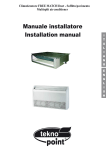
,QVWDOODWLRQ0DQXDO
Use suitable instruments for the refrigerant R410A.
Do not use any other refrigerant than R410A.
Do not use mineral oils to clean the unit.
INSTALLATION DIMENSION DIAGRAM
The installation must be done by trained and qualified service personnel
with reliability according to this manual.
Contact service center before installation to avoid the malfunction due to
unprofessional installation.
When picking up and moving the units, you must be guided by trained and
qualified person.
Ensure that the recommended space is left around
the a ppliance .
A16CM4H4R18
50cm or more
Space to the cover
30cm or above
(Air inlet side)
30cm or above
Space to the cover
50cm or above
Space to the wall
200cm or above
(Air outlet side)
A16CM4H4R24, A16CM4H4R30
50cm or more
Space to the cover
30cm or above
Space to the cover
30cm or above
(Air inlet side)
50cm or above
Space to the wall
200cm or above
(Air outlet side)
This is just the schematic plan, please refer to the actual product.
,QVWDOODWLRQ0DQXDO
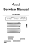
(OHFWULFDO&RQQHFWLRQV
A16CM4H4R18
1. Remove the handle at the right side plate of the
outdoor unit (six screw).
A16CM4H4R18
2. Remove the cable clamp, connect the connection cable and power cable
with the terminal at the row of connection and fix.
the connection. The fitting line distributing must be
consistent with the indoor unit. terminal of line bank.
Wiring should meet that of indoor unit.
3. Fix power connection wire by wire clamp.
Front
side plate
To unit A
4. Ensure wire has been fixed well.
5. Install the handle.
L1 L2
connecting
cable
power
cable
An all-pole disconnection switch having a contact
separation of at least 3mm in all pole should be
connected in fixed wiring.
Wrong wire connection may cause malfunction of some
electric components.After fixing cable, ensure that
leads between connection to fixed point have some space.
To unit B
connecting
cable
To the power supply
L1
L2
L2
L1
The connection pipes and the connectiong wirings of
the unit A and unit B must be corresponding to each
other respective.
The appliance shall be installed in accordance with
national wiring regulations.
Note: the above figures are only intended to be a simple
diagram of the appliance and may not correspond to the
appearance of the units that have been purchased.
All power cables and connection cables must be protected with conduits.
,QVWDOODWLRQ0DQXDO
A16CM4H4R24
1. Remove the handle at the right side plate of the
outdoor unit (ten screw).
2. Remove the cable clamp, connect the connection cable
and power cable with the terminal at the row of connection
and fix the connection. The fitting line distributing must be
consistent with the indoor unit. terminal of line bank.
To unit A
Wiring should meet that of indoor unit.
To unit B
To unit C
L1 L2
3. Fix power connection wire by wire clamp.
4. Ensure wire has been fixed well.
5. Install the handle.
connection
cable
power
cable
connection
cable
connection
cable
To the power supply
An all-pole disconnection switch having a contact
separation of at least 3mm in all pole should be
Outdoor unit
L1 L2
L1
L2
connected in fixed wiring.
Wrong wire connection may cause malfunction of some
electric components.After fixing cable, ensure that
leads between connection to fixed point have some space.
Indoor unit
N(1)
2 3
A
The connection pipes and the connectiong wirings of
the unit A ,unit B and unit C must be corresponding to each
other respective.
N(1)
2 3
N(1)
2 3
C
B
connection cable C
B
The appliance shall be installed in accordance with
national wiring regulations.
connection cable
connection cable A
Do not install the outdoor unit where it is exposed
to the sunlight.
Note:the above figure are only intended to be a simple
diagram of the appliance and may not correspond to the
appearance of the units that have been purchased.
Power cable
1)
The power cable should be put in from the hole under
connection cable cover.
2)
If connecting with two indoor units, the connection cable
should be put in from hole A and hole B.
3)
If connecting with three indoor units, the connection cable
should be put in from hole A , B and C.
4)
If connecting with four indoor units, the connection cable
should be put in from hole A, B , C and D.
All power cables and connection cables must be protected with conduits.
,QVWDOODWLRQ0DQXDO
A16CM4H4R30
D connection cable
1. Remove the handle at the right side plate of the
connection cable C
outdoor unit (ten screw).
2. Remove the cable clamp, connect the connection cable and
power cable with the terminal at the row of connection and fix
the connection. The fitting line distributing must be consistent
with the indoor unit, terminal of line bank.
Wiring should meet that of indoor unit.
B
connection cable
connection cable A
3. Fix power connection wire by wire clamp.
4. Ensure wire has been fixed well.
5. Install the handle.
An all-pole disconnection switch having a contact
separation of at least 3mm in all pole should be
connected in fixed wiring.
Power cable
1)
Wrong wire connection may cause malfunction of some
electric components.After fixing cable, ensure that
2)
leads between connection to fixed point have some space.
The connect ion pipe s and the connectiong wirings of
the unit A ,unit B,unit C and unit D must be corresponding
to each other respective.
3)
4)
The appliance shall be installed in accordance with
national wiring regulations.
The power cable should be put in from the hole under
connection cable cover.
If connecting with two indoor units, the connection cable
should be put in from hole A and hole B
If connecting with three indoor units, the connection cable
should be put in from hole A , B and C
If connecting with four indoor units, the connection cable
should be put in from hole A, B , C and D.
All power cables and connection cables must be protected with
conduits.
Do not install the outdoor unit where it is exposed
to the sunlight.
To unit B
To unit A
To unit D
To unit C
L1 L2
power
cable
connection
cable
connection
cable
connection
cable
connection
cable
To the power supply
L1 L2
Outdoor unit
L1
L2
Indoor unit
N(1) 2
3
N(1) 2
A
B
3
N(1) 2
C
3
N(1) 2
3
D
HANDLING
After having removed the packaging, check that the
contents are intact and complete.
The outdoor unit must always be kept up right.
Handling must be done by suitablye quipped qualified
technical personnel using equipment that is suitable for
the weight of the appliance.
,QVWDOODWLRQ0DQXDO
&KHFN$IWHU,QVWDOODWLRQ
Check Items
Problems Owing to Improper Installation
Is the installation reliable?
The unit may drop, vibrate or make noises
Has the gas leakage been checked?
May cause unsatisfactory cooling (heating)
effect
Is the thermal insulation of the unit
May cause condensation and water dropping
sufficient?
Is the drainage smooth?
May cause condensation and water dropping
Does the power supply voltage accord
The unit may bread down or the components
with the rated voltage specified on the
may be burned out
nameplate?
Are the lines and pipelines correctly
The unit may bread down or the components
installed?
may be burned out
Has the unit been safely grounded?
Risk of electrical leakage.
Are the models of lines in conformity
The unit may bread down or the components
with requirements?
may be burned out
Are there any obstacles near the air
The unit may bread down or the components
inlet and outlet of the indoor and outdoor
may be burned out
units?
Have the length of refrigerating pipe
It is not easy to decide the charge amount
and refrigerant charge amount been
of refrigerant.
recorded?
([SORGHG9LHZVDQG3DUWVOLVW
([SORGHG9LHZVDQG3DUWV/LVW
A16CM4H4R18
22
21
19
20
23
24
18
17
25
16
15
14
26
27
13
12
11
10
9
1
2
3
4
5
6
7
8
([SORGHG9LHZVDQG3DUWVOLVW
'HVFULSWLRQ
12
3URGXFWFRGH
)URQW*ULOO
4W\
&%:
&DELQHW
3
&KDVVLV6XEDVV\
3
'UDLQDJH-RLQW
&RPSUHVVRU*DVNHW
&RPSUHVVRUDQG¿WWLQJV
0DJQHW&RLO
ZD\9DOYH$VV\
7HPSHUDWXUH6HQVRU
7HPSHUDWXUH6HQVRU
&XWRII9DOYH
&XWRII9DOYH
%ORFN
+DQGOH$VV\
(OHFWULFH[SDQGYDOYH¿WWLQJ
(OHFWULFH[SDQGYDOYH¿WWLQJ
3)&,QGXFWDQFH
&ODSERDUG6XE$VV\
7HPSHUDWXUH6HQVRU
5HDU*ULOO
&RQGHQVHU$VV\
7RS&RYHU
3
0RWRU6XSSRUW6XE$VV\
/HIW6LGH3ODWH
3
(OHFWULF%R[$VV\
)DQ0RWRU
$[LDO)ORZ)DQ
7KHGDWDDERYHDUHVXEMHFWWRFKDQJHZLWKRXWQRWLFH
3DUW&RGH
A16CM4H4R18
3
([SORGHG9LHZVDQG3DUWVOLVW
A16CM4H4R24
35
34
33
32
31
30
28
29
27
26
36
25
37
38
39
24
23
22
40
21
20
19
18
17
16
15
1
2
3
4
5
6
7
8
9
10
11
12
13
14
Exploded Views and Parts list
Description
NO.
Product code
1
Front Grill
2
Cabinet
3
Drainage Plug
4
Chassis Sub-assy
5
Drainage Connecter
Qty
CB228W01700
01473049
1
01433047P
1
06813401
3
01203942P
1
06123401
1
6
Compressor and Fittings
00105036
1
7
Compressor Gasket
76710207
3
8
Gas-liquid Separator Assy
07225017
1
9
Inhalation Tube
03723455
1
10
Right Side Plate
0130319401P
1
11
Valve Support Assy
0710306603
1
12
Cut off Valve
07130239
1
13
Cut off Valve
07133185
1
14
big handle Assy
02113043
1
15
Terminal cover Sub-Assy
01253057
1
16
Temperature Sensor
39000073
1
17
Temperature Sensor
3900007301
1
18
Temperature Sensor
3900007302
1
19
Electric Expand Valve Fitting
4300008402
1
20
Electronic Expansion Valve assy
07133456
1
21
Electric Expand Valve Fitting
43000084
1
22
Electric Expand Valve Fitting
4300008401
1
23
Magnet Coil
4300040033
1
24
4-Way Valve Assy
03123415
1
25
Wiring clamp
26115004
1
26
PFC 电感
43120129
1
27
Clapboard Assy
01233420
1
28
Temperature Sensor
3900030901
1
29
Rear Grill
01473043
1
30
Condenser Assy
01113710
1
31
Top Cover
01255005P
1
32
Motor Support Sub-Assy
0170512001
1
33
Condenser Support Plate
01173415
1
34
Left Side Plate
01305041P
1
35
Left Handle
26235401
1
36
Electric Box (Fireproofing)
01413148
1
37
Electric Box Assy
0260370301
1
38
Tube Connector Sub-assy
39
Fan Motor
40
Axial Flow Fan
The data above are subject to change without notice.
26
Part Code
A16CM4H4R24
06643008
2
1501506304
1
10335008
1
([SORGHG9LHZVDQG3DUWVOLVW
A16CM4H4R30
36
35
34
33
32
31
29
30
28
27
37
26
38
25
24
39
40
23
41
1
22
21
20
19
18
17
16
15
2
3
4
5
6
7
8
9
10
11
12
13
14
([SORGHG9LHZVDQG3DUWVOLVW
'HVFULSWLRQ
12
3URGXFWFRGH
)URQW*ULOO
&DELQHW
'UDLQDJH3OXJ
&KDVVLV6XEDVV\
'UDLQDJH&RQQHFWHU
4W\
&%:
3
3
&RPSUHVVRUDQG)LWWLQJV
&RPSUHVVRU*DVNHW
*DVOLTXLG6HSDUDWRU$VV\
,QKDODWLRQ7XEH
5LJKW6LGH3ODWH
3
9DOYH6XSSRUW$VV\
&XWRII9DOYH
&XWRII9DOYH
7HUPLQDOFRYHU6XE$VV\
7HPSHUDWXUH6HQVRU
7HPSHUDWXUH6HQVRU
7HPSHUDWXUH6HQVRU
7HPSHUDWXUH6HQVRU
ELJKDQGOH$VV\
(OHFWULF([SDQG9DOYH)LWWLQJ
(OHFWULF([SDQG9DOYH)LWWLQJ
(OHFWULF([SDQG9DOYH)LWWLQJ
(OHFWULF([SDQG9DOYH)LWWLQJ
0DJQHW&RLO
:D\9DOYH$VV\
:LULQJFODPS
3)& ⬉ᛳ
&ODSERDUG$VV\
7HPSHUDWXUH6HQVRU
5HDU*ULOO
&RQGHQVHU$VV\
7RS&RYHU
3
0RWRU6XSSRUW6XE$VV\
&RQGHQVHU6XSSRUW3ODWH
/HIW6LGH3ODWH
3
/HIW+DQGOH
(OHFWULF%R[)LUHSURR¿QJ
(OHFWULF%R[$VV\
7XEH&RQQHFWRU6XEDVV\
)DQ0RWRU
$[LDO)ORZ)DQ
7KHGDWDDERYHDUHVXEMHFWWRFKDQJHZLWKRXWQRWLFH
3DUW&RGH
A16CM4H4R30
7URXEOHVKRRWLQJ
7URXEOHVKRRWLQJ
0DOIXQFWLRQ,QGLFDWRU
Note:
○: off
●: on
Ƽ: blink
When several malfunctions occur at the same time, they will be displayed in circulation and every malfunction is
displayed for 5s.
NO
0
Malfunction description
Normal stop
1
2
Compressor run
Compressor overload protection
3
4
5
6
7
8
9
Discharge protection
Outdoor unit overload protection
High pressure protection
Over current protection
IMP protection
IMP over heating protection
PFC protection (including PFC overheating protection)
10
11
12
13
14
15
Phase current protection
Over voltage protection
Insufficient voltage protection
Start failure
Compressor desynchronizing
Compressor phase-lacking protection
16
Compressor phase current detection malfunction
17
18
19
20
21
22
23
24
Memory chip mistake
DC power supply circuit-short
Defrosting
Oil return
Complete unit frequency restriction protection
Complete unit frequency dropping protection
Unit A frequency restriction or frequency dropping protection
Unit B frequency restriction or frequency dropping protection
25
26
27
28
29
30
31
Unit C frequency restriction or frequency dropping protection
Unit D frequency restriction or frequency dropping protection
Outdoor ambient temperature sensor protection
Outdoor tube temperature sensor protection
Discharge temperature sensor protection
IPM thermal resistance malfunction
Unit A liquid pipe temperature sensor malfunction
32
33
34
Unit A gas pipe temperature sensor malfunction
Unit B liquid pipe temperature sensor malfunction
Unit B gas pipe temperature sensor malfunction
35
36
Unit C liquid pipe temperature sensor malfunction
Unit C gas pipe temperature sensor malfunction
37
38
39
Unit D liquid pipe temperature sensor malfunction
Unit D gas pipe temperature sensor malfunction
Unit A mode conflict
40
Unit B mode conflict
41
42
Unit C mode conflict
Unit D mode conflict
LED1
LED2
LED3
LED4
○
●
○
○
○
●
●
●
○
○
○
○
○
○
○
○
○
●
●
●
●
●
●
●
●
●
○
○
○
○
○
○
○
○
○
○
○
○
○
○
○
○
○
○
○
○
○
○
○
○
○
○
○
●
●
●
●
●
●
●
●
●
●
●
●
●
●
●
●
Ƽ
○
●
Ƽ
○
●
Ƽ
○
●
Ƽ
○
●
Ƽ
Ƽ
Ƽ
Ƽ
○
○
○
●
●
●
○
●
Ƽ
Ƽ
Ƽ
○
●
○
○
○
●
●
●
Ƽ
Ƽ
Ƽ
Ƽ
Ƽ
Ƽ
Ƽ
Ƽ
Ƽ
Ƽ
Ƽ
Ƽ
Ƽ
Ƽ
○
○
○
●
●
●
○
●
Ƽ
Ƽ
Ƽ
Ƽ
○
●
Ƽ
○
○
○
●
●
●
○
Ƽ
○
○
○
○
○
○
○
○
○
●
●
●
●
●
●
●
Ƽ
○
●
Ƽ
○
●
Ƽ
○
●
Ƽ
○
●
Ƽ
○
●
7URXEOHVKRRWLQJ
43
Communication failure with Unit A
●
Ƽ
44
45
46
47
48
49
50
51
52
Communication failure with Unit B
Communication failure with Unit C
Communication failure with Unit D
Unit A freeze protection
Unit B freeze protection
Unit C freeze protection
Unit D freeze protection
Unit A overheating prevention protection
Unit B overheating prevention protection
Ƽ
Ƽ
○
●
Ƽ
○
○
○
●
●
●
○
●
Ƽ
Ƽ
Ƽ
Ƽ
Ƽ
Ƽ
Ƽ
Ƽ
Ƽ
Ƽ
53
54
55
56
57
58
Unit C overheating prevention protection
Unit D overheating prevention protection
Unit A communication wire misconnection or expansion valve malfunction
Unit B communication wire misconnection or expansion valve malfunction
Unit C communication wire misconnection or expansion valve malfunction
Unit D communication wire misconnection or expansion valve malfunction
Ƽ
Ƽ
Ƽ
●
●
●
●
●
●
●
●
●
●
●
○
●
○
○
○
●
●
○
○
○
○
○
Ƽ
Ƽ
Ƽ
Ƽ
Ƽ
Ƽ
○
●
Ƽ
○
●
●
●
0DOIXQFWLRQ&KHFNLQJDQG(OLPLQDWLRQ
Note: discharge the position in below pictures with discharge resistance after open the top cover and
check if the voltage is below 20V with universal meter, then begin to check.
18K:
24/30K:
(1) IPM protection malfunction:
Main checking point:
●
If the input voltage of the unit is within normal range?
●
If the connection wire of compressor is connected well? Is it loose? If the connection sequence is correct?
●
If the resistance of compressor coil is normal? If the isolation of compressor coil with copper pipe is good?
●
If the unit is overloaded? If the heat radiation of the unit is good?
●
If the refrigerant charge is suitable?
Flow chart:
7URXEOHVKRRWLQJ
Energize the unit
Please check:
1. if the indoor and outdoor heat exchanges are
dirty, if there is obstacle to affect the radiation;
2. if the indoor and outdoor fans are running
normally;
3. if the pressure of the system is too high;
4. if the refrigerant is too much which causes
the high level of pressure;
yes
If the above cases are existed?
no
Correct according to the service
manual and then energize the
unit to operate
no
If the wire of compressor is connected
well and correctly?
yes
Reconnect the wire of the
compressor according to the
correct wiring method
Test the resistance between
the three phases
no
If the resistance is normal?
yes
Test the isolation impedance
between the three phases of the
compressor and thecopper pipe
yes
If the resistance is above 500M
?
no
Replace the
compressor
yes
Malfunction is eliminated
no
Replace the outdoor
mainboard
End
7URXEOHVKRRWLQJ
(2) PFC protection malfunction
Main checking points:
● If the power supply is normal;
● Check if the connection wire of induction is connected well and if the induction is broken;
Flow chart:
Start
Check If the power supply is normal
Turn on the unit after the
yes
power supply resumes to
Power supply is abnormal
normal situation
no
Check if the outdoor induction is broken
yes
The induction is broken
Replace the induction
no
no
Malfunction is eliminated
Replace the outdoor
mainboard
yes
End
7URXEOHVKRRWLQJ
(3) Capacity charging malfunction
Main checking points:
● If the wiring of the induction is connected well and if the induction is broken;
● If the mainboard is broken;
Flow chart:
Energize the unit and wait
for 1min
Test the voltage between the two
ends of the electrolytic capacitor
with the DC shift of the universal
meter
yes
The voltage is above 100V
The detection circuit of
the outdoor mainboard
has malfunction
Replace the outdoor mainboard
no
Check if the induction wiring is loose
or the induction is cut off
The induction is cut off or the
wiring is loose
yes
Replace the induction or
reconnect the loose wire
Malfunction is eliminated
yes
no
no
Replace the outdoor
mainboard
End
7URXEOHVKRRWLQJ
(4) Anti-high temperature and overload malfunction
Main checking points:
● If the outdoor ambient temperature is within the normal range;
● If the outdoor fan is running normally;
● If the indoor and outdoor radiation environment is good;
Flow chart:
Start
yes
If the outdoor ambient temperature
is above 53 ć
It is a normal protection, please
operate the unit after the outdoor
ambient temperature has changed
no
yes
Improve the radiation
environment of the unit
no
Check if the terminal of the fan is
connected well, if the fan is broken
If the indoor and outdoor radiation
is insufficient
no
If the outdoor fan is working normally
yes
Replace fan capacitor
Replace outdoor
mainboard
Replace outdoor fan
End
7URXEOHVKRRWLQJ
(5) Temperature sensor malfunction
Main checking points:
ƽ If the temperature; sensor is damaged or broken
ƽIf the terminal of the temperature sensor is loosended or not connected;
ƽIf the mainboard is broken;
Flow chart:
Start
Check whether the wiring terminal between
temperature sensor and controller is loosened or poorly
yes
contacted?
Insert the temperature
sensor tightly
no
no
Check whether the
temperature senspr is normal according to
Eliminate the
malfunction
no
yes
Replace the temperature sensor
with the same model
resistance table
no
yes
yes
Eliminate the malfunction
Replace the controller with
the same model
End
7URXEOHVKRRWLQJ
(6) Start failure malfunction
Main checking points:
ƽ If the connection wire of the compressor is connected properly;
ƽIf the stop duration of the compressor is sufficient;
ƽIf the compressor is broken;
ƽIf the
; refrigerant charging amount is too much;
Flow chart:
Energize and
start the unit
no
If the stop duration of the compressor
is longer than 3min
yes
If the connection wire of the compressor
is connected well and correctly
yes
no
no
If the refrigerant charging
amount is too much
Charge the refrigerant
according to the
service manual
yes
Eliminate the malfunction
no
not enough, the high and low
pressure of the system is not
balanced, restart it after 3min
Replace the outdoor
mainboard
yes
Eliminate the malfunction
no
Replace the compressor
End
Eliminate the malfunction
yes
yes
The stop duration of the unit is
Reconnect the connection wire
of the compressor according
to the wiring diagram
no
7URXEOHVKRRWLQJ
(7) Communication malfunction
Main checking points:
ƽ If the connection wire between the indoor unit and outdoor unit is connected well, if the wires inside the unit is connected well;
ƽIf the indoor mainboard or outdoor main board is broken;
Flow chart:
Communication malfunction of some
indoor units
De-energize,check the connection
wire of indoor and outdoor unit and
the wire of the eletric box is
connected correctly
Connected correctly
no
Reconnect according to
the wiring diagram
yes
Eliminate the malfunction
no
yes
De-energize, change the communication wire of the wellcommunicated indoor unit and malfunction indoor unit,
then energize the unit and wait for 3min
The malfunction indoor unit
resumes normal
yes
Replace outdoor
mainboard
no
Replace the mainboard of the
malfunction indoor unit
End
7URXEOHVKRRWLQJ
All the indoor units appear
communication malfunction
De-energize,check the connection
wire of indoor and outdoor unit and
the wire of the eletric box is
connected correctly
no
Reconnect according to
Connected correctly?
yes
Eliminate the malfunction
the wiring diagram
yes
De-energize, check if the connection wire between
the outdoor mainboard and the filter board
according to the wiring diagram
Reconnect according to
the wiring diagram
no
Connected correctly?
yes
Eliminate the malfunction
no
yes
yes
The connection wire is broken?
Replace the
connection wire
yes
Eliminate the malfunction
no
no
Check if there is power input
bewtween the netrual wire and live
wire of the outdoor mainboard
no
There is power input?
Replace the filter board of
the outdoor unit
no
yes
Replace the outdoor
mainboard
Resume communication?
yes
End
yes
Eliminate the malfunction
no
Replace indoor
mainboard
7URXEOHVKRRWLQJ
(8) Compressor overload, diacharge protection malfunction
Main checking points:
ƽ If the eletric expansion valve is connected well or it is broken;
ƽIf there is refrigerant leakage;
ƽIf the overload protector is broken;
Flow chart:
Start
If the overload protector is connected well?
no
yes
no
Check the resistance between the two
ends of the overload protector in ambient temperature,
if the resistance is below 1k
yes
If the wiring of the eletric expansion valve
is coonected well?
Replace the
overload
protector
no
Reconnect according
to the wiring diagram
Check the coil of the eletric
expansion valve, replace
it if it is broken
Eliminate the malfunction
yes
no
Check the refrigerant status, if there is
refrigerant leakage, recharge it according
to the service manual
yes
Eliminate the malfunction
no
Replace outdoor
mainboard
End
Noted: the detection method of the coil of the eletric expansion valve: there is five pieces of the coil of the eletric expansion valve,
the resistance of one of them (the leftmost or the rightmost one) is almost the same as the resistance of other terminal (within
100
). Judge the condition of the electronic expansion valve through detecting these resistance.
7URXEOHVKRRWLQJ
(9) Compressor desynchronizing malfunction
Main checking points:
ƽ If the pressure of the system is too high;
ƽIf the eletric expansion valve is working normally or it is broken;
ƽIf the radiation of the unit is good;
Flow chart:
The unit appears desynchronizing
as soon as energizing and starting
no
The stop duration of the compressor is longer
than 3min?
yes
The wiring of the compressor is
no
Reconnect the wire properly
connected properly?
yes
no
yes
Eliminate the malfunction
no
Replace the eletric
expansion valve
The eletric expansion valve is broken?
yes
no
yes
Eliminate the malfunction
Replace outdoor mainboard
yes
Eliminate the malfunction
no
Replace the compressor
End
7URXEOHVKRRWLQJ
$SSHQGL[5HVLVWDQFH7DEOHRI$PELHQW7HPSHUDWXUH6HQVRUIRU,QGRRUDQG2XWGRRU8QLWV.
7HPSć 5HVLVWDQFHNȍ
7HPSć 5HVLVWDQFHNȍ
7HPSć 5HVLVWDQFHNȍ
7HPSć 5HVLVWDQFHNȍ
7URXEOHVKRRWLQJ
$SSHQGL[5HVLVWDQFH7DEOHRI2XWGRRUDQG,QGRRU7XEH7HPSHUDWXUH6HQVRUV.
7HPSć 5HVLVWDQFHNȍ
7HPSć 5HVLVWDQFHNȍ
7HPSć 5HVLVWDQFHNȍ
7HPSć 5HVLVWDQFHNȍ
7URXEOHVKRRWLQJ
$SSHQGL[5HVLVWDQFH7DEOHIRU2XWGRRU'LVFKDUJH7HPSHUDWXUH6HQVRU.
7HPSć 5HVLVWDQFHNȍ
7HPSć 5HVLVWDQFHNȍ
7HPSć 5HVLVWDQFHNȍ
7HPSć 5HVLVWDQFHNȍ
1RWH7KHLQIRUPDWLRQDERYHLVIRUUHIHUHQFHRQO\
5HPRYDO3URFHGXUH
5HPRYDO3URFHGXUH
5HPRYDO3URFHGXUH.
:DUQLQJ%HVXUHWRZDLWIRUDPLQLPXPRIPLQXWHVDIWHU
WXUQLQJRIIDOOSRZHUVXSSOLHVEHIRUHGLVDVVHPEO\
3URFHGXUH
6WHSV
5HPRYHWRSFRYHUDQGKDQGOH
%HIRUHGLVDVVHPEO\
7ZLVWRIIWKHVFUHZVXVHGIRU¿[LQJWKHKDQGOHSXOO
WKHKDQGOHXSZDUGWRUHPRYHLW
+DQGOH
7RSSDQHO
7ZLVW RII WKH VFUHZV XVHG IRU ¿[LQJ WKH WRS FRYHU
SXOOWKHWRSFRYHUXSZDUGWRUHPRYHLW
5HPRYDO3URFHGXUH
3URFHGXUH
6WHSV
5HPRYHIURQWJULOOHDQGIURQWSDQHO
5HPRYH WKH VFUHZV FRQQHFWLQJ WKH IURQW JULOOH
DQGWKHIURQWSDQHO5HPRYHWKHIURQWJULOOH
)URQWJULOOH
7ZLVW RII WKH VFUHZV IL[LQJ WKH SDQHO SXOO LW
XSZDUGORRVHQWKHFODVSRQWKHULJKWVLGHURWDWH
LWWRWKHOHIWDQGWKHQUHPRYHWKHIURQWSDQHO
)URQWSDQHO
5HPRYHULJKWVLGHSODWH
5HPRYH WKH VFUHZV FRQQHFWLQJ WKH ULJKW VLGH
SODWHZLWKWKHFKDVVLVWKHYDOYHVXSSRUWDQGWKH
HOHFWULFER[DQGWKHQUHPRYHWKHULJKWVLGHSODWH
DVV\
ULJKWVLGH
SODWH
5HPRYHWKHVFUHZVFRQQHFWLQJWKHOHIWVLGHSOD
WHDQGWKHFKDVVLVDQGWKHQUHPRYHWKHOHIWVLGH
SODWHDVV\
/HIW6LGH3ODWH
5HPRYDO3URFHGXUH
3URFHGXUH
6WHSV
5HPRYHWKHD[LDOÀRZIDQ
5HPRYH WKH QXWV ¿[LQJ WKH EODGH DQG WKHQUHPRYH
WKHD[LDOÀRZIDQ
$[LDO)ORZ)DQ
5HPRYHWKHWDSSLQJVFUHZV¿[LQJWKHPRWRUGLV
FRQQHFWWKHOHDGLQJZLUHLQVHUWRIWKHPRWRUDQGWKHQ
UHPRYHWKHPRWRU5HPRYHWKHWDSSLQJVFUHZV
¿[LQJWKHPRWRUVXSSRUWDQGWKHQSXOOWKHPRWRUVXS
SRUWXSZDUGVWRUHPRYHLW
IDQPRWRU
¿[LQJIUDPH
IDQPRWRU
5HPRYH(OHFWULF%R[$VV\
5HPRYHWKHVFUHZV¿[LQJWKHHOHFWULFER[VXEDVV\
ORRVHQWKHZLUHEXQGOHSXOORXWWKHZLULQJWHUPLQDOV
DQGWKHQSXOOWKHHOHFWULFER[XSZDUGVWRUHPRYHLW
(OHFWULF%R[
5HPRYDO3URFHGXUH
3URFHGXUH
6WHSV
5HPRYHVRXQGSURRIVSRQJH
7HDUXSWKHVRXQGSURRIVSRQJHFDUHIXOO\
6RXQGSURRI
VSRQJH
5HPRYHUHDFWRU
5HPRYH VFUHZV FRQQHFWLQJ UHDFWRU DQG PLGGOH
LVRODWLRQVKHHWDQGWKHQUHPRYHWKHUHDFWRU
UHDFWRU
5HPRYHZD\YDOYH
ZD\
'LVFKDUJH WKH UHIULJHUDQW FRPSOHWHO\XQVROGHU
YDOYH
WKH SLSHOLQHV FRQQHFWLQJ WKH FRPSUHVVRU DQG WKH
FRQGHQVHUDVV\DQGWKHQUHPRYHWKHZD\YDOYH
DVV\
5HPRYDO3URFHGXUH
3URFHGXUH
6WHSV
5HPRYHHOHFWURQLFH[SDQVLRQYDOYHDQGFXWRIIYDOYH
HOHFWURQLFH[SDQVLRQYDOYH
5HPRYH HOHFWURQLF H[SDQVLRQ YDOYH DQG FXWRII
YDOYH 8QVROGHU WKH VSRW ZHOG EHWZHHQ HOHFWURQLF
H[SDQVLRQ YDOYH DQG FXWRII YDOYH DV ZHOO DV WKH
VSRW ZHOG RI FRQQHFWLRQ SLSH IRU FRQGHQVHU DQG
WKHQ UHPRYH WKH H[SDQVLRQ YDOYH 0HDQZKLOH
URWDWH RXW WKH HOHFWURQLF FRLO DQG WKHQ SXOO LW
FXWRIIYDOYH
XSZDUGVWRUHPRYHLW
5HPRYHYDOYHVXSSRUWVXEDVV\
5HPRYHVFUHZV¿[LQJYDOYHVXSSRUWDQGFKDVVLV
DQGWKHQUHPRYHWKHYDOYHVXSSRUWVXEDVV\
YDOYHVXSSRUW
VXEDVV\
5HPRYHLVRODWLRQVKHHW
5HPRYH VFUHZV IL[LQJ LVRODWLRQ VKHHW DQG WKHQ
UHPRYHWKHLVRODWLRQVKHHW
LVRODWLRQVKHHW