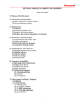
1
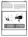
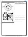
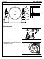
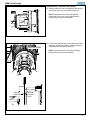
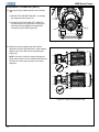
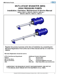
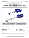
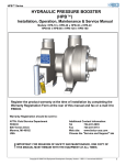
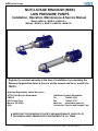
MSB Series Pumps
MUTLI-STAGE BRACKISH (MSB)
LOW PRESSURE PUMPS
Installation, Operation, Maintenance & Service Manual
Models: MSB-15 ● MSB-20 ● MSB-30 ●
MSB-40 ● MSB-55 ● MSB-75 ● MSB-90 ● MSB-120
Register the product warranty at the time of installation by completing the
Warranty Registration Form at the rear of this manual and fax or e-mail it to
FEDCO.
Warranty Registration should be sent to:
ATTN: Field Service Department
Additional Contact Information:
FEDCOTel734-241-3935
800 Ternes DriveFax734-241-5173
Monroe, MI 48162 Web site: www.fedco-usa.com
USAChoose the "Service and Support" tab
!
IMPORTANT: FOR REASONS OF SAFETY AND MAINTENANCE, ONE COPY OF
THIS MANUAL MUST REMAIN WITH THE EQUIPMENT AT ALL TIMES.
Copyright © 2009 Fluid Equipment Development Company Version – MSB 1.1 Last revised: 04/2012
1
MSB Series Pumps
Table of Contents
Theory and Operation ............................... ....... 3 Basic Troubleshooting ............................. 27
MSB Pump External Components ................. 3
Visual Inspection ................................... 27
Troubleshooting Chart .......................... 28
MSB Pump Internal Components .................. 4
Installation Procedures ..................................... 5 Shaft Seal Replacement ......................... 29
Warnings and Safety Precautions ....... .......... 5 Balance Disc Replacement .................... 35
User Health and Safety .................................. 6 Specifications .......................................... 43
In The Work Area ........................................... 6
Components Exploded Views .............. 43
Electrical Connections and Regulations ..... ... 6
Recommended Spare Parts List .......... 44
Variable Frequency Drive (VFD)
Service Parts Kits ................................. 44
Requirements .............................................. 7
Ordering Parts ..................................... 45
Inspection of Unit upon Receipt ..................... 7
Fastener Specifications ....................... 46
Pump Storage Requirements ......................... 7
Balance Disc Specifications ................ 46
Motor Storage Requirements ......................... 7
Lubricants and Compounds ................. 46
Pre-Installation ............................................... 7
Maintenance ........................................ 47
Lifting and Handling ....................................... 9 Service Policy .......................................... 48
Optional Baseplate Installation ..................... 11
Return Authorization Number (RAN ..... 48
Foundation Specifications ..............................11
Warranty ........................................ ...... 49
Motor Installation ............................................12
Warranty Registration Form ........ ........ 50
Start Up Record ............................... .... 51
Flexible Coupling Check ............................... 13
Initial Pump Alignment ..................................... 16
Overhaul Record .................................. 52
Final Pump Alignment ................................... 20 Pump Piping Connections ............................. 24
Recommended Instrumentation
and Operation ............................................ 25
Upstream Filtration ........................................ 26
Preparation for Pump Start Up ........................ 26
Start Up Precautions ....................................... 26
Start Up Check List ...................................... 26
Pump Start Up ........................................... ... 26
2
Copyright © 2009 Fluid Equipment Development Company Version – MSB 1.1 Last revised: 04/2012
MSB Series Pumps
Theory and Operation
MSB Pump External Components
Multi-stage brackish (MSB) pumps are centrifugal feed
pumps specifically designed to supply high pressure
pumps for brackish water reverse osmosis (BWRO) service. MSB pumps develop pressure by using a series of
impellers mounted on a rotating shaft. Rotating this fluid
through centrifugal force develops a pressure higher
than was input. Pressure can be increased through the
addition of impeller stages or by increasing shaft rpm.
Motors are selected according to equipment operating requirements (Figure 1). A flexible coupling allows the pump
shaft to float within the coupling eliminating thrust against
the motor. The inlet and discharge housing is designed to
connect to grooved rigid piping with couplings. The inlet
housing itself can be attached to the pump in four different
positions 90°apart. A precision leveling foot supports the
end shell housing and is fully adjustable to allow accurate
pump-to-motor shaft alignment.
Typical MSB-15/MSB-120 Pump External Components
3
1
2
4
5
6
7
8
Item
Description
Item
Description
1
Motor
5
Top cradle
2
Motor adapter
6
Discharge housing
3
Inlet Housing
7
Precision leveling foot
4
End shell housing
8
Flexible coupling (inside of Motor Adapter
Figure 1 MSB Pump External Components
Copyright © 2009 Fluid Equipment Development Company Version – MSB 1.1 Last revised: 04/2012
3
MSB Series Pumps
Theory and Operation (cont.)
MSB Pump Internal Components
The internal components of an MSB pump consist of a
number of stages. The basic components contained in a
single stage consist of an impeller and a diffuser with a
split cone and bushing which prevent friction and wear.
Behind the discharge housing at the end of the pump
is the WATER BEARING™ assembly. (Figure 2). The
balance disc rides in the bearing carrier and serves as
a thrust bearing for the pump. This unique design uses
patented WATER BEARING™ technology which allows
feed water to cool and lubricate the balance disc.
INLET
PRESSURE
SINGLE
STAGE
As the motor rotates the pump, pressure differences
acting on the rotating impellers generate an axial
thrust acting toward the motor. The water bearing
employs the balance disc to create a counter-pressure which exactly cancels the impeller thrust load.
The internal throttle nipple is used help produce the
counter-pressure on the balance disc. This thrust and
counter-thrust allows the disc to "self-balance" based
on operating conditions.
WATER BEARING™
ASSEMBLY
DISCHARGE
PRESSURE
Figure 2 MSB Pump Internal Flow
4
Copyright © 2009 Fluid Equipment Development Company Version – MSB 1.1 Last revised: 04/2012
MSB Series Pumps
Installation Procedures
Warnings and Safety Precautions
Safety practices and precautions for the operation and
maintenance of all FEDCO pump products MUST BE
FOLLOWED. This information supplements oral or written
instructions that may be received. Safety MUST be practiced as part of the standard operating procedures for this
equipment during any installation and operation. To ensure
that safe operating and maintenance procedures are followed, operators should develop and keep up a program
of safety checks and current instructions. This manual
contains certain operating and maintenance procedures
that involve exposure to potentially hazardous situations.
The levels of hazardous situations are as follows:
DANGER
Hazards which are IMMEDIATELY ACCESSIBLE, and capable
of causing SEVERE PERSONAL INJURY OR DEATH.
WARNING
Hazards which are NOT IMMEDIATELY ACCESSIBLE, but are
capable of causing SEVERE PERSONAL INJURY OR DEATH.
CAUTION
Hazards which are NOT IMMEDIATELY ACCESSIBLE, and can
cause PERSONAL INJURY.
ELECTRICAL
HAZARD
Hazards which are related to Electrical Components and can
RESULT IN ELECTRICAL RISKS, SHOCK, ELECTROCUTION
OR DEATH if instructions are not followed properly.
PUNCTURE
HAZARD
Hazards which are NOT IMMEDIATELY ACCESSIBLE and can
RESULT IN SEVERE PERSONAL INJURY OR DEATH if instructions are not followed properly.
Copyright © 2009 Fluid Equipment Development Company Version – MSB 1.1 Last revised: 04/2012
5
MSB Series Pumps
Installation Procedures (cont.)
WARNING
ELECTRICAL HAZARD
All pump and safety precautions must be followed to
prevent physical injury to the operator. It is illegal to operate the equipment in an EU member state, which requires
CE compliance, if the manual is not written in that state’s
language. If a translation is needed, please contact a
FEDCO representative.
Always follow the Lock-out / Tag-out procedure developed
by your company before starting any maintenance or
repair (Figure 3).
CAUTION
A pump is a pressure-generating device with rotating
parts that can be hazardous. Any device containing
generated pressure can rupture, explode or discharge
its contents if it is sufficiently over-pressurized and may
possibly result in personal injury, property damage, environmental damage and death. All necessary precautions
must be exercised to insure over-pressurization does not
occur. FEDCO will not accept responsibility for physical
injury, damage or delays caused by a failure to observe
the instructions in this manual.
WARNING
Installation, operation or maintenance of the pump unit
in any manner which is not covered in this manual could
cause damage to the equipment, serious injury or death.
This includes any modification to the equipment or the
use of parts not provided by FEDCO. If there is a question regarding the intended use of the equipment, please
contact a FEDCO representative before proceeding.
CAUTION
This manual clearly identifies accepted methods for safe
disassembly. These methods must be strictly adhered to.
WARNING
Do not use the pump equipment for a different application
than originally specified without the approval of a FEDCO
representative.
WARNING
NEVER operate the pump equipment:
● below the minimum flow rate.
● when dry.
● without priming.
● without proper guards and safety devices installed.
● with the discharge valve closed.
● with the suction valve closed.
6
FRONT
BACK
Figure 3 Typical Lock-Out Tags
User Health and Safety
Safety Equipment should be used in accordance with
company regulations. The following safety equipment
should be used within the work area:
• Helmet.
• Safety Glasses with shields or goggles.
• Safety Shoes.
• Protective Gloves.
• Hearing Protection is recommended.
• Follow safe lifting methods to avoid personal injury.
In the Work Area
• Always keep the work area clean and dry.
• Avoid all electrical dangers. Be aware of risks from
electric shock or arc flash hazards.
• Utilize adequate lifting equipment and methods.
Electrical Connections and Regulations
• Refer to the motor nameplate for specific electrical
operating information (Figure 4).
• Electrical connections must be made by certified
electricians in compliance with all international, national,
state, and local regulations and codes.
• Insure the product is isolated from the power supply and
cannot be accidentally energized.
• Make sure all thermal contacts are connected to a
protection circuit according to product specifications.
• All electrical equipment must be properly grounded
(Figure 5).
• During installation, service and repair, must always
follow your company’s Lock-out / Tag-out procedure.
Copyright © 2009 Fluid Equipment Development Company Version – MSB 1.1 Last revised: 04/2012
MSB Series Pumps
Installation Procedures (cont.)
Variable Frequency Drive (VFD) Requirements
A VFD must be used to optimize the system to the best efficiency point (BEP) of the RO system. The VFD must be
configured to match the motor nameplate information. The VFD does not come pre-programed (Figure 4). Please
contact the equipment supplier if the VFD programming manual is not available. Important note for CE compliant countries: the VFD must have a line filter which must be installed in the same metallic enclosure as the drive.
VARIABLE
FREQUENCY
OUTPUT POWER
SINE WAVE
INPUT POWER
HITAKHI
FUNC
1
Hz
POWER
A
ALARM
RUN
STOP/
RESET
RUN
PRG
2
STR
W 200
CONTROL SIGNAL
WARNING
HAZARD OF PERSONAL INJURY
OR ELECTRIC SHOCK
Disconnect incomming power and wait
ten minutes before opening front cover
VARIABLE FREQUENCY
DRIVE (VFD)
Figure 4 Basic VFD Configuration
Inspection of Unit Upon Receipt
•
•
•
Review the contents of the packing list to make sure all components have been included.
Inspect all components for signs of damage which may have occurred during shipping.
If damage is present or if the contents are incomplete, please contact your shipping company or a FEDCO
representative before proceeding.
Pump Storage Requirements
The MSB unit must be protected from moisture, sand, grit, and other foreign matter. Do not remove the protective covers from the pipe connections until ready to install. For long-term storage, keep pump and all other components in its
original crate away from moisture, sand, grit or dust.
Motor Storage Requirements
Specific conditions are required for proper motor care and storage. Refer to the motor manufacturers instructions for
specific steps and instructions.
Pre-Installation
In most instances, the unit and motor are shipped pre-assembled. All necessary installation accessories will be
included with the pump.
Copyright © 2009 Fluid Equipment Development Company Version – MSB 1.1 Last revised: 04/2012
7
MSB Series Pumps
Installation Procedures (cont.)
4 to 8 Motor adapter bolts with washers
4 to 6 Motor mounting bolts with washers
and nuts (if motor and baseplate is provided
by FEDCO)
Feeler Guages
2 Alignment Pins
Flexible coupling
Pump shaft key
E
EIZ
TI-S
AN
2 Flexible coupling set screws
Anit-seize compound
Motor shaft key (if motor is
provided by FEDCO)
Figure 5 Installation Accessories
8
Copyright © 2009 Fluid Equipment Development Company Version – MSB 1.1 Last revised: 04/2012
MSB Series Pumps
Installation Procedures (cont.)
Lifting and Handling
CAUTION
Observe all lifting precautions. Failure to follow all lifting and handling precautions may result in serious injury! Unit weight is listed on the unit nameplate. Determine the weight of the unit to select an appropriate lifting method.
If the weight of the pump exceeds manual lifting limits, mechanical lifting equipment must be used. MSB pumps can
be lifted by the shell using approved lifting straps together with suitable lifting equipment. The straps must be installed
around the shell to properly balance the load and minimize stress on the inlet and motor adapter connections
(Figure 7).
Pump Assembly Lifting
NO
Figure 6 Improper Lifting Strap Positioning
YES
Figure 7 Proper Lifting Strap Positioning
Copyright © 2009 Fluid Equipment Development Company Version – MSB 1.1 Last revised: 04/2012
9
MSB Series Pumps
Installation Procedures (cont.)
CAUTION
Whenever possible, each component should be lifted and moved separately for safety. Do not lift the pump up
by the shaft. If the unit is lifted by the shaft, damage may occur. Lifting and handling of the motor must be performed
according manufacturers instructions. Do not lift the pump and motor by the motor eyebolt (Figure 8). The eyebolt
is used for lifting the motor only.
Motor and Pump Assembly Lifting
NO
NO
Figure 8 Improper Motor and Pump Lifting Points
YES
Figure 9 Proper Motor and Pump Lifting Points
10
Copyright © 2009 Fluid Equipment Development Company Version – MSB 1.1 Last revised: 04/2012
MSB Series Pumps
Installation Procedures (cont.)
Optional Baseplate Installation
Some units include an optional FEDCO baseplate which provides good mounting surfaces for the motor and pump
(Figure 10). It also increases accuracy during the alignment process. Although the baseplate is precisely manufactured,
it requires a solid foundation such as a concrete pad or rigid steel substructure. If the optional baseplate is used, it
must be installed first to avoid distortion which may occur due to uneven floors or substructure (Figure 13). If the pump
is installed within a container, it must be mounted on a rigid steel substructure that will not distort under the weight of
the equipment or from torque reaction forces during pump operation.
1
3
2
4
Item
Descripttion
Item
Description
1
Motor mounting (4 to 6 depending on motor)
3
Precision leveling foot mounting
2
Support bracket mounting
4
Baseplate mounting feet
Figure 10 Optional Baseplate
Foundation Specifications
A concrete foundation is recommended for all MSB pump installations. Concrete provides good support and good
vibration absorption. The foundation should have a mass that is 50% more than the total weight of the equipment and
its perimeter should extend at least 6 inches (15 cm) on each side from the pump and motor. Make sure the concrete
is completely dry and level before installing any machinery. Make sure anchor bolts and shims are properly sized and
installed in cases of uneven surfaces (Figure 11).
OPTIONAL BASEPLATE
LEVELING HOLES
CONCRETE FOUNDATION
PROPER SHIM PLACEMENT
Figure 11 Proper Shimming
Copyright © 2009 Fluid Equipment Development Company Version – MSB 1.1 Last revised: 04/2012
11
MSB Series Pumps
Installation Procedures (cont.)
Motor Installation
1. Clean the motor flange face with a clean cloth to
remove any foreign matter, rust or protective coating
and place the motor in its mounting position.
(Figure 12).
Figure 12 Placing Motor in Mounting Position
2. Install the motor mounting bolts and shims as necessary
(Figure 13). Tighten to motor manufacturers specifications.
NOTE: Make sure to install shims where necessary
to prevent motor frame distortion resulting from "softfoot." Soft-foot is a condition were one of the motor
frame feet are not in flat contact with the mounting base.
If not properly shimmed when the bolt is tightened, the
motor frame will distort.
SOFT-FOOT
NO
PROPERLY
SHIMMED
YES
Figure 13 Installing Motor Mounting Shims
12
Copyright © 2009 Fluid Equipment Development Company Version – MSB 1.1 Last revised: 04/2012
MSB Series Pumps
Installation Procedures (cont.)
Motor Rotational Direction Check
3. Prior to pump installation, energize the motor to
determine the direction of rotation. The correct rotation
is indicated by arrows on the pump motor adapter
(Figure 14). If the rotation is incorrect, reverse the
polarity of the motor wiring to change the direction of
rotation.
NOTE: Reversing polarity of the VFD power input wires
will not change the motor rotational direction.
Figure 14 Directional Arrows on Motor Adapter
4. If the motor rotational direction is correct, disconnect
the power to the motor according to lock-out/tag-out
procedures and complete all electrical connections
according to local codes and regulations.
5. Loosen the eight (8) screws and remove the coupling
guards (Figure 15).
Figure 15 Removing Coupling Guards
Flexible Coupling Check
6. Slide the flexible coupling over the motor shaft with
the motor shaft key (Figure 16).
NOTE: If the motor shaft key does not fit properly in
the coupling keyway, lightly file the motor shaft key
until a proper fit is obtained.
Figure 16 Installing Flexible Coupling on Motor Shaft
Copyright © 2009 Fluid Equipment Development Company Version – MSB 1.1 Last revised: 04/2012
13
MSB Series Pumps
Installation Procedures (cont.)
7. Inspect the flexible coupling radial and axial fit. It
should be tight with no visible radial movement and
slide smoothly on and off the motor shaft (Figure 17).
NO
MOVEMENT
NO
MOVEMENT
NO
MOVEMENT
NO
MOVEMENT
SMOOTH MOVEMENT
Figure 17 Checking Flexible Coupling Fit on Motor Shaft
8. Slide the flexible coupling over the pump shaft with
the pump shaft key (Figure 18).
NOTE: The rounded end of the key must be placed in
the rounded end of the keyway.
Figure 18 Installing Flexible Coupling on Pump Shaft
14
Copyright © 2009 Fluid Equipment Development Company Version – MSB 1.1 Last revised: 04/2012
MSB Series Pumps
Installation Procedures (cont.)
9. Inspect the flexible coupling radial and axial fit. It should
have little or no movement and slightly looser than the
motor shaft fit. It should also slide smoothly on and off
the pump shaft (Figure 19).
LITTLE OR
NO MOVEMENT
LITTLE OR
NO MOVEMENT
LITTLE OR
NO MOVEMENT
LITTLE OR
NO MOVEMENT
10. Once proper flexible coupling fit on both shafts has
been obtained, remove the flexible coupling and
proceed with Initial Pump Alignment.
SMOOTH MOVEMENT
NOTE: Flexible coupling will not be needed until
Final Pump Alignment procedure.
Figure 19 Checking Flexible Coupling Fit on Pump Shaft
Copyright © 2009 Fluid Equipment Development Company Version – MSB 1.1 Last revised: 04/2012
15
MSB Series Pumps
Installation Procedures (cont.)
3
4
5
1
6
2
7
8
Item
Description
1
Top cradle
2
Bottom cradle
3
Threaded rod
4
Jam nut
5
Top nut
6
Threaded rod nut
7
Adjustment nut
8
Jam nut
9
Leveling foot frame
9
Initial Pump Alignment
Figure 20 Precision Leveling Foot Components
11. Remove the four (4) nuts and the top cradle from
precision leveling foot (Figure 21).
Figure 21 Removing Top Cradle
12. Install the alignment pins (provided) 180° apart into
the motor face (Figure 22).
180° APART
Figure 22 Alignment Pin Installation
16
Copyright © 2009 Fluid Equipment Development Company Version – MSB 1.1 Last revised: 04/2012
MSB Series Pumps
Installation Procedures (cont.)
13. Carefully slide the pump onto alignment pins and as
close to the motor face as possible (Figure 23).
NOTE: Depending on the motor manufacturer,
a small gap may or may not be visible between
the motor face and the pump adapter
Figure 23 Positioning Pump onto Alignment Pins
FEELER GAGE
14. If a gap exists between the motor adapter and motor,
use feeler gauges (provided) to measure the gap at
4 different points 90° apart (Figure 24).
NOTE: In some instances, there may be no gap
between the motor and motor adapter.
MOTOR
ADAPTER
MOTOR
FLANGE
FACE
Figure 24 Motor Adapter Gap Measurement Points
Copyright © 2009 Fluid Equipment Development Company Version – MSB 1.1 Last revised: 04/2012
17
MSB Series Pumps
Installation Procedures (cont.)
15. Align the pump by adjusting the precision leveling
foot:
A. ADJUST TOP AND BOTTOM GAP - by rotating
the adjustment nuts (Figure 27).
B. ADJUST RIGHT SIDE AND LEFT SIDE GAP by loosening the four (4) precision leveling foot
mounting bolts and slightly moving precision
leveling foot side-to-side (Figure 25).
A
A
B
B
Figure 25 Precision Leveling Foot Adjustment
16. Measure the motor adapter gap and continue
adjustment until the gap between the motor adapter
and the motor is the same at the top and bottom
(Figure 26).
NOTE: This step is critical in properly aligning the
pump with the motor. All four measurements must be
the same to ensure proper pump-to-motor shaft
alignment.
NO
A
B
YES A=B
Figure 26 Proper Top and Bottom Gap
18
Copyright © 2009 Fluid Equipment Development Company Version – MSB 1.1 Last revised: 04/2012
MSB Series Pumps
Installation Procedures (cont.)
B
A
17. Measure the motor adapter gap and continue
adjustment until the gap between the motor adapter
and the motor is the same on both sides
(Figure 27).
A≠B
NO
B
A
A=B
YES
Figure 27 Proper Side-to-Side Gap
18. Secure the precision leveling foot to foundation with
four (4) bolts, washers and tighten to specification for
the size bolts used (Figure 28).
NOTE: Do not secure any other support brackets at
this time.
Figure 28 Securing Precision Leveling Foot
Copyright © 2009 Fluid Equipment Development Company Version – MSB 1.1 Last revised: 04/2012
19
MSB Series Pumps
Installation Procedures (cont.)
19. Carefully slide the pump away from the motor and
proceed to the Final Pump Alignment procedure.
NOTE: Make sure the pump is well supported and
slide the pump far enough to provide sufficient room to
install the flexible coupling (Figure 29).
30.5 cm
(12”)
Final Pump Alignment
20. Apply system compliant anti-seize compound into the
motor shaft keyway and install the motor shaft key
(Figure 30).
Figure 29 Separating Pump from Motor
APPLY SYSTEM COMPLIANT
ANTI-SEIZE COMPOUND
Figure 30 Installing Motor Shaft Key
21. Slide the flexible coupling onto the motor shaft until
the end of the motor shaft is flush with the end of the
motor half of the flexible coupling (Figure 31).
NOTE: The motor shaft and its key should NOT be
touching the plates of the flexible coupling disc pack.
Ensure that the motor shaft key does not slide out of
place or project past the end of the motor shaft.
Figure 31 Positioning Flexible Coupling on Motor Shaft
20
Copyright © 2009 Fluid Equipment Development Company Version – MSB 1.1 Last revised: 04/2012
MSB Series Pumps
Installation Procedures (cont.)
22. Install the two (2) set screws and tighten (Figure 32).
NOTE: NO set screws should be installed on the pump
shaft side of the coupling.
Figure 32 Flexible Coupling Set Screw Locations
APPLY SYSTEM COMPLIANT
ANTI-SEIZE COMPOUND
23. Apply system compliant anti-seize compound into the
pump shaft keyway and install the pump shaft key
(Figure 33).
NOTE: The rounded end of the key must be
placed in the rounded end of the keyway.
Figure 33 Pump Shaft Key Installation
24. Rotate both shafts until the pump shaft key and the
flexible coupling keyway are on top and aligned
(Figure 34).
Figure 34 Aligning Pump Shaft Keyway
Copyright © 2009 Fluid Equipment Development Company Version – MSB 1.1 Last revised: 04/2012
21
MSB Series Pumps
Installation Procedures (cont.)
25. Carefully slide the pump against the motor making
sure the pump shaft key slides smoothly into the
flexible coupling. Push the pump by hand until the
motor adapter and the motor are in contact
(Figure 35).
NOTE: Make sure the pump shaft key does not jam or
fall out during installation.
Figure 35 Position Pump for Final Alignment
26. Using feeler gauges, re-measure any gap between
the motor adapter and motor at 4 different points
90° apart around the motor adapter (Figure 36).
FEELER GAGE
NOTE: In some instances, there may be no gap
between the motor and motor adapter.
Figure 36 Motor Adapter Gap Measurement Points
27. If uneven gaps exist, adjust the precision leveling
foot as necessary until any gaps between motor
and motor adapter are all equal (Figure 37).
The gap variation should not exceed 0.381 mm
(0.015”) around motor adapter.
Figure 37 Precision Leveling Foot Adjustment
22
Copyright © 2009 Fluid Equipment Development Company Version – MSB 1.1 Last revised: 04/2012
MSB Series Pumps
Installation Procedures (cont.)
28. Install the four (4) motor adapter bolts and washers
(Figure 38) and tighten to 61 N-m (45 Lb-ft).
Figure 38 Installing Inlet Housing Bolts
29. Install the top cradle onto the precision leveling foot
and secure with the four (4) nuts (Figure 39). Tighten
to 149 N-m (110 Lb-ft).
Figure 39 Installing Top Cradle
30. Install the coupling guards and tighten the eight (8)
screws (Figure 40).
Figure 40 Coupling Guard Installation
Copyright © 2009 Fluid Equipment Development Company Version – MSB 1.1 Last revised: 04/2012
23
MSB Series Pumps
Installation Procedures (cont.)
Pump Piping Connections
Pipe Couplings
• Use only grooved type couplings at all pump and
pipe connections (Figure 42).
• Follow all manufacturer installation and torque
specifications.
• Align all piping carefully before installing couplings.
• DO NOT use couplings to force piping to align.
Make sure all seals seat correctly inside the
coupling.
• If piping or seals are not aligned correctly, leaking
may occur under pressure.
Piping Alignment
• Accurate alignment and support of all piping connected to the pump is critical (Figure 41).
• Any movement occurring at the inlet or discharge
pump connections may cause pump misalignment
and stress over time.
• Do not force any misaligned pipes to connect to the
pump discharge or inlet.
GROOVED
COUPLING
YES
COUPLING
SEAL
NO
Figure 42 Typical Grooved Coupling
Figure 41 Proper Piping Alignment
Inlet Piping
Keep the inlet pipe free of high points which could trap air and could disrupt pump priming. Vacuum and/or pressure
gages are recommended to allow measurement of pump inlet pressure. NEVER throttle the pump on the inlet side.
Outlet Piping
The pump discharge piping should have a removable section of pipe such as a spool piece or elbow to allow the pump
to slide forward for service (Figure 43). Servicing the shaft seal, water bearing or flexible coupling requires a space of
approximately 30.5 cm (12 inches) minimum. The pump assembly must be free to move away from the motor in order
to gain access to these components.
DISCHARGE HOUSING
OUTLET PIPING
30.5 cm
(12 in)
MINIMUM
REMOVABLE SECTION
FOR PUMP SERVICE
Figure 43 Removable Section for Pump Service
24
Copyright © 2009 Fluid Equipment Development Company Version – MSB 1.1 Last revised: 04/2012
MSB Series Pumps
Installation Procedures (cont.)
Recommended Instrumentation and Operation
For safe pump operation, a pressure switch or relief valve is recommended for the high pressure side (before the membranes). Pressure gauges should be installed at the inlet and outlet of the MSB pump (Figure 44). If a throttle valve is
used, an additional gauge is needed on the output side of the valve. It is recommended that a pressure switch should
be installed at the pump inlet to prevent pump operation if the feed pressure to the pump is below specifications. MSB
pumps are not equipped with a check valve to prevent back flow. Refer to the pump yellow tag and pump nameplate for
equipment specifications (Figure 45).
PRE-FILTRATION
SYSTEM
SOURCE INLET
PG 1
P
MSB PUMP
PG 3
PG 4
PS 2
THROTTLE VALVE
(IF USED)
MEMBRANE
Figure 44 Recommended Instrumentation
YELLOW TAG FRONT
333 gpm
20 psi
587 psi
1.019
3,442
17 ft.
www.fedco-usa.com
MSB- XXXX
Serial No: XXXX
Feed Flow
Inlet Pres
Disc. Pres
Feed SG (calc)
RPM
NPSHR
Duty Point
Version 2.3
B
MSB - 9019 S/N 3671
B
Max Temp (F): XXX
RPM: XXXX
Flow (gpm): XXX
DP (psi): XXX
Max rated Pressure (psi): XXX
U.S. and International Patents Apply
PUMP NAMEPLATE
YELLOW TAG REAR
Figure 45 Pump Operating Specifications
Copyright © 2009 Fluid Equipment Development Company Version – MSB 1.1 Last revised: 04/2012
25
MSB Series Pumps
Upstream Filtration
Start Up Check List
•
An additional Start Up Check List is available in the rear of
this manual. Also use the Start Up Record at the rear of this
manual to record initial operating conditions at pump start
up.
•
•
The pump must be protected from debris in the feed
water such as sand, gravel, or other particulate matter.
A 20 micron filter must be installed upstream of the
pump inlet to protect against foreign matter entering
the system.
Temporary strainers should be installed after initial
start up or repairs to protect the pump from possible
debris.
Flexible coupling set screws tightened.
Motor adapter guards installed.
All anchor bolts tightened to
specifications.
Preparation for Pump Start Up
Start Up Precautions
All pipe couplings tightened to
specifications.
WARNING
NEVER operate the pump equipment:
● below the minimum flow rate.
● when dry.
● without priming.
● without proper guards and safety devices installed.
● with the discharge valve closed.
● with the suction valve closed.
ELECTRICAL HAZARD
Refer to the motor name plate, electrical junction box
cover, or wiring tag for proper wiring. All electrical connections should be made by a licensed electrician according
to all local codes and regulations. Be sure to follow all
manufacturer's instructions on motor lubrication. Ensure
motor rotational direction is correct according to the arrow
located on the motor adapter (Refer to “Motor Rotational
Direction Check”).
CAUTION
Electric motors may develop continual noise over long
periods. Proper ear protection should be worn during
pump operation. Most noise will emanate from the electric
motor. The noise level of the MSB pump is nominal and
depends on its size and operating conditions. The typical level can range from 75dB to 97dB, measured at a
distance of 1 meter (39 inches) around the pump. Sound
may vary due to hydraulic resonance, valves and building walls. For applications were a minimum noise level
is required, the system should be operated with the flow
adjusted as close to optimum efficiency as possible.
Motor rotational direction correct.
Motor lubricated to manufacturers
specifications.
Final Pump Alignment performed.
Inlet pressure indicator installed.
Inlet pressure switch (if applicable)
installed.
Outlet pressure indicator installed.
System pipes are clean and upstream
filtration in place.
System leak checked and all air vented
from system.
ALL safety devices in place.
Pump Start Up
NOTE: Use the “Start Up Record” located in the rear of
this manual to record initial operating conditions at pump
start up.
1. Activate the MSB pump and vent air from the system.
2. Verify that there are no leaks in the system.
3. Activate the MSS pump.
4. Inspect the system for leaks.
NOTE: Some mechanical shaft seal leakage may occur
for about 60 seconds after pump start-up. If the leakage
continues longer than 60 seconds then proceed with the
mechanical shaft seal replacement procedure.
5. Observe any unusual system noise or vibration.
6. If a vibration meter is available, record a baseline
vibration reading at this time.
7. Adjust system valves and controls as needed to obtain
the desired operating condition.
26
Copyright © 2009 Fluid Equipment Development Company Version – MSB 1.1 Last revised: 04/2012
MSB Series Pumps
Basic Troubleshooting
If the MSB pump does not operate properly, refer to the
following troubleshooting charts as a guide to determining the concern and identifying the potential cause. If after
consulting the troubleshooting charts the cause is still
undefined, contact FEDCO technical support by e-mail
(fedco-usa.com and choose the "Service and Support"
tab), telephone or FAX. FEDCO will give you easy, step by
step instructions on how to proceed.
Visual Inspection
•
•
•
•
•
Make sure all items are accounted for on the start
up check list.
Inspect all piping and electrical connections to the
motor and pump.
Inspect the pump and motor mountings for signs of
any movement or vibration.
Inspect pressure gauges, switches and all other
instrumentation for proper operation.
Record any unusual readings.
Motor Speed and
Direction Correct?
Motor Gounded with
Correct Power Needs?
Air Vented from System?
Sufficient Input Pressure?
Inlet Restrictions?
Inlet Piping Leaks?
Pump Leaking?
Sufficient Output Pressure?
Discharge Restictions?
Figure 46 Basic Visual Inspection
Copyright © 2009 Fluid Equipment Development Company Version – MSB 1.1 Last revised: 04/2012
27
MSB Series Pumps
BASIC TROUBLESHOOTING
Symptom
Possible Cause
Action
Low flow or low pressure
Restriction in inlet or
discharge pipes
- Check pump inlet pressure
- Check position of all control valves
- Check throttle valve is fully open
Incorrect pump speed
or direction
- Check VFD for proper speed setting (if
equipped).
- Check power supply frequency (50 or
60 Hz)
- Check rotational direction of motor
Gauges not operating
properly
Air Leaks (vacuum on
pump inlet)
- Inspect gauges for proper operation.
Pump cavitation
Pump vibration or noise
Pump Leaks
- Inspect inlet piping joints for leaks
- Inspect pump mechanical shaft seal for
leaks
- Check inlet pressure during operation
- Check for excessive flow rate
Air in casing
- Purge air from all piping
Internal damage
Design parameters
- Damaged balance disc
- Pump not designed for operating conditions
Operating conditions - Pump Cavitation
- Excessive flow rate
- Insufficient flow rate
Pump misalignment - Inspect Alignment (Refer to “Final
Pump Alignment”)
Balance disc
- Inspect balance disc for damage or
wear
Pipe Joints
- Inspect pipe joints for insufficient sealing
Pump Shell
- Inspect pump shell for damaged O-rings
Pump Shaft
- Inspect mechanical seal for leakage
- Inspect pump shaft for misalignment
- Check voltage supply for consistency
- Check ambient air temperature
- Check wiring and fuses for phase loss
- Check flow rate and VFD settings (if
equipped).
- Check wiring length between motor and VFD
(if equipped).
- Check motor bearings
Motor runs hot, is noisy or Excessive Motor
shuts off
Load
NOTE: Contact motor manufacturer for proper
repair procedures.
28
Copyright © 2009 Fluid Equipment Development Company Version – MSB 1.1 Last revised: 04/2012
MSB Series Pumps
Shaft Seal Replacement
5
1
2
4
3
Item Description
1
2
3
4
5
Shaft retaining ring
Shaft washer
Mechanical seal
Stationary seal
Leakage bushing
Figure 47 Shaft Seal Components
Shaft Seal
ELECTRICAL HAZARD
Make sure to disconnect the power supply to the motor
before carrying out component replacement procedures.
Follow all Lock out/Tag out procedures developed by your
company before starting any maintenance or repair.
Removal
1. Drain the piping and pump.
2. Disconnect the inlet and outlet piping.
3. Loosen the eight (8) screws and remove coupling
guards (Figure 48).
Figure 48 Coupling Guard Removal
Copyright © 2009 Fluid Equipment Development Company Version – MSB 1.1 Last revised: 04/2012
29
MSB Series Pumps
Shaft Seal Replacement (Cont.)
4. Remove the four (4) motor adapter bolts and washers
(Figure 49).
Figure 49 Motor Adapter Bolt Removal
5. Remove the four (4) nuts and the top cradle from
the precision leveling foot (Figure 50).
Figure 50 Top Cradle Removal
6. Install the alignment pins (provided) to prevent damage
to the mechanical seal and carefully slide pump 30.5
cm (12 inches) away from the motor (Figure 51).
NOTE: Make sure to support the inlet end of the pump
on support bracket(s).
30.5 cm
(12”)
Figure 51 Separating Pump from Motor
30
Copyright © 2009 Fluid Equipment Development Company Version – MSB 1.1 Last revised: 04/2012
MSB Series Pumps
Shaft Seal Replacement (Cont.)
7. Remove the four (4) inlet housing bolts and washers
from the Inlet housing (Figure 52).
Figure 52 Removing Inlet Housing Bolts
8. Remove the motor adapter and leakage bushing from
the inlet housing (Figure 53).
Figure 53 Removing Motor Adapter and Leakage Bushing
9. Apply soap and water to the pump shaft and using a
suitable tool through the inlet housing fluid opening,
gently push the shaft washer, mechanical seal and
stationary seal toward the shaft end and remove
(Figure 54).
NO
NOTE: Make sure to push the shaft washer only. Do
not push on the shaft retaining ring or damage may
occur.
NOTE: The shaft retaining ring does not need to be
removed unless it is distorted or corroded and needs
replacement.
YES
Figure 54 Removing Shaft Seal
Copyright © 2009 Fluid Equipment Development Company Version – MSB 1.1 Last revised: 04/2012
31
MSB Series Pumps
Shaft Seal Replacement (Cont.)
10. Inspect the pump shaft, shaft retaining ring, inlet
seal bore and pump shaft for any damage (Figure 55).
Remove any oil or dirt with a clean cloth.
Figure 55 Inspecting Retaining Ring, Pump Shaft and Bore
Installation
1. Install the new shaft washer onto the pump shaft and
slide it against the shaft retaining ring (Figure 56).
Figure 56 Installing Shaft Washer
2. Slide the new mechanical shaft seal followed by the
stationary seal and inlet washer onto the pump shaft
(Figure 57).
Figure 57 Installing Mechanical and Stationary Seals
32
Copyright © 2009 Fluid Equipment Development Company Version – MSB 1.1 Last revised: 04/2012
MSB Series Pumps
Shaft Seal Replacement (Cont.)
3. Install the leakage bushing into the motor adapter seat
(Figure 58).
Figure 58 Installing Leakage Bushing
4. Secure the inlet housing to the motor adapter with the
four (4) inlet housing bolts and lock washers
(Figure 59). Tighten to 28 N-m (21 Lb-ft) .
Figure 59 Installing Inlet Housing Bolts
APPLY SYSTEM COMPLIANT
ANTI-SEIZE COMPOUND
5. Apply system compliant anti-seize compound into the
pump shaft keyway and install the pump shaft key
(Figure 60).
NOTE: The key should fit securely with the rounded
end facing toward the pump.
Figure 60 Installing Pump Shaft Key
Copyright © 2009 Fluid Equipment Development Company Version – MSB 1.1 Last revised: 04/2012
33
MSB Series Pumps
Shaft Seal Replacement (Cont.)
6. Carefully slide the pump against the motor making sure
the pump shaft key slides smoothly into the flexible
coupling. Push the pump by hand until the motor
adapter and the motor are in contact (Figure 61).
NOTE: Make sure the pump shaft key does not jam or
fall out during installation.
7. Refer to “Final Pump Alignment” earlier in this manual.
Figure 61 Attaching Pump to Motor
34
Copyright © 2009 Fluid Equipment Development Company Version – MSB 1.1 Last revised: 04/2012
MSB Series Pumps
Balance Disc Replacement
5
2
3
6
4
7
10
8
9
12
11
14
15
13
1
17
16
Item
Description
Item
Description
1
Discharge housing retaining ring
10
Lock washer
2
Discharge housing
11
Washer
3
Discharge housing O-ring
12
Balance disc
4
Cap screw (3 Req'd)
13
Balance disc O-ring
5
Lock washer (3 Req'd)
14
Balance disc key
6
Washer (3 Req'd)
15
Balance disc washer
7
Cavity cover
16
Throttle Nipple
8
Cavity cover O-ring
17
Throttle nipple O-ring (2 Req'd)
9
Shaft nut
Figure 62 Balance Disc Components
Copyright © 2009 Fluid Equipment Development Company Version – MSB 1.1 Last revised: 04/2012
35
MSB Series Pumps
Balance Disc Replacement (cont.)
ELECTRICAL HAZARD
Make sure to disconnect the power supply to the motor
before carrying out component replacement procedures.
Follow all Lock out/Tag out procedures developed by your
company before starting any maintenance or repair.
Balance Disc
Removal
1. Drain the piping and pump.
2. Disconnect the outlet piping.
3. Remove the discharge housing retaining ring and
the discharge housing with O-ring (Figure 63).
Figure 63 Removing Discharge Housing
4. Remove the three (3) cavity cover screws, lock washers
and washers from the cavity cover (Figure 64).
Figure 64 Removing Cavity Cover Cap Screws
5. Remove the cavity cover with O-ring and throttle nipple
with O-rings (Figure 65).
Figure 65 Removing Cavity Cover
36
Copyright © 2009 Fluid Equipment Development Company Version – MSB 1.1 Last revised: 04/2012
MSB Series Pumps
Balance Disc Replacement (cont.)
6. Loosen the eight (8) screws and the coupling guards
(Figure 66).
Figure 66 Removing Coupling Guards
SUITABLE STRAP
OR CHAIN WRENCH
7. Lock the flexible coupling with a suitable strap or chain
wrench to prevent pump shaft rotation (Figure 67).
Figure 67 Securing Pump Shaft
8. Remove the shaft nut, lock washer and washer
(Figure 68).
Figure 68 Removing Shaft Nut and Washers
Copyright © 2009 Fluid Equipment Development Company Version – MSB 1.1 Last revised: 04/2012
37
MSB Series Pumps
Balance Disc Replacement (cont.)
9. Remove the balance disc and balance disc O-ring
(Figure 69).
Figure 69 Removing Balance Disc and O-Ring
10. Remove the balance washer and key (Figure 70).
Figure 70 Removing Balance Disc Washer and Key
38
Copyright © 2009 Fluid Equipment Development Company Version – MSB 1.1 Last revised: 04/2012
MSB Series Pumps
Balance Disc Replacement (cont.)
Balance Disc Inspection
1. Inspect the surfaces of the balance disc for unusual
wear. Surfaces may have some wear but should be
smooth (Figure 71).
FRONT
REAR
SIDE
REAR
FRONT
Figure 71 Inspecting Balance Disc
2. Measure the balance disc outer hub thickness
(Figure 72). Refer to the Balance Disc Wear Chart for
wear limit specifications. The maximum acceptable
balance disc wear is 0.508 mm (0.020”). If the balance
disc wear exceeds its wear limit, it must be replaced.
IF DISC IS WORN MORE THAN
0.0508 cm (0.020”) FROM
ORIGINAL THICKNESS,
REPLACE BALANCE DISC
Balance Disc Wear Chart
Balance
Disc Model
Original
Thickness
When New
Wear Limit
- 0.508 mm
(0.020")
MSB-15
through
MSB-120
13.5 mm (0.53”)
13.0 mm (0.51”)
Figure 72 Measuring Balance Disc
3. Inspect the bearing carrier for unusual wear or scoring.
Clean and polish if necessary (Figure 73).
4. Inspect all O-rings for cuts or damage and replace if
necessary.
Figure 73 Inspecting Bearing Carrier
Copyright © 2009 Fluid Equipment Development Company Version – MSB 1.1 Last revised: 04/2012
39
MSB Series Pumps
Balance Disc Replacement (cont.)
Installation
1. Apply system compliant anti-seize compound into the
balance disc keyway and install the balance disc key
and washer (Figure 74).
NOTE: Make sure the balance disc keyway is on top
and the key is installed with the rounded end facing
outward toward the discharge housing.
APPLY SYSTEM COMPLIANT
ANTI-SEIZE COMPOUNT
Figure 74 Installing Balance Disc Key and Washer
2. Install the balance disc and O-ring onto the shaft
(Figure 75).
NOTE: Make sure the balance disc is firmly seated in
the bearing carrier.
Figure 75 Installing Balance Disc
3. Apply system compliant anti-seize compound onto the
pump shaft threads and install the balance disc washer,
lock washer and pump shaft nut (Figure 76). Tighten to
68 N-m (50 Lb-ft.).
APPLY SYSTEM COMPLIANT
ANTI-SEIZE COMPOUND
NOTE: The pump shaft nut preload is critical to proper
balance disc operation. A properly calibrated torque
wrench must be used for this step.
Figure 76 Installing Balance Disc Washers and Nut
40
Copyright © 2009 Fluid Equipment Development Company Version – MSB 1.1 Last revised: 04/2012
MSB Series Pumps
Balance Disc Replacement (cont.)
4. Lubricate the cavity cover O-ring, throttle nipple
O-rings and install the cavity cover with throttle nipple
(Figure 77).
NOTE: Make sure both throttle nipple ends are firmly
seated.
Figure 77 Installing Cavity Cover
5. Apply system compliant thread locking compound to
the threads of the three (3) cavity cover screws
(Figure 78).
APPLY SYSTEM
COMPLIANT THREAD
LOCKING COMPOUND
Figure 78 Applying Thread Locking Compound
6. Install the three (3) cavity cover screws with washers
(Figure 79). Tighten to 8.5 N-m (75 Lb-in).
Figure 79 Installing Cavity Cover Screws
Copyright © 2009 Fluid Equipment Development Company Version – MSB 1.1 Last revised: 04/2012
41
MSB Series Pumps
Balance Disc Replacement (cont.)
7. Lubricate the discharge housing O-ring and install
the discharge housing and retaining ring (Figure 80).
Figure 80 Installing Discharge Housing
8. Remove the strap or chain wrench and install the
coupling guards and tighten the eight (8) screws
(Figure 81).
Figure 81 Installing Coupling Guards
42
Copyright © 2009 Fluid Equipment Development Company Version – MSB 1.1 Last revised: 04/2012
MSB Series Pumps
Specifications (cont.)
Components Exploded Views
External Components
9
12
7
6
10
13
14
15
11
8
5
1
4
3
2
Item
Description
Item
Description
1
Discharge housing retaining ring
9
Coupling guard screws (part of coupling guard)
2
Discharge housing
10
Leakage bushing
3
Discharge housing O-ring
11
Inlet housing bolts
4
End shell
12
Inlet housing
5
Flexible coupling
13
Inlet housing O-ring
6
Motor adapter bolts (4 Req'd)
14
Inlet flange bolts (8 Req'd)
7
Motor adapter
15
Precision leveling foot
8
Coupling guard
Figure 82 Pump Assembly External Components
Copyright © 2009 Fluid Equipment Development Company Version – MSB 1.1 Last revised: 04/2012
43
MSB Series Pumps
Specifications (cont.)
Recommended Spare Parts List
1-3 years of service
Maintenance spare parts consisting of an O-ring kit and balance disc kit should be kept
on hand. A retaining ring kit is also useful. Contact a FEDCO representative with any
questions.
4-5 years of service
A complete disassembly, cleaning and inspection of all pump components is recommended. An overhaul kit and stage kit should be made available before beginning this
procedure. Refer to the "Service Parts Kits" chart below for specific pump models.
Service Parts Kits
MSB-30
MSB-15
Part Number
Description
Part Number
Description
8-B0015-FCK
Flex coupling kit
8-B0015-FCK
Flex coupling kit
8-B0015-MSK
Mechanical seal kit
8-B0015-MSK
Mechanical seal kit
8-M0015-SHT
Pump shaft kit
8-M0030-SHT
Pump shaft kit
8-B0015-ORK
O-Ring kit
8-B0015-ORK
O-Ring kit
8-B0015-BDK
Balance disc kit
8-B0015-BDK
Balance disc kit
8-B0015-STG
Stage kit
8-B0030-STG
Stage kit
8-B0015-OHK
Overhaul kit
8-B0030-OHK
Overhaul kit
MSB-20
MSB-40
Part Number
Description
Part Number
Description
8-B0015-FCK
Flex coupling kit
8-B0040-FCK
Flex coupling kit
8-B0015-MSK
Mechanical seal kit
8-B0040-MSK
Mechanical seal kit
8-M0020-SHT
Pump shaft kit
8-M0040-SHT
Pump shaft kit
8-B0015-ORK
O-Ring kit
8-B0015-ORK
O-Ring kit
8-B0015-BDK
Balance disc kit
8-B0015-BDK
Balance disc kit
8-B0020-STG
Stage kit
8-B0040-STG
Stage kit
8-B0020-OHK
Overhaul kit
8-B0040-OHK
Overhaul kit
44
Copyright © 2009 Fluid Equipment Development Company Version – MSB 1.1 Last revised: 04/2012
MSB Series Pumps
Specifications (cont.)
Service Parts Kits
MSB-90
MSB-55
Part Number
Description
Part Number
Description
8-B0040-FCK
Flex coupling kit
8-B0090-FCK
Flex coupling kit
8-B0040-MSK
Mechanical seal kit
8-B0090-MSK
Mechanical seal kit
8-M0040-SHT
Pump shaft kit
8-M0090-SHT
Pump shaft kit
8-B0015-ORK
O-Ring kit
8-B0090-ORK
O-Ring kit
8-B0015-BDK
Balance disc kit
8-B0090-BDK
Balance disc kit
8-B0055-STG
Stage kit
8-B0090-STG
Stage kit
8-B0055-OHK
Overhaul kit
8-B0090-OHK
Overhaul kit
MSB-75
MSB-120
Part Number
Description
Part Number
Description
8-B0040-FCK
Flex coupling kit
8-B0090-FCK
Flex coupling kit
8-B0040-MSK
Mechanical seal kit
8-B0090-MSK
Mechanical seal kit
8-M0040-SHT
Pump shaft kit
8-M0090-SHT
Pump shaft kit
8-B0015-ORK
O-Ring kit
8-B0090-ORK
O-Ring kit
8-B0015-BDK
Balance disc kit
8-B0090-BDK
Balance disc kit
8-B0075-STG
Stage kit
8-B0090-STG
Stage kit
8-B0075-OHK
Overhaul kit
8-B0120-OHK
Overhaul kit
Ordering Parts
To order a component or service kit, simply contact a FEDCO representative at:
ATTN: Field Service Department
Additional Contact Information:
FEDCOTel734-241-3935
800 Ternes DriveFax734-241-5173
Monroe, MI 48162 Web site: www.fedco-usa.com
USAChoose the "Service and Support" tab
Copyright © 2009 Fluid Equipment Development Company Version – MSB 1.1 Last revised: 04/2012
45
MSB Series Pumps
Specifications (cont.)
Fastener Torque Specifications
Item
Precision leveling foot top cradle nuts
Motor adapter bolts
Inlet housing bolts
End shell flange bolts
Cavity cover screws
Pump shaft nut
Metric
149 N-m
61 N-m
28 N-m
61 N-m
8.5 N-m
68 N-m
Balance Disc Specifications
Pump Model
MSB-15 through MSB-120
Original Thickness
When New
13.5 mm (0.530")
Wear Limit
- 0.508 mm (0.020")
13.0 mm (0.51")
Lubricants and Compounds
Lubricant
Standard Glycerine or
ASTM D1257
fresh water with soap
Anti-seize compound Compliant with specific
system
Thread locking
Compliant with specific
compound
system
46
Copyright © 2009 Fluid Equipment Development Company Version – MSB 1.1 Last revised: 04/2012
Standard
110 Lb-ft
45 Lb-ft
21 Lb-ft
45 Lb-ft
75 Lb-in
50 Lb-ft
MSB Series Pumps
Specifications (cont.)
Maintenance
By following the schedule of preventive maintenance presented below, the MSB pump will deliver
years of trouble-free performance.
One (1) day after commissioning
1. Recheck pump alignment (refer to Final Pump Alignment).
2. Visually inspect flexible coupling and tighten the coupling bolts to the specified torque as
necessary.
3. Fill out and submit all warranty documentation to FEDCO.
Six (6) months after commissioning
1. Inspect pump alignment (refer to Final Pump Alignment).
2. Inspect flexible coupling: check for wear, irregularities, torsional backlash, running behavior and
tightening torque (refer to Flexible Coupling Check).
3. Inspect for leaks, damaged gaskets and condition of all pipe couplings.
4. Wipe pump, motor and baseplate with a clean, damp cloth.
Twelve (12) months after commissioning
1. Inspect pump alignment (refer to Final Pump Alignment).
2. Inspect flexible coupling: check for wear, irregularities, torsional backlash, running behavior and
tightening torque (refer to Flexible Coupling Check).
3. Inspect mechanical seal for early signs of leakage or failure.
4. Inspect balance disc (refer to Balance Disc).
4a. Note: If balance disc requires replacement, mechanical seal should also be replaced.
5. Inspect for leaks, damaged gaskets and condition of all pipe couplings.
6. Wipe pump, motor and baseplate with a clean, damp cloth.
Annually
1. Inspect pump alignment (refer to Final Pump Alignment).
2. Inspect flexible coupling: check for wear, irregularities, torsional backlash, running behavior and
tightening torque (refer to Flexible Coupling Check).
3. Inspect for leaks, damaged gaskets and condition of all pipe couplings.
4. Inspect balance disc (refer to Balance Disc).
4a. Note: If balance disc requires replacement, mechanical seal should also be replaced.
5. Wipe pump, motor and baseplate with a clean, damp rag.
Five (5) Years
1. Annual maintenance per above.
2. Disassemble fluid end for detailed inspection (refer to Overhaul).
Note: Follow manufacturer's recommendations for motor and VFD maintenance.
Copyright © 2009 Fluid Equipment Development Company Version – MSB 1.1 Last revised: 04/2012
47
MSB Series Pumps
Service Policy
Return Authorization Number (RAN)
Please contact a FEDCO before returning any equipment. You must have a Return Authorization Number (RAN) issued by FEDCO before we can accept any parts. All returned parts must be
shipped prepaid to FEDCO with the RAN clearly marked on the package. We need this number to
ensure proper handling of the returned parts and supply of new parts, if needed. Repair by FEDCO
on equipment that is out-of-warranty will be warranted for three (3) months. Ask FEDCO for details
of the repair warranty. Parts will be replaced in accordance with the FEDCO warranty. Use the following address to return parts:
ATTN: Field Service Department
Additional Contact Information:
FEDCOTel734-241-3935
800 Ternes DriveFax734-241-5173
Monroe, MI 48162 Web site: www.fedco-usa.com
USAChoose the "Service and Support" tab
Procedure
How to Return Parts to FEDCO
1. Provide FEDCO with the following information:
• Serial number of unit.
• Description of why parts are being returned.
2. FEDCO will provide a Return Authorization Number.
3. Pack the unit in the original shipping crate or other suitable crate and clearly mark the Return
Authorization Number on the outside of the crate.
4. Send unit, freight prepaid, to FEDCO at the above address.
48
Copyright © 2009 Fluid Equipment Development Company Version – MSB 1.1 Last revised: 04/2012
MSB Series Pumps
Service Policy (cont.)
Warranty
Fluid Equipment Development Company, LLC, (FEDCO), warrants its MSB feed pump to be free
from defects in design, materials or workmanship for a period of 18 months from shipment or 12
months from the date of installation of the product, whichever occurs first, when said product is
operated in accordance with written instructions and is installed properly.
If the MSB pump is altered or repaired without prior approval of FEDCO, all warranties are void.
All equipment provided by FEDCO, including pump motors, must be installed on a rigid, steel
support structure and base capable of handling full loads during operation. Failure to do so will
void warranty. All equipment must be installed such that there are no pipe stresses on FEDCO
equipment. Failure to do so will void warranty.
If the MSB pump is not installed and aligned as per FEDCO Installation and Operation Manual,
any subsequent damage to the pump and/or motor will be excluded from the warranty.
If any defects or poor performance occur during the warranty period, FEDCO's sole obligation shall
be limited to alteration, repair or replacement at FEDCO's expense, F.O.B. factory, of any parts or
equipment, which upon return to FEDCO and upon FEDCO's examination prove to be defective.
All parts returned for warranty service must be shipped prepaid and include FEDCO's return
authorization number.
Equipment and accessories not manufactured by FEDCO are warranted only to the extent of
and by the original manufacturer's warranty. FEDCO shall not be liable for damage or wear to
equipment caused by abnormal conditions, excessive temperatures, and vibration or caused by
corrosives, abrasives or foreign objects.
The foregoing warranty is exclusive and in lieu of all other warranties, whether expressed or
implied, including any warranty of merchantability or fitness for any particular purpose. In no
event shall FEDCO be liable for liable for consequential or incidental damages.
Register the product warranty at the time of installation by completing the Warranty Registration Form on the following page and sending it to FEDCO.
Copyright © 2009 Fluid Equipment Development Company Version – MSB 1.1 Last revised: 04/2012
49
MSB Series Pumps
Service Policy (cont.)
Warranty Registration Form
THIS FORM MUST BE COMPLETED AND RETURNED TO FEDCO TO ACTIVATE YOUR
WARRANTY COVERAGE.
FEDCO will send confirmation of start of warranty coverage
Please FAX this page to FEDCO to register your warranty.
Retain the original for your future information.
FAX to: +734.241-5173 (USA) or E-MAIL: www.fedco-usa.com and choose the "Service and
Support" tab.
Initial Installation
Model #: ________________________________ Serial #: _______________________________
Installation Date: _________________________ Startup Date:____________________________
VFD frequency (Hz) if used _________________ Voltage and Hz of power supply_____________
Feed Flow: ______________________________
Suction Pressure to Pump: _________________ Discharge Pressure: ______________________
Comments:
_______________________________________________________________________________
_______________________________________________________________________________
_______________________________________________________________________________
_______________________________________________________________________________
_______________________________________________________________________________
Installed by: __________________________
Telephone: __________________________ Fax: ________________________________
E-mail:______________________________
50
Copyright © 2009 Fluid Equipment Development Company Version – MSB 1.1 Last revised: 04/2012
MSB Series Pumps
Service Policy (cont.)
Start Up Record
Start Up Check List
1.
Flexible coupling set screws tightened.
2.
Motor adapter guards installed.
3.
All anchor bolts tightened to specifications.
4.
All pipe couplings tightened to specifications.
5.
Motor rotational direction correct.
6.
Motor lubricated to manufacturers specifications.
7.
Final Pump Alignment performed.
8.
Inlet pressure indicator installed.
9.
Inlet pressure switch (if applicable) installed.
10.
Outlet pressure indicator installed.
11.
System pipes are clean and upstream filtration in place.
12.
System leak checked and all air vented from system.
13.
ALL safety devices in place.
Installation and Start-up Information
Start-up Date: _________________________ Model #: _________________________________
Serial #: ______________________________ Installation Date:___________________________
Installed By: ___________________________
Operating Conditions
Feed Flow: ____________________________ Suction Pressure to Pump:___________________
Discharge Pressure: _____________________
VFD frequency (Hz) if used ________________ Voltage and Hz of power supply_______________
VFD Amps: ____________VFD Amps (after 48 hours of running time): ______________________
GENERAL NOTES:
_______________________________________________________________________________
_______________________________________________________________________________
_______________________________________________________________________________
_______________________________________________________________________________
_______________________________________________________________________________
_______________________________________________________________________________
This report has been filled out by: __________________________________Date: _____________
Copyright © 2009 Fluid Equipment Development Company Version – MSB 1.1 Last revised: 04/2012
51
MSB Series Pumps
Service Policy (cont.)
Overhaul Record
Overhaul Date: _____________________________
Operating Hours: ___________________________
Reason for Overhaul: ______________________________________________________________
_______________________________________________________________________________
_______________________________________________________________________________
Operating Data Prior to Overhaul:
Feed Flow: _____________________________ Suction Pressure to Pump: ___________________
Discharge Pressure: _____________________
Operating Data After Overhaul:
Feed Flow: _____________________________ Suction Pressure to Pump: ___________________
Discharge Pressure: _________________________
GENERAL NOTES:
_______________________________________________________________________________
_______________________________________________________________________________
_______________________________________________________________________________
_______________________________________________________________________________
_______________________________________________________________________________
_______________________________________________________________________________
_______________________________________________________________________________
Overhauled by: __________________________
Telephone: _____________________________ Fax: ________________________________
E-mail: ________________________________
52
Copyright © 2009 Fluid Equipment Development Company Version – MSB 1.1 Last revised: 04/2012