1
DS4-2170
Remote Space Optical Transfer Unit
SOT-CP801/803 series
Compatible with CC-Link Ver. 1.10
Operation Manual
Read this manual before use.
● Thoroughly read this manual and understand its contents before using,
inspecting or servicing this unit.
Toyo Electric co. Ltd.,
Electronics Division
Head Office/
Hikizawa 1-39, Kagiya-cho, Kasugai, Aichi 480-0393
Kagiya Factory
Phone: 0568-88-1181
Tokyo
Furukawa Chiyoda Building No. 95, Uchikanda 2-15-9, Chiyoda-ku,
Sales Office
Tokyo 101-0047
Phone: 03-3256-6665
Fax: 0568-88-3086
Fax: 03-3254-3650
Nagoya
Hanaguruma South Building No. 901, Meieki 5-16-17, Nakamura-ku,
Sales Office
Nagoya 450-0002
Phone: 052-581-8508
Fax: 052-582-2020
Osaka
Osaka Godo Building No. 801, Doyama-cho 1-5, Kita-ku,
Sales Office
Osaka 530-0027
Phone: 06-6361-1626Fax: 06-6312-6762
Hiroshima
KN Building No. 201, Osu 3-7-2, Minami-ku, Hiroshima,
Sales Office
Hiroshima 732-0802
Phone: 082-285-6194
Fax: 082-285-7286
DS42170.jtd 2001.01.28
- 1 -
DS4-2170
Introduction
● Thank you for choosing our SOT-CP801/803 series remote space optical transfer unit.
● Fully understand the contents of this manual before starting the installation or
maintenance work.
● If you have any question or need further information regarding this manual, consult the
nearest sales office or the Sales Engineering Section, Electronics Division, Kagiya
Factory at 0568-88-1181.
● Keep this manual with care.
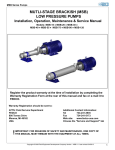
Outline
● These series provide remote space optical transfer units compatible with the Mitsubishi
Electric's PLC `CC-Link Ver. 1.10' (hereinafter, referred to as C remote SOTs).
● The C remote SOT is a remote I/O unit where a single station can be occupied by a
system.
● Up to 64 C remote SOTs can be connected with a single master unit.
● It is a parallel optical transfer unit with 16 input bits and 16 output bits.
● The SOT-CP801 series can communicate with the SOT-3102H3, SOT-NP801, SOT-V801
and SOT-V801R series.
● The SOT-CP803 series can communicate with the SOT-3302H3, SOT-NP803, SOT-V803
series.
The names of systems, product, companies, etc. shown in this manual are trademarks of
relevant companies.
● The models compatible with the CC-Link, Ver. 1.10
are
marked with the logo shown to the right.
The CC-Link Ver.1.10 applies only to the specified optical transfer units.
Make sure your unit has the improvement code "A" ( or another alphabet ) following the
Lot.No. printed on the name plate on the back of the unit.
Lot
OI
A
Improvement code
- 2 -
DS4-2170
Contents
………………………………………………… 4
1. Precautionary Notes
2. Construction
……………………………………………………………… 5
2-1.Model
5
2-2.Example of wiring
5
2-3.Applicable master/local units
5
3. Component Names and Functions
………………………… 6
…………………………………………… 7
4. Settings and Procedure
4-1.Procedure
7
4-2.Switch settings
8
4-3.Description of Modes
10
4-4.Installation
11
………………………………………………… 12
5. Electric Connection
5-1.Connection diagram
12
5-2.Caution in wiring
14
…………………………………………… 15
6. Programming Procedure
6-1.Outline of data exchange
15
6-2.Master station input/output signals
17
6-3.Master station buffer memory
18
6-4.Data processing time
23
6-5.Programming
24
……………………………………………………… 27
7. Trouleshooting
7-1.In case a problem occurs
27
7-2.Troubleshooting
28
8. Maintenance and Inspection
9. Specifications
…………………………………… 32
………………………………………………………… 33
9-1.CC-Link specifications
33
9-2.Optical transfer specifications
33
10. Schematic
……………………………………………………………… 34
11. Gurantees
…………………………………………………………… 35
12. Revision History
…………………………………………………… 35
- 3 -
DS4-2170
1. Precautionary Notes
1-1.Power supply
Use a regulated voltage ( 24 VDC ± 10% ) power supply voltage that meets the specifications
for this unit.
1-2.Resetting time
The unit does not function for about a minute after power-up as the internal resetting circuit
is activated during this period.
1-3.Operation mode selection ( in M/S mode )
The parallel optical transfer unit should be in the master mode when the other one is in the
slave mode or vice versa. The unit has been factory-set to the master mode. To change
the operation mode to slave, turn the mode select switch ( SW1 ) at the top of the main body
on.
1-4.Caution in installation
Use this unit indoor. Do not use it where:
① there may be dust, suspended particles or water or oil splashes that will damp optical
signals,
② an evaporated solvent or corrosive gas exists,
③ a light containing much infrared rays such as sunlight or incandescent light ( disturbing
light ) directly enters the projector/receiver,
④ the unit may be exposed to a temperature, humidity, vibration or impact that exceeds the
rating,
⑤ the SOT's optical passage may be interrupted by a person or another obstacle, or
⑥ a device that will generate a strong magnetic field ( e.g. electromagnetic contactor or
motor ) or a source of radio frequencies ( e.g. inverter ) is used.
1-5.Extention of the cable
The data link and power cables should be separately extended.
① Power cable specifications
0.3 mm 3 or more. The cable should be as short as possible and must not exceed 50 m.
Install a regulated voltage power supply within 50 m. The extension should be adjusted
in consideration of voltage drop.
② Data link cable
Specified by the baud rate, etc. See section 5 `Electric Connection.'
Use a data link cable dedicated for CC-Link.
A shielded power cable is recommended.
1-6.The following instructions should be observed in routing the data link and power cables to
protect them from noises and surges.
① They should be separately wired and must not be laid near or bundled together with the
main circuit or any line with a high voltage or load ( should be at least 100 mm away from
them ) .
② The same applies to cable relays.
1-7.Communication settings
This unit requires several items to be set with switches, including the station No. and baud
rate. See 4-2 `Switch settings.'
1-8.Terminal resistors
A terminal resistor provided with the master/slave unit should be installed at each end of
the data link cable.
- 4 -
DS4-2170
2. Construction
2-1.Model
SOT− CP
8
01
Optical axis direction
H: Head-on
S: Side-on
Transfer distance
01: 1 m
03: 3 m
Number of input/output bits
8: 8 bits each
Series model
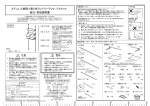
2-2.Example of wiring
Sequencer
CPU
Sequencer
CPU
Master
unit
CC-Link
SOT-CP
801
SOT-CP
CC-Link
801
Terminal resistor
SOT-CP
801
801
SOT-CP
801
801
SOT-NP
MINI-S3 Link
Terminal resistor
Terminal resistor
SOT-NP
Parallel I/O
2-3.Applicable master/local units
The C remote SOT can be connected with the following master/local units.
・ A1SJ61BT11:
Master/local unit for AnS/A2US series
・ AJ61BT11:
Master/local unit for A series
・ A1SJ61QBT11: Master/local unit for Q2AS series
・ AJ61QBT11:
Master/local unit for QnA series
・ QJ61BT11:
Master/local unit for Q series
- 5 -
I/O
DS4-2170
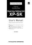
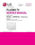
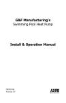
3. Component Names and Functions
④
⑤ ⑥ ⑧⑦
⑬
⑨
⑫
8
7
6
4
5
E RR
型 式
③
RUN
3
C TL
TCD
3
S D
2
D T
R D
1
P OW
RCV
①
⑮
8
7
6
5
4
1
OU T
⑪
(SIDE
サイドON)
オン)
⑪(
2
I N
②
⑫
(HEAD
ON)
(
ヘッドオ
ン)
⑭
⑩
① Station No. select switches ( x2 )
Used to select the remote station No. of the unit between 1 and 64.
② Baud rate select switch
Used to select the baud rate of the CC-Link between 0 and 4.
③ Mode select switches
Used to select the M/S mode, X mode, etc.
④ POW ( power lamp )
Lights ( red ) when the main body is normally supplied with power.
⑤ DT/RCV ( normal data lamp/stabilized reception lamp )
DT lights ( red ) when data transfer between the other SOT is possible. RCV lights
( green ) when the reception level of your SOT is stabilized.
⑥ CTL/TCD ( transfer stop input lamp/transmission stop input lamp )
CTL lights ( red ) when the optical transfer stops. TCD lights ( green ) when the optical
transmission stops.
⑦ RUN/ERR ( data link execution lamp/communication error lamp )
RUN lights ( green ) when data is normally exchanged with the master station. ERR lights
( red ) when a CC-Link communication error occurs and blinks when the position ( s ) of the
① station No. select switches or ② baud rate select switch is ( are ) changed with the
power supply on.
⑧ SD/RD ( data transmission lamp/data reception lamp )
SD lights ( green ) when data is being transmitted through the CC-Link. RD lights ( red )
when data is being received through the CC-Link.
⑨ IN ( data input lamps )
Indicate bit by bit the status of the data transferred to the other transfer unit ( RY ) .
⑩ OUT ( data output lamps )
Indicate bit by bit the status of the data transferred from the other transfer unit ( RX ) .
⑪ Projector/receiver
Units are offered in two types: head-on and side-on.
The head-on type has projector/receiver elements on the head.
The side-on type has projector/recei ver elements beside the nameplate.
⑫ Light intensity control knob
Used to adjust the light intensity and, consequently, transfer distance when you do not
want to send the light beyond the specified transmission distance.
Remove the cover and adjust the knob. ( The cover is fixed with screws. )
⑬ Mounting holes
Holes used to fix the main body ( 2 holes, 5 mm dia. ) .
⑭ Power connector ( MSTB 2.5/2-ST-5.08, Phoenix Contact )
A connector terminal block for connecting the power supply.
⑮ Signal connector ( MSTB 2.5/5-ST-5.08, Phoenix Contact )
A connector terminal block for transferring signals through the CC-Link.
- 6 -
DS4-2170
4. Settings and Procedure
4-1.Procedure
Start
↓
Set switches
Select the station No., baud rate and
See 4-2 `Switch Settings.'
operation mode of the C remote SOT.
↓
Installation
See 4-4 `Installation.'
Install the SOT on the platform.
↓
Connection of cables
See 5-1 `Connection
Diagram'
Connect the power and data link cables.
5-2 `Caution in Wiring.'
↓
Relocation of optical axis
Relocate the optical axis and check the RCV
lamp on each SOT.
↓
Setting of master unit
Set each part of the master unit.
↓
Circuit check
Check the CC-Link circuit
↓
Preparation of transmission/reception program
Prepare a sequence program for
See 6 `Programming Procedure.'
transmitting/receiving data to and from the C
remote SOT.
↓
Transmission/reception status check
Check the transmission/reception status from
the C remote SOT input/output status and
errors detected by the master unit.
↓
End
For the steps enclosed by dot lines, see the User's Manual for Master/Local Unit.
- 7 -
DS4-2170
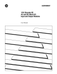
4-2.Switch settings
Mode select switches
Station No. select
switches
Baud rate select switch
4-2-1.Setting the station No. select switches
① Station No. select switches
Description
X10 switch: Used to specify the first digit
of the station No.
X1 switch:
Used to specify the second digit
of the station No.
Select a station No. between 01 and 64.
② The station No. should be `01' when there is no previous station or `previous station
No. + number of stations occupied by the unit to which the previous station belongs.'
( If the station No. of the previous station is `01' and the unit occupies two stations,
for example, the station No. of your station should be `03.' )
③ The switches have been factory-set to `00.'
④ Take care not to skip or duplicate any station No.
⑤ Precautionary instructions to be followed in making a connection with the CC-link are
shown in the User's Manual for CC-Link Master/Local Unit.
4-2-2.Setting the baud rate select switch
① Baud rate select switch
No.
Description
0
156 kbps
1
625 kbps
2
2.5 Mbps
3
5 Mbps
4
10 Mbps
5-9
Setting error ( cannot be used )
② This setting must be consistent with that of the master station.
If not, communication with the master station is impossible.
③ The switch has been factory-set to `0.'
④ Precautionary instructions to be followed in making a connection with the CC-link are
shown in the User's Manual for CC-Link Master/Local Unit
- 8 -
DS4-2170
4-2-3.Mode select switch
① Description
Description
Raise the lever to turn on.
SW1: M/S (master or slave)
SW5: Normally off
SW2: Mode (M/S or X)
SW6: Normally off
SW3: Normally off
SW7: Normally off
SW4: TRE
SW8: Normally off
② M/S select switch ( SW1 )
SW1
OFF
Master ( transmission preceded )
ON
Slave ( reception preceded )
When data is communicated bi-directionally between two transfer units, the one should
be designated as master and the other as slave.
The switch has been factory-set to `master.'
③ Mode select switch ( SW2 )
SW2
OFF
M/S mode
ON
X mode
M/S mode: Standard bi-directional communication
X mode: Bi-directional/uni-directional communication
Description of each mode is given in 4-3 `Description of Operation Modes.'
The switch has been factory-set to `M/S mode.'
④ TRE switch ( SW4 )
SW4
OFF
Output cleared in case of
count-up
ON
Output retained in case of
count-up
Count-up: Elapse of a given time after the completion of refresh data reception through
the CC-Link and before the completion of next refresh data reception.
This time is determined by the baud rate ( fixed ) .
Count-up time by the baud rate
Baud rate
Count-up time ( ms )
10M
104.8
5M
104.8
2.5M
209.7
625K
833.8
156K
1677.6
The switch has been factory-set to `retain the output in case of count-up.'
4-2-4.After setting the switches
Attach the nameplate provided to prevent changes to the switch settings.
( The rear of the nameplate is adhesive.
attach. )
- 9 -
Remove a plastic sheet from the rear and
DS4-2170
4-3.Description of Modes
4-3-1.M/S mode
Set the mode select switch ( SW2 ) to OFF to select the M/S mode.
① Designate your unit as master or slave.
When data is communicated bi-directionally between two transfer units, the one should
be designated as master and the other as slave. Set the M/S select switch ( SW1 ) to
ON to designate your unit as slave.
② Turn the power supply on. The power lamp ( POW ) lights.
③ When the other transfer unit is out of the operational range ( not synchronized ) , the
master repeats transmission and reception at regular intervals. The slave waits a
signal transmitted from the master.
④ When the other transfer unit is within the operational range ( synchronized ) :
a. A signal is transmitted from the master to the slave.
b. The slave detects the end of the signal transmitted from the master and transmits
a signal in response to it.
c. After transmitting a signal, the master receives the signal transmitted from the
slave, detects the end of that signal, and transmits another signal. The master
and slave detect the end of each signal transmitted from the other and alternately
repeats the transmission and reception.
⑤ When the units are synchronized, the normal data lamp ( DT ) lights.
If the received data is determined normal, the relevant data output turns on.
⑥ If the reception level drops below 120% of the on-level of the DT output due to a stain
on the projector/receiver or an optical axis shift, the stabilized reception lamp ( RCV )
and the RCV output turn off.
⑦ With the transfer stop input ( CTL ) on, the transfer stop lamp ( CTL ) lights and, as the
transmission and reception are forcedly prohibited, the DT/RCV lamp and all data
outputs turn off.
⑧ With the select the M/S mode, the remove input `RY1F' on the C remote SOT is used
for transfer stop input ( CTL ) .
4-3-2.X mode
① Select the X mode
Set the mode select switch ( SW2 ) to ON to select the M/S mode.
In the X mode, the M/S select switch is ineffective.
② Turn the power supply on. The power lamp ( POW ) lights.
③ Select the transmission stop function.
When data is communicated uni-directionally between two transfer units, the
transmission stop input ( TCD ) should be used. With the TCD input on, the
transmission stops and only the reception remains possible.
④ When the other transfer unit is out of the operational range ( not synchronized ) , the
transfer unit with the TCD input off repeats transmission and reception at regular
intervals. The one with the TCD input on waits a signal transmitted from the other.
⑤ When the other transfer unit is within the operational range ( synchronized ) :
a. The transfer unit with the TCD input off repeats transmission and reception at
regular intervals.
b. If the one with the TCD input on normally receives an optical signal from the other,
it turns the DT and relevant data output on.
c. If the TCD input turns off at this time, data can be bi-directionally communicated
as in the M/S mode. ]
⑥ With the select the X mode, the remove input `RY1F' on the C remote SOT is used for
transmission stop input ( TCD ) .
- 10 -
DS4-2170
4-4.Installation
4-4-1.Drilling mounting holes
M4 screws are recommended for mounting.
Optical axis
direction
A threaded hole that
accommodates an M4
※ Note 1: Tighten the C remote SOT mounting screws to a torque not higher than 8 kgf-cm.
4-4-2. Place for installation
Install the unit indoor.
To prevent malfunction and disorder, do not use it where:
① there may be dust, suspended particles or water or oil splashes that will damp optical
signals,
② an evaporated solvent or corrosive gas exists,
Note: The main body is made of a resin and must not be cleaned with paint thinner or
another solvent.
③ a light containing much infrared rays such as sunlight or incandescent light ( disturbing
light ) directly enters the projector/receiver,
④ the unit may be exposed to a temperature, humidity, vibration or impact that exceeds
the rating,
⑤ the SOT's optical passage may be interrupted by a person or another obstacle,
⑥ a reflecting surface may draw near the front of the receiver ( to cause optional
intereference ) , or
⑦ a device that will generate a strong magnetic field ( e.g. electromagnetic contactor or
motor ) or a source of radio frequencies ( e.g. inverter ) is used.
- 11 -
DS4-2170
5. Electric Connection
5-1.Connection diagram
5-1-1.Connection of the C remote SOT
Connector terminal
block arrangement
Blue White Yellow Braide
For 24 VDC power supply
From previous station
For next station
CC-Link dedicated cable
CC-Link dedicated cable
Each cable should be stripped to 7 mm.
5-1-2.Mutual connection of link data cables ( for CC-Link, Ver. 1.10 )
The station-to-station distance and total extension distance are determined by the baud
rate setting and the construction of units used.
① Maximum transfer distance
Baud rate
156kbps
625kbps
20 cm or more
Station-to-station
cable length
Maximum transfer
distance
1200m
2.5Mbps
5Mbps
10Mbps
400m
160m
100m
900m
Maximum transfer distance
R
R
M
R
R
R
M : Master station
Terminal resistor
Terminal resistor
R : Remote station
② For T branch connection
Baud rate
Stationtostation
cable
length
156kbps
625kbps
1 m or more
Between master/local
station or intelligent
device station and
previous/subsequent
station
※1
Between remote I/O
station and remote
device station
※2
2 m or more
30cm or more
Maximum number of units
connected per branch
※3
Maximum trunk length
T branch interval
Maximum branch length
Total branch length
Terminal resistor
T branch terminal
block/connector
2.5M/5M/10Mbps unacceptable
For the system only consisting of remote I/O and
remote device stations
For the system including local and intelligent
device stations
6
500m
※4
100m
Excluding cables between terminal resistors and
branches
Not limited
8m
200m
50m
110 Ω 1/2W × 2
Terminal block:
A commercial one
Connector:
FA sensor connector
Cable length per branch
Total length of branches
Connected between DA and DB at trunk ends
Trunk cables should be stripped to a shorter
length.
※3
※4
R
※2
R
※1
M
R
※1
※2
R
※2
R
※1
Terminal resistor
L
Terminal resistor
※1 ※1
R
M : Master
station
※2
L
L : Local
※1
R
※1
L
※2
R
or intelligent device station
R
R : Remote
I/O or device station
Note: All units and cables on the system should be compatible with the CC-Link, Ver. 1.10.
- 12 -
DS4-2170
5-1-3.Mutual connection of link data cables ( when units older than the CC-Link, Ver. 1.10 are
used )
The station-to-station distance and total extension distance are determined by the baud
rate setting and the construction of units used.
( The following table applies when FAN-SB and FANC-SBH are used. )
① For the system only consisting of remote I/O and remote device stations
Baud rate
Total number
Cable length at each
Minimum cable length
of remote
end of master station
between remote
*2
stations *3
stations
156 Kbps
625 Kbps
2.5 Mbps
5 Mbps
*1
64 or less
1.0 m or more
Total cable extension *4
FANC-SB
0.3 m or more
0.6
0.3
0.4
0.6
0.7
1.0
0.3
0.4
0.3
10 Mbps
48 or less
32 or less
m
m
m
m
m
m
m
m
m
or
or
or
or
or
or
or
or
or
1200
600
200
110
150
50
more
more
more
more
more
more
more
more
more
m
m
m
m
m
m
or
or
or
or
or
or
FANC-SBH
less
less
less
less
less
less
1200
900
400
160
m
m
m
m
or
or
or
or
less
less
less
less
20 m or less
30 m or less
80 m or less
100 m or less
100 m or less
50 m or less
80 m or less
100 m or less
*1
M
R
*2
R
*3
*3
R
R
R
*3
M : Master station
Terminal resistor
R : Remote station
Terminal resistor
*4
② For the system including local and intelligent device stations
Baud rate
156 Kbps
625 Kbps
2.5 Mbps
5 Mbps
Cable length at each end of
Minimum cable length
master, local and intelligent
between remote I/O and
device stations
remote device stations
*1
2.0 m or more
0.6
0.3
0.6
0.7
1.0
10 Mbps
M
0.3 m or more
R
*1
*2
R
m
m
m
m
m
R
or
or
or
or
or
*2
FANC-SB
m
m
m
m
m
m
m
or
or
or
or
or
or
or
less
less
less
less
less
less
less
1200
600
200
110
150
L
*1
L
*1
m
m
m
m
m
or
or
or
or
or
less
less
less
less
less
50 m or less
80 m or less
100 m or less
*1
*3
FANC-SBH
*2
1200
600
200
110
150
50
80
more
more
more
more
more
R
Total cable extension
R
Terminal resistor
Terminal resistor
*3
M : Master
station
L : Local
or intelligent device station
R : Remote
I/O or device station
Install the terminal resistor provided with the master/local unit at each end of the data
link cable.
The terminal resistor type depends on the cable.
Install 110 Ω for FANC-SB or FANC-SBZ or 130 Ω for FANC-SBH.
Note: All units and cables on the system should be compatible with the CC-Link, Ver. 1.10.
For detail, see the User's Manual for CC-Link System Master/Local Unit.
- 13 -
DS4-2170
5-1-4.Maximum number of units connected
The C remote SOT is a remote I/O station and occupies a single station.
Up to 64
SOTs maybe connected.
When other units are to be connected, the following conditions should be met.
①{(1×a)+(2×b)+(3×c)+(4×d)}≦64
a: Number of units that occupy a single station each
b: Number of units that occupy two stations each
c: Number of units that occupy three stations each
d: Number of units that occupy four stations each
②{(16×A)+(54×B)+(88×C)}≦2304
A: Number of remote I/O stations
B: Number of remote device stations
C: Number of local, standby master and intelligent device stations
5-2.Caution in wiring
( 1 ) The data link cable should be connected with a CC-Link dedicated cable.
Use the same type of data link cables for the same link. Do not use various types of
data link cables for the same link.
( 2 ) The shielded ( braided ) cable to be connected to the connector terminal block should be
stripped to as small a length as possible.
( 3 ) Install the terminal resistor provided with the master/local unit at each end of the data
link cable.
( 4 ) Using a noise filter, EMI filter and/or ferrite core with the power cable may be effective
to suppress the noise at the power supply.
( 5 ) Power cable extension
The power cable extension should be as short as possible and must not exceed 50 m.
Use a cable with 0.3 mm 2 or thicker conductor.
( Install a regulated voltage power supply within 50 m. The extension should be
adjusted in consideration ofvoltage drop. A shielded power cable is recommended.
( 6 ) The following instructions should be observed in routing the data link cables to protect
them from noises and surges.
① The data link and power cables must not be laid near or bundled together with the
main circuit or any line with a high voltage or load ( should be at least 100 mm away
from them ) .
② The data link and power cables to the C remote SOT should also be separated.
( 7 ) No conductor should protrude from the cables connected to the connector terminal block.
Braided wires should be insulated using tubes or such to prevent the contact with other
wires.
( 8 ) Cables should be secured so that conductors will not be cut due to vibration.
( 9 ) The braid ( shielding ) of the data link cable should be grounded at both ends of the
cable in accordance with Class D ( Class 3 ) regulations.
( 10 ) All units and cables on the system should be compatible with the CC-Link, Ver. 1.10.
- 14 -
DS4-2170
6. Programming Procedure
6-1.Outline of data exchange
6-1-1Data exchange flow
The data exchange flow between the C remote SOT and the master station is outlined
belo 、 m w.
Sequencer CPU
Master station
Remote I/O station
①
[ SET Yn0 ]
C remote SOT
Refresh command
②
[ SET Yn6 ]
Data link start
Buffer memory
④
[
FROM ]
③
Remote input
( RX )
⑤
[
TO
]
Link scan
Optical data inputs
( OUT1-OUT 8 )
⑥
Remote output
( RY )
Link scan
Optical data outputs
( IN 1-IN 8 )
① The refresh command ( Yn0 ) turns on.
② The request for data link start ( Yn6 or Yn8 ) turns on.
③ The link is scanned to store the optical data inputs ( OUT ) from the C remote SOT in
the remote input ( RX ) area of the master station.
④ Data is uploaded from the remote input ( RX ) area of the master station according to
the FROM command.
⑤ Data is downloaded from the remote output ( RY ) area of the master station according
to the TO command.
⑥ The link is scanned to send data in the remote output ( RY ) area of the master station
to the optical data outputs ( IN ) of the C remote SOT.
- 15 -
DS4-2170
6-1-2.Processing of remote input/output signals of the C remote SOT
Remote input/output signals of the C remote SOT are processed via the remote input
( RX ) and remote output ( RY ) areas of the master station.
Remote inputs/outputs of the master station are assigned to addresses E0H to 15FH
( RX ) and 160H to 1DFH ( RY ) in the buffer memory.
For detail of the buffer memory, see 6-3 `Buffer memory of master station.'
① Remote input ( RX ) area
Optical data inputs of the C remote SOT are always stored in the remote input area of
the master station through link scanning.
Master station
Address
Station No.1
Station No.2
Station No.3
Station No.4
Remote input ( RX )
C remote SOT
Link scan
Optical data inputs ( OUT )
E0H
RX0F -RX00
OUT1 - OUT8
E1H
RX1F -RX10
RCV
E2H
RX2F - RX20
OUT1 - OUT8
E3H
RX3F - RX30
RCV
E4H
RX4F - RX40
OUT1 - OUT8
E5H
RX5F - RX50
RCV
E6H
RX6F - RX60
OUT1 - OUT8
E7H
RX7F - RX70
RCV
E8H
RX8F - RX80
Station No.1
Station No.2
Station No.3
Station No.4
…
② Remote output (RY) area
Data in the remote output area of the master station is always sent to optical data
outputs of the C remote SOT through link scanning.
Master station
Address
For
s tation No.1
C remote SOT
Remote output ( RY )
Optical data outputs ( IN )
160H
RY0F - RY00
161H
RY1F - RY10
CTL/TCD
Link scan
IN1 -IN8
For
s tation No.2
162H
RY2F - RY20
IN1 -IN8
163H
RY3F - RY30
CTL/TCD
For
s tation No.3
164H
RY4F - RY40
IN1 -IN8
165H
RY5F - RY50
CTL/TCD
166H
RY6F - RY60
IN1 -IN8
167H
RY7F - RY70
CTL/TCD
168H
RY8F - RY80
For
s tation No.4
…
- 16 -
Station No.1
Station No.2
Station No.3
Station No.4
DS4-2170
6-2.Master station input/output signals
The master station input/output signals to and from the CPU unit are listed below.
For detail of the input/output signals, see the User's Manual for CC-Link System
Master/Local Unit.
`n' in the device No. column represents the starting I/O No. of the master station, which is
determined by the number of units installed in front of the master station.
If the starting I/O No. of the master station is X/Y20, for example:
X ( n + 0 ) -X ( n + 1F )= X20-X3F
Y ( n + 0 ) -Y ( n + 1F )= Y20-Y3F
I/O Signal List
Device No.
Signal name
Device No.
Signal name
Xn0
Unit failure
Yn0
Xn1
Your station data-linked
Yn1
Xn2
Parameters set
Yn2
Xn3
Other station data-linked
Yn3
Xn4
Request for unit reset accepted
Yn4
Request for unit reset
Xn5
(Not used)
Yn5
(Not used)
Xn6
Data linking per buffer memory
parameters normally started
Yn6
Request for data linking per buffer
memory parameters
Xn7
Data linking per buffer memory
parameters abnormally started
Yn7
(Not used)
Xn8
Data linking per E2PROM parameters
normally started
Yn8
Request for data linking per E2PROM
parameters
Xn9
Data linking per E2PROM parameters
abnormally started
Yn9
(Not used)
XnA
Parameters normally registered in
E2PROM
YnA
Request for registration of parameters in
E2PROM
XnB
Parameters abnormally registered in
E2PROM
YnB
XnC
XnD
XnE
XnF
X(n+1)0
X(n+1)1
X(n+1)2
X(n+1)3
X(n+1)4
X(n+1)5
X(n+1)6
X(n+1)7
X(n+1)8
X(n+1)9
X(n+1)A
X(n+1)B
X(n+1)C
X(n+1)D
X(n+1)E
X(n+1)F
(Not used)
Unit ready
(Not used)
YnC
YnD
YnE
Y(n+F)
Y(n+1)0
Y(n+1)1
Y(n+1)2
Y(n+1)3
Y(n+1)4
Y(n+1)5
Y(n+1)6
Y(n+1)7
Y(n+1)8
Y(n+1)9
Y(n+1)A
Y(n+1)B
Y(n+1)C
Y(n+1)D
Y(n+1)E
Y(n+1)F
- 17 -
Refresh command
(Not used)
(Not used)
DS4-2170
6-3.Master station buffer memory
6-3-1.Master station buffer memory
The master station buffer memory is used for data exchange between a remote unit and
the CPU unit.
Assignment of buffer memory addresses is shown below.
For detail of the buffer memory, see the User's Manual for CC-Link System Master/Local
Unit.
Master Station Buffer Memory Addresses
Address
Item
Description
Read/write
※3
(hexadecimal)
0H - 5FH
Parameter
information area
Stores the information (parameters)
required for data linking.
Read/
write enabled
※1
60H - DFH
(Not used)
E0H -15FH
Remote input
(RX)
Stores the status of inputs from
remote/local stations.
Read only
160H -1DFH
Remote output
(RY)
Sto res the status of outputs to remote/local
stations.
Write only
1E0H -2DFH
Remote register
(RWw)
Stores the data transmitted to remote/local
stations.
Write only
2E0H -3DFH
Remote register
(RWr)
Stores the data received from remote/local
stations.
Read only
3E0H -5DFH
(Not used)
5E0H -5FFH
Link relay(SB)
Stores the data link status.
600H -7FFH
Link register(SW)
Stores the data link status.
Read/
write enabled
※2
800H -9FFH
(Not used)
A00H -FFFH
Random access
buffer
Used for dedicated instructions such as
RIRD and RIWT.
Read/
write enabled
※1
※1
※ 1: Do not write any data in the areas not used.
Doing so may lead to an error.
※ 2: Writing is not enabled for some devices.
※ 3: Do not write in the read-only areas from the sequencer CPU.
- 18 -
DS4-2170
6-3-2.Setting the parameter information area
Specify the conditions for data linking in the parameter information area of the master
station.
① Number of stations connected (address 01H, defaulted 64)
Specify the number of remote/local stations connected with the master station
(including reserved ones).
Specify a number between 1 and 64.
This is not the number of occupied stations.
② Maximum number of retries (address 02H, defaulted 3)
Specify the maximum number of retries to be made for a remote or local station in
case of data linking error.
Specify a number between between 1 and 7.
If data linking is not normally performed after the specified number of retries, the
remote or local station is considered as `data link failed station.'
③ Number of automatically reset stations (address 03H, defaulted 1)
Specify the number of remote/local stations that can be reset during a single link scan.
Specify a number between 1 and 10.
④ Operation status in case of CPU breakdown (address 06H, defaulted 0)
Choose to cease the data linking (set to 0) or continue (set to 1) when the CPU unit of
the master station `stops due to an error.'
⑤ Reserved stations (addresses 10H to 13H, defaulted 0)
Any of the remote/local stations specified as connected but not actually connected
may be considered as data link failed.
To prevent this, set the relevant bit(s) to 0.
If any of the remote/local stations actually connected is specified as reserved, it will
never be data-linked.
Set on the bits corresponding to the station Nos. of reserved stations.
For the unit occupying two or more remote/local stations, set on the bit corresponding
to the station No. specified by the station No. select switches.
1 to 64 in the following table represent station Nos.
Address b15 b14 b13 b12 b11 b10
b9
b8
b7
b6
b5
b4
b3
b2
b1
b0
10H
16
15
14
13
12
11
10
9
8
7
6
5
4
3
2
1
11H
32
31
30
29
28
27
26
25
24
23
22
21
20
19
18
17
12H
48
47
46
45
44
43
42
41
40
39
38
37
36
35
34
33
13H
64
63
62
61
60
59
58
57
56
55
54
53
52
51
50
49
- 19 -
DS4-2170
⑥ Error invalid station ( addresses 14H to 17H, defaulted 0 )
Local/remote stations specified as error invalid are not considered as 'data link failed'
by the master and remote stations if they cannot be data-linked due to power failure
or for another reason.
Note that no error can be detected at error invalid stations.
If they are also specified as reserved, they are considered as not connected.
Set on the bits corresponding to the station Nos. of the stations to be error-invalid.
For the unit occupying two or more remote/local stations, set on the bit corresponding
to the station No. specified by the station No. select switches.
1 to 64 in the following table represent station Nos.
Address b15 b14 b13 b12 b11 b10
b9
b8
b7
b6
b5
b4
b3
b2
b1
b0
14H
16
15
14
13
12
11
10
9
8
7
6
5
4
3
2
1
15H
32
31
30
29
28
27
26
25
24
23
22
21
20
19
18
17
16H
48
47
46
45
44
43
42
41
40
39
38
37
36
35
34
33
17H
64
63
62
61
60
59
58
57
56
55
54
53
52
51
50
49
⑦ Station information ( addresses 20H to 5FH )
Specify the type of each of the remote/local stations connected or specified as
reserved.
Data structure
b15
-
b12 b11
Station type
-
b8 b7
-
0: C remote SOT
b0
Station
Number of
occupied stations
1∼64
1: Single station
occupied
( 01H-40H )
( remote I/O station )
Buffer memory addresses are assigned to units as shown below.
Unit
Address
Unit
17 th
Address
30H
Unit
1 st
20H
33 rd
2 nd
21H
18 th
31H
34 th
3 rd
22H
19 th
32H
35 th
4 th
23H
20 th
33H
36 th
5 th
24H
21 st
34H
37 th
6 th
25H
22 nd
35H
7 th
26H
23 rd
36H
8 th
27H
24 th
9 th
28H
25 th
10 th
29H
26 th
39H
42 nd
11 th
2AH
27 th
3AH
43 rd
Address
40H
Unit
Address
49 th
50H
41H
50 th
51H
42H
51 st
52H
43H
52 nd
53H
44H
53 rd
54H
38 th
45H
54 th
55H
39 th
46H
55 th
56H
37H
40 th
47H
56 th
57H
38H
41 st
48H
57 th
58H
49H
58 th
59H
4AH
59 th
5AH
12 th
2BH
28 th
3BH
44 th
4BH
60 th
5BH
13 th
2CH
29 th
3CH
45 th
4CH
61 st
5CH
14 th
2DH
30 th
3DH
46 th
4DH
62 nd
5DH
15 th
2EH
31 st
3EH
47 th
4EH
63 rd
5EH
16 th
2FH
32 nd
3FH
48 th
4FH
64 th
5FH
- 20 -
DS4-2170
6-3-3.Inputs/outputs of C remote SOT
Optical data inputs of the C remote SOT are always stored in the remote input ( RX )
area in the buffer memory of the master station through link scanning.
Data in the remote output ( RY ) area in the buffer memory of the master station is
always sent to optical data outputs of the C remote SOT through link scanning.
Remote Inputs/Outputs
Signal direction:
C remote SOT → Master unit
Device No.
RX00
Signal direction:
Master unit → C remote SOT
Description
Device No.
Optical data inputs OUT 1 RY00-RX0F
Description
Reserve
RX01
〃
OUT 2
RY10
RX02
〃
OUT 3
RY11
〃
IN 2
RX03
〃
OUT 4
RY12
〃
IN 3
RX04
〃
OUT 5
RY13
〃
IN 4
RX05
〃
OUT 6
RY14
〃
IN 5
RX06
〃
OUT 7
RY15
〃
IN 6
RX07
〃
OUT 8
RY16
〃
IN 7
〃
IN 8
Optical data outputs
RX08-RX0E
Not used
RY17
RX0F
RCV
RY18-RX1E
Not used
RX10-RX1F
Reserve
RY1F
CTL/TCD
IN 1
① OUT1 to 8 ( RX00 to RX07 )
Outputs the data sent from the normal SOT.
② RVC ( RX0F )
Set to '1' during stabilized reception.
③ IN1 to 8 ( RY10 to RY17 )
Inputs the data to be transmitted to the normal SOT.
④ CTL/TCD ( RY1F )
The transmission and reception are ceased with SW2 off and RY1F on ( CTL ) .
The transmission is ceased with SW2 on and RY1F on ( TCD ) .
- 21 -
DS4-2170
6-3-4.Remote input ( RX ) area
Remote inputs of the C remote SOT are stored in the remote input area in the buffer
memory of the master station at the relevant addresses.
The correspondence between the station No. of the C remote SOT and the applicable
buffer memory address is shown below.
Master Station Buffer Memory Addresses ( C Remote SOT → Master Station ( RX ))
Station
No.
Buffer
memory
Station
No.
address
Buffer
memory
Station
No.
address
1
E0H-E1H
14
2
E2H-E3H
3
E4H-E5H
4
E6H-E7H
5
E8H-E9H
6
7
Buffer
memory
Station
No.
address
FAH-FBH
27
15
FCH-FDH
16
FEH-FFH
17
100H-101H
18
102H-103H
EA0-EBH
19
ECH-EDH
20
8
EEH-EFH
9
F0H-F1H
10
Buffer
memory
Station
No.
Buffer
memory
12EH-12FH
53
148H-149H
address
address
114H-115H
40
28
116H-117H
41
130H-131H
54
14AH-14BH
29
118H-119H
42
132H-133H
55
14CH-14DH
30
11AH-11BH
43
134H-135H
56
14EH-14FH
31
11CH-11DH
44
136H-137H
57
150H-151H
104H-105H
32
11EH-11FH
45
138H-139H
58
152H-153H
106H-107H
33
120H-121H
46
13AH-13BH
59
154H-155H
21
108H-109H
34
122H-123H
47
13CH-13DH
60
156H-157H
22
10AH-10BH
35
124H-125H
48
13EH-13FH
61
158H-159H
F2H-F3H
23
10CH-10DH
36
126H-127H
49
140H-141H
62
15AH-15BH
11
F4H-F5H
24
10EH-10FH
37
128H-129H
50
142H-143H
63
15CH-15DH
12
F6H-F7H
25
110H-111H
38
12AH-12BH
51
144H-145H
64
15EH-15FH
13
F8H-F9H
26
112H-113H
39
12CH-12DH
52
146H-147H
−
−
6-3-5.Remote output ( RY ) area
Remote outputs to the C remote SOT are stored in the remote output area in the buffer
memory of the master station at the relevant addresses.
The correspondence between the station No. of the C remote SOT and the applicable
buffer memory address is shown below.
Master Station Buffer Memory Addresses ( Master Station ( RY ) → C Remote SOT )
Station
No.
Buffer
memory
Station
No.
address
Buffer
memory
Station
No.
address
Buffer
memory
Station
No.
address
Buffer
memory
Station
No.
address
Buffer
memory
address
1
160H-161H
14
17AH-17BH
27
194H-195H
40
1AEH-1AFH
53
1C8H-1C9H
2
162H-163H
15
17CH-17DH
28
196H-197H
41
1B0H-1B1H
54
1CAH-1CBH
3
164H-165H
16
17EH-17FH
29
198H-199H
42
1B2H-1B3H
55
1CCH-1CDH
4
166H-167H
17
180H-181H
30
19AH-19BH
43
1B4H-1B5H
56
1CEH-1CFH
5
168H-169H
18
182H-183H
31
19CH-19DH
44
1B6H-1B7H
57
1D0H-1D1H
6
16A0-16BH
19
184H-185H
32
19EH-19FH
45
1B8H-1B9H
58
1D2H-1D3H
7
16CH-16DH
20
186H-187H
33
1A0H-1A1H
46
1BAH-1BBH
59
1D4H-1D5H
8
16EH-16FH
21
188H-189H
34
1A2H-1A3H
47
1BCH-1BDH 6 0
1D6H-1D7H
9
160H-171H
22
18AH-18BH
35
1A4H-1A5H
48
1BEH-1BFH
61
1D8H-1D9H
10
172H-173H
23
18CH-18DH
36
1A6H-1A7H
49
1C0H-1C1H
62
1DAH-1DBH
11
174H-175H
24
18EH-18FH
37
1A8H-1A9H
50
1C2H-1C3H
63
1DCH-1DDH
51
1C4H1C5H
64
1DEH-1DFH
1C6H-1C7H
−
−
12
176H-177H
25
190H-191H
38
1AAH-1ABH
13
178H-179H
26
192H-193H
39
1ACH-1ADH 5 2
- 22 -
DS4-2170
6-4.Data processing time
The data processing time by the C remote SOT is calculated as follows.
6-4-1.Time required for transmitting data
Maximum processing time =
MS + LS x 2 + optical transfer time x 2
6-4-2.Time required for uploading received data
Maximum processing time = MS x 2 + LS x 2
MS: Scan time by sequence program of master station
LS: Link scan time
Optical transfer time: Time required for optical transfer from C remote SOT to
normal SOT
M/S mode
: 15ms MAX
X mode
: 20ms MAX
The link scan time for the CC-Link is calculated as follows.
LS = BT{29.4 + (NI×4.8) + (NW×9.6) + (N×32.4) + (ni×4.8) + (nw×9.6)} + ST
*2
+ {number of communication failed stations x 48 x BT x number of retries}
*2 : This term is required when one or more communication failed stations exist.
BT: A constant ( baud rate )
NI: The largest station No. of a, b and c
( including all occupied stations )
NW: The latest station No. of b and c
A multiple of 8
( including all occupied stations )
N: Number of connected stations
ni: a + b + c
nw: b + c
ST: A constant ( the largest of ① , ② and ③ )
① 800 + (a×15)
② 900 + (b×50)
③ If c ≦ 26, 1200 + ( c x 100 )
If c > 26, 3700 + {( c - 26 ) x 25 }
a: The total number of occupied remote I/O stations
b: The total number of occupied remote device stations
c: The total number of occupied intelligent device stations ( including local ones )
- 23 -
DS4-2170
6-5.Programming
Prepare a PC program using the following example.
This section gives a description assuming the ACPU, AJ61bT11 and C remote SOT
set as follows for your reference.
Example of system construction
① AJ61BT11 is installed in 0 slot.
0 slot
Power supply unit
② Station No. of C remote SOT is 1.
③ Only a single C remote SOT is
connected.
④ Transmitted data is stored at
AJ61
BT11
ACPU
B0010 to B001F and received
data at B0000 to B000F.
・ Station No.01
( 1 ) Parameters setting program
An example program for setting parameters is shown below.
① Data linking per buffer memory parameters ( in debugging )
M9038
[SET
Y0000]
Refresh command
[PLS
M302]
Parameter information is written in buffer memory
X0000 X000F
M302
K
[MOV
with no unit failure and with Unit Ready on.
1
D0
]
A single station connected
D1
]
5 retries
D2
]
A single station automatically reset
K
[MOV
5
K
[MOV
[TO
H
H
0000
0001
1
K
D0
3
]
D3
]
K
[MOV
[TO
H
H
0000
0006
0
(stop)
K
D3
Operation status in case of CPU breakdown
1
]
D4
]
H
[MOV
[TO
H
H
0000
0020
0101
K
D4
1
- 24 -
Remote station information
Station No. 1, 1 station occupied
]
Remote I/O station
DS4-2170
M302
[SET
M303 ]
Request for start of data linking per buffer memory
[SET
Y0006]
Ready on.
[RST
Y0006]
M303
parameters turns on with no unit failure and with Unit
X0006
Request for start of data linking turns off when data
linking is normally started.
[RST
X0007
[FROM
H
0000
H
0668
D10
M303 ]
K
1
]
[RST
Y0006]
[RST
M303 ]
Parameter information of your station is called out
and request for start of data linking turns off when
② Registration of parameters in E 2 PROM
X0020 X0000 X000F
[PLS
M304
[SET
M305
[SET
X000A
[RST
M304 ]
data linking is abnormally started.
Parameters are registered in E2PROM per
registration command (Y20).
M305 ]
Request for registration of parameters turns on with
Y000A]
no unit failure and with Unit Ready on.
Y000A]
Request for registration of parameters turns off when
parameters are normally registered in E2PROM.
[RST
X000B
[FROM
H
0000
H
0668
D10
M305 ]
K
1
]
Parameter information of your station is called out
and request for registration of parameters turns off
[RST
Y000A]
[RST
M305 ]
when parameters are abnormally registered in E2PROM.
③ Data linking per E 2 PROM parameters ( in running )
X0000 X000F
[PLS
M300 ] Request for start of data linking per E2PROM
parameters turns on with no unit failure and with Unit
M300
[SET
M301 ] Ready on.
M301
[SET
Y0008 ]
X0008
[RST
Y0008 ] Request for start of data linking turns off when data
linking is normally started.
[RST
X0009
[FROM
H
0000
H
0668
D10
M301
K
1
]
]
Parameter information of your station is called out
and request for start of data linking turns off when
[RST
Y0008 ]
[RST
M301
- 25 -
]
data linking is abnormally started.
DS4-2170
( 2 ) Transmission/reception process
X0001
[FROM
H
0000
H
00E0
K4
B0000
K
1
]
Data in remote input (RX) from C remote SOT
is read.
X0001
Optical data processing
Optically transmitted/received data is processed.
X0001
H
0000
[TO
H
0161
K4
B0020
K
1
Data is written in remote output (RY) to C
]
remote SOT with output command on.
6-5-3.Caution in preparing a program
① For communication with remote/local stations connected with the master station, the
refresh command ( Yn0 ) and request for start of data linking ( Yn6 or Yn8 ) should
have been on before any instruction can be executed.
② When debugging, write necessary information in the parameter information area of the
master station buffer memory and turn on the request for start of data linking per
buffer memory parameters ( Yn6 ) .
When running, register parameters in the E 2 PROM
and turn on the request for start of data linking per E 2 PROM parameters ( Yn8 ) .
③ The C remote SOT input/output signals marked with "reserved" are used by the main
system. If this signal is used ( turned on ) in the PC program, the C remote SOT
functions may be interrupted.
④ Every time the TO/FROM command is executed, the master unit will be occupied to
process the data. So the number of the TO/FROM commands in the program you
prepare should be as small as possible. ( An excessively large number of TO/FROM
commands may prevent the master unit from automatically resetting the number of
remote stations. )
Refer to the example of five stations shown below.
X0001
H
H
K4
K
[FROM 0000 00E0 X0100 9
Data in remote input (RX) for five stations is
read at a time.
]
Optical data processing
Optically transmitted/received data is
processed.
X0001
X0001
[TO
H
H
K4
K
0000 0161 Y0110 9
]
- 26 -
Data in remote output (RY) for five stations is
written at a time.
DS4-2170
7. Trouleshooting
7-1.In case a problem occurs
The check items and corrective action against each problem are listed below.
Symptom
Check item
Entire system cannot Cable connections
be data-linked.
Terminal registers
Check method
Check cables with eyes or circuit tester. Check circuit
status ( SW0090 ) .
Connect terminal registers to units at both ends.
Check that terminal resistors are compatible with
cables.
Error at master station
Check error code on sequencer CPU and take
CPU
corrective action.
Parameter settings
Check contents of parameters.
Request for start of data Check that request for start of data linking ( Yn6 or
linking
Yn8 ) has been on.
Error at master station
Check parameter status of your station ( SW0068 ) ,
switch status ( SW006A ) , mounting status ( SW0069 )
and blinking of ERR LED on master station.
Synchronized mode
If scan time exceeds the maximum limit in synchronized
mode, switch to non-synchronized mode or reduce baud
rate.
Data cannot be
Data linked?
Check LEDs on remote station and master station's
exchanged with
communication status with other stations.
remote station.
Station reserved?
Check contents of parameters.
Station No. consistent
Check contents of parameters and remote station No.
with parameters?
Station No. duplicated?
Check remote station No.
Correct address?
Check that address corresponding to station No. is
used.
Faulty station cannot Error invalid station?
Check contents of parameters.
be detected.
Station No. duplicated?
Check remote station No.
Remote station does Parameter settings
Check contents of parameters and remote station No.
not start up.
consistent with unit
settings?
Station No. duplicated?
Check remote station No.
Some stations
Check faulty stations'
Check switch settings of faulty stations.
become faulty at
communication status
certain baud rates.
with other stations
( SW0080 to 83 ) .
Restored to normal
Check that cables are correctly grounded.
condition at lower baud
Check cable wirings ( for confusion and poor
rate?
connection ) .
Check that terminal resistors are compatible with
cables.
Optical transmission Correct address?
Check that address corresponding to station No. is
is impossible.
used.
Optical transmission
Check that CTL/TCD is off.
stopped?
Optical reception is
Correct address?
Check that address corresponding to station No. is
impossible.
used.
Other station powered?
Check that POW lamp on other station is lit.
Any data transmitted
Check that CTL/TCD on other station is off.
from other station?
Optical axis correctly
Check that optical transfer status lamp ( RCV ) is lit.
located?
Optical reception
Check that CTL is off.
stopped?
Automatic resetting
of the number of
stations
TO/FROM commands
excessive in number
Reduce the number of TO/FROM commands or the
baud rate.
- 27 -
DS4-2170
7-2.Troubleshooting
Simple troubleshooting procedures against problems in communication with C remote SOTs
are shown below.
For problems related with CPU units and master/slave units, see the
relevant user's manual.
7-2-1.Troubleshooting flow
A problem occurs.
Is RCV lamp
( green ) on C
remote SOT off?
See the flow against RCV lamp ( green )
being off.
Is RUN lamp on
master unit off?
See User's Manual for CC-Link
System Master/Local Unit.
Is RD/SD lamp on
master unit off or
continuously lit?
Does any station
become faulty at
certain baud rates?
Check for cable wirings longer than
specified and for confused cables.
Check that terminal registers are
provided and constants are correct.
See the flow against impossible data
exchange.
- 28 -
DS4-2170
7-2-2.If the RCV lamp ( Green ) is off
Is RCV lamp
( green ) on C remote
SOT off?
Is the other
SOT powered?
Is optical axis
correctly located?
Is CTL ( TCD ) function,
if provided with theother
SOT, off?
Does the
situation remain the
same if the other SOT is
replaced with
another one?
Power the other SOT.
Relocate optical axis so that RCV
lamps on both SOTs will turn on.
Turn CTL ( TCD ) function off.
CTL function: Optical transfer stop function
TCD function: OPtical transmission stop function
The other SOT is faulty.
Please return it to us with detailed
description of problem.
C remote SOT is faulty.
Contact our sales office or Sales
Engineering Sect., Electronics Div.,
Kagiya Factory.
- 29 -
DS4-2170
7-2-3.If data cannot be exchanged
Troubleshooting flow
against impossible data
exchange
Is the same
baud rate used by
master station and C
remote SOT?
Specify the same baud rate for
master station and C remote SOT.
Is station
No. of C remote SOT
correct?
Specify correct station No.
・ Specify a No. between 1 and 64.
・ Do not use the same station No.
more than once.
Is total
number of remote
stations correct?
For total number of remote stations,
specify the largest station No. of
connected remote units ( including
occupied stations ) .
Are any
error code stored in
link register?
Take corrective action against error
code.
Specified as
reserved station?
Is remote
station information
written at parameter
settings?
Cancel the specification as
reserved station.
Write remote station information.
See the flow against
impossible reception
Is data received?
Is transmission
stop input off?
Turn transmission stop input off.
Contact our sales office or Sales
Engineering Sect., Electronics Div.,
Kagiya Factory.
- 30 -
DS4-2170
7-2-4.In case of impossible reception
Troubleshooting flow
against
impossiblereception
Are I/O signals
read by sequence
program?
Add I/O signal reading
program.
Is data read from
correct address?
Change to correct address.
Contact our sales office or Sales
Engineering Sect., Electronics Div.,
Kagiya Factory.
- 31 -
DS4-2170
8. Maintenance and Inspection
The SOT-CP 801 series products should be serviced according to the following schedule.
The check frequency is only shown for your reference and should be changed in
consideration of the conditions of use and environmental conditions.
Caution:
When servicing, take adequate safety measures so that no equipment
around the unit will not accidentally move.
Check item
Description
Check
frequency
Clean optical axis
Wipe out transmitter/receptor opening
Every 3
surface.
surface with soft cloth.
months
Do not use any
solvent such as paint thinner and alcohol.
Clean nameplate.
Wipe out nameplate with soft cloth so that
it reads clearly.
Do not use any solvent
such as paint thinner and alcohol.
If nameplate is peeled off or becomes
illegible, replace with a new one ( supplied
at your cost ) .
Check communication
Determine the range where RCV lamp on
range.
main body lights to check for optical axis
shift.
Check for loose
Check each part of main body for loose
screws.
screws.
Check cables.
Check cables and connectors for damage.
- 32 -
DS4-2170
9. Specifications
9-1.CC-Link specifications
Item
Specification
Applicable sequencer
MELSEC A/QnA/Q series, Mitsubishi Electric
Applicable master unit
AJ61BT11,A1SJ61BT1,AJ61QBT11,A1SJ61QBT11,QJ61BT11
Communication
C ontrol & C ommunication L ink (CC-Link)
method
No. of occupied
stations
1
Transfer route
Bus
Transfer format
HDLC
Link connecting means
Connector terminal block ( MSTB 2.5/5-ST-5.08, Phoenix Contact )
Connecting cable
CC-Link dedicated cable
Maximum transfer
distance
1200 to 100 m ( depending on baud rate )
Baud rate
10 M, 5 M, 2.5 M, 625 K or 156 Kpbs
9-2.Optical transfer specifications
Item
Specification
Model
SOT-CP801H
SOT-CP801S
SOT-CP803H
SOT-CP803S
Optical axis direction
Head-on
Side-on
Head-on
Side-on
Rated voltage
DC24V
Operating voltage
DC 18-30 V
Current consumption
100mA MAX
Transfer distance
0 to 1 m ( with light intensity
control knob set to MAX )
0 to 3 m ( with light intensity
control knob set to MAX )
Emitting direction
30 degrees or more
( at 1 m distance )
5 degrees or more
( at 3 m distance )
Transfer method
Semi-dual bi-directional
Detection method
Continuous monitoring of bit status changes
Transfer time
15 ms max. ( in M/S mode ) or 20 ms max. ( in X mode )
Projector element
Near infrared light emitting diode
Receiver element
Photo-transistor
No. of transfer bits
8 input bits and 8 output bits
No. of control inputs
1 ( CTL/TCD )
No. of control outputs
1 ( RCV )
Switches
① Station No. select switches ( 2 rotary switches )
② Baud rate select switch ( a rotary switch )
③ Mode select switches ( dip switches )
Indicator lamps
POW lamp:
Lights ( red ) with power supply on.
CTL/TCD lamp: Lights ( red ) with CTL input on.
Lights ( green ) with TCD input on.
D T/RCV lamp: Lights ( red ) when data is normally received.
Lights ( green ) during stabilized reception.
IN lamp:
Lights ( red ) with relevant optical output data on.
OUT lamp:
Lights ( green ) with relevant optical input data on.
RUN lamp:
Lights ( green ) during normal data exchange with
master unit.
ERR lamp:
Lights ( red ) with data error received and turns off
during normal communication.
SD lamp:
Lights ( red ) during linked data transmission.
RD lamp:
Lights ( red ) during linked data reception.
- 33 -
DS4-2170
Item
Specification
Operating ambient
temperature
-20 to 50 deg C
( no condensation allowed during operation )
Operating ambient
humidity
40 to 85%RH
( no condensation allowed )
Operating ambient
illuminance
4,000 Lx or less
Vibration resistance
10 to 55Hz, 1.5mm dual amplitude 2 hours each in X, Y and Z
directions
Impact resistance
500 m/s 2 ( approx. 50G ) ,
Protection class
IP40
Power supply
connection
Connector terminal block ( MSTB 2.5/2-ST-5.08, Phoenix Contact )
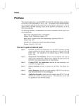
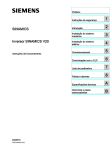
Physical dimensions
90 ㎜ (W)×80 ㎜ (D)×20 ㎜ (H)
( for detail, see the schematic in section 10 )
( no disturbing rays should directly enter receiver )
2 hours each in X, Y and Z directions
10. Schematic
Center of optical axis
Center of
optical axis
2-φ5
Mounting hole
Material :ABS (UL inflammable resin)
Color :Blue
- 34 -
DS4-2170
11. Settings and Procedure
11-1.Guarantee period
An year after delivery to the specified location
11-2.Scope of Guarantee
If any part of the product is found to have a fault attributable to us during the guarantee
period as defined above, it will be replaced or repaired at our cost.
This does not apply when:
① the product has been incorrectly handled or used by the user,
② the fault was caused for a reason not related with the product,
③ the product has been altered or repaired by the third party, or
④ the fault was caused by a natural disaster or another accident unavoidable by us.
We only guarantee the product itself and take no responsibility for any secondary damage
resulting from the use of the product.
12. Revision History
Date
Jan . 1999
Content of change
First issue
Responsibility
Development
section ( No.2 )
May. 1999
Jun. 1999
Specification for 3-meter setting distance is
Development
added
section ( No.2 )
Description of terminal resistance is added
( "B" )
Development
TRE setting and output mode are changed
Aug. 1999
"Caution in preparing a program" ( with
TO/FROM commands ) is added ( "C" )
Sep. 2000
Development
Changed to ensure compatibility with CC-Link
Ver. 1. 10 ( "D" )
Development
The following is the space
- 35 -