1
INSTALLATION INSTRUCTIONS
5
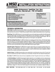
SECTION III FLYWHEEL AND TRIGGER PLATE
REMOVAL
Before installing the MSD Flywheel and Trigger Pickup
assembly, the stock magneto flywheel and stator plate must
be removed. Refer to your craft’s service manual for the
proper removal procedure.
TRIGGER PLATE ASSEMBLY
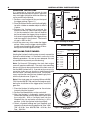
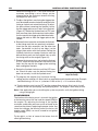
1. Assemble the trigger plate and pick-up assembly as
shown in Figure 8. Place the trigger plate assembly on
the bosses with the trigger on the side of the engine
where the wires normally exit the case (Figure 9). Screw
the supplied bolts and compression washers into the
case and lightly tighten to hold the trigger plate in the
center of the case's mounting pads.
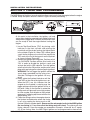
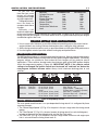
Kawasaki 750 installation: The engine case mounting
pads of the Kawasaki 750 must be drilled and tapped
(Figure 10).
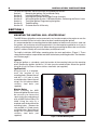
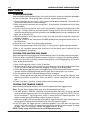
Figure 8 Assembling the Trigger
Plate.
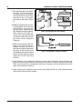
A. Drill and tap a hole on each pad 2.165" from
the center of the case. Drill and tap each hole
for a 6mm x 1mm allen head bolt using a No.
9 or 5mm drill bit and a 6mm x 1mm tap.
Each hole needs to be drilled 21mm deep.
B. Rotate the plate through the slotted positions
to ensure that the plate slides smoothly and
does not rock. If resistance is felt remove the
trigger plate and inspect the mounting
bosses for burrs and file flat if necessary.
Note: The PN 4312 Kawasaki 650/750 Trigger
Plate outside diameter is machined to fit the
mounting pads on the Kawasaki 750 engine.
When this plate is used on a Kawasaki 650
engine the trigger plate will have
approximately 1/16" play on each side.
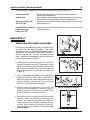
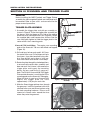
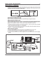
Figure 9 Mounting the Trigger Plate
Assembly.
2. Slide the Green trigger pickup wires through
the grommet. Install the grommet with wires
attached in the case and secure in place using
the stock mounting hardware. Place a small
amount of silicone sealer around the wires
where they enter the grommet.
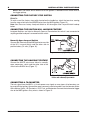
Figure 10 Modifying the Kawasaki 750 Case.
MSD IGNITION
• 12120 ESTHER LAMA, SUITE 114, EL PASO, TEXAS 79936 • (915) 857-5200 • FAX (915) 858-9241