1
INSTALLATION INSTRUCTIONS
3
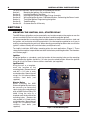
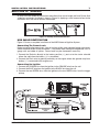
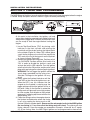
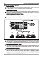
The following are suggested areas to install the mounting plate to your craft.
Kawasaki 650 SX
Kawasaki X2
Kawasaki 750 SX, SXi
SS, Xi, Xir, Zxi
Yamaha Blaster, SuperJet
VXR/WaveRunner,
Raider 701/760
Remove the stock electrical box and mount the plate to
existing mounting bosses.
Attach ignition mounting plate under the hood latch mounting
bolts. Mount coil above engine next to the steering arm.
Remove the stock electrical box and mount the plate to existing
mounting bosses.
Remove the stock electrical box and mount the plate to existing
mounting bosses.
SECTION II
INSTALLING THE SPARK PLUG WIRES
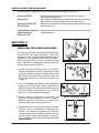
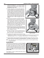
Each wire set includes two 90° dual crimp terminals,
two MSD Heli-Core Spark Plug Wires and a MiniStripper-Crimper. The MSD Mini-Stripper-Crimper is
supplied for assembling the MSD Spark Plug Wires.
Before using the tool it must be separated into two
parts. Separate it by bending the tool back and forth
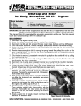
until the center breaks (Figure 2).
1. Locate the correct cutting groove of the MiniStripper-Crimper for your wire. One groove is larger
to accept the 8.5mm Super Conductor Wire. Insert
the wire from the long side of the crimper tool and
push it through until it is flush with the other side
(Figure 3).
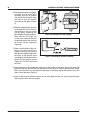
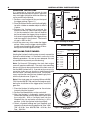
Figure 2 Separating the Mini-Stripper.
Figure 3 Stripping the Wire.
2. Press a single edge razor blade in the cutting groove
and push all the way down. Slowly rotate the wire
360° then remove the razor blade. Remove the wire
from the Crimper and slowly twist the cut end of
wire off in a counterclockwise direction.
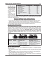
3. Before crimping the terminals to the wires the
terminals must be modified as shown in Figure 4.
Bend the terminal ears over 90° by using a pair of
regular needle nose or long nose pliers.
4. Position the wire in the terminal until the insulation
sleeve is about 1/8" beyond its crimping tabs.
Position the conductor between the conductor
crimps and use a pair of needle nose pliers to crimp
the tabs tightly against the conductor (Figure 5).
Make sure the conductor does not slide out and do
not overtighten.
MSD IGNITION
Figure 4 Preparing the Terminals.
Figure 5 Installing the Terminal.
• 12120 ESTHER LAMA, SUITE 114, EL PASO, TEXAS 79936 • (915) 857-5200 • FAX (915) 858-9241