1
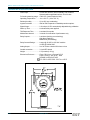
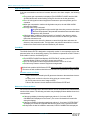
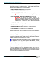
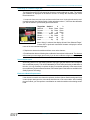
DESIGN MANUAL INSTALLATION -- OPERATION -- MAINTENANCE SERVICE MANUAL MODEL GIR902 NOVA-SENSOR ELITE™ COMBUSTIBLE GAS DETECTOR 70100 The information and technical data disclosed by this document may be used and disseminated only for the purposes and to the extent specifically a u t h o r i z e d b y S a f e t y S y s t e m s Te c h n o l o g y i n writing. Such information and technical data are proprietary to Safety Systems Technology and may not be used or disseminated except as provided in the foregoing sentence. 23282 Mill Creek Drive, Suite 215, Laguna Hills, California 92653 USA Te l 1 - 9 4 9 - 5 8 3 - 1 8 5 7 F a x 1 - 9 4 9 - 3 4 0 - 6 6 4 3 e - m a i l s u p p o r t @ s a f e t y s y s . c o m Blank Page Quick Finder MODEL GIR902 NOVA-Sensor ELITE™ Combustible Gas Detector GENERAL DESCRIPTION ............................................................... 902-1 TECHNICAL SPECIFICATIONS ....................................................... 902-2 SELECTING A LOCATION FOR THE GAS DETECTOR ................ 902-3 “ONE HOUR” INSTALLATION INSTRUCTIONS .............................. 902-4 1. MOUNT THE DETECTOR ELECTRONICS ENCLOSURE ................... 902-4 2. MOUNT THE REMOTE GAS SENSOR HEAD .................................... 902-4 3. OPEN DETECTOR AND REMOVE ELECTRONICS MODULE ............ 902-4 4. CONNECT EXTERNAL SENSOR HEAD TO THE DETECTOR .......... 902-5 5. CONNECT POWER AND ANALOG SIGNAL WIRING ....................... 902-6 6. CONNECT OPTIONAL REMOTE RESET SWITCH ............................. 902-6 7. CONNECT RELAY CONTACTS TO EXTERNAL EQUIPMENT .......... 902-6 8. SET RELAY CONTACT JUMPERS ...................................................... 902-7 9. SET LOW ALARM LATCHING OPERATION ...................................... 902-7 10. CHECK WIRING AND APPLY POWER .............................................. 902-8 11. CHANGE LOW AND HIGH ALARM SETPOINTS (OPTIONAL) ...... 902-8 12. BUMP TEST AND FUNCTIONAL CHECKOUT .................................. 902-8 ROUTINE OPERATION OF THE NOVA-Sensor ELITE ................. 902-9 PROTECTION MODE .................................................................................. 902-9 LOW GAS ALARM MODE ........................................................................ 902-9 HIGH GAS ALARM MODE ..................................................................... 902-10 FAULT MODE ........................................................................................... 902-10 MAINTENANCE REMINDER MODE ....................................................... 902-10 MAINTENANCE ...............................................................................902-11 MONTHLY “BUMP” TESTS ..................................................................... 902-11 CALIBRATION CHECK SCHEDULE ....................................................... 902-11 RECALIBRATION INSTRUCTIONS ......................................................... 902-11 CALIBRATING TO A DIFFERENT TARGET GAS ................................ 902-13 SENSOR REPLACEMENT ...................................................................... 902-13 ELECTRONICS MODULE REPLACEMENT ........................................... 902-13 SPARE PARTS & RECOMMENDED TEST EQUIPMENT ...................... 902-14 TROUBLESHOOTING ..................................................................... 902-14 CHECK CALIBRATION MESSAGE ....................................................... 902-14 SYSTEM FAULT MESSAGE .................................................................. 902-14 OTHER CALIBRATION MESSAGES ..................................................... 902-15 DRIFTING OR UNSTABLE % LEL READINGS .................................... 902-15 FALSE ALARMS ..................................................................................... 902-15 TRANSIENT INTERFERENCE OR POWER SURGES .......................... 902-15 WARRANTY INFORMATION .......................................................... 902-16 February, 2013 i Blank Page ii February, 2013 MODEL GIR902 NOVA-Sensor ELITE™ Combustible Gas Detector MODEL GIR902 NOVA-Sensor ELITE™ Combustible Gas Detector GENERAL DESCRIPTION Use the NOVA-Sensor ELITE Combustible Gas Detector to alert personnel when a flammable gas or vapor is accumulating in a protected area. This detector uses an infrared sensing element, and provides accurate measurements in atmospheres where traces of silicone or other poisoning agents may be present. Readings are unaffected by humidity or carbon dioxide. The display screen on the NOVA-Sensor continuously displays operating status and the actual concentration of gas in percentage of the Lower Explosive Limit (%LEL). This reading is converted to a standard 4-20 mA signal, which may be connected to any remote device for remote display or logging. Relay contacts are provided which transfer when the gas concentration exceeds the LOW ALARM and HIGH ALARM set points. Typical set points are adjusted by the installer upon installation and may be reset later by authorized personnel. The relays are suitable for controlling local HVAC equipment, alarm signal devices or for equipment shutdown. Fault relay contacts are also available which operate upon loss of power or internal failure of the unit. Model GIR902 Combustible Gas Detector The automatic calibration sequence is initiated by depressing the pushbutton switch located on the side of the enclosure. During calibration, step-by-step instructions are displayed on the NOVA-Sensor screen. There are no screwdriver or other manual adjustments required, and the calibration can be performed even in the presence of combustible gases. February, 2013 902-1 MODEL GIR902 NOVA-Sensor ELITE™ Combustible Gas Detector TECHNICAL SPECIFICATIONS Power Input .......................... 24 volts DC nominal, 180 mA standby, 240 mA alarm. Operates within specifications from 16 to 32 volts. Full scale measuring range .. 100% LEL (Lower Explosive Limit) Operating Temperature ......... -4 to +122° F (-20 to +50° C) Relative Humidity .................. 0% to 95% non-condensing Ingress Protection ................ IP40 to IP66. Depends on installed protection options. Signal Output ........................ 0.16 mA per % LEL automatically adjusted during calibration Warm-up Time ...................... 6 minutes after power applied T90 Response Time: ............ Less than 30 seconds Maintenance Interval: ........... 3 months for verification of performance only Relay Outputs: ...................... Low Alarm (latching or non-latching) High Alarm (latching) Malfunction (non-latching) Relay Contact Ratings: ......... 6 amps @ 28 VDC or 300 VAC resistive 1/8 HP @ 120/240 VAC Analog Output: ..................... 0 to 20 mA into a load of 600 ohms or less Conduit connection ............... ¾ inch NPT thread. Weight: ................................. 6.75 pounds (2.15 kg) Electronics Enclosure ........... Class I Division 1 Groups B,C,D Class I Zone 1 AEx d IIC, IP66 DEMKO 01ATEX015742U II 2 GD Ex dIIC IP66 -20°C to +60°C Mounting Dimensions 902-2 February, 2013 MODEL GIR902 NOVA-Sensor ELITE™ Combustible Gas Detector SELECTING A LOCATION FOR THE GAS DETECTOR To insure the fastest possible detection of leaking gases, the location of the sensor is important. Lighter than air gases tend to accumulate at the highest point in an enclosed space, whereas heavier than air gases will accumulate at the lowest point in the room. For sensors located out of doors or in very large enclosed spaces, try to located a sensor near any expected source of leaks (such as pumps, valves or pipe fittings), taking the gas weight into consideration. Also consider the effect of wind or forced air cooling at the sensor location. The gas sensor will never respond if air currents blow the gas away from the sensor. Preferred orientation of the sensor is with the porous face of the sensor pointing down, as shown in the pictures. If necessary, it may be installed at an angle or horizontally. The sensor must never be installed pointing upwards. Lighter than air combustible gases (sensor mounted above leak point) For lighter than air gasses, the sensor should be located above the spot where a leak is likely or at the highest point within an enclosure. Combustible Gas Methane Density 0.6 Lower Flammable Limit 5.0% Gases with weights near that of air (Density of air = 1.00) These gases mix readily with air, so sensor location is not as critical, but sensor should still be near the expected leak point for fastest response. Combustible Gas Ethane Density 1.0 Lower Flammable Limit 3.0% Heaver than air combustible gases (sensor mounted below leak point) For heavier than air gasses, locate the sensor below the expected leak. However, do not locate the sensors closer than 1 foot to a floor to prevent damage from water, dust, etc. ! Combustible Gas Propane Butane Pentane Hexane LPG/LNG Density 1.6 2.0 2.5 3.0 Lower Flammable Limit 2.1% 1.9% 1.5% 1.1% NOTE: Data in above tables is from reliable sources that are believed to be accurate, but is not guaranteed by Safety Systems Technology. Lower Flammable Limit is the concentration of the gas below which burning does not occur, expressed as percent by volume in air. February, 2013 902-3 MODEL GIR902 NOVA-Sensor ELITE™ Combustible Gas Detector “ONE HOUR” INSTALLATION INSTRUCTIONS The Model GIR902 Combustible Gas Detector is shipped fully assembled and pre-calibrated to the full scale range of combustible gas that you have specified with your order. It can be installed and be fully operational in less than one hour. Various protection accessories required for use in hostile environments are already installed on some detectors. 1. Mount the Detector Electronics Enclosure Secure the electronics to a wall or bracket, using bolts through the two mounting holes. Locate the unit at a convenient place where the viewing screen and LED’s can be easily seen through the window on the front of the enclosure. Most NOVA-Sensor ELITE detectors are shipped with the sensor preinstalled onto the electronics housing as shown here. Electronics Enclosure 2. Mount the Remote Gas Sensor Head For 2-piece gas sensors only, mount the remote sensor in the location chosen for best and fastest response to leaking gas, as explained on the previous page. Lighter than air gases, sensor mounts on or near ceiling of enclosure. Heavier than air gases, sensor mounts about 1 foot (30 cm) above floor or ground. Preferred orientation is with the porous metal sensing face pointed downward. Never point the sensor face upward to insure that no moisture or dust collects on the sensor face to reduce sensitivity and damage the sensor. 3. Open Detector and remove Electronics Module Loosen the hex head set screw on detector cover (a 7/64 inch hex wrench is required) and turn cover counter clockwise to remove. Cover Lock Screw Remote Sensor Use a small screwdriver inserted under the edge of the electronics module in the 3 locations marked “pry up” to loosen the module from the connector and remove it from the enclosure. Remove Electronics 902-4 February, 2013 MODEL GIR902 NOVA-Sensor ELITE™ Combustible Gas Detector 4. Connect external Sensor Head to the Detector The sensor head, if installed on the electronics housing, is pre-wired to the NOVA-Sensor ELITE electronics by SST at the factory. If remote sensor is used, three conductors are required between the Sensor and the NOVA-Sensor electronics. These wires will be carrying the 24 volts DC operating power to the sensor and also return the 4-20 mA signal from the sensor to the electronics. The wire must meet the following specifications: All 3 conductors must be same wire size and length Should be installed in metal conduit or be shielded or screened cable with the shield/screen connected to the chassis screw inside the electronics housing. Avoid running the cable close to high powered cables or equipment or close to radio transmitters or antennas. Combustible Sensor Connections The wire size and total DC resistance of the wires is not critical, but for reliable installations we recommend a wire size of 18 AWG (0.75 mm2) or larger. ! IMPORTANT: Any electrical conduit connected to the NOVA-Sensor ELITE electronics enclosure must have a conduit seal installed within 18 inches (45.7 cm) of the enclosure. February, 2013 902-5 MODEL GIR902 NOVA-Sensor ELITE™ Combustible Gas Detector Typical Power and Signal Wiring 5. Connect Power and Analog Signal Wiring A typical installation is shown in this drawing. This setup uses three wires between the NOVA-Sensor ELITE and the associated control modules. These wires carry the 24 VDC operating power for the sensor, and transmit the 20 mA signal to the controls. The wires should be shielded (screened) or installed in metal conduit to prevent undesirable noise pickup. Note that the black wire shown in the drawing provides the return path for both the 24 volt operating power and the 4-20 mA analog output. ! IMPORTANT: Any electrical conduit connected to the NOVA-Sensor ELITE electronics enclosure must have a conduit seal installed within 18 inches (45.7 cm) of the enclosure. 6. Connect optional remote RESET Switch The integral MODE pushbutton on the NOVA-Sensor ELITE housing can be used to clear any relays or alarms in the NOVA-Sensor ELITE which have been latched when activated. Pressing the button will cause the latched relays to clear. The alarm setpoints will also be momentarily displayed. An optional remotely located pushbutton switch can be wired to the terminal marked RESET. This should be a normally open contact, and should connect the reset terminal to 24VRET (COMMON) to reset the detector when actuated. The remote RESET button, when active for 1 to 3 seconds will clear any latched relays. 7. Connect Relay Contacts to external equipment The internal alarm and fault relay contacts can be used to provide signals to other pieces of equipment. Typical applications would be to activate audible and visual alarm signals to alert personnel in the local area. Or these contacts may be used to shut down critical equipment or to report conditions to a data logging system. These contacts may be set to be either normally open (NO) of normally closed as described below. Connect 2 wires between external equipment and each of the below listed terminal pairs. LOW ALM & LA COM HI ALM & HA COM FAULT & FLT COM 902-6 Contact transfers when LOW Alarm setpoint is reached Contact transfers when HIGH Alarm setpoint is reached Contact transfers when detector is in FAULT condition February, 2013 MODEL GIR902 NOVA-Sensor ELITE™ Combustible Gas Detector 8. Set Relay Contact Jumpers Jumpers on the detector electronics module lower most circuit board allow relay contacts to be set as normally open or normally closed. Low and High Alarm Relay Contacts The factory jumpers are shipped connecting the 2 NO pins together. Contacts will be open when there is no gas alarm, and will close when a low or high gas alarm is detected. Low Alarm Jumper High Alarm Jumper Remove jumper plug from the NO pins and reinstall on NC pins to set this contact to be normally closed. Fault Relay Contacts The factory jumper is shipped connecting the 2 OF (Open on Fault) pins together. The fault contact will be closed when there is no fault detected in the gas detector. The fault contact will open when any internal fault condition occurs in the gas detector. The fault contact will also open if the 24 volt DC power supply to the detector is interrupted. Fault Jumper ! Remove jumper plug from the OF pins and reinstall on CF (Closed on Fault) pins to set the fault contact to close when a fault or loss of power is detected. There are two additional jumpers factory installed at the positions marked “TOX”. Do not remove or change these jumpers nor move them, as they are required for proper operation of this detector. 9. Set Low Alarm Latching Operation User Option Switch number 4 sets the operation of the LOW alarm indicator LED and relay. Switch 4 DOWN sets Low Alarm NON-LATCHING. The low alarm will automatically reset whenever the gas level falls below the set point. User Options Switch Switch 4 UP selects LATCHING mode for the LOW alarm. You must press the MODE button on the detector housing or use the remote RESET input to clear the alarm. Note: The HIGH Alarm is always latching and cannot be set to non-latching mode. User Options Switch 1, 2 and 3 are preset at the factory to match the factory calibration of your NOVA-Sensor ELITE. Do not change these switches unless you are recalibrating the detector for a different target gas. Refer to Recalibration Instructions in this manual. February, 2013 902-7 MODEL GIR902 NOVA-Sensor ELITE™ Combustible Gas Detector 10. Check Wiring and Apply Power ! WARNING: Verify that there are no combustible gases present before power to the NOVASensor ELITE is turned on. Activate the source of 24 volt DC operating power for the detector and use a voltmeter to verify that voltage is available at terminals marked +24V and 24VRET. Plug the electronics module into the connectors in the enclosure and push down on the 3 screw heads to be sure the module is completely pushed into the connectors. The module will display: Model GIR902 followed by version number of the firmware Sensor Warmup .... 300 to 0 seconds 0 %LEL Methane (or other gas name) The green POWER indicator will blink slowly to indicate unit is fully operational 11. Change LOW and HIGH Alarm Setpoints (Optional) ! The cover must be removed from the detector to access the UP and DOWN buttons to change the alarm setpoints. The cover must not be removed when there is any flammable gases or vapors present. To display the current setpoints, momentarily press the button on the side of the enclosure or the MODE button on the electronics module. The default factory settings are “20% LEL LOW ALARM SET” and “50% LEL HIGH ALARM SET”. To change the setpoints, depress either the UP or DOWN button to display “SET LOW ALARM POINT” and use buttons to adjust setpoint as desired. Release button, wait for “SET HIGH ALARM POINT”, then adjust as desired. Replace front cover on detector housing and tighten lock screw. 12. Bump Test and Functional Checkout As a final check to be sure that the NOVA-Sensor ELITE is working properly, briefly expose the gas sensor to a weak concentration of a combustible gas. Do not use pure gas, as this high concentration would shorten the life of the sensor. The 50% LEL gas mixture that is used for calibrating the sensor may be used for the bump test, but gas mixed to that precision is not required. The sensor should be exposed to the gas only long enough to see that it is responding to the gas. By most definitions, a bump test is a brief exposure of the sensor to gas in order to verify that the sensors respond and the instrument alarms function accordingly. The bump test, by this definition, does not check the accuracy of the instrument. 902-8 February, 2013 MODEL GIR902 NOVA-Sensor ELITE™ Combustible Gas Detector ROUTINE OPERATION OF THE NOVA-Sensor ELITE The NOVA-Sensor ELITE is designed to provide protection of personnel and property from gas leaks 24 hours a day, 7 days a week with no regular intervention required. Protection Mode This is the normal operating mode, and the NOVA-Sensor ELITE will be in this mode when all conditions are normal. The lighted blue background on the display screen will be dimmed to conserve power, but the digital display of the actual concentration of the target gas will be readable, even if the detector is located outdoors in bright sunlight. The green POWER indicator will be illuminated, and will occasionally blink as a confirmation that the microprocessor is continuing to check the area for gas. In protection mode, all relay contacts are in the normal, non-alarm and non-fault condition, and the detector will transmit a 4.0 mA signal to any connected external equipment. Press and release the button on the side of the enclosure to: Restore the screen illumination to full brightness Display the gas concentration that will activate the LOW ALARM Display the gas concentration that will activate the HIGH ALARM The detector will then return to normal operation. Low Gas Alarm Mode When gas is starting to accumulate in the protected area, the following occur: The present gas concentration is displayed (The screen will remain at half brightness during this time) The 4-20 mA signal to external equipment increases to report the present gas concentration When gas concentration reaches the low alarm set point, the SCREEN FLASHES and the red LOW ALARM indicator also flashes. The low alarm relay is activated A typical application might use this low alarm relay contact to activate an exhaust fan to try to remove the leaking gas from this location. If gas concentration goes down below the low alarm set point, the red alarm indicator is extinguished and the screen stops flashing, but remains at full brightness until the gas concentration returns to zero. If the red alarm indicator and the screen do not stop flashing when the gas concentration is below the low alarm set point, the detector has been configured with a latching low alarm. In that case, you must push the button on the side of the detector to cancel the low alarm and return the detector to the protection mode. The low alarm may also be canceled from a remote location if the reset function has been installed in your detector.. At zero gas concentration, the screen returns to half brightness and the detector returns to normal protection operation. ! ! February, 2013 902-9 MODEL GIR902 NOVA-Sensor ELITE™ Combustible Gas Detector High Gas Alarm Mode If the gas concentration continues to increase above the low alarm setpoint, the following occur: The present gas concentration is displayed (The SCREEN FLASHES and the LOW ALARM indicator will remain flashing during this time due to the low gas alarm) The 4-20 mA signal to external equipment increases to report the present gas concentration When gas concentration reaches the high alarm set point, the red HIGH ALARM indicator also flashes. The high alarm relay is activated A typical application might use this high alarm relay contact to shut down all electrical equipment in the protected area and activate evacuation alarm signals to alert personnel. A high gas alarm condition is always locked in or “latched” in the detector, and the high alarm indicator and the screen will continue to flash even after the gas concentration has returned to zero. Push the button on the side of the detector to cancel the high alarm and return the detector to the protection mode. The high alarm may also be canceled from a remote location if the reset function has been installed in your detector. ! Fault Mode The NOVA-Sensor ELITE is designed to continually monitor it’s own operation and to alert personnel when it is not functioning properly. This condition is reported as a FAULT. When a fault condition is active, the following occur: The SCREEN FLASHES and displays SYSTEM FAULT, and the yellow FAULT indicator flashes (if failure is not due to power source failed) The 4-20 mA signal to external equipment decreases to 2.0 mA or 0.0 mA The fault relay contact to external equipment changes state ! While in fault mode the NOVA-Sensor ELITE might not be able to report an alarm condition. The source of fault conditions should be corrected as soon as possible for safety reasons. Possible causes of a Fault Sensor head failure caused by the IR gas sensor element or the transmitter electronics. An open-circuit or short-circuit on the wiring going to a remote sensor 24 volt DC power source out of range or failed Failure of the electronic circuits inside the NOVA-Sensor ELITE itself Maintenance Reminder Mode We recommend a monthly test of the NOVA-Sensor ELITE as explained in the Maintenance section of this manual. The following reminders may be displayed when additional service is recommended: If the sensor display is showing negative gas values of -5 or lower, CHECK CALIBRATION is displayed on the screen. (The screen illumination will remain dim during this display) If the sensor display is showing negative gas values of -10 or lower, SYSTEM FAULT will display, the screen back light will flash and the yellow FAULT indicator will flash. 90 days after the last full calibration was made, CHECK CALIBRATION is displayed. 902-10 February, 2013 MODEL GIR902 NOVA-Sensor ELITE™ Combustible Gas Detector MAINTENANCE Monthly “Bump” Tests We recommend that a short performance test be performed at least every 30 days to verify that your NOVA-Sensor ELITE is operational. This is commonly called a Bump Test in the industry. During this test, you expose the detector to a small amount of test gas, just enough to see that the sensor is reading the gas concentration. It is not necessary to perform a complete recalibration of the detector. During the bump test all of the detector’s outputs (analog and relay contacts) may be activated. Before starting, notify affected personnel and bypass any shutdowns if required. You may use calibrating test gas (50% LEL) or any other test gas at any concentrations less than 100% LEL. Expose the sensor head to the bump gas. Watch for the concentration readings to be displayed on the detector screen. You do not need to continue beyond this point, you just want to be sure that there is a response. If you have test gas with concentrations higher than the alarm trip points, you may leave the gas on until they activate if desired. Calibration Check Schedule The NOVA-Sensor ELITE has been pre-calibrated to the desired target at the factory, and no further calibration will normally be required when it is initially installed. Under normal operating conditions, SST infrared gas detectors do not require regular recalibrations. However, you can verify calibration at any time To verify, expose the detector to the same 50% LEL calibration gas as was used for the original calibration. 90 days after the last calibration of the detector was made, the message CHECK CALIBRATION will be displayed on the screen. This will not effect the normal operation, and the NOVASensor will continue in normal protection mode using the existing calibration data. But we do recommend chacking the calibration as explained in the above paragraph. Checking the calibration will reset the check calibration message. Recalibration Instructions Calibration will take care of changes in sensor performance and drift. The automatic calibration procedure provides the NOVA-Sensor ELITE with reference points needed to accurately measure gas levels. During the calibration procedure, clean air as well as calibrated test gas are applied to the detector. If clean air cannot be assured, you may need to “purge” the sensor with clean air from a gas bottle. DO NOT USE Nitrogen to purge the sensor, false readings may result! The calibration can be performed by one person with the NOVA-Sensor ELITE operating in the hazardous area. No manual adjustments are required for calibration. ! Calibration gas with a concentration of exactly one-half of the rated full scale of the NOVA-Sensor ELITE mixed with air is required for the calibration procedure (e.g. 50% LEL balance air calibration gas for a 100% LEL combustible gas sensor). February, 2013 902-11 MODEL GIR902 NOVA-Sensor ELITE™ Combustible Gas Detector Calibration Procedure The calibration procedure is initiated by depressing and holding depressed the MODE pushbutton located on the side of the detector enclosure. This will start the sequence of easy calibration instructions displayed on the screen, as listed below. 1. HOLD FOR CALIBRATION MODE while button is depressed. 2. TO START CALIBRATION RELEASE BUTTON NOW. 3. CALIBRATION MODE FINDING ZERO...WAIT storing zero reference point WARNING: If sensor is exposed to any combustible gases during this step, the calibration will not be correct. ! 4. CHECK GAS PRESSURE ... APPLY 50% LEL METHANE waiting for test gas WARNING: If calibration gas cylinder pressure is low, there may not be enough gas in the cylinder to accurately calibrate the detector. Abort calibration immediately by pressing mode button 2 times. Calibration will not be correct if you continue calibration procedure with insufficient gas. ! 5. GAS DETECTED...WAIT measuring the test gas concentration 6. REMOVE GAS...WAIT to allow test gas to dissipate from inside of sensor 7. CALIBRATION COMPLETE calibration data saved for use until next calibration 8. 0% LEL METHANE NOVA-Sensor ELITE returns to normal operation During the calibration process, the 4-20 mA output is set to 2 mA and the relay outputs will not be activated. Failed or Incomplete Calibrations: The NOVA-Sensor ELITE will wait for up to 5 minutes for gas to be applied during the calibration procedure. If no gas is detected within the 5 minutes, the calibration will be aborted and the message CALIBRATION FAILURE, USING PRIOR CALIBRATION DATA is displayed. The NOVA-Sensor ELITE will then return to normal operation. ! You may abort or cancel a calibration procedure at any time by momentarily depressing the MODE button 2 times. The message CALIBRATION CANCELED, ORIGINAL VALUES WILL BE USED is displayed. You may also abort the calibration by interrupting the 24 VDC power to the detector. Possible causes for incomplete calibration are: 1) Gas sensor head failure due to liquid intrusion. 2) Calibration gas applied at wrong time. Gas applied during step 3 above (i.e. too early, during clean air sampling) will result in negative displays and inaccurate readings. If the gas is applied too late (which may occur due to the pipe length when remote sensors are used) it may not reach significant levels before the 5 minute time-out. 902-12 February, 2013 MODEL GIR902 NOVA-Sensor ELITE™ Combustible Gas Detector Calibrating to a different Target Gas The NOVA-Sensor ELITE will respond to almost any combustible gas or vapor. The existing gas calibration is displayed on the detector screen. To change the calibration gas, follow these instructions. 1. Loosen the front cover set screw and remove the front cover. Unplug the electronics module and locate the User Options Switch. Option switches number 1, 2 and 3 set the calibration gas. Set the switch to your desired gas as listed below. User Options Switch Target Gas Switch 1 Methane ............. Down Propane ................. Up Butane .................... Up Hexane ............... Down Ethane .................... Up Pentane .............. Down Other ...................... Up 2 Down Down Up Down Down Up Up 3 Down Down Down Up Up Up Up When “Other” is selected, the display will read “User Selected Target”. Contact SST to purchase customized firmware to display the actual name of the user selected target gas. 2. Replace the electronics module and front cover on the detector. 3. Recalibrate the detector following the recalibration instructions in this manual. The detector will not read your new target gas correctly if you do not recalibrate using the new target gas. Sensor Replacement After many years of use, the sensing element may age to the point where it will no longer be able to calibrate properly. This will be indicated by a FAULT after performing a calibration. At this time, it is only necessary to replace the plug-in transmitter assembly in the sensor head, then recalibrate. Replacement transmitters, listed under Spare Parts below are available from Safety Systems Technology. Electronics Module Replacement If the electronics module ever has to be replaced, the User Options Switch settings and relay contact jumper settings on the old module should be set on the new module. After installing the new module, you must perform a recalibration to match the module to the existing sensor head. February, 2013 902-13 MODEL GIR902 NOVA-Sensor ELITE™ Combustible Gas Detector Spare Parts & Recommended Test Equipment The most common spare or replacement parts, available from Safety Systems Technology are listed below. For purchase these parts, contact your local SST distributor, or contact us at [email protected]. Order No. Description 40900-25-2 40900-25-3 40900-25-5 40900-25-7 40900-25-8 Plug-in transmitter module and sensor element, Methane Plug-in transmitter module and sensor element, Propane Plug-in transmitter module and sensor element, Butane Plug-in transmitter module and sensor element, Ethane Plug-in transmitter module and sensor element, Pentane 40902-32 Electronics Module for Model GIR902 NOVA-Sensor ELITE. To insure that we provide the correct version of this module, please provide the exact part number (Part) from the label on your electronics module, or the serial number (SN) visible through the NOVA-Sensor window. 867-XX Model 867 Detector Test & Calibration Gas kit (Replace XX with name of test gas desired) TROUBLESHOOTING Check Calibration message The sensor head has lost some sensitivity, resulting in display values of less then 0 %LEL. You must perform a recalibration procedure to correct this. If the recalibration does not result in a 0 %LEL reading, the sensor head has probably been damaged. Replace the sensor head. System Fault message This message may appear when the existing electronics module in the detector is replaced with a different module. Perform a complete recalibration procedure to correct this problem. The sensor head may have failed. The transmitter module in the head must be replaced, followed by a recalibration of the detector. The 24 volt DC power supplied to the detector may be less than 16 volts or greater than 32 volts. Replace or service the power supply. Although not a regular occurrence, it is possible that an internal failure has occurred in the detector electronics module. We suggest you purchase a replacement electronics module, then return the failed electronics module to SST for repairs. The repaired module can then be placed in your stock for future use. 902-14 February, 2013 MODEL GIR902 NOVA-Sensor ELITE™ Combustible Gas Detector Other Calibration messages The below listed messages occur during recalibrations. To stop the calibration process at any one of these steps, just push the large mode button on the side of the enclosure two times. The NOVA-Sensor will return to normal operation using the previous calibrations. HOLD FOR CALIBRATION MODE RELEASE BUTTON NOW FINDING ZERO...WAIT APPLY 50% LEL GAS GAS DETECTED...WAIT REMOVE GAS...WAIT CALIBRATION COMPLETE Drifting or unstable % LEL readings Check the 3 wires between the sensor head and the electronics module. Screw terminals, crimped connectors or wire nuts on these wires must be extremely tight to maintain the low resistance connections between the head and the electronics. Also check the jumper on the two “C” pins of the electronics module to be sure that the jumper plug is securely seated on the pins. False Alarms If you are having an unreasonable number of alarms, try to verify the gas concentration near the detector using a personal gas monitor. If there is no gas, or very little gas, recalibrate the NOVA-Sensor ELITE. If alarms still occur, the sensor head has probably lost sensitivity, and the detector has tried to compensate by increasing the amplifier sensitivity. In that case, the sensor head should be replaced and a new calibration performed. Transient Interference or Power Surges Transient voltage suppressors in the NOVA-Sensor ELITE protect the electronics from transients that may be induced into the field wiring during operation. The terminal marked CHASSIS in the NOVA-Sensor is factory connected to the 24VRET terminal to complete the suppression path. In areas where there are severe high energy transients, including those caused by lightning, you may get more effective transient suppression by removing the factory jumper and connecting the CHASSIS terminal to the earth grounding screw in the detector enclosure. ! WARNING: The above change can be made only if the enclosure is firmly connected to earth ground and the voltage measured between the earth ground screw and the 24VRET terminal is not greater then 2.0 volts DC. February, 2013 902-15 MODEL GIR902 NOVA-Sensor ELITE™ Combustible Gas Detector WARRANTY INFORMATION Safety Systems Technology, Inc. warrants its gas detection products to be free of defects in materials or workmanship and will repair or replace without charge any detector that is found to be defective for one year after the date of manufacture. Gas detection elements that are damaged by exposure to moisture are not covered by this warranty. Further, detection elements that have failed due to incorrect hookup or have been subjected to an over current are not covered by this warranty. For NOVA-Sensor ELITE Gas Detectors - Electronic Components ONLY • First Two Years - Full Replacement • Year 3 - SST Covers 75% of Replacement Charge* • Year 4 - SST Covers 50% of Replacement Charge* • Year 5 - SST Covers 25% of Replacement Charge* * Replacement charge is based on the current list price of the unit at time of claim. Safety Systems Technology, Inc. (SST) reserves the right to make the final determination of the nature of and responsibility for defective or damaged equipment. Equipment that has been repaired or modified by the user, damaged as the result of an accident, incorrectly installed, or used in an application or environment for which it was not intended is not covered by this warranty. Safety Systems Technology, Inc. (SST) responsibility under this warranty shall be limited to the repair or replacement of the defective equipment at its option when it is returned to the factory transportation prepaid. The defective unit will be repaired or replaced free of charge to the customer and returned transportation prepaid. In all cases, this warranty is limited to the cost of the equipment. Please consult the Limited Warranty and Product Return Procedure certificate at http://www.safetysys.com/warranty.pdf for additional terms and conditions. ! WARRANTY EXPIRATION DATE: Look for the serial number (SN) visible through the viewing window on the electronics enclsoure. The first 2 digits of the serial number are the year of manufacture, the next 2 digits are the week of manufacture. For number SN1242001, the product was manufactured in the 24th week of year 2012 (October 19, 2012). The warranty would expire 5 years from that date (October 18, 2017). 902-16 February, 2013