1
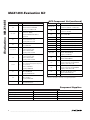
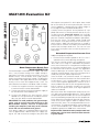
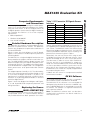
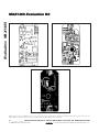
19-1032; Rev 0; 5/08
MAX1455 Evaluation Kit
The MAX1455 evaluation kit (EV kit) demonstrates resistive element sensor compensation and calibration using
the MAX1455 and a computer. The kit includes an
assembled and tested PCB, which is available with a
factory-calibrated sensor (MAX1455EVKIT-CS) or without a sensor (MAX1455EVKIT-NS). The software and
computer are not required for performing the initial performance evaluation of the sensor option since the EV
kit is already compensated. A 10-pin ribbon cable connects the EV board to a serial-key adapter,
MAX1452KEY, that plugs into a computer serial port,
allowing the board to be evaluated inside an environmental chamber. The software requires a PC compatible with Windows® 95/98/2000/XP.
Windows is a registered trademark of Microsoft Corp.
Features
♦ Proven PCB Layout
♦ Convenient On-Board Test Points
♦ Fully Assembled and Tested
♦ Optional Pressure Sensor (MAX1455EVKIT-CS)
♦ Factory-Calibrated Over Temperature
(MAX1455EVKIT-CS)
♦ LabVIEW®-Based Software
LabVIEW is a registered trademark of National Instruments, Corp.
Ordering Information
PART
TYPE
MAX1455EVKIT-CS
EV Kit
MAX1455EVKIT-NS
EV Kit
MAX1452KEY*
Serial Key Adapter
*MAX1452KEY is also used for MAX1455EVKIT and is included
in MAX1455EVKIT package.
EV Kit Component List
DESIGNATION
QTY
DESCRIPTION
C1
1
470µF 10V electrolytic capacitor
C2, C4, C6
3
0.1µF X7R ceramic capacitors
C3, C5
2
1µF X7R ceramic capacitors
D1
1
5.6V Zener diode
D2
0
Dual diode, not installed
J1
0
2-pin header, not installed
J2
J3
J4
P1
-CS
0
2-pin header, not installed
-NS
1
2-pin header—shorted
1
2-pin header
-CS
1
2-pin header—shorted
-NS
0
2-pin header, not installed
1
10-pin header
P2, P3, P4
3
4mm banana sockets;
connect +5V, GND, OUT
R1
1
10Ω ±5% resistor
R2
1
4.7kΩ ±5% resistor
R3
1
10Ω ±5% resistor
R4
1
30Ω ±5% resistor
S1
1
NovaSensor (Fremont, CA)
NPH-8-100GH
(8-pin TO package, 100kPa gauge)
S2
0
Unused, alternate sensor site
DESIGNATION
QTY
DESCRIPTION
S3
1
8-pin DIL header, alternate sensor
connector
SP1–SP4
4
Split pads;
cut tracks to allow connection of
sensor at S3
SP5
1
Split pad;
configure on-board op amp as buffer;
cut tracks to allow use of op amp
U1
1
MAX1455AAE
U1
1
MAX1455AAP
KEY Component List
DESIGNATION
C1
C2, C3, C5
C4
QTY
DESCRIPTION
1
220µF 10V electrolytic capacitor
(radial lead)
Panasonic ECE-A1AKA221
Digi-Key P832-ND
3
0.33µF ±10%, 25V X7R ceramic
capacitors* (1206)
Taiyo Yuden TMK316BJ334KF or
equivalent
Murata GRM319R71E334K
1
0.047µF ±10%, 50V X7R ceramic
capacitor (1206)
KEMET C1206C473K5RACTU
Digi-Key 399-1246-1-ND
________________________________________________________________ Maxim Integrated Products
For pricing, delivery, and ordering information, please contact Maxim Direct at 1-888-629-4642,
or visit Maxim's website at www.maxim-ic.com.
1
Evaluates: MAX1455
General Description
Evaluates: MAX1455
MAX1455 Evaluation Kit
KEY Component List (continued)
DESIGNATION
QTY
C6
C7–C12
D1
D2
6
0.1µF ±10%, 25V ceramic
capacitors* (0805)
Murata GRM21BR71E104K or
equivalent
1
Switching diode 30V, 0.2A
Panasonic MA715-(TX)
Digi-Key MA715CT-ND
3
J3
J1–J4
DESIGNATION
1
1
J1, J2, J4
DESCRIPTION
10µF 10V tantalum capacitor (R case)
Panasonic ECS-T1AX106R
Digi-Key PCS2106CT-ND
4
Shunts (J1 = open, J2 = shorted, J3
pins = 2/3 shorted (lower two pins),
J4 = shorted)
Sullins SSC024AN
Digi-Key S9002-ND
1
Low-profile header 2 x 5 0.1 centers
3M 2510-6002UB
Digi-Key MHB10K-ND
P2
1
9-pin D-subconnector
AMP 747905-2
Digi-Key A2047-ND
Q1, Q2
2
Power MOSFETs (8-pin SO)
Fairchild NDS8958
P1
Q3, Q5, Q6
3
Q4
1
pnp differential transistor
Panasonic XP2401
Q7
1
n-channnel MOSFET
Zetex ZVN4106F
R1
1
1Ω 1W resistor (2512)
2-pin headers, gold (0.1in centers)
(cut from 36-pin strip)
Sullins PZC36SAAN
Digi-Key S1011-36-ND
1
DESCRIPTION
npn transistors
Panasonic UN5214 or UN5215CT
Diode BAR74
Zetex BAR74ZX
3-pin header, gold (0.1in center)
(cut from 36-pin strip)
Sullins PZC36SAAN
Digi-Key S1011-36-ND
QTY
R2, R3
2
110Ω 1/8W resistors (1206)
R4
1
470Ω 1/8W resistor (1206)
R5, R6
2
47kΩ 1/8W resistors (1206)
R7
1
390kΩ 1/8W resistor (1206)
R8
1
10kΩ 1/8W resistor (1206)
R9, R10
2
2.2kΩ 1/8W resistors (1206)
RL1, RL2
2
Ultra-reed relays
Hamlin HE3621A0510
Digi-Key HE207-ND
U1
1
Op amp (SOT23)*
Maxim MAX4490AUK
U2
1
IC, hex inverter (14 SO)
Texas Instruments SN74HC04DR
Digi-Key 296-1189-1-ND
U3
1
Quad 2 input (14 SO)
Texas Instruments SN74HC00DR
Digi-Key 296-1187-1-ND
U4
1
RS-232 +5V driver/receiver*
Maxim MAX3387ECUG
—
1
MAX1452KEY serial board, PCB
*Indicates that part is normally consigned by Maxim.
Component Suppliers
SUPPLIER
Digi-Key Corp.
PHONE
800-344-4539
WEBSITE
www.digikey.com
KEMET Corp.
864-963-6300
www.kemet.com
Murata Electronics North America, Inc.
770-436-1300
www.murata-northamerica.com
Quest Components
626-333-5858
www.questcomp.com
2
_______________________________________________________________________________________
!
WARNING! Do NOT interconnect the EV board and the
KEY while jumper J4 is in place, as this will permanently damage
the KEY when power is applied to the EV board.
MAX1455 Evaluation Kit
•
Printout of compensation test data (MAX1455EVKIT-CS
only)
Required Equipment
•
Five samples of the MAX1455
•
Straight-connected serial cable for connecting the
KEY and PC
•
Precision-regulated +5V power supply
•
Multimeter with at least five significant digits
•
Sensor pressure source
Overview
Procedure
4) Connect a DVM between OUT and GND.
The objective of the EV kit is to allow the user to learn
how to program the ASIC using a hands-on approach.
To do this, users are encouraged to compensate their
own sensors using the EV kit along with the provided
software. This kit is intended to be used by engineers
familiar with resistive element sensors and their compensation techniques.
The purpose of the MAX1455EVKIT-CS is to demonstrate
the capabilities of the MAX1455 in compensating a typical resistive element sensor. To assist the user in quickly
evaluating the ASIC, the board has been precompensated using a generic, low-pressure sensor such as the
NovaSensor NPH8-100G.
5) Determine whether the EV board will run in analog
or digital mode:
Factory setting of the -CS type is analog mode.
Factory setting of the -NS type is digital mode.
In the case of the MAX1455EVKIT-CS, the test data printout included in the EV kit is specific to the particular EV
board enclosed in the kit. Both the test data and the EV
board contain a serial number for identification.
Use the following quick-start procedure to operate and
evaluate the factory calibration accuracy of a MAX1455
EV board with sensor option.
1) Download and install the MAX1455 EV kit software
on your PC.
2) Run Port98nt.exe (from the START menu or
MAX1455 folder) to load the device driver for PC IO
communication.
3) Connect a 5V power supply to the +5V and GND
terminals on the EV kit.
6) For analog mode, make sure jumper J2 is removed
and jumper J4 is present. Note: It is not possible to
communicate with the MAX1455 while in analog
mode.
7) For digital mode, make sure that jumper J2 is present
and jumper J4 is removed before applying power to
the EV board. In addition, make sure that the 10-pin
ribbon cable connects the EV board to the serial communication module and that the 9-pin connector on
the serial module is connected to the PC either directly
or through a straight-connected serial cable.
MAX1455 EV Kit Contents
The MAX1455EVKIT-CS is shipped fully temperature compensated from -40°C to +125°C. The
MAX1455EVKIT-NS version of the EV kit is shipped
without a sensor. Additional material may be included
in your EV kit, which are not listed below.
• MAX1455 EV board
•
MAX1452KEY interface adapter
•
10-pin ribbon cable for connecting the KEY and EV
board
•
Computer interface adapter ribbon interconnect cable
Initial Setup
See the MAX1455 EV board (Figure 1). Four configuration jumpers, J1–J4, are provided to make the EV board
adaptable to a wide range of applications. J1 bypasses
the VOUT isolation resistor and is not normally fitted. J2
unlocks the MAX1455 digital interface and places the
part in digital mode. J3 connects DIO to VOUT for singlepin programming. J4, when fitted, supplies power directly to the MAX1455. J4 must be removed when operating
in digital mode as control of the power line is then provided by the serial-adapter board. Two rows of test points
are provided to allow the user to probe the pins of the
MAX1455, including the four sensor nodes. If the user
wishes to connect an alternative sensor, this can be
done using the 8-pin DIL socket, S3. When connecting
an alternative sensor, the user must also cut the four split
pad tracks (SP1–SP4) that connect the resident sensor,
S1/S2. These pads are located on the reverse side of the
board. The 10-way header P1 carries serial data and
power to the serial-adapter board. This must be used
when the MAX1455 is in digital mode and allows the user
to reprogram the ASIC through the computer. Three
4mm banana sockets (P2, P3, and P4) carry the +5V,
OUT, and GND signals to the board. Note that all the
connectors and test pins are labeled on the board.
_______________________________________________________________________________________
3
Evaluates: MAX1455
Quick Start
MAX1455 Evaluation Kit
Evaluates: MAX1455
with respect to test point VSS. At this point, there should
be no connection to the sensor pressure port. Since the
sensor supplied is a gauge type, the output voltage at
the analog connector should read about 0.5V.
Carefully remove the plastic sensor protector (if supplied) and connect a silicone pressure tube to the sensor pressure port. Grasp the sensor (not the PCB)
while fitting the tube in place. Perform any required
pressure controller initialization/calibration procedures,
then vent the system. The output voltage should read
0.5V. Perform a few pressure cycles to minimize hysteresis effects. Apply full-scale pressure as stated in
the test data or as written on the back of the board, and
confirm that the output reads 4.5V. The user can also
test at other lesser pressures to check for pressure linearity errors.
Extended Temperature Pressure Test
Additional equipment required:
• Environmental chamber capable of -40°C to +125°C
operation with a noncondensing atmosphere
Figure 1. Evaluation (EV) Board Layout
Room Temperature Bench Test
(MAX1455EVKIT-CS)
The board output is ratiometric to the supply, and therefore, a very accurate setting of the supply voltage is
required to minimize measurement errors. Also, the
board contains a Zener diode, which helps protect
against overvoltage and reverse voltage. The protection
circuit enables if the supply becomes less than approximately -0.7V or more than approximately +5.6V. The
initial electrical connections should be made as follows:
1) Connect the negative terminal of the power supply
to the 4mm banana socket labeled GND.
The unit can now be tested at any temperature in the
-40°C and +125°C range. It is advisable to first perform
one or two full excursions of temperature and pressure
to minimize hysteresis errors. It is recommended that
the electronics be conformal coated in any application
where condensation of moisture might occur. This was
not done to the EV boards, since the user might wish to
modify the circuit for specific requirements.
IMPORTANT! To avoid problems with ground loops,
noise, and to prevent possible damage to the
MAX1452KEY adapter, connect all equipment
including the computer (used later) to the same AC
circuit and use one common earth ground.
Since the PCB is not conformal coated, it is important
that the environmental chamber not allow condensation
to take place. If this should happen, a bake-out at
+125°C (with no power applied) for a minimum of 1hr is
recommended. Note that the circuit might behave erratically if moisture is allowed to condense on the PCB
since weak ionic paths affect some high-impedance
nodes on the board.
Most of the errors after compensation are due to the sensor’s drift and nonrepeatable behavior. The EV board
compensation printout includes the raw sensor output that
was measured during compensation at each temperature.
Users might wish to compare this data with their measurements of the sensor output in order to separate sensor
errors from ASIC errors. This can be performed at the sensor connector. To avoid attenuating the sensor output signal, it is recommended to use a multimeter with an input
impedance greater than 10MΩ for this measurement.
If the power supply has a programmable current limit,
set it to approximately 100mA. Adjust the supply voltage to +5V and measure the voltage at test point VDD
Important Note: Download factory-compensated coefficients into a file for future reference before overwriting flash content.
2) Connect the positive terminal of the power supply to
the 4mm banana socket labeled +5V.
3) Connect the DVM to the 4mm banana socket
labeled OUT; the ground return should be connected to the 4mm banana socket labeled GND.
4
_______________________________________________________________________________________
MAX1455 Evaluation Kit
The next logical step after checking the module performance is to actually edit and reprogram the module
using the same sensor. To do so, configure the EV kit
for digital operation and connect the digital interface to
the computer first. Below is a list of the computer
requirements:
• IBM-compatible PC
Table 1. I/O Connector S3 Signals Sensor
Interface
PIN
SIGNAL
1
OUT+
2
IN+
3
OUT+
4
IN-
5
OUTIN-
•
Windows 95/98/2000/XP
6
•
One unused serial port
7
OUT-
8
IN+
Detailed Hardware Description
The MAX1455 (U1) performs analog temperature compensation on piezo-resistive sensors. The MAX1455
contains the temperature compensation coefficients in
its internal EEPROM.
Figure 2 shows the circuit diagram of the EV board.
Figures 3–6 illustrate the PCB component placement
and wiring details.
The MAX1455 has a single-wire digital interface that can
be connected to the output to maintain a true 3-wire system. The MAX1452KEY interface adapter converts and
buffers the outputs from the computer serial port to communicate with the ASIC. The adapter also controls power
to the EV board when in digital mode. This configuration
allows power resets to be performed under software
control.
The adapter operates internally at 5V. The ratiometricity
tests of the evaluation board should be limited to 4.5V
to 5.5V while the digital connector is in place. This
requirement is to prevent logic-level mismatch and the
activation of any biasing protection diodes in the front
end of the digital circuits.
DESCRIPTION
Positive output sensor
Top of Wheatstone bridge
Positive output sensor
Bottom of Wheatstone bridge
Negative sensor output
Bottom of Wheatstone bridge
Negative sensor output
Top of Wheatstone bridge
and the software before attempting to remove the sensor supplied with the board and replacing it with the
user sensor. The MAX1455 works with 4-wire closed
Wheatstone bridge-configured sensors. An 8-pin DIL
socket is provided for alternative sensor mounting. The
pinout for this connector is given in Table 1.
Alternatively, the user can test the ASIC using an artificial bridge consisting of four discrete resistors. Some
general knowledge of the user’s sensor parameters
must be known in order to set the initial coefficients.
This way, the ASIC is not overloaded (i.e., output saturated). It is recommended that the sensor wires be kept
as short as possible to minimize system noise. At this
point, refer to the Compensation Procedure section in
the MAX1455 user manual for a step-by-step procedure
for compensating the sensor.
Calibrate the new sensor in a temperature-controlled
environmental chamber.
EV Kit Software
Replacing the Sensor
(MAX1455EVKIT-CS)
An unused serial port on the host PC is required to
allow software control of the MAX1455 EV board.
The MAX1455 EV kit software is an executable file
developed using National Instrument’s LabVIEW software. LabVIEW application is not required to run the EV
kit software. The software is a high-level interface that
calls a low-level serial.dll.
The factory-calibrated sensor can be replaced by a
user-provided sensor. It is recommended to become
fully familiarized with the basic operation of the ASIC
Note: The MAX1455 software tools can be downloaded and installed from the Maxim website at
www.maxim-ic.com.
Figure 7 shows the adapter circuit diagram and Figures
8, 9, and 10 provide PCB component placement and
wiring information.
_______________________________________________________________________________________
5
Evaluates: MAX1455
Computer Requirements
and Connections
Evaluates: MAX1455
MAX1455 Evaluation Kit
MAX1455 EV Kit Files
The software allows editing the contents of the ASIC’s
registers and EEPROM, as well as observing the effects
of changes to the DAC on the output. Once desired
results are obtained, the EEPROM can be programmed
with the register contents.
Consult the MAX1455 reference manual for a more
complete description of software operation and usage.
Below is a listing of the main files included in the EV kit
software tools.
MAX1455 EV Kit Files
FILE
FUNCTION
MAX1455.exe
Communication program
Comp55.exe
Compensation program
read.me
Optional file containing last-minute additions
serial.dll
Low-level functional routines
port98nt.exe
Device driver for PC IO communication
6
Table 2. I/O Connector P1 Signal Digital
Interface
PIN
SIGNAL
1
GND
DESCRIPTION
2
VDDIN
3
VDDOUT
4
GND
Ground return (screen)
5
+5V
5V power input
6
GND
Ground return
7
+5V
5V power input
8
GND
Ground return
9
DI/O
Serial digital communications
10
GND
Ground return
Ground return (screen)
Switched +5V return from serial board
Switched +5V out to serial board
_______________________________________________________________________________________
_______________________________________________________________________________________
10
S2
11
12
6
6
5
4
3
2
7
1
4
GND
INP
BDR
INP
DIP-8
S3
S1
8
INM
GND
INM
BDR
5
6
7
8
C2
0.1μF
1
6
7
TP6
TP7
C4
0.1μF
8
5
TP5
SP3
TP8
4
TP4
SP2
SP4
3
TP3
2
SP1
C3
1μF
TP1
TP2
AMP+
VDD1
VSS
INM
BDR
INP
OUT
TEST1
MAX1455
U1
R1
10Ω
(NOT FITTED)
J1
OUT BYPASS
AMPOUT
AMP-
VDD2
UNLOCK
DIO
TEST4
TEST3
TEST2
9
10
11
12
13
14
15
16
R4
30Ω
C5
1μF
TP9
TP10
TP11
TP12
TP13
TP14
TP15
TP16
R2
4.7kΩ
SP5
J2
UNLOCK
C6
0.1μF
D2
J3
DIO TO OUT
R3
10Ω
J4
VDD
D1
GND
DIO
GND
+5V
GND
+5V
SCRN
VDDOUT
VDDIN
SCRN
P4
GND
4MM_CONN
P3
OUT
4MM_CONN
P2
+5V
4MM_CONN
10W_HEADER2
P1
10
9
8
7
6
5
4
3
2
1
TP19
C1
470μF
TP18
TP17
Evaluates: MAX1455
1
MAX1455 Evaluation Kit
Figure 2. MAX1455 EV Kit Schematic Diagram
7
Evaluates: MAX1455
MAX1455 Evaluation Kit
Figure 3. MAX1455 EV Kit Top Silk
Figure 4. MAX1455 EV Kit—Bottom Silkscreen
Figure 5. MAX1455 EV Kit—Top Copper
Figure 6. MAX1455 EV Kit—Bottom Copper
8
_______________________________________________________________________________________
9
8
7
6
5
4
3
2
1
P2
9WAYD
CTS
-RTS
DSR
GND
-DTR
TD
RD
CD
16
17
18
19
20
21
6
2
22
11
15 23 24
U4
MAX3387E
9
12
13
14
10
8
7
5 C5
4
3
1
8
3
54HC00
U3-C
54HC00
U3-A
10
9
2
1
11
1
13
54HC04
U2-E
54HC04
U2-A
54HC04
U2-F
10
2
12
13
12
5
4
11
54HC00
U3-B
54HC00
U3-D
6
3
5
54HC04
U2-B
54HC04
U2-C
4
6
2
4
2
4
1
8
5
3
54HC04
Q1-A
NDS8958
7
Q1-B
NDS8958
6
Q2-A
NDS8958
7
1
8
5
3
Q2-B
NDS8958
6
U2-D
9
D1
BAT54
KA
A
K
3
1
U1
2
MAX4490AUK
5
4
4
3
J3
J4
Q3
UN5214
2
J1
5
1
J2
Q4
XP2401
1
3
Q5
UN5214
2
4
RL2
HE 20 7ND
3
2
Q6
UN5214
D2
1
G
RL1
HE 20 7ND
4
S
Q7 D
ZVN4106F
GND
DIO
GND
+5V
GND
+5V
SCRN
VDDIN
VDD OUT
SCRN
P1
10W_HEADER
10
9
8
7
6
5
4
3
2
1
Evaluates: MAX1455
8
MAX1455 Evaluation Kit
Figure 7. MAX1452KEY Adapter Schematic Diagram
_______________________________________________________________________________________
9
Evaluates: MAX1455
MAX1455 Evaluation Kit
Figure 8. Adapter Circuit PWB—Top Silkscreen
Figure 9. Adapter Circuit PWB—Top Copper
Figure 10. Adapter Circuit PWB—Bottom Copper
Maxim cannot assume responsibility for use of any circuitry other than circuitry entirely embodied in a Maxim product. No circuit patent licenses are
implied. Maxim reserves the right to change the circuitry and specifications without notice at any time.
10 ____________________Maxim Integrated Products, 120 San Gabriel Drive, Sunnyvale, CA 94086 408-737-7600
© 2008 Maxim Integrated Products
is a registered trademark of Maxim Integrated Products, Inc.
Mouser Electronics
Authorized Distributor
Click to View Pricing, Inventory, Delivery & Lifecycle Information:
Maxim Integrated:
MAX1452KEY MAX1455EVKIT-NS