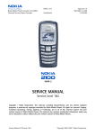
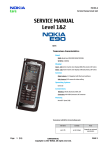
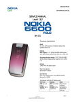
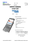
1
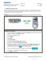
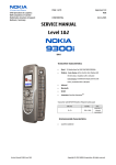
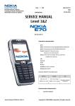
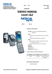
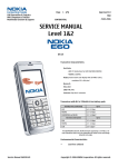
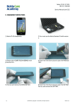
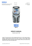
nokia
CONNECTING PEOPLE
PAGE 1 (27)
Nokia Mobile Phones Customer Care EMEA
Technical Services, Repair Concepts
Confidential
nokia
nokia
3650
3660
Approval 4.0
DJk
11.11.2003
NHL-8
Transceiver Features
•
VGA Camera
•
High-resolution, full-color display
•
5-way scroll key
•
Symbian operating system
•
Midi and WAV ringing tones
•
Ringing tone composer
•
Video playback: RealOne player
•
MMC memory card
•
Infrared
•
Bluetooth
•
Support for Java MIDP 1.0
•
Voice dialing
•
Voice recorder
•
Integrated handsfree speaker
•
XHTML browser over GSM data, HSCSD, and
GPRS
•
GSM 900/1800/1900 networks
Transceiver with BL-5C Li-ion 850mAh battery pack
Talk time
4096 colors display
65536 colors display
Up to 2h-4h
Standby
Note
Up to 150h200h
Depends on
network
parameters
SERVICE MANUAL
Service Level 1&2
Copyright © Nokia Corporation. This material, including documentation and any related computer
programs, is protected by copyright controlled by Nokia Mobile Phones. All rights are reserved.
Copying, including reproducing, storing, adapting or translating, any or all of this material requires
the prior written consent of Nokia Mobile Phones. This material also contains confidential
information, which may not be disclosed to others without the prior written consent of Nokia
Mobile Phones.
Service Manual 3650 / 3660 Level 1&2
Copyright 2003 © Nokia Corporation
nokia
CONNECTING PEOPLE
PAGE 2 (27)
Nokia Mobile Phones Customer Care EMEA
Technical Services, Repair Concepts
Confidential
Approval 4.0
DJk
11.11.2003
TABLE OF CONTENT
Page
1.
INTRODUCTION ...................................................................................................................................... 3
2.
GENERAL REPAIR INFORMATION ................................................................................................... 4
3.
PATHFINDER FOR WORKSHOP STAFF............................................................................................ 5
4.
EXPLODED VIEW AND COMPONENT DISPOSAL.......................................................................... 6
5.
SPARE PARTS LIST................................................................................................................................. 7
6.
SERVICE TOOLS.................................................................................................................................... 10
7.
SW UPDATE ............................................................................................................................................ 12
8.
DISASSEMBLY INSTRUCTIONS (ALSO SEE THE VIDEO CLIPS ON CARE POINT) ............ 13
9.
ASSEMBLY OF NEW UI-PWB MODULE AND UI METAL SHIELD............................................ 16
10.
IMPORTANT PRODUCT RELATED SERVICE BULLETINS.................................................... 17
11.
LEGEND FOR QUICK TROUBLE SHOOTER .............................................................................. 17
12.
QUICK TROUBLE SHOOTER PART 1 .......................................................................................... 18
13.
QUICK TROUBLE SHOOTER PART 2 .......................................................................................... 19
14.
QUICK TROUBLE SHOOTER PART 3 .......................................................................................... 20
15.
INFRARED GONOGO TEST ............................................................................................................ 21
16.
CAMERA GONOGO TEST................................................................................................................ 22
17.
BLUETOOTH GONOGO TEST ........................................................................................................ 23
18.
GONOGO TEST .................................................................................................................................. 24
19.
BATTERY TEST.................................................................................................................................. 24
20.
SERVICE NOTES................................................................................................................................ 25
21.
FORWARDING OF REPAIRS TO SERVICE LEVEL 3 OR 4 SUPPLIERS............................... 26
22.
ESD PROTECTION REQUIREMENTS........................................................................................... 27
CHANGE HISTORY
Status
Draft
Approved
Approved
Approved
Approved
Version No.
0.1
1.0
2.0
3.0
4.0
Date
19.09.2003
28.10.2003
03.11.2003
11.11.2003
20.11.2003
Service Manual 3650 / 3660 Level 1&2
Comments
Initial draft
approval
Approval, SPL Update
3660 added
changes in Greek and Russian Keymat
Copyright 2003 © Nokia Corporation
nokia
CONNECTING PEOPLE
PAGE 3 (27)
Nokia Mobile Phones Customer Care EMEA
Technical Services, Repair Concepts
Confidential
Approval 4.0
DJk
11.11.2003
1. INTRODUCTION
The purpose of this document is to help Nokia service levels 1 and 2 workshop technicians to carry out
service to Nokia 3650 and 3660. This Service Manual is to be used only by authorized Nokia service
partners, and the content of it is confidential. Please note that Nokia provides also other guidance
documents (e.g. Service Bulletins) for service partners, follow these regularly and comply with the given
instructions.
While every endeavor has been made to ensure the accuracy of this document, some errors may exist.
If you find any errors or if you have further suggestions, please notify Nokia using the address below:
mailto:[email protected]
Please keep in mind also that this documentation is continuously being updated and modified, so watch
always out for the newest version.
Warnings and Cautions
Please refer to the phone’s user guide for instructions relating to operation, care and maintenance
including important safety information. Note also the following:
Warnings:
1. CARE MUST BE TAKEN ON INSTALLATION IN VEHICLES FITTED WITH ELECTRONIC ENGINE
MANAGEMENT SYSTEMS AND ANTI–SKID BRAKING SYSTEMS. UNDER CERTAIN FAULT CONDITIONS,
EMITTED RF ENERGY CAN AFFECT THEIR OPERATION. IF NECESSARY, CONSULT THE VEHICLE
DEALER/MANUFACTURER TO DETERMINE THE IMMUNITY OF VEHICLE ELECTRONIC SYSTEMS TO RF ENERGY.
2. THE HANDPORTABLE TELEPHONE MUST NOT BE OPERATED IN AREAS LIKELY TO CONTAIN
POTENTIALLY EXPLOSIVE ATMOSPHERES EG PETROL STATIONS (SERVICE STATIONS), BLASTING AREAS ETC.
3. OPERATION OF ANY RADIO TRANSMITTING EQUIPMENT, INCLUDING CELLULAR TELEPHONES, MAY
INTERFERE WITH THE FUNCTIONALITY OF INADEQUATELY PROTECTED MEDICAL DEVICES. CONSULT A
PHYSICIAN OR THE MANUFACTURER OF THE MEDICAL DEVICE IF YOU HAVE ANY QUESTIONS. OTHER
ELECTRONIC EQUIPMENT MAY ALSO BE SUBJECT TO INTERFERENCE.
Cautions:
1. Servicing and alignment must be undertaken by qualified personnel only.
2. Ensure all work is carried out at an anti–static workstation and that an anti–static wrist strap is
worn.
3. Ensure solder, wire, or foreign matter does not enter the telephone as damage may result.
4. Use only approved components as specified in the parts list.
5. Ensure all components, modules screws and insulators are correctly re–fitted after servicing and
alignment. Ensure all cables and wires are repositioned correctly.
6. All PC’s used with NMP Service Software for this produce must be bios and operating system
”Year 2000 Compliant”.
Electrostatic discharge can easily damage the sensitive components of electronic
products. Therefore every Service Supplier has to take care of all precautions, which are
mentioned in the service level related “Service Partner Requirements”, available on
Nokia Partner Web Site. Also see ESD Protection Requirements in this Service Manual.
Service Manual 3650 / 3660 Level 1&2
Copyright 2003 © Nokia Corporation
nokia
CONNECTING PEOPLE
PAGE 4 (27)
Nokia Mobile Phones Customer Care EMEA
Technical Services, Repair Concepts
Confidential
Approval 4.0
DJk
11.11.2003
2. GENERAL REPAIR INFORMATION
IN THIS SECTION THE TECHNICIAN WILL GET SOME GENERAL HINTS HOW TO CARRY OUT REPAIRS:
o
o
o
o
o
o
o
o
o
o
o
o
o
o
To familiarize oneself with Nokia 3650 / 3660 read the tutorials or user guide on
www.nokia.com -->Support--> Phones, by selecting the Phone Model.
Before starting the repair you must take care of ESD precautions like being in your ESD Protected Area
and connecting your wristband.
Use gloves to avoid corrosion and fingerprints.
Protect windows and displays with a film to avoid dust and scratches.
When cleaning the pads you have to use a soft cloth/ESD brush and Isopropanol. It is not allowed to use
a glass fiber pencil because it scratches the surface and will lead later on to corrosion.
Mechanical parts (except shielding lids), which didn’t repair the failure, can be reused, if they are not
soldered.
When removing the shielding lids make sure to replace them with new ones, otherwise the highfrequency leakage can have an influence on the device.
Use always original Nokia spare parts.
Check the soldering joints of the parts which are concerned regarding the indicated error
(e.g. soldered connectors or switches) and resolder them if necessary (Level 2 only).
Remove redundant soldering flux after repair.
Meet the torque requirements when assembling the unit (see also the document “torques for
transceiver assembly” on Nokia Partner Web Site).
Always use your own equipment for testing where you are sure that it works. E.g. if the customer
complains about charger function, please test the phone with your own charger to be sure if phone or
charger causes the malfunction.
When doing the Faultlogger entries, always note the Item code, which caused the malfunction. Also, fill
in the appropriate part code from the assembly, if needed.
Please be aware that some malfunctions could be software related and solved by an update.
These mention Service Bulletins have to be followed:
General
SB-027:
SB-089:
SB-107:
SB-115:
SB-121:
SB-124
SB-131:
SB-148:
SB-156:
SB-161:
SB-163:
SB-164:
SB-165:
SB-167:
Service Tools
SB-011:
Spare Parts
SB-004:
Original Nokia Accessories
Don’t try to repair prototypes (indicated on Type Label).
Be sure that you have minimum hardware requirements in place.
Handling of liquid damages.
Return the defective part, if one of your service tools causes malfunction.
Service Policy for packaging serviced products
Check these guidelines when refurbishing products.
Improvements to Faultlog Reporting Tool
Packing Material
New structure of General Bulletins
Service handling of PWBs and PCBs during repair process
New barcode for future products
NMP Global Symptom Codes
NMP Global Fault Codes (Level 1&2)
NMP Standard Toolkit
New swap phone cartons
Please check Nokia Partner Web Site (PWS) for latest news and files on a regular basis.
Service Manual 3650 / 3660 Level 1&2
Copyright 2003 © Nokia Corporation
nokia
CONNECTING PEOPLE
PAGE 5 (27)
Nokia Mobile Phones Customer Care EMEA
Technical Services, Repair Concepts
Confidential
Approval 4.0
DJk
11.11.2003
3. PATHFINDER FOR WORKSHOP STAFF
In addition to the information in this Service Manual, there are several instructions and information, which
have to be followed.
Main documentation database is Nokia Partner Website, which refers also to Nokia Care Point with the
purpose of serving different multimedia content, like video clips or interactive tutorials.
Nokia Partner Web Site
Nokia Care Point (access through Partner Web Site)
Nokia Partner Web Site for EMEA region is the most important
document database for all service suppliers (level 1-4). All
service relevant information like e.g. Service Manuals, Service
Bulletins or general instructions are available. Content is
restricted according your access level. To be kept up-to-date
also concerning newest software updates, a daily check of
“latest updates in support library” is needed.
Nokia Care Point is repair support and training channel for Nokia
service suppliers (mainly for service levels 1 and 2). By providing
visual and easy to learn support and training material, such as
illustrative repair videos, troubleshooting with pictures, product
information and general repair information, Nokia Care Point
offers user-friendly channel for service partners to learn technical
issues.
It is mandatory to watch for newest technical and organizational information on a daily basis to be
updated as required (see “Latest Updates in support Library”). Every new information has to be processed
and implemented as soon as possible.
When logged into PWS you can also find needed information to different headlines respectively tools
like:
Downloads
Support Library
Accessories
Battery Tester
Common Software
Flashing Tools
General --> Instructions
GoNoGo Tester
Service Tools
Tester Support
Wintesla
Products (Service Manuals, Service Bulletins)
To spare server bandwidth it is recommended to download newest version of huge files like videos,
Phoenix packages or Service Manuals only once and distribute it internally for further use.
Service Manual 3650 / 3660 Level 1&2
Copyright 2003 © Nokia Corporation
nokia
CONNECTING PEOPLE
PAGE 6 (27)
Nokia Mobile Phones Customer Care EMEA
Technical Services, Repair Concepts
Confidential
Approval 4.0
DJk
11.11.2003
4. EXPLODED VIEW AND COMPONENT DISPOSAL
Recommendation for the ecologically friendly disposal of components. Colorized components show the different categories.
Description: See corresponding ITEM/CIRCUIT REF of the SPL (Spare Parts List)
Service Manual 3650 / 3660 Level 1&2
Copyright 2003 © Nokia Corporation
nokia
CONNECTING PEOPLE
PAGE 7 (27)
Nokia Mobile Phones Customer Care EMEA
Technical Services, Repair Concepts
Confidential
Approval 4.0
DJk
11.11.2003
5. SPARE PARTS LIST
MECHANICAL PARTS 3650 / 3660
ITEM/
QTY
CIRCUIT REF.
I001
I002
I003
I004
1
1
6
1
I005
1
I006
1
I007
I008
I009
I010
I011
I012
I013
PART NO
PART NAME
1
1
1
1
1
1
1
XXXXXXX
XXXXXXX
6150091
9480895
9560252
9560302
9481128
9481166
9452603
9458985
9470260
5140251
4858005
9560234
A COVER
KEYMAT
SCREW M1, 6X8,5 TORX T6
SHIELD AND GASKET
UI METAL SHIELD
for Nokia 3650
UI METAL SHIELD
for Nokia 3660
UI PWB MODULE
for Nokia 3650
UI PWB MODULE
for Nokia 3660
PWB INSULATOR
LCD MODULE
EARPIECE GASKET
EARPIECE
CS7 CAMERON SYSTEM MODULE
CAMERA MODULE
CAMERA SHIELD
I014
I015
I016
I017
1
2
1
1
1
9480892
-
ANTENNA MODULE
IHF SPEAKER CONTACT
ACOUSTIC COVER
HANDSFREE SPEAKER
TRI-BAND ANTENNA
I018
I019
I020
I021
I022
I023
I024
I025
I026
1
1
1
1
1
1
1
1
1
9452463
5400287
5140275
5460101
9470264
6800057
9470266
-
POWER KEY
BATTERY CONNECTOR
MICROPHONE MODULE
SM CONN DC JACK+HS/HF SPR
CONNECTOR RETAINER
VIBRA MOTOR
IR WINDOW
B COVER
TYPE LABEL
I027
I028
1
1
1
XXXXXX
-
C COVER MODULE
C COVER
C COVER LATCH
I029
1
9470265
BATTERY FOAM PAD
Service Manual 3650 / 3660 Level 1&2
Copyright 2003 © Nokia Corporation
nokia
CONNECTING PEOPLE
PAGE 8 (27)
Nokia Mobile Phones Customer Care EMEA
Technical Services, Repair Concepts
Confidential
Approval 4.0
DJk
11.11.2003
SOLDERING COMPONENTS ONLY FOR LEVEL 2
ITEM/
QTY
CIRCUIT REF.
F380
G190
S130
1
1
1
PART NO
5119019
4700129
5209001
PART NAME
SM FUSE F 1.5A 32V 0603
BATTERY LITHIUM 0.1MAH 3V
SM SW TACT SPST 12V 50MA SIDE KEY
VARIANT PARTS 3650
ITEM/
QTY
CIRCUIT REF.
I001
I001
I001
I002
1
1
1
1
1
1
1
PART NO
9458717
9458531
9458528
9790661
9458715
9458523
9458521
PART NAME
A COVER BLUE
A COVER YELLOW
A COVER STAY SILVER
KEYMAT LATIN
C COVER BLUE
C COVER YELLOW
C COVER STAY SILVER
VARIANT PARTS 3660
ITEM/
QTY
CIRCUIT REF.
I001
I001
I002
I002
I002
I002
1
1
1
1
1
1
1
1
PART NO
9453606
9453607
9791139
9791140
9791141
9791144
9453605
9453604
Service Manual 3650 / 3660 Level 1&2
PART NAME
A COVER RED
A COVER BLUE
KEYMAT LATIN
KEYMAT RUSSIAN
KEYMAT GREEK
VODAFONE KEYMAT
C COVER RED
C COVER BLUE
Copyright 2003 © Nokia Corporation
nokia
CONNECTING PEOPLE
PAGE 9 (27)
Nokia Mobile Phones Customer Care EMEA
Technical Services, Repair Concepts
Confidential
Approval 4.0
DJk
11.11.2003
SWAP UNITS 3650
QTY
PART NO
0076268
0076629
0076810
0076269
0076270
0076628
0076627
0079356
PART NAME
NHL-8 N3650 SWAP UNIT EUROPE&AFRICA
NHL-8 N3650 SWAP UNIT FRANCE
NHL-8 N3650 SWAP UNIT SOUTH AFRICA
NHL-8 N3650 SWAP UNIT POLAND
NHL-8 N3650 SWAP UNIT TURKEY
NHL-8 N3650 SWAP UNIT CZECH
NHL-8 N3650 SWAP UNIT RUSSIA
NHL-8 N3650 SWAP UNIT UKRAINE
SWAP UNITS 3660
QTY
PART NO
0050892
0050898
0050897
0050893
0050894
0050896
0050895
0050899
PART NAME
NHL-8 N3650 SWAP UNIT EUROPE&AFRICA
NHL-8 N3650 SWAP UNIT FRANCE
NHL-8 N3650 SWAP UNIT SOUTH AFRICA
NHL-8 N3650 SWAP UNIT POLAND
NHL-8 N3650 SWAP UNIT TURKEY
NHL-8 N3650 SWAP UNIT CZECH
NHL-8 N3650 SWAP UNIT RUSSIA
NHL-8 N3650 SWAP UNIT UKRAINE
SERVICE TOOLS
TYPE
ACCESSORY
ACCESSORY
ACCESSORY
ACCESSORY
QTY
PART NO
PART NAME
0080541
0680032
FLS-4S SALES PACK E&A (INCLUSIVE 0680032)
UNIV. POWERSUPPLY ACF-8
0273558
0272169
0272172
0271467
0770582
0730218
0770524
0770526
0772040
0770450
BL-5C BATTERY PACK LI-IO
AC TRAVEL CHARGER ACP-8E (EURO)
AC TRAVEL CHARGER ACP-8X (UK)
HDC-5 HEADSET
FLA-48 POS FLASH ADAPTER
XCS-1 SERVICE CABLE
MJS-93 SOLDERING JIG
SRT-7 CAMERA REMOVAL TOOL
STANDARD TOOLKIT
FLA-48 TESTPINS (10 PCS)
Service Manual 3650 / 3660 Level 1&2
Copyright 2003 © Nokia Corporation
nokia
CONNECTING PEOPLE
PAGE 10 (27)
Approval 4.0
Nokia Mobile Phones Customer Care EMEA
Technical Services, Repair Concepts
Confidential
DJk
11.11.2003
6. SERVICE TOOLS
ACF-8
Universal Power Supply is used to power FLS-4S.
FLS-4S incl. Driver and User Guide
is a dongle and flash device incorporated into one package,
developed specifically for POS use.
XCS-1
Service Cable is used to connect FLS-4S to FLA-48.
Internal Battery BL-5C
Inserted under the back cover, this Li-ion battery provides
power in a lightweight package.
Travel Charger ACP-8E/ACP-8X
Lightweight multi-voltage charger for charging your phone
battery.
Headset HDC-5
An easy and convenient handsfree solution with remote
control.
FLA-48
POS Flash Adapter is used in POS (Point of Sales)
environment for software updating. It provides controlled
supply voltage and necessary connections between the
phone and the Flash Device. It substitutes for the phone’s
standard battery during the software update.
SRT-7
Camera removal tool.
Service Manual 3650 / 3660 Level 1&2
Copyright 2003 © Nokia Corporation
nokia
CONNECTING PEOPLE
PAGE 11 (27)
Approval 4.0
Nokia Mobile Phones Customer Care EMEA
Technical Services, Repair Concepts
Confidential
DJk
11.11.2003
MJS-93
Soldering Jig (for Level 2 or higher service level supplier)
Test Pins
for POS Flash Adapter FLA-48
NMP code 0772040
Content
Nokia opening tool SRT-6 Nokia No. 0770431
Tonichi torque driver Nokia No. 6901525
Hoya micro fibre cloth MX304
Dastex gloves S, M, XL
Artilux goggles AH166
Wera bit T5 867/4TX 5x50
Wera bit T6 867/4TX 6x50
Wera bit T6 PLUS® 867/4TX 6IP
Facom side cutter 416E
Facom T5 driver SP.14032
Facom T6 driver SP.14033
Facom slot screwdriver AEF. 2x35.E
Wetec tweezers 7abb SA-ESD
Wetec tweezers 22 SA-ESD
Wetec tweezers 13 SA-SMD ESD
Wetec tweezers PSF SA-ESD
Wetec ESD brush E1211
Kaiser Fototechnik airbrush 6315
Wetec dental tool DEM83266/0
RS Components Scissors 323-5732
Service Manual 3650 / 3660 Level 1&2
Copyright 2003 © Nokia Corporation
nokia
CONNECTING PEOPLE
PAGE 12 (27)
Approval 4.0
Nokia Mobile Phones Customer Care EMEA
Technical Services, Repair Concepts
Confidential
DJk
11.11.2003
7. SW UPDATE
To use FLS-4S Flash Dongle you have to follow the user guide inside the sales package. Please
check always the latest version of flash software, which is available on Partner Web Site.
Flash Concept – (Point of Sales)
It is very important to follow this insertion
and removal procedure, otherwise the
contact pins of Flash Adapter will be
damaged.
Note: software for 3660 (64k color) devices
will not run on 3650 devices !
Standard installation for software update.
Insert the Flash Adapter FLA-48 like a battery,
start at the battery connector site.
Now, push down the bottom side of the phone,
do not use too much force.
When removing the Flash Adapter, always start
from the bottom side of the unit.
Take away the unit now.
Service Manual 3650 / 3660 Level 1&2
Copyright 2003 © Nokia Corporation
nokia
CONNECTING PEOPLE
PAGE 13 (27)
Approval 4.0
Nokia Mobile Phones Customer Care EMEA
Technical Services, Repair Concepts
Confidential
DJk
11.11.2003
8. DISASSEMBLY INSTRUCTIONS (ALSO SEE THE VIDEO CLIPS ON CARE POINT)
Press the Release Button before removing ACover.
The A-Cover is attached with hooks at both sides.
To remove it, press B-Cover carefully as shown in
the picture.
Press the latch before removing C-Cover.
Always protect Camera Window with protection
foil to avoid dust and scratches.
Unscrew the TORX PLUS® screws size 6, using the
order shown. For assembly, take reverse order
and torque of 15Ncm. Use always new screws
for assembly.
Take the modules from B-Cover.
Use SRT-6 to open the Connector carefully.
Separate the UI Module from Radio Module.
Service Manual 3650 / 3660 Level 1&2
Copyright 2003 © Nokia Corporation
nokia
CONNECTING PEOPLE
PAGE 14 (27)
Approval 4.0
Nokia Mobile Phones Customer Care EMEA
Technical Services, Repair Concepts
Confidential
DJk
11.11.2003
Open the shield snaps on both sides with SRT-6.
Remove the Shield and Gasket.
Always protect LCD with protection foil to avoid
dust and scratches.
Open the UI Metal Shield snaps with SRT-6.
Remove UI Metal Shield.
Remove UI PWB Module.
The speaker is attached with double-sided
adhesive Gasket. To remove it, push it with Torx
driver carefully.
Antenna drops out when turning B-Cover.
Service Manual 3650 / 3660 Level 1&2
Copyright 2003 © Nokia Corporation
nokia
CONNECTING PEOPLE
PAGE 15 (27)
Approval 4.0
Nokia Mobile Phones Customer Care EMEA
Technical Services, Repair Concepts
Confidential
DJk
11.11.2003
Remove IR Window as shown in the picture.
Remove the Vibra Motor from its guidance.
Move SRT-7 through this gap of B-Cover to remove
Connector Retainer.
Turn B-Cover let System Connector with Connector
Retainer drop out.
Use tweezers to pull up Microphone.
To remove the Battery Connector, use SRT-6
Opening Tool.
Remove Power Key.
Service Manual 3650 / 3660 Level 1&2
Copyright 2003 © Nokia Corporation
nokia
CONNECTING PEOPLE
PAGE 16 (27)
Approval 4.0
Nokia Mobile Phones Customer Care EMEA
Technical Services, Repair Concepts
Confidential
DJk
11.11.2003
Remove Camera Shield if you need to clean
contacts or change Camera Module.
Camera Module is attached with four snaps onto
Camera Connector. Place the SRT-7 as shown in
the picture and carefully move the snaps to the
right.
The Camera Module comes up automatically
when snaps are released.
Remove the Camera Module carefully. Note the
guiding pin when doing assembly.
9. ASSEMBLY OF NEW UI-PWB MODULE AND UI METAL SHIELD
Place UI-PWB Module between LCD Module and
Shield & Gasket.
Mount UI Metal Shield.
Bend UI Metal Shield latch on backside.
Attach the PWB Insulator and take care of the
markings.
Copyright 2003 © Nokia Corporation
Service Manual 3650 / 3660 Level 1&2
nokia
CONNECTING PEOPLE
PAGE 17 (27)
Approval 4.0
Nokia Mobile Phones Customer Care EMEA
Technical Services, Repair Concepts
Confidential
DJk
11.11.2003
10. IMPORTANT PRODUCT RELATED SERVICE BULLETINS
SB-012: CORRUPTED PERMANENT MEMORY MANAGER (PMM)
11. LEGEND FOR QUICK TROUBLE SHOOTER
This legend is valid for all parts of the Quick Trouble Shooter
Follow the steps until the problem is solved. If this doesn’t help, you are not authorized to go forward.
Only underlined components ( e.g. I002) can be changed.
The start point of repair activities regarding the appeared fault symptoms.
Follow the arrows step by step
Pads or contacts: Check optical and mechanical condition particularly
regarding to corrosion. Clean if necessary.
Measure component for electrical functionality and change, if needed.
(Level 2 only)
Pads or contacts: Check optical and mechanical condition particularly
regarding to corrosion. Clean with ESD brush only, if necessary.
No more actions possible send product to the appropriate service partner
with higher service level.
Service Manual 3650 / 3660 Level 1&2
Copyright 2003 © Nokia Corporation
nokia
CONNECTING PEOPLE
PAGE 18 (27)
Approval 4.0
Nokia Mobile Phones Customer Care EMEA
Technical Services, Repair Concepts
Confidential
DJk
11.11.2003
12. QUICK TROUBLE SHOOTER PART 1
Service Manual 3650 / 3660 Level 1&2
Copyright 2003 © Nokia Corporation
nokia
CONNECTING PEOPLE
PAGE 19 (27)
Approval 4.0
Nokia Mobile Phones Customer Care EMEA
Technical Services, Repair Concepts
Confidential
DJk
11.11.2003
13. QUICK TROUBLE SHOOTER PART 2
Service Manual 3650 / 3660 Level 1&2
Copyright 2003 © Nokia Corporation
nokia
CONNECTING PEOPLE
PAGE 20 (27)
Approval 4.0
Nokia Mobile Phones Customer Care EMEA
Technical Services, Repair Concepts
Confidential
DJk
11.11.2003
14. QUICK TROUBLE SHOOTER PART 3
Service Manual 3650 / 3660 Level 1&2
Copyright 2003 © Nokia Corporation
nokia
CONNECTING PEOPLE
PAGE 21 (27)
Approval 4.0
Nokia Mobile Phones Customer Care EMEA
Technical Services, Repair Concepts
Confidential
DJk
11.11.2003
15. INFRARED GONOGO TEST
You need another infrared device (e.g. 6310i) to do a GoNoGo test. The infrared windows of the
devices must be directed to each other and should have a distance of approximate 15 cm. Make
sure that infrared is activated in receiver device.
Warning: Do not point the IR (infrared) beam at anyone’s eye or allow it to interfere with other
IR devices. This device is a Class 1 Laser product.
Reference unit
Test unit
Settings on the test unit:
o
From Home Menu, select
key. This displays Contacts entries. If phone and SIM
memory is empty, create one new entry.
o
Choose one phonebook entry.
o
Select Options
o
Select Send
o
Select Via infrared
o
Press OK for Selected detail only (optional).
o
You get this message Connecting via infrared.
o
If sending of business card fails and you get message Unable to connect, make
sure again, that infrared windows are directed to each other and infrared is
activated in reference device
. Then try again sending.
o
Test is successful, if you get this message on receiver device
o
You will get a confirmation on sender device, too.
o Press
.
for Home Menu.
Service Manual 3650 / 3660 Level 1&2
Copyright 2003 © Nokia Corporation
nokia
CONNECTING PEOPLE
PAGE 22 (27)
Approval 4.0
Nokia Mobile Phones Customer Care EMEA
Technical Services, Repair Concepts
Confidential
DJk
11.11.2003
16. CAMERA GONOGO TEST
Before starting the GoNoGo
test, check that camera
window in B-Cover is clean.
If not, clean the window
with cloth.
If camera lens is dirty, do
not use cloth or brush for
cleaning, use compressed
air only.
Exchange
of
Camera
Module will not improve
picture quality!
o
From Home Menu, select Camera.
o
To take a picture, press
o
This image will be saved automatically.
o
Test is successful, if the image appears on your display. The camera is ok.
o
Select Options
o
o
Select Delete
o
button.
Select YES
Press
for Home Menu.
o If test fails, see Quick Trouble Shooter.
Service Manual 3650 / 3660 Level 1&2
Copyright 2003 © Nokia Corporation
nokia
CONNECTING PEOPLE
PAGE 23 (27)
Approval 4.0
Nokia Mobile Phones Customer Care EMEA
Technical Services, Repair Concepts
Confidential
DJk
11.11.2003
17. BLUETOOTH GONOGO TEST
You need another Bluetooth device (e.g. 6310i) to do a GoNoGo test.
Make sure that Bluetooth is activated in the reference unit. The distance of the devices
should be not more than 5m from each other.
Test unit
Reference unit, Bluetooth activated
Setting on the test unit:
o
From Home Menu, push the Menu key
o
Select Games
o
Select Snake EX
o
Select Option
o
Select Play 2-player
o
Select Via Bluetooth
o
Select Client
o
Select Yes, if Bluetooth is not already activated, otherwise go to next step.
o
Search window appears, if all Bluetooth devices in range will be displayed, the
.
test is successful!
o Press
for Home Menu.
Service Manual 3650 / 3660 Level 1&2
Copyright 2003 © Nokia Corporation
nokia
CONNECTING PEOPLE
PAGE 24 (27)
Approval 4.0
Nokia Mobile Phones Customer Care EMEA
Technical Services, Repair Concepts
Confidential
DJk
11.11.2003
18. GONOGO TEST
After the optical check a GoNoGo test has to be carried out if the unit has been unscrewed to
guarantee the functionality of the phone.
Please refer to the actual information on Partner Web Site and Nokia Care Point. When using
delivered tester support files, take care of the right setup according to the tester type and product
type.
Please refer to “Recommended Service Equipment” on Nokia Partner Web Site.
Mobile Phone Tester
19. BATTERY TEST
A battery tester lets you test the capacity of Nokia batteries.
Please refer to the actual information on Partner Web Site.
http://www.astratec.co.uk/
Service Manual 3650 / 3660 Level 1&2
http://www.cadex.com/
Copyright 2003 © Nokia Corporation
nokia
CONNECTING PEOPLE
PAGE 25 (27)
Approval 4.0
Nokia Mobile Phones Customer Care EMEA
Technical Services, Repair Concepts
Confidential
DJk
11.11.2003
20. SERVICE NOTES
We recommend using Service Notes when shipping phones to other Service Partners. It prevents the
product from scratches, it is ESD-neutral and has the possibility to give valuable feedback of the fault
symptom through a structured form. Please refer to the document Service Notes for faulty NMP
transceiver on Partner Web Site to get further information.
Service Manual 3650 / 3660 Level 1&2
Copyright 2003 © Nokia Corporation
nokia
CONNECTING PEOPLE
PAGE 26 (27)
Approval 4.0
Nokia Mobile Phones Customer Care EMEA
Technical Services, Repair Concepts
Confidential
DJk
11.11.2003
21. FORWARDING OF REPAIRS TO SERVICE LEVEL 3 OR 4 SUPPLIERS
We recommend using the offered swap phone cartons as described in Spare Parts SB-004.
Always Protect the window with a protection film.
Put the unit under the stretch film.
Add repair documentation e.g. filled-in service note
into the swap carton.
Fold the swap carton as shown in Spare Parts SB-004.
There are two different sizes of swap cartons for common mobile phones.
Service Manual 3650 / 3660 Level 1&2
Copyright 2003 © Nokia Corporation
nokia
CONNECTING PEOPLE
PAGE 27 (27)
Approval 4.0
Nokia Mobile Phones Customer Care EMEA
Technical Services, Repair Concepts
Confidential
DJk
11.11.2003
22. ESD PROTECTION REQUIREMENTS
Please refer to the Partner Web Site document
Service Partner Requirements in folder General instructions.
USE Conductive bags and boxes
USE ESD compatible service tools
USE Conductive wastebaskets
USE ESD gloves when handling PWBs/PCBs
USE Cleaning material without changing el. Characteristics
USE Grounded service equipment, i.e. soldering station
USE ESD clothes such as coat or frock
NO Smoking
NO Drinking
NO Eating
NO Dust
NO Useless Items
NO Normal pressured air for
cleaning modules/displays
The video covers general issues concerning Electro-Static Discharge (ESD)
source: Nokia Care Point
Service Manual 3650 / 3660 Level 1&2
Copyright 2003 © Nokia Corporation