1
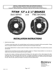
TITAN
10” X 2 ¼” BRAKES
FREE BACKING* UNI-SERVO
u.s. PATENT 4,787,487
PREMIER & STANDARD
Limited Warranty TITAN Inc. ("TITAN') warrants its products to be free from defects in material and workmanship for
one year from date of delivery to the original purchaser when properly installed, used and maintained by the
purchaser.
TITAN LIMITED WARRANTY
TITAN warrants its complete braking systems (TITAN PREMIER, MARINE & STANDARD brakes, TITAN
TITAN EXTENDS NO WARRANTY, EXPRESS OR IMPLIED, ON PRODUCTS NOT
MANUFACTURED BY TITAN OR TO TITAN'S DESIGN SPECIFICATION, INCLUDING BUT NOT
LIMITED TO SUCH ITEMS AS NON-TITAN TIRES, BEARINGS, HOSE AND TUBING.
PURCHASER'S RECOURSE SHALL BE LIMITED TO ANY WARRANTY OF THE RESPECTIVE
MANUFACTURERS.
hubs/drums, and TITAN actuators) to be free from defects in material and workmanship for two years when properly
THIS WARRANTY EXCLUDES ALL IMPLIED WARRANTIES OF MERCHANTABILITY OR
FITNESS FOR A PARTICULAR PURPOSE OR ANY PURPOSE.
installed, used and maintained.
TITAN warrants that the PREMIER BRAKE will be free from a corrosion-related failure of brake components for two
years when properly installed, used and maintained.
This warranty does not apply to damage or loss caused by any or all of the following circumstances or conditions:
Freight damage.
Parts, accessories, materials or components not obtained from or approved in writing by TITAN. Misapplication,
misuse and failure to follow the directions or observe cautions and warnings on installation, operation, application,
inspection or maintenance specified in any TITAN quotation, acknowledgement, sales literature, specification sheet
or installation instruction and service manual ("applicable literature').
If any TITAN products are found upon TITAN's examination to have been defective when supplied, TITAN will either:
credit the purchaser's account for the purchase price of the TITAN product; replace the TITAN product; or repair the
product. TITAN has sole discretion in choosing which option to provide. For this LIMITED WARRANTY to apply,
TITAN must receive notice of the alleged defect within 30 days of either the discovery of the alleged defect or the
expiration of the warranty period, whichever is earlier. Any claim not made within this period shall conclusively be
deemed waived.
If requested by TITAN, purchaser shall return the alleged defective product to TITAN for examination at TITAN's
direction and expense. TITAN will not pay for expenses incurred in returning a product to TITAN without TITAN's
prior written authority. TITAN shall not be liable for any other expenses purchaser incurs to remedy any defect.
Purchasers waive subrogation on all claims under any insurance.
Limitation of Liability It is expressly agreed that the liability of TITAN is limited and TITAN does not function as an
insurer. THE REMEDIES SET FORTH IN THIS WARRANTY SHALL CONSTITUTE THE EXCLUSIVE REMEDIES
AVAILABLE TO THE PURCHASER OR USER AND ARE IN LIEU OF ALL OTHER REMEDIES, EXPRESS OR
IMPLIED. THE LIABILITY OF TITAN, WHETHER IN CONTRACT, IN TORT, UNDER ANY WARRANTY OR
OTHERWISE,
SHALL
NOT
EXCEED
THE
PURCHASE
PRICE
OF
THE
PARTICULAR
PRODUCT
MANUFACTURED, SOLD OR SUPPLIED BY TITAN.
To Obtain Technical Assistance To enable TITAN to respond to a request for assistance or evaluation of customer or
user operating difficulty, please provide at a minimum the following information by calling 1-800-247-1781 or within
Iowa 1-515-244-7286:
Model number_ serial number and all other data on the specific component which appears to be
involved in .the difficulty. The date and from whom you purchased your TITAN product.
State your difficulty, being sure to mention at least the following: Application, Nature of load involved,
and Weight of the load.
Field Service If field service at the request of the purchaser is rendered and the difficulty is found not to be with
TITAN's product, the purchaser shall pay the time and expense (at the prevailing rate at the time of service) of
seller's field representative(s). Charges for service, labor and other expenses that have been incurred by the
purchaser, its customer or agent without prior written authorization of TITAN will not be accepted.
Page 1 of 8
THIS WARRANTY DOES NOT COVER NOR EXTEND TO INCIDENTAL OR CONSEQUENTIAL
DAMAGE. Some states do not allow the exclusion or limitation of incidental or consequential damages,
so the above limitation or exclusion may not apply to you. This warranty gives you specific legal rights,
and you may also have other rights which vary from state to state.
No representative has authority to make any representation, promise or agreement except as stated in
this Limited Warranty, TITAN reserves the right to make design and other changes upon its products
without any obligation to install the same on any previously sold or delivered products.
THERE ARE NO WARRANTIES WHICH EXTEND BEYOND THOSE DESCRIBED ABOVE.
EFFECTIVE JULY 1, 1991 THIS WARRANTY SUPERSEDES ALL PRIOR WARRANTIES, WRITTEN
OR IMPLIED.
DUE TO THE WIDE VARIATION IN USES TO WHICH TITAN PRODUCTS (WHE£LS, HUBS,
BRAKES, ETC.) ARE SUBJECTED BY USERS, WE ARE UNABLE TO SPECIFY CARRYING
CAPACITIES OR SPEEDS FOR A PARTICULAR APPLICATION. THEREFORE, THE
MANUFACTURER MUST TEST HIS EQUIPMENT UNDER THE MOST SEVERE CONDITIONS TO
DETERMINE THAT TITAN PRODUCTS ARE SUITABLE
PNEUMATIC TIRE WARNING
Danger-Only specially trained persons using proper equipment shall mount or demount pneumatic
tires. Serious or fatal injuries can result from using improper mounting procedures.
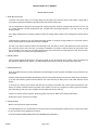
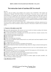
INSTRUCTIONS FOR 10" BRAKES
BRAKE INSTALLATION
1. Brake Mounting Flange
To assure correct brake action, the mounting flange must be square and concentric with the axle spindle. A flange that is
not properly installed will contribute to rapid lining wear and improper brake action.
The 10" TITAN brake is designed to interchange with existing equipment mounting on flanges with (4) holes on 4" B.C. and
a 3" register diameter. Several manufacturers offer complete axles with flanges attached, or you may choose to install
flanges yourself.
Use a flange welding fixture to properly position the flange for welding. Bolt the flange to the welding fixture securely with all
bolts.
Install the fixture (and flange) onto the spindle and tighten spindle nut. If flange is being installed on a round axle, rotate to
secure "wheel cylinder up" location when the axle is installed.
It is best not to make a continuous weld around the flange. First, tack weld on all four sides between the bolts. Follow this
with a full weld up each side of the axle. It is usually not advisable or necessary to weld across the top and bottom of the
axle. The bottom of the axle is its most highly stressed area and a weld at this point will weaken the axle. Allow the axle,
spindle, and flange to cool before removing welding fixture.
2. Installing Brakes
Place the brake against spindle flange. In mounting the brake, be sure the hydraulic wheel cylinder is at the top. Brakes are
also marked as "RIGHTS" and "LEFTS". The brake designated as "LEFT" travels on the driver's side of the road.
3. Installing Brake Drum
When the brakes have been correctly assembled to the axle flanges, the hub and drum assemblies may be mounted on the
axle spindle.
Pack the inside bearing with suitable wheel bearing grease. Force grease through and around the rollers. Place the bearing
in the hub and install the grease seal flush with the end of the hub using an arbor press or soft mallet. Remove excess
grease.
To avoid injury to bearing seal, lubricate seal seat prior to putting on the brake drum. Grease pack and install the outer
bearing on spindle. Place flat washer and spindle nut on spindle. Turn drum as you tighten nut. When a pronounced drag is
felt in the bearings, back off nut one complete slot and install cotter pin and dust cap.
Caution: Do not pack hub full of grease. Excessive grease may leak into brake drums causing brake failure.
Wheels may now be mounted on the trailers.
4. Adjusting Brakes
Before removing the jacks, adjust the brakes.
The brake adjustment nut is located behind a slot at the bottom of the backing plate. Tighten until you cannot rotate wheel
by hand, then back off the adjustment 10 notches.
ALWAYS ROTATE DRUM IN DIRECTION OF FORWARD ROTATION ONLY.
#24037
Page 2 of 8
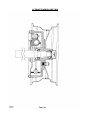
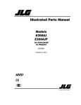
10" BRAKE Installation
5. Hydraulic Lines
Use care in forming tubing to avoid sharp bends or kinks. Double flare steel tubing to assure tight leak proof connections.
Anchor all hydraulic lines at two foot intervals to prevent chafing and vibration. Use hydraulic rubber hose at points of
flexing. Anchor hose ends to avoid stress on tubing.
6. Bleeding the System
The first requisite for safe, sure hydraulic braking is the use of quality brake fluid. Use only DOT-3 or DOT-4 heavy duty
fluid.
If pressure bleeding equipment is available, follow the manufacturer's instruction in bleeding the system.
If system must be bled manually, proceed as follows: Fill master cylinder with fluid. Install bleeder hose on first wheel
cylinder to be bled, (if tandem axle trailer, bleed rear axle first). Have loose end of hose submerged in brake fluid in glass
container to observe bubbling.
By loosening the bleeder screw located in the wheel cylinder one turn, the system is open to the atmosphere through the
passage drilled in the screw. Pump actuator with long steady strokes. The bleeding operation is completed when bubbles
no longer rise to the surface of the fluid. Be sure to close bleeder screw securely.
Repeat bleeding operation at each wheel cylinder. During the bleeding process, replenish the brake fluid, so the level does
not fall below the 1/2 full level in the master cylinder reservoir. After bleeding is completed, make sure master cylinder is
filled to 3/8 inch below the top of the reservoir, and filler cap 'securely in place.
WARNING
Saltwater, granular fertilizers and other corrosive materials are destructive to metal. To prolong the life of a braking system
used under corrosive conditions, we recommend that the Actuator be flushed after use with a high pressure water hose. Be
sure to re-grease bearings and oil all moving parts after the unit has dried. At the end of the season, when unit is to be
stored, remove the brake drums and clean inside the brakes. Pack wheel bearings before drum is installed. Failure to
properly and adequately grease and maintain the actuator could weaken it and/or cause it to fail and result in serious injury
and/or property damage.
#24037
Page 3 of 8
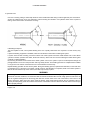
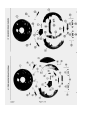
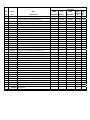
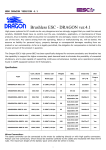
10” BRAKE DIAGRAM, SIDE VIEW
.
BRAKE TYPE
REF.
PART
PART
PREMIER
FREE
PREMIER
UNI-
NO.
NO.
DESCRIPTION
BACKING
SERVO
4423400
4445300
4522800
FREE
UNIBACKIN SER
G
VO
4071500 1878700
Complete Brake w/o Parking Brake-Left
4423500
4445400
4522900
4071600 1878800
Complete Brake w/ Parking Brake-Right
Complete Brake w/ Parking Brake-Left
Back Plate Assembly-Black
4423600
4423700
0
-
Complete Brake w/o Parking Brake-Right
0
-
Q
0
1
2463600042
1
2463650
1
2463600410
2
2
1791000
1095200
Front Shoe Assembly
Front Shoe Assembly
2
4437100
Front Shoe Assembly
2
3
3
4445900
1095300
4437200
Front Shoe Assembly
Rear Shoe Assembly
Rear Shoe Assembly
4
0977600
Wheel Cylinder Assembly-Right, Greased and Painted
5
6
0977700
0977800
Wheel Cylinder Assembly-Left, Greased and Painted
Cap Screw & Lockwasher, 5/16-18NC X 112
6
4439700
Cap Screw & Lockwasher, 5/16-18NC X 112
7
0978300
Push Rod
7
8
4437700
4437500
Push Rod
Adjusting Screw Assembly
9
1095700
Spring-Adjusting Screw
9
10
10
4438400
4720800183
4720800317
Spring-Adjusting Screw
Shoe Lever-Clear Zinc
Shoe Lever-E-Coat
11
1791700183
Travel Link-Clear Zinc
11
12
13
1791700184
1740600
0794900
Travel Link-Olive Drab
Hex Locknut, 5/16 - 18 NC (2 Way)
Hex Cap Screw, 5/16 - 18NC X 5/8
1
1
Hex Cap Screw, 5/16 - 18NC X 5/8
1
13
4424700
14
14
15
16
16
17
17
125600183
1256000184
0777801184
1095800
4438500
0978500
4438600
GALVANIZED
N/A
N/A
1
Back Plate Assembly-Galvanized
Back Plate Assembly-Premier
Pin-Front Shoe, wlo Parking Brake-Clear Zinc
Pin-Front Shoe, wlo Parking Brake-Olive Drab
Retaining Ring-Yellow Dichromate Plating
Spring-Shoe Return
Spring-Stainless Steel Shoe Return
Spring-Lever
Spring-Lever Stainless Steel
FREE
BACKING
1
1
1
1
1
1
1
1
1
1
1
1
1
1
1
2
1
2
1
2
1
1
1
1
1
1
2
2
1
1
1
1
1
1
1
1
1
1
1
1
1
1
1
1
1
1
1
1
1
1
1
2
1
1
2
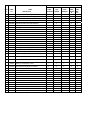
PART
PREMIER
FREE
BRAKE TYPE
PREMIER GALVANIZED
UNIFREE
REF.
PART
NO.
NO.
18
0681400
Spring-Lower Free Backing Shoe
18
4438700
Spring-S.S. Lower Free Backing Shoe
19
1095900
Pin-Shoe Hold Down, #8, Stainless Steel
1
20
0978800
Pin-Shoe Hold Down, #1, Stainless Steel
1
21
0978900
Cup-Shoe Hold Down, Stainless Steel
4
4
22
22
1096000
4438800
Spring-Shoe Hold Down
Spring-Shoe Hold Down, Stainless Steel
2
2
23
2475700
Cover-Adjusting Hole, Plastic
2
2
1
DESCRIPTION
BACKING
SERVO
BACKING
FREE
BACKIN
G
1
2
1
1
1
1
UNISER
VO
2
1
4
4
4
2
2
2
24
4437600
Socket-Adjusting Screw
25
26
4446000
1895000
Shoe Guide
Washer, Shoe Guide, 17/32IDX1-3/160DX10 GA
26
4439500
Washer, Shoe Guide, 17/32IDX1-3/160DX10 GA
33
1050800
Hex Cap Screw, 1/4 - 20NC X 3/4
33
34
4424900
4070700
Hex Cap Screw, 1/4 - 20NC X 3/4
Hex Locknut, 1/4 - 20NC (2 Way)
1
*37
4439200
Parking Lever Assembly-Right
1
1
*37
*38
*-
4439300
0979500
4364800
Parking Lever Assembly-Left
Retainer
1
1
1
1
Toggle Link Assy.-R
1
**
4364900
Toggle Link Assy.-L
1
4440000
Hex Nut, 7/16
- 20NF
4
4439600
Lockwasher, 7/16 Std.
4
1584500
Wheel Cyl. Kit-Wagner FC 13620
1
1
1
1
1
4744600
Dust Plug-Parking Brake, Not Shown
2
2
2
2
2
-
4745900
4743300
Flush Kit Plug, Not Shown
Mounting Bolt 7/16-20NF
1
4
1
1
1
*
*14
4438300
Anchor Pin, Parking Brake
1
-
4424800
Locknut 5/16, Not Shown
1
1
-
4439800
Locknut 1/4, Not Shown
1
1
-
4748800
4748403
Premier Brake Shoe Kit 10 x 2 1/4 F.B.
L.H. Premier Free Backing Shoe Assembly
1
1
1
1
-
4748404
R.H. Premier Free Backing Shoe Assembly
1
1
-
4742700
4043100
4748401
4748402
Premier Brake Shoe Kit - Uni-Servo
Brake Shoe Kit - Uni-Servo
L.H. Free Backing Shoe Assembly
RH. Free Backing Shoe Assembly
*
*
-
*Used on models with parking brakes linkages.
1
1
1
1
1
1
1
1
1
1
1
1
.
1
1
1
1