1
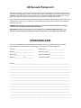
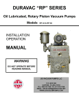
LRH SERIES
TWO STAGE
LIQUID RING VACUUM PUMPS
Models
LRH 45,75,100,140,200,250,300,400,500,850
INSTALLATION
OPERATION
MAINTENANCE
MANUAL
WARNING
DO NOT OPERATE BEFORE
READING MANUAL
US VACUUM PUMPS LLC
P.O. BOX 909
CANTON, TX USA 75103
TEL: 888-416-7366 FX: 877-416-7599
EMAIL: [email protected]
WWW.USVACUUMPUMPS.COM
FORWARD
This manual contains installation, operation, maintenance and troubleshooting information for the Model
LRH-45, LRH-75, LRH-100, LRH-140, LRH-200, LRH-250, LRH-300, LRH-400, LRH-500, LRH-850 Liquid
Ring Vacuum Pumps. Please read it in its entirety before operating the pump.
Our Liquid Ring Vacuum Pumps are designed to ensure safety when used properly. It is the responsibility of the
user to follow safety-related warnings, cautions, notes and other requirements described in this manual.
Returned equipment will not be accepted by our company without prior authorization. Prior to shipping please
call for a returned goods authorization number (RGA).
Our company reserves the right to cancel the warranty if the pump is disassembled without authorization, if
pump fluids are used that are not compatible with the design and materials used in the manufacturer of the
pump, and if unauthorized spare parts are used.
2
SAFETY INSTRUCTIONS FOR LIQUID RING
VACUUM PUMPS
Please read the following safety information on this page before operating your
vacuum pump
•
Do not operate the pump without the belt guard or coupling guard properly
attached. Disconnect the pump from the electrical supply at the main before
removing the guard. Replace the guard before reconnecting the power supply.
Operating the pump without the guard secured in place exposes people in the
vicinity of the pump to risk from rotating drive parts. Make sure the pump is
completely reassembled, the belt guard is replaced, and all drain and fill valve
and plugs are closed before reconnecting the power supply.
•
Do not operate the pump with oxygen enriched gas in the suction line, where the
proportion of oxygen exceeds 20%, unless the pump is using water as a sealant or
an inert fluid suitable for the application. Pumping oxygen enriched gases with
mineral oil or other non-inert fluids can cause an explosion in the pump, resulting
in damage or injury.
•
Take precaution to avoid prolonged or excessive exposure to oil mist or process
materials from the discharge of the pump, or, prolonged or excessive exposure to
oil mist from oil sealed pumps. Do not allow the pump to discharge into closed
room, or a room without adequate ventilation. Always use a discharge oil mist
eliminator for oil sealed systems. Venting the outlet of the pump or oil mist
eliminator to the open air is highly recommended.
•
Do not restrict the pump discharge line in any way, or place any valves in the
discharge line. The vacuum pump is a compressor and will generate high
pressures without the motor stalling when at low suction pressures. Excessive
pressure build-up could cause damage or injury.
•
Accidental starting or operation of the pump while maintenance is in progress may
cause injury or damage
•
Lift only with the frame mounted eyebolts.
3
WARNING
•
THE BELTGUARD OR COUPLING GUARD MUST BE PROPERLY SECURED
IN PLACE AT ALL TIMES WHILE THE PUMP IS RUNNING
CAUTION
•
•
•
•
•
•
DO NOT OPERATE THE PUMP DRY
MAKE SURE COOLING LIQUID IS AVAILABLE TO THE PUMP & SEALS
DO NOT ALLOW SEALANT LIQUID TO FREEZE IN THE PUMP
DISCHARGE PIPING SHOULD NOT EXCEED 24 INCHES ABOVE
THE DISCHARGE FLANGE
SUCTION MANIFOLD MUST BE FREE OF WELDING SLAG
DO NOT START THE PUMP WITH SEALANT LEVEL ABOVE SHAFT CENTERLINE
4
TABLE OF CONTENTS
1. Safety Instructions……………………………………………Page 2
2. General………………………………………………………... Page 6
3. Introduction…………………………………………………….Page 7
4. Specifications…………………………………………………. Page 8
5. System Components………………………………………….Page 9
6. Principle of Operation………………………………………... Page 10
7. Seal Water Arrangements…………………………………... Page 11
8. Properties of sealants……………………………………….. Page 12
9. Type of Sealant systems……………………………………. Page 13
10. Operation….……….………………………………………… Page 14
11. Disassembly & Reassembly………………………..………. Page 17
12.Trouble shooting Chart……..……………………………….. Page 19
13. Sectional Drawings & Parts List……………………………. Page 1
****************************
5
US Vacuum Pumps LLC
CONGRATULATIONS on your purchase of a new Liquid ring Vacuum Pump from US VACUUM. Please examine
the pump for shipping damage, and if any damage is found, report it immediately to the carrier. If the pump is to be
installed at a later date make sure it is stored in a Clean, dry location and rotated regularly. Make sure covers are
kept on all openings. If pump is stored outdoors be sure to protect it from weather and corrosion.
LRS vacuum pumps are built to exacting standards and if properly installed and maintained will provide many years
of reliable service. We urge you to take time to read and follow every step of these instructions when installing &
maintaining your pump.
WARNING: Serious injury can result from operating or repairing this machine without first reading the
service manual and taking adequate safety precautions.
IMPORTANT: Record the pump model and serial number in the OPERATING DATA form below. You
will save time and expense by including this reference information on any replacement parts orders.
OPERATING DATA
It is to the user’s advantage to have the requested data filled in below and available in the event a problem
should develop in the vacuum pump. This information is also helpful when ordering spare parts.
Model No____________________________
Sealing Fluid_____________________________
Serial No.____________________________
Operating Vacuum________________________
Startup Date__________________________
Inlet Gas Composition_____________________
Motor Hp_____________ Hp____________
Accessories supplied______________________
NOTES:____________________________________________________________________________________
___________________________________________________________________________________________
___________________________________________________________________________________________
___________________________________________________________________________________________
___________________________________________________________________________________________
___________________________________________________________________________________________
___________________________________________________________________________________________
___________________________________________________________________________________________
___________________________________________________________________________________________
___________________________________________________________________________________________
___________________________________________________________________________________________
___________________________________________________________________________________________
___________________________________________________________________________________________
6
GENERAL
UNPACKING
Inspect the box and pump carefully for any signs of damage incurred in transit and report with-in 7 days of receipt.
Since all our pumps are shipped F.O.B. our factory, such damage is the responsibility of the carrier and reported to
them. The inlet & exhaust of the pumps are covered with plastic caps to prevent dirt and other foreign substances
from entering the pump. Leave the caps in place until you are ready to pipe the pump to your equipment.
The pumps are tested and preserved with a water soluble preservative prior to shipment. As the pump cannot be
completely drained, some of the preservative remains in the pump when shipped. This solution should be flushed
from the pump if it is to be used on a closed system where other than water is used.
LOCATION
Install the pump in a horizontal position on a level surface so that the pump is evenly supported on it’s steel
baseplate. Leave 12-18” of access around the pump to allow proper access for maintenance. If the unit is provided
as an AIR-COOLED system, allow for proper air circulation around the radiator.
When selecting a location for the pump one consideration should be that the pump liquid must not be allowed to
freeze.
POWER REQUIREMENTS
A schematic diagram for the electric motor terminal box is located either inside the junction box cover (3 phase)
or on the side of the motor itself (1 phase). The motor must be connected according to applicable electrical codes
through a fused switch in order to protect the motor against electrical or mechanical overload conditions. The overload of the motor starter must be set at a level equal to the full load motor current listed on the nameplate.
After the motor starter and disconnect switch have been installed, turn the pump by hand and determine that the
impeller is free to turn and then momentarily start the motor to check direction of rotation. The direction of the pump
must rotate as indicated by the arrows on the drive and casing. If the pump rotates in the wrong direction, have an
electrician reverse any two of the motor leads.
WARNING: DISCONNECT PUMP FROM SOURCE OF ELECTRICAL POWER PRIOR TO MAKING REPAIRS OR
ADJUSTMENTS TO ANY COMPONENT OF THE UNIT
VACUUM CONNECTION
Use a pipe size that is at least the size of the pump inlet connections. Smaller lines result in reduced pump capacity.
Pumps operating in parallel on a common main line should have a manual or automatic shut-off valve or positive
acting check valve installed in the suction line of the pump.
Should the process gas contain dust of other foreign material, a suitable inline particulate filter should be connected
to the inlet port…..contact U.S. Vacuum for recommendations.
The vacuum piping should be designed to insure that no liquids such as condensate or liquid carryover from the
process can reach the pump. If this possibility exists, a knock-out liquid separator should be installed…..contact
U.S. Vacuum for recommendations.
If an exhaust manifold is used, install a drip leg near the pump exhaust port and drain to prevent exhaust condensate from entering the pump exhaust box.
7
INTRODUCTION
Models covered by this manual
This manual contains installation and maintenance procedures for LRH 45 to LRH 850. The nameplate on the
pump provides a letter coding for pump material of construction.
Nameplate Data
Example: LRH 850 FB
The first letters LRH designate Liquid Ring High vacuum pump.
The number designation represents nominal pumping capacity in CFM at 60Hz operation (example 850 cfm).
The letters after the pumping capacity represents the pump material of construction. The first letter
represents the casing & endplate construction with the second letter representing the impeller construction.
F = Cast Iron
B = Bronze
S= Stainless steel (316)
Suitable Applications
U.S. Vacuum Liquid Ring Vacuum Pumps (LRH) are reliable non-pulsating pumps. LRH are two-stage
Configuration, suitable for operation down to 30 Torr absolute (approx. 29 inches Hg vacuum reference
30 inch barometer), when sealed with 60 Deg F. water.
8
Specifications
Model
LRH
Speed
45
RPM
75
100
140
200
3500
250
300
400
500
1750
Drive
850
1200
Direct
Standard Motor
Hp
5
7.5
7.5
10
15
20
25
40
50
75
3/60/230-460V
kw
3.7
5.5
5.5
7.5
11
15
18.5
30
37
56
Sealant Liquid
GPM
3
3.3
3.5
3.7
5
7
9
9
10
22
NO recovery
l/m
11
13
13
14
19
27
34
34
38
84
Sealant Liquid
GPM
1.5
1.5
1.75
2
2.5
3.5
4.5
4.5
5
11
17
19
42
required (@60 deg F)
required (@60 deg F)
Partial recovery
l/m
6
6
7
8
10
13
17
Sealant Liquid
NPT
1/2
1/2
1/2
1/2
1
1
1
1-1/4 1-1/4 1-1/2
connections
Inlet/Outlet
inches
1-1/4
Length
inches
16.22 21.73 23.15 25.91 26.73 29.09 30.66 33.35 36.70 42.05
Width
inches
6.29 9.84 9.84 9.84 11.81 11.81 11.81 13.98 13.98 16.14
Height
inches
8.82 12.60 16.42 16.42 20.35 20.35 20.35 23.98 23.98 31.18
Weight
lbs
60
1-1/2
156
156
9
2
209
295
315
3
332
513
4
557 1091
System Components
The following are some of the components available for installation either when the pump is ordered, or later to
be installed in the field.
Inlet elbow: Used to adapt vertical pump inlet to horizontal for mounting inlet check valve, etc. A similar elbow
may be used to connect the discharge separator tank.
Inlet vacuum gauge: Used to measure pump inlet vacuum. Standard 2-1/2” and optional 4” dial gauge has
brass bourdon tube and reads 0-30” Hg. The gauge is mounted on the pump suction. Stainless steel vacuum
gauges are available at additional cost.
Inlet check valve: Used to automatically isolate the pump from the process chamber when the vacuum pump is
shut down, by blocking the backflow of air and sealant. Valve must be mounted in a horizontal position.
Inlet vacuum relief valve: Used to control pump inlet vacuum. If pump capacity exceeds the system requirements at present vacuum, then the valve open and admit ambient air. Valve selection is dependant upon desired
vacuum setting and pump size.
Flexible connector: Used to accommodate some motion and misalignment between pump and system.
Inlet shut off valve: Used to positively isolate pump from process chamber. Ball valves are supplies up to 2”
NPT. Butterfly valves are supplied for connections larger than 3”
Sealant solenoid valve: Used to establish sealant flow when motor is energized and return to closed position
when motor is de-energized. Also prevents flooding the pump with sealant when pump is off.
Flow controller: Used to establish sealant flow rates to the vacuum pump.
Sealant circulation pump: Used to circulate recovered sealant. Required for use when operation at high pressure such as frequent cycling or when operating for prolonged periods above 400 Torr.
Strainer: Used to filter solid particles from the sealant
Heat exchanger: Used to cool circulated sealant.
10
PRINCIPLE OF OPERATION
U.S. Vacuum Pumps LRH series Liquid ring Vacuum Pumps are durable Two
Stage pumps having pumping speeds which range from 45-850 CFM with vacuum
capabilities to approximately 29” Hg.
When the pump is operating, a continuous flow of seal liquid is entering the pump
and forms a seal between the impeller and casing. The impeller is offset above
center of the pump casing and as the impeller rotates, pumping action begins in
the space between the impeller & pump casing by filling and emptying similar to a
reciprocating compressor. Gas inlet and discharge ports are positioned so as to
draw gas into the cavity inside the liquid sealed ring during the expansion segment and discharges gas along with some liquid during the compression segment.
The discharged liquid can recovered and re-circulated through the use of a gas/
liquid separator.
Water is normally used as the liquid seal but may be un-suitable for some pump
applications. Other commonly used fluids are oil, glycol and solvents.
INLET
DISCHARGE
CASING
SEAL LIQUID
INLET
DISCHARGE
IMPELLER
11
SEALING WATER ARRANGEMENTS
There are three (3) sealing liquid arrangements as shown in figure 2,3,4 based upon the amount of sealing
water recovered and recirculated. The water available at the pump site may contain minerals which when
used as a seal water will cause an undesirable scale to form inside the pump. This should be a consideration
In selecting the most satisfactory arrangement, as any pump size and model can have any one of the three
arrangements (Figures 2,3,4).
CAUTION:
- The pump must not run dry.
- Never start the pump with liquid level above the shaft line
FIGURE 2
12
FIGURE 3
13
FIGURE 4
14
Properties of sealants
Water is the most commonly used sealant in liquid ring vacuum pumps. Other fluids may be used to obtain
process compatibility. In these applications special consideration should be given to the properties of the sealant, which may affect pump performance. Some of the properties of sealant, which should be considered are:
•
•
•
•
Specific gravity
Specific heat
Viscosity
Vapor Pressure
Additionally, the solubility of process gas in the sealant can be of significance and should be evaluated especially if the partial or full recovery system is used. When water is the sealant its chemical content should be
evaluated since certain conditions will affect the service life of the pump. Generally if water is suitable to drink it
is suitable for pump use. Hardness greater than 500 PPM will result in internal plating and fouling of pump parts.
Service with hardness of less than 500 PPM depends on operating temperature and the nature of the salt deposit. Naturally occurring well water with organic acid of pH-5 or higher is generally suitable, however pH of 7 or
higher is preferred. Chemically treated water with sulfur content requires pH-7 or more. Water, which has a pH
less than 5 should be treated, or the pump should have special materials of construction.
Sealant temperature
The rated capacity (ACFM) of LRH Liquid Ring vacuum pumps are based upon the use of incoming seal water
of 60 Deg F. Seal water temperature affects the pump capacity. To calculate pumping capacity (ACFM) when
using water at other than 60 Deg F the following formulas apply.
Sa = S60 x (P1-Pc)
(P1—13.3)
Where: Sa = Actual capacity in ACFM at P1
S60 = Pump capacity with 60 Deg sealant at P1.
P1 = Inlet pressure in Torr
Pc = Vapor pressure of sealant at actual sealant temperature
REFERENCE CHART
For calculating pumping
Capacity of two –stage
Liquid ring vacuum
Pumps using various
Seal water temperatures
15
TYPE OF SEALANT SYSTEMS
NO SEALANT RECOVERY (Figure 2, page 11)
This arrangement takes water directly from the water main, circulates the water and discharges it through a
separator tank to drain without re-circulation. This arrangement is most common on small pumps, in installations
where water conservation is not a factor, or where contamination of sealant may be a problem
PARTIAL SEALANT RECOVERY (Figure 3, page 11)
This arrangement has the pump discharging water and gas into a gas/liquid separator tank where the gas-water
mixture is separated, releasing the gas to atmosphere and retaining the water. Some water is disposed of
through an overflow and the remainder is retained in the separator tank for re-circulation. A small continuous
amount of sealant is added in quantity necessary to maintain the operating pressure.
This is the most commonly used arrangement where sealing liquid conservation is required.
FULL SEALANT RECOVERY (Figure 4, page 11)
This arrangement is similar to Partial Recovery, the difference being that incoming make-up sealant is controlled
by a level switch on the recovery tank and a heat exchanger is added. The heat exchanger may be refrigerated
water (shell & tube) or cooled air (Radiator). At pressures above 100 mm Hg, a circulation pump is installed to
insure the proper amount of sealant is re-circulated.
Full recovery systems often operate under conditions where condensation will cause the liquid level to rise. The
opposite condition can exist whereby liquid evaporation will make it necessary to add make-up liquid.
GENERAL
When installing a “No Sealant Recovery System”, a drain connection may be installed as shown in figure 4,
page 6 to drain liquid down to shaft level prior to starting the pump. Draining to shaft level may be necessary to
avoid overloading the pump and motor when starting. Normally it is not necessary to drain to pump level prior to
starting if during the prior pump shutdown the incoming sealant flow is stopped simultaneously while stopping
the pump. An automatic solenoid valve (normally closed) is convenient for this use.
As the pump creates it’s own vacuum it will draw in the required amount of seal water so that the seal water
need will not be under pressure when pumping below 150 mm Hg.
If there is extensive piping fittings, valves and other restrictive devices in the seal line, the water would need to
be adequately pressurized in order to overcome the pressure drop due to these fittings.
When operating, a fixed amount of seal water is being drawn into the pump. The pressure on the seal line will
vary, depending upon the inlet pressure.
On a Full Recovery System which does not use a circulation pump, the seal water is drawn into the pump under
pump suction entirely. For sustained operation above 150 mm Hg (abs), a circulation pump may be required.
16
OPERATION
SEALING LIQUID
The pump performance curves are determined by the temperature of the sealing liquid and influences the base
pressure and pumping speed (capacity-cfm). At lower sealing liquid temperatures, the pump capacity increases
and at higher temperatures the pump capacity decreases. The temperature/efficiency ratio is not linear and the
most profound effect, in terms of percentage-of-change, is at low pump pressures.
Most pumps are recommended to utilize a water flow orifice which regulates the amount of water flow, if at least
15 PSI water pressure is supplied.
PROCEDURE FOR MINIMUM SEAL WATER REQUIREMENTS
The requirements for seal water as shown in out specifications are the maximum GPM for any application. To
determine the minimum quantity of seal water required for a specific application proceed as follows:
Lower the pump suction pressure to between 50-150 mm Hg (abs). To
steady the pressure with-in this range, bleed air into the suction of the
pump and adjust this air until the pressure level remains constant within the
range of 50-150 mm Hg. With the pressure level steady, slowly decrease
the flow of seal water into the pump until the pressure begins to fluctuate
and then gradually increase the flow until the pressure again becomes
steady and this is the setting to allow the minimum seal water flow.
CAVITATION
Cavitation is recognized as a metallic noise in the pump when the pressure is low and the air flow is slight. When
this occurs, slowly bleed air into the pump through the cavitation valve until the noise disappears. Bleeding air
into the pump suction will also eliminate this noise, but a rise in pressure will occur.
STARTING THE PUMP
If the pump has been idle for an extended period of time, it is advisable to turn the pump over by hand prior to
energizing the motor to determine that the impeller is free to turn. Some conditions to consider are (1) has the
pump been idle for an extended period of time and not properly preserved, or (2) have repairs or alterations
caused the piping to be disconnected thus the possibility of harmful objects entering the pump. If the shaft cannot be turned loosening the tie rods may free the impeller. Tighten the tie rods when impeller is free. Lightly tap
the pump body with a soft faced hammer if scale build-up is obstructing the impeller.
The water level must be no higher than the pump shaft when starting the pump in order to prevent overloading
the pump and motor. The cavitation valve is convenient for lowering the pump liquid to shaft level, however, this
method may be too time consuming and if so, a drain cock should be provided on the seal water piping.
CAUTION
THE PUMP MUST NOT BE RUN DRY
STOPPING THE PUMP
•
•
•
Isolate the pump from the system
Shut off the seal water supply
Stop the pump & bleed off excess water
17
Pumping Capacity
Absolute Pressure Torr
160
110
80
60
40
30
25
Vacuum " Hg
23.6
25.6
26.8
27.5
28.3
28.7
28.9
Pump Model
" Hg
ACFM
HP
LRH 45
5
35
35
34
32
24
17
13
LRH 75
7.5
74
74
68
62
50
42
33
LRH 100
7.5
97
99
95
91
79
71
59
LRH 140
10
128
132
130
128
118
88
70
LRH 200
15
182
180
171
160
143
129
118
LRH 250
20
235
235
228
218
182
152
124
LRH 300
25
274
271
259
241
200
162
132
LRH 400
40
291
400
406
394
340
288
253
LRH 500
50
483
500
503
492
427
374
321
LRH 850
75
818
848
818
730
610
470
400
18
MAINTENANCE
GENERAL
Elementary rules of cleanliness, periodic inspections, and a preventative maintenance policy of the pump will
produce optimum performance and prolong the life of the pump.
SHAFT BEARINGS
The two shaft bearings should be lubricated every 3000 hours of operation. Grease should be added through the
Zirks while the shaft is turning. The temperature of the bearings should not exceed 140 Deg F….too much
grease will cause the bearings to overheat. Some pumps are supplied without external grease fittings, these
pumps have permanently packed bearings.
MECHANICAL SEALS
The pump come with mechanical seal (s) as a standard component with Viton elastomers. No seal adjustment is
required.
STORAGE
If the pump is to be idle for an extended period of time, the interior must be preserved by circulating a watersoluble rust inhibitor through the pump with ports sealed. Rotate the pump by hand periodically.
19
DISASSEMBLY AND REASSEMBLY
It is seldom that pumps require complete disassembly and they should only be disassembled to the extent
necessary.
Begin disassembly from Non-drive end and begin reassembly with the drive end. Gaskets between cylinder
Casings can be held in place during assembly with grease. In an emergency, casing gaskets can be made from
kraft paper which can be obtained locally.
The smaller pumps can be disassembled and reassembled on a bench by standing the pump on the drive shaft
end, with the shaft extending down through a hole in the bench top. The larger pumps should be disassembled
and reassembled in the horizontal position. It is necessary to support the cylinder (casing) sections with blocks
in order to hold sections in place while the tie rods are removed or inserted and all sections drawn together
when assembling. Before tightening the tie rods, the pump should be placed on a flat surface with each leg supporting a substantial amount of the pump’s weight.
DISASSEMBLY
The following steps are to be taken to disassemble the pump.
1. Drain as much liquid from the pump as possible.
2. Mark necessary parts to insure correct reassembly and alignment
in that all surfaces are joined and aligned as before.
3. Remove bypass
4. Remove bearing cover
5. Remove bearing nut
6. Remove bearing & mechanical seal housing
7. Remove mechanical seal
8. Remove delivery casing (Note: when NDE casing is unsealed, water will rush out of the pump)
9. Unscrew tie bolts & remove
10. Slide NDE casing from shaft
11. Remove middle body ring(s), plate (s) and impeller, if necessary
12. Remove DE bearing cover and shaft locking nut.
13. Remove DE bearing and mechanical seal housing
14. Remove DE shoulder ring from shaft
15. Remove mechanical seal
16. Slide shaft and impeller from DE casing
17. Remove keyed impeller from shaft. Use a flat file to detect and remove burrs from the impeller(s)
ends before reassembly.
20
DISASSEMBLY AND REASSEMBLY ( CONT)
REASSEMBLY
1.
Place the shaft (ref 210) vertically into the vice, with the drive end pointing down. Moisten the
rotating part of the mechanical seal (ref 433.1) with soapy water, water-NO OIL) and fit onto the
shaft. Lubricate the O-ring of stationary seal part (ref 433.1) and press the latter into the seal
housing (ref 357).
2.
Clean the two faces of the mechanical seal with soft tissue. Insert the seal housing on to the shaft
and hold it pushing the mechanical seal down.
3.
Introduce onto the shaft the spacer (ref 505) having a thickness of 2mm. Place the wafer spring
(ref 935) in the bearing housing. Heat the bearing and fit it on the shaft pushing down until it comes
to rest against the spacer. Lock the bearing on the shaft with the snap ring (ref 932).
4.
Place on the bearing housing the bearing cover (ref 365.1). With the help of a gear puller press the
bearing cover and the wafer spring so that the snap ring (ref 932.3) comes to rest in it’s groove,
then remove the gear puller.
5.
Place the gasket (ref 400.2) on the seal housing. Slide the shaft and the bearing housing (with
gasket) through the discharge casing (ref 107), secure it in place with four allen screws (ref 914.1).
Be sure to locate the seal housing draining hole pointing to the bottom.
6.
Position the pump vertically resting on the bearing housing. Fit on the shaft the key (ref 940.1)of
the impeller (ref 230). Introduce the impeller on the shaft making sure that the orientation of the
impeller blades are pointing in the direction of rotation. Make sure the shaft key-way is not worn to
insure a tight fit of the key into the keyway. Place a gasket (ref 400) on the pump discharge casing.
Fit the intermediate plate (ref140), with particular attention not to damage the radial seal ring (ref
421) and placing the reference marking pointing to the casing connection, then place a gasket (ref
400) on the sealing face of the intermediate plate.
Fit on the shaft the other keys (ref 910.1) of the first stage impeller (ref 230). Introduce the impeller
on the shaft to set the blades as the second stage impeller (ref 230.1). Place the suction casing
(ref 106) on the pump.
7.
Introduce the three tie bolts (ref 905) leaving the nuts finger tight. Place the pump on a flat and
horizontal table, align all the pump components and tighten the tie bolts to 29 foot-pounds (4kgm)
using a torque wrench.
8.
Ascertain that the shaft shoulder is 35.5 mm (+/- 0.5mm) deep relative to the external face of the
suction casing (ref 106). Lubricate the seal rotating part (soapy water, water-NOT OIL) and fit it on
the shaft. Lubricate the O-ring on the stationary seal and press this part in the seal housing (ref
357). Place gasket (ref 400) on the seal housing and fit this on to the suction casing (ref 106) with
draining holes located at the bottom. Lock the assembly with 4 screws (ref 914.1)
9.
Introduce on the shaft the 2mm spacer (ref 505). Fit the heated bearing (ref 320) on the shaft until
it rests against the spacer. Place the snap ring (ref 932) on the shaft. Install the bearing cover (ref
365) securing it with the snap ring (ref 932.3). Fit the coupling key (ref 940) on the shaft drive end.
If required, mount the manifold (ref 147) on to the flanges of the suction casing (ref 106) and
discharge casing (ref 107) with gaskets (ref 400.8) between the flanges. Secure with flange bolts
(ref 901.8).
10. Rotate the pump shaft by hand to ascertain that it rotates free without internal metal contact. Test
the pump to a hydrostatic pressure of (60 psi) to verify that there are no leaks.
21
TROUBLESHOOTING
CONDITION
Seals leaking
Reduced capacity
CAUSE
REMEDY
Seal incorrectly installed
Re-install seal
Seal worn or damaged
Replace seal
Rotational speed too low
Check supply voltage
Vacuum leak
Locate and repair
High sealant temperature
Check coolant flow and temperature
Check heat exchanger cleanliness
Excessive noise
Incorrect sealant flow rate
Adjust to correct flow rate
Defective bearing
Replace
Too much sealant liquid
Decrease flow rate
Coupling misaligned
Align
Open attenuation valve or reset
v
Cavitation
vacuum relief valve to increase flow
Defective bearing
Replace
High sealant temperature
Check coolant flow and temperature
Suction open to atmosphere
Adjust isolation valve
Coupling misaligned
Align
Pump not properly anchored
Anchor
See excessive noise
Check inlet pressure & gas flow
Excessive back pressure
Reduce height of pump discharge
Too much sealant liquid
Decrease flow rate
Misalignment
Realign motor & pump
Defective bearing
Replace bearing
Abnormal bearing wear
Misaligned pump assembly
Realign motor & pump
Impeller binding
Accumulation of rust or scale
De-scale or remove rust
Foreign object in pump
Dismantle pump & remove object
Insufficient cooling liquid
Increase coolant flow to seal
Overheating
Excessive Vibration
Motor overloaded
Mechanical seals squeal
22
23
WARRANTY– VACUUM PRODUCTS
Subject to terms and conditions hereinafter set forth and set forth in General Terms of Sale,
US Vacuum Pumps LLC (the seller) warrants products of its manufacturer, when shipped, and
its work (including installation & start-up) when performed, will be of good
quality and will be free from defects in material and workmanship. This warranty applies only
to sellers equipment, under use and service in accordance with seller’s written instructions,
recommendations and ratings for installation, operating, maintenance and service of products for a period if 12 months. Because of varying conditions of installation and operation, all
guarantees of performance are subject to plus or minus 5% variation.
THIS WARRANTY EXTENDS ONLY TO BUYER AND/OR ORIGINAL END USER, AND IN NO
EVENT SHALL THE SELLER BE LIABLE FOR PROPERTY DAMAGE SUSTAINED BY A PERSON DESIGNATED BY THE LAW OF ANY JURISDICTION AS A THIRD PARTY BENEFICIARY
OF THIS WARRANTY OR ANY OTHER WARRANTY HELD TO SURVIVE SELLER’S DISCLAIMER.
All accessories furnished by seller but manufactured by others (motor) will bear only that
manufacturer’s standard warranty.
All claims for defective products, parts, or work under this warranty must be made in writing
Immediately upon discovery and, in any event within one (1) year from date of shipment of the
applicable item by seller. Unless done with prior written consent of seller, any repairs, alterations or disassembly of sellers equipment shall void warranty. Installation and transportation
costs are not included and defective items must be held for seller’s inspection and returned
to sellers Ex-works point upon request.
THERE ARE NO WARRANTIES, EXPRESSED, IMPLIED OR STATUTORY WHICH EXTENDS
BEYOND THE DESCRIPTION ON THE FACE HEREOF, INCLUDING WITHOUT LIMITATION, THE
IMPLIED WARRANTIES OF MERCHANTABILITY AND FITNESS OF PURPOSE.
After buyers submission of a claim as provided above and its approval, seller shall at it’s
option either repair or replace its product, part, or work at the original Ex-works point of shipment, or refund an equitable portion of the purchase price.
The products and parts sold hereunder are not warranted for operation with erosive or corrosive materials or those which may lead to a build-up of material within the product supplied,
nor those which are incompatible with the materials of construction. The buyer shall have no
claim whatsoever and no product or part shall be deemed to be defective by reason of failure
to resist erosive or corrosive action nor for problems resulting from build-up of material
within the unit nor for problems due to incompatibility with the materials of construction.
Any improper use, operation beyond capacity, substitution of parts not approved by seller,
or any alteration or repairs by others in such manner as in sellers judgment affects the
product materially and adversely shall void this warranty.
No employee or representative of seller other than an officer of US Vacuum Pumps LLC is
authorized to change this warranty in any way or grant any other warranty. Any such change
by an officer of the company must be in writing.
In no event shall buyer be entitled to incidental or consequential damages. Any action for
breach of this agreement must commence within (1) year after the cause of action has
occurred.
24
NOTES
25