1
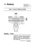
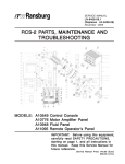
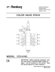
SERVICE MANUAL
FM-00-01.3
(Replaces FM-00-01.2)
July - 2007
RF-1 FLOWMETER
1
2
3
4
5
6
9
7
10
8
11
12
(76251-01)
IMPOR
TANT
IMPORT
ANT:: Before using this equipment,
carefully read SAFETY PRECAUTIONS,
starting on page 1, and all instructions in
this manual. Keep this Service Manual for
future reference.
Service Manual Price: €15.00
15.00 (Euro)
$20.00 (U.S.)
NOTE: This service manual has been superceded from service manual number FM-00-01.2 to service
manual number FM-00-01.3
FM-00-01.3. Reasons for this change are noted under “Manual Change Summary”
inside the back cover of this manual.
FM-00-01.3
RF-1 Flowmeter - Contents
CONTENTS
PAGE
SAFETY:
1-6
SAFETY PRECAUTIONS........................................................................................................... 1
HAZARDS / SAFEGUARDS....................................................................................................... 2-5
INTRODUCTION:
7-8
DESCRIPTIONS......................................................................................................................... 7
FLOW RATE ACCURACY.......................................................................................................... 7
REVERSE FLOW DETECTION................................................................................................. 7
FLUID PASSAGES..................................................................................................................... 7
SPECIFICATIONS...................................................................................................................... 7
INSTALLATION:
9-10
INSTALLATION........................................................................................................................... 9
MAINTENANCE:
11-12
FLOWMETER SERVICING........................................................................................................ 11
SERVICE..................................................................................................................................... 11
CALIBRATION............................................................................................................................. 12
AUTOMATIC CLEANING OF THE FLOWMETER.................................................................... 12
PARTS IDENTIFICATION:
13-14
RF-1 FLOWMETER / PARTS LIST............................................................................................ 13-14
WARRANTY POLICIES:
15
LIMITED WARRANTIES............................................................................................................. 15
FM-00-01.3
RF-1 Flowmeter - Safety
SAFETY
SAFETY PRECAUTIONS
Before operating, maintaining or servicing any
ITW Ransburg electrostatic coating system, read
and understand all of the technical and safety
literature for your ITW Ransburg products. This
manual contains information that is important for
you to know and understand. This information
relates to USER SAFETY and PREVENTING
EQUIPMENT PROBLEMS. To help you recognize this information, we use the following symbols. Please pay particular attention to these
sections.
A WARNING! states information to alert you
to a situation that might cause serious injury
if instructions are not followed.
A CAUTION! states information that tells
how to prevent damage to equipment or how
to avoid a situation that might cause minor
injury.
A NOTE is information relevant to the procedure in progress.
!
WARNING
> The user MUST read and be familiar with
the Safety Section in this manual and the
ITW Ransburg safety literature therein identified.
> This manual MUST be read and thoroughly understood by ALL personnel who
operate, clean, or maintain this equipment!
Special care should be taken to ensure the
the WARNINGS and safety requirements
for oprating and servicing the equipment are
followed. The user should be aware of and
adhere to ALL local building and fire codees
and ordinances as well as NFPA-33
NFPA-33, prior
to installing, operating, and/or servicing this
equipment.
!
WARNING
> The hazards shown on the following page
may occur during the normal use of this
equipment. Please read the hazard chart
beginning on page 2.
While this manual lists standard specifications
and service procedures, some minor deviations
may be found between this literature and your
equipment. Differences in local codes and plant
requirements, material delivery requirements, etc.,
make such variations inevitable. Compare this
manual with your system installation drawings
and appropriate ITW Ransburg equipment manuals to reconcile such differences.
Careful study and continued use of this manual will
provide a better understanding of the equipment
and process, resulting in more efficient operation,
longer trouble-free service and faster, easier troubleshooting. If you do not have the manuals and
safety literature for your Ransburg system, contact your local ITW Ransburg representative or
ITW Ransburg.
1
FM-00-01.3
RF-1 Flowmeter - Safety
AREA
HAZARD
SAFEGUARDS
Tells where hazards
may occur.
Tells what the hazard is.
Tells how to avoid the hazard.
Spray Area
Fire Hazard
Fire extinguishing equipment must be present in the
spray area and tested periodically.
Improper or inadequate operation
and maintenance procedures will Spray areas must be kept clean to prevent the
cause a fire hazard.
accumulation of combustible residues.
Protection against inadvertent
arcing that is capable of causing
fire or explosion is lost if any safety
interlocks are disabled during
operation. Frequent power supply
shutdown indicates a problem in
the system requiring correction.
Smoking must never be allowed in the spray area.
The high voltage supplied to the atomizer must be
turned off prior to cleaning, flushing or maintenance.
When using solvents for cleaning:
Those used for equipment flushing should have flash
points equal to or higher than those of the coating
material.
Those used for general cleaning must have flash
points above 100°F (37.8°C).
Spray booth ventilation must be kept at the rates
required by NFPA-33, OSHA, and local codes. In
addition, ventilation must be maintained during
cleaning operations using flammable or combustible
solvents.
Electrostatic arcing must be prevented.
Test only in areas free of combustible material.
Testing may require high voltage to be on, but only as
instructed.
Non-factory replacement parts or unauthorized
equipment modifications may cause fire or injury.
If used, the key switch bypass is intended for use
only during setup operations. Production should
never be done with safety interlocks disabled.
Never use equipment intended for use in waterborne
installations to spray solvent based materials.
Paint process and equipment should be set up and
operated in accordance with NFPA-33, NEC, and
OSHA requirements.
FM-00-01.3
2
RF-1 Flowmeter - Safety
AREA
Tells where hazards
may occur.
General Use and
Maintenance
HAZARD
SAFEGUARDS
Tells what the hazard is.
Tells how to avoid the hazard.
Improper operation or maintenance Personnel must be given training in accordance with
may create a hazard.
the requirements of NFPA-33.
Personnel must be properly trained Instructions and safety precautions must be read
in the use of this equipment.
and understood prior to using this equipment.
Comply with appropriate local, state, and national
codes governing ventilation, fire protection, operation
maintenance, and housekeeping. Reference OSHA,
NFPA-33, and your insurance company requirements.
Electrical
Equipment
High voltage equipment is utilized.
Arcing in areas of flammable or
combustible materials may occur.
Personnel are exposed to high
voltage during operation and
maintenance.
The power supply, optional remote control cabinet,
and all other electrical equipment must be located
outside Class I or II, Division 1 and 2 hazardous
areas (refer to NFPA-33).
Turn the power supply OFF before working on the
equipment.
Protection against inadvertent
arcing that may cause a fire or Test only in areas free of flammable or combustible
explosion is lost if safety circuits material.
are disabled during operation.
Testing may require high voltage to be on, but only
Frequent power supply shutdown as instructed.
indicates a problem in the system
Production should never be done with the safety
which requires correction.
circuits disabled.
An electrical arc can ignite coating
materials and cause a fire or Before turning the high voltage on, make sure no
objects are within the sparking distance.
explosion.
Explosion
Hazard /
Incompatible
Materials
3
Halogenated
hydrocarbon
solvents for example: methylene
chloride and 1,1,1,-Trichloroethane are not chemically
compatible with the aluminum that
might be used in many system
components. The chemical
reaction caused by these solvents
reacting with aluminum can
become violent and lead to an
equipment explosion.
Aluminum is widely used in other spray application
equipment - such as material pumps, regulators,
triggering valves, etc. Halogenated hydrocarbon
solvents must never be used with aluminum
equipment during spraying, flushing, or cleaning.
Read the label or data sheet for the material you
intend to spray. If in doubt as to whether or not a
coating or cleaning material is compatible, contact
your material supplier. Any other type of solvent may
be used with aluminum equipment.
FM-00-01.3
RF-1 Flowmeter - Safety
AREA
Tells where hazards
may occur.
General Use and
Maintenance
HAZARD
SAFEGUARDS
Tells what the hazard is.
Tells how to avoid the hazard.
Use of hand tools may cause
cumulative trauma disorders
(CTD's). CTD's or musculoskeletal
disorders, involve damage to the
hands, wrists, elbows, shoulders,
neck and back. Carpal tunnel
syndrome and tendinitis (such as
tennis elbow or rotator cuff
syndrome) are examples of CTD's.
CTD's when using hand tools, tend
to affect the upper extremities.
Factors which may increase the
risk of developing a CTD include:
1. High frequency of the activity.
Risk is reduced by avoiding or lessening the listed
hazards.
CTD's can also be caused by such activities as
sewing, golf, tennis and bowling, to name a few.
Pain, tingling, or numbness in the shoulder, forearm,
wrists, hands, or fingers, especially during the night,
may be early symptoms of a CTD. Do not ignore
them. Should you experience any such symptoms,
see a physician immediately. Other early symptoms
may include vague discomfort in the hand, loss of
manual dexterity, and nonspecific pain in the arm.
Ignoring early symptoms and continued repetitive
use of the arm, wrist and hand can lead to serious
disability.
2. Excessive force, such as
gripping, pinching or pressing
with the hands and fingers.
3. Extreme or awkward finger,
wrist or arm positions.
4. Excessive duration of the
activity.
5. Tool vibration.
6. Repeated pressure on a
body part.
7. Working in cold temperatures.
Toxic Substances Certain material may be harmful if Follow the requirements of the Material Safety Data
inhaled, or if there is contact with Sheet supplied by coating material manufacturer.
the skin.
Adequate exhaust must be provided to keep the air
free of accumulations of toxic materials.
Use a mask or respirator whenever there is a chance
of inhaling sprayed materials. The mask must be
compatible with the material being sprayed and its
concentration. Equipment must be as prescribed by
an industrial hygienist or safety expert, and be
NIOSH approved.
FM-00-01.3
4
RF-1 Flowmeter - Safety
AREA
Tells where hazards
may occur.
General Use and
Maintenance
HAZARD
SAFEGUARDS
Tells what the hazard is.
Tells how to avoid the hazard.
Improper operation or maintenance Personnel must be given training in accordance with
may create a hazard.
the requirements of NFPA-33.
Personnel must be properly trained Instructions and safety precautions must be read
in the use of this equipment.
and understood prior to using this equipment.
Comply with appropriate local, state, and national
codes governing ventilation, fire protection, operation
maintenance, and housekeeping. Reference OSHA,
NFPA-33, and your insurance company requirements.
Always turn power to the power supply OFF, unplug
the electrical cord from its outlet, and remove the
front panel fuse, before opening the power supply
door. If necessary, lock the power supply out so that
it cannot be turned ON until the work is finished.
Whenever removing high voltage cables from
equipment, ground the contact end of the cable by
holding the cable such that the contact touches earth
ground for several seconds. Do not touch the contact
until it has been grounded. This will reduce the
possibility of residual charge causing electrical shock.
The High Voltage Multiplier Assembly contains energy
storage components that can cause serious shock
injury, and therefore is not field repairable. Warranty
will be voided if the High Voltage Multiplier seal is
broken. If the High Voltage Multiplier is defective
contact your authorized ITW Ransburg representative
for exchange or repair.
The High Voltage Multiplier and high voltage cable
contain significant capacitance that will store charge.
Allow approximately 10 seconds for this charge to
bleed off before opening the cabinet door or removing
the high voltage cable from the power supply or
spraygun.
5
FM-00-01.3
RF-1 Flowmeter - Safety
NOTES
FM-00-01.3
6
RF-1 Flowmeter - Introduction
INTRODUCTION
DESCRIPTIONS
The RF-1 Flowmeter has been developed for
precise metering and monitoring of fluid flows. The
flowmeter in many cases, surpasses the
performance of meters currently used.
SPECIFICA
TIONS
SPECIFICATIONS
Material Viscosity Range
Flow Rate:
.01-.50 GPM
(.04-1.9 LPM)
Accuracy:
+/- 0.5%
(system dependent)
FLOW RA
TE ACCURACY
RATE
Flow rate accuracies of 0.5% are not uncommon
with many fluids if the flowmeters are calibrated at
or near the expected flow rates. Even with wide
flow rate swings (such as when used with robots
under analog control) accuracies of +/- 2% are
achievable.
REVERSE FLOW
DETECTION
Sensors are of the quadrature type, which allows
reverse flow detection, if necessary. Under
conditions where reverse flow detection is not
necessary, only one sensor output is used, leaving
the second sensor output as a spare output that
can be used if the first sensor should ever fail.
FLUID P
ASSAGES
PASSAGES
The RF-1 requires 3/8” AN male fittings. This style
fitting eliminates flow “dead space” and also
eliminates the need for specially designed fittings
or Teflon inserts. By creating a streamline fluid
passage, color change time of the meter is
improved.
7
Working Pressure: 500 psi (345 bar)
MWP @ 100°F
Temperature:
180°F (85°C)
Signal Output:
2 Channel Quadrature
30,000 PPG (8100 PPL)
Power:
8-24 VDC
Materials
Body:
303 Stainless Steel
Gears:
Stainless Steel
(Hardened)
Bushings:
Carbide
Shafts:
Carbide
Seal:
Teflon
Filtration:
100 Mesh (maximum)
Connections:
Threaded 3/8” AN (F)
Weight:
4.5 lbs. (2.0 Kg)
FM-00-01.3
RF-1 Flowmeter - Introduction
NOTES
FM-00-01.3
8
RF-1 Flowmeter - Installation
INST
ALLA
TION
INSTALLA
ALLATION
The unit may be mounted using the bolt pattern
shown in Figure 1. [2] 1/4 - 20 bolts should be used.
Always mount the flowmeter with the gear faces
perpendicular to the horizon of the earth (i.e.
Vertical). This minimizes the effect of gravity on
the gears. The direction of flow must be plumbed
as marked on the side label of the meter. The fluid
inlet is opposite the sensor connection.
NOTES
The meter should be plumbed such that flow enters
at the bottom of the meter and exits at the top. This
eliminates any possibility of air entrepment in the
meter.
!
WARNING
> This meter may be installed in Class I,
Division I, Group D locations when used in
conjunction with the proper Zenner Barrier.
9
FM-00-01.3
RF-1 Flowmeter - Installation
NOTES
FM-00-01.3
10
RF-1 Flowmeter - Maintenance
MAINTENANCE
FLOWMETER
SERVICING
Flowmeter problems can be caused by
improperly filtered fluid. Particulates in the
fluid can cause gear binding, resulting in improper
signals for the actual flow rate. Maintain the fluid
filters according to the instructions from the filter
manufacturer. If repeated disassembly and
cleaning for removal of solids and particulates
occurs, inspect the entire fluid supply system and
evaluate the system cleaning cycle.
Fluid back-up, that is reverse flow, can cause
reacted/catalyzed material to enter the flow-meter.
Reverse flow will be detected by the 2k controls
and the system will shut down. The flowmeter
should be cleaned immediately, before the fluid
sets-up.
Under normal operation the magnetic sensors or
electrical connections will not require replacement.
SERVICE
Disconnect sensor cable [1] from the flowmeter
sensor [2]. Remove meter for service to a suitable
clean area to perform maintenance. Using a 3/16”
Allen wrench, remove all 10 [3] bolts. Pull the
sensor section STRAIGHT apart from the gear
pocket section. If the body halves do not slide
apart easily, DO NOT pry them apart with
screwdrivers, etc. Rather, replace a few of the
bolts and only thread them in a few turns, then tap
the top of the bolts with a soft mallet, while holding
the top half of the body. Pull the gears and pins
from the gear pocket section. Clean and replace
worn parts as necessary. Install new teflon o-ring
[7]. Install all parts the order they were removed.
Install flated portion of shafts [5] toward gears (see
Figure 1). Push the two covers together, aligning
the pins and holes by hand.
TORQUE SEQUENCE
9
2
MOUNTING FOOTPRINT
1/4-20 THREAD
7
6
4
3
3/16" ALLEN HEAD
5
8
10
1
SENSOR SECTION
GEAR POCKET SECTION
ALIGNMENT PINS
FLUID OUTLET
ALIGNMENT HOLE
FLUID
FLOW
DIRECTION
FLUID INLET
RELIEF CUT
RELIEF CUT
Figure 1:
Views of Flow Meter Body
NOTE
There is only one way to install the sensor section and the gear pocket section.
Snug all screws down. Tighten the screws in the
sequence pattern shown in Figure 1 to 13 lbs•ft
torque. This is a cross pattern to insure proper
gasket sealing.
Figure 2: View of Flated Portion of
Shafts
11
FM-00-01.3
RF-1 Flowmeter - Maintenance
CALIBRA
TION
CALIBRATION
NOTES
Refer to appropriate associated equipment for
calibration procedure.
AUT
OMA
TIC CLEANING
AUTOMA
OMATIC
OF THE FLOWMETER
Fluid Line Air Purges
Air purges are often used in automatic coating
operations for rapid color changes and to minimize
the amount of solvent required to flush-out the old
color. Special considerations must be made
when using air purges through the flowmeter.
1. Air purges do not provide the lubrication the
flowmeter gears require. Lubrication is normally
provided by the metered fluid or solvent.
2. Air purges can cause some coating materials
to “dry” on the flowmeter shafts and gears thus
affecting the performance characteristics of the
flowmeter, especially when water-based materials
are used.
3. Excessively long air purges will cause
premature gear and shaft failure.
4. All clean cycles should begin with a solvent
push to prevent drying of coating material on
flowmeter parts.
5. Solvent and air “chop” cycles are recommended
as the most efficient way of flushing flowmeters.
6. Air purge cycles are not recommended in
water-based applications.
FM-00-01.3
12
RF-1 Flowmeter - Parts Identification
PAR
TS IDENTIFICA
TION
ARTS
IDENTIFICATION
1
2
3
4
5
6
9
7
10
8
11
12
Figure 3:
13
RF-1 Flowmeter
FM-00-01.3
RF-1 Flowmeter - Parts Identification
RF-1 FLOWMETER - P
AR
TS LIST (F
igure 3)
PAR
ARTS
(Figure
Item # Part #
Description
1
2
TR-SSEH-585
76252-00
Electrical Connector
Sensor Assembly
3
4
5
6
1/4” -20 x 1-1/4” L.
N/A
76271-00
76270-00
Socket Hd. Cap Screw
Upper Housing
Shaft
Gear
7
8
9
76272-00
N/A
N/A
Teflon O-Ring
Lower Housing
Alignment Pin
10
11
LSF10033-00
77104-00
77105-00
76804-00 (-01)
3/8” AN x 3/8” ODT Fit.
3/8” AN x 3/8” NPSM (m)
3/8” AN x 1/4” NPSM (m)
3/8” OD SS Tubing
12
76850-00
Fitting Kit
FM-00-01.3
Notes
Same connection as TR-SSEH series flowmeters
See Service Bulletin #98-11 (revised) for
interchangeability with TR-SSEH-793-2 sensors
Must be grade 8 or better
Cannot be purchased seperately
Interchangeable with TR-SSEH-604
Stamped with an ‘F’ or ‘G’ to distinguish from
TR-SSEH-603 gears
Cannot be purchased seperately
Pins press fitted in and cannot be removed or
replaced.
Optional fitting
Optional fitting
Optional fitting
Used when replacing TR-SSEH series flowmeters
on 2k Controls (or 2k880) fluid panels.
Used when 1/4” OD tubing is required or preferred
14
RF-1 Flowmeter - Warranty Policies
WARRANTY POLICIES
LIMITED W
ARRANTY
WARRANTY
ITW Ransburg will replace or repair without
charge any part and/or equipment that fails within
the specified time (see below) because of faulty
workmanship or material, provided that the
equipment has been used and maintained in
accordance with ITW Ransburg’s written safety
and operating instructions, and has been used
under normal operating conditions. Normal wear
items are excluded.
THE USE OF OTHER THAN ITW
RANSBURG APPROVED PARTS VOIDS
ALL WARRANTIES.SPARE PARTS: One
hundred and eighty (180) days from date of
purchase, except for rebuilt parts (any part number
ending in “R”) for which the warranty period is
ninety (90) days.
SPARE PARTS: One hundred and eighty (180)
days from date of purchase, except for rebuilt
parts (any part number ending in “R”) for which the
warranty period is ninety (90) days.
ITW RANSBURG’S ONLY OBLIGATION
UNDER THIS WARRANTY IS TO REPLACE
PARTS THAT HAVE FAILED BECAUSE
OF
FAULTY
WORKMANSHIP
OR
MATERIALS. THERE ARE NO IMPLIED
WARRANTIES NOR WARRANTIES OF
EITHER MERCHANTABILITY OR FITNESS
FOR A PARTICULAR PURPOSE. ITW
RANSBURG ASSUMES NO LIABILITY FOR
INJURY, DAMAGE TO PROPERTY OR
FOR CONSEQUENTIAL DAMAGES FOR
LOSS OF GOODWILL OR PRODUCTION
OR INCOME, WHICH RESULT FROM USE
OR MISUSE OF THE EQUIPMENT BY
PURCHASER OR OTHERS.
EXCLUSIONS:
OTHERS.EXCLUSIONS:
EXCLUSIONS:
If, in ITW Ransburg’s opinion the warranty item in
question, or other items damaged by this part was
improperly installed, operated or maintained, ITW
Ransburg will assume no responsibility for repair
or replacement of the item or items. The purchaser,
therefore will assume all responsibility for any cost
of repair or replacement and service related costs
if applicable.
EQUIPMENT: When purchased as a complete
unit, (i.e., guns, power supplies, control units,
etc.), is one (1) year from date of purchase.
WRAPPING
THE
APPLICATOR
IN
PLASTIC, SHRINK-WRAP, ETC., WILL
VOID THIS WARRANTY.
15
FM-00-01.3
MANUAL CHANGE SUMMAR
Y
SUMMARY
This manual was published to supercede Service
Manual FM-00-01.1 to make the following
changes:
1. Added “Service Manual Price” to the “Front
Cover”.
2. Added “Safety Section”.
3. Added “Warranty Section”.
4. Added “Manual Change Summary” page.
5. Added “Service Manual Price” to the “Back
Cover”.
6. Revised “Contact Information” on the “Back
Cover”.
FM-00-01.3
Service Manual Price: €15.00
15.00 (Euro)
$20.00 (U.S.)
Manufacturing
1910 North Wayne Street
Angola, Indiana 46703-9100
Telephone: 260/665-8800
Fax: 260/665-8516
Technical/Service Assistance
Automotive Assembly and Tier I
Industrial Systems
Ransburg Guns
www.itwransburg.com
Telephone: 800/ 626-3565 Fax: 419/ 470-2040
Telephone: 800/ 233-3366 Fax: 419/ 470-2071
Telephone: 800/ 233-3366 Fax: 419/ 470-2071
Technical Support Representative will direct you to the appropriate telephone
number for ordering Spare Parts.
© 2007 Illinois Tool Works Inc. All rights reserved.
Models and specifications subject to change without notice.
Form No. FM-00-01.3
Litho in U.S.A.
07/07