1
StorageTek™
Host Software
Component (HSC)
MVS software
Operator’s Guide
Part Number: 312597201
Revision:E
Version: 6.1
Host Software Component
(MVS Implementation)
Operator’s Guide
Release 6.1
312597201
Copyright © 2009 Sun Microsystems, Inc., 4150 Network Circle, Santa Clara, California 95054, U.S.A. All rights reserved.
U.S. Government Rights - Commercial Software. Government users are subject to the Sun Microsystems, Inc. standard license
agreement and applicable provisions of the FAR and its supplements.
Sun, Sun Microsystems, the Sun logo, Sun Fire and The Network Is The Computer are trademarks or registered trademarks of Sun
Microsystems, Inc. or its subsidiaries, in the U.S. and other countries.
Products covered by and information contained in this service manual are controlled by U.S. Export Control laws and may be subject to
the export or import laws in other countries. Nuclear, missile, chemical biological weapons or nuclear maritime end uses or end users,
whether direct or indirect, are strictly prohibited. Export or reexport to countries subject to U.S. embargo or to entities identified on U.S.
export exclusion lists, including, but not limited to, the denied persons and specially designated nationals lists is strictly prohibited.
DOCUMENTATION IS PROVIDED "AS IS" AND ALL EXPRESS OR IMPLIED CONDITIONS, REPRESENTATIONS AND
WARRANTIES, INCLUDING ANY IMPLIED WARRANTY OF MERCHANTABILITY, FITNESS FOR A PARTICULAR
PURPOSE OR NON-INFRINGEMENT, ARE DISCLAIMED, EXCEPT TO THE EXTENT THAT SUCH DISCLAIMERS ARE
HELD TO BE LEGALLY INVALID.
Copyright © 2009 Sun Microsystems, Inc., 4150 Network Circle, Santa Clara, California 95054, États-Unis. Tous droits réservés.
Droits du gouvernement des États-Unis. Logiciel Commercial. Les droits des utilisateur du gouvernement des États-Unis sont soumis
aux termes de la licence standard Sun Microsystems et aux conditions appliquées de la FAR et de ces compléments.
Sun, Sun Microsystems, le logo Sun, Sun Fire et The Network Is The Computer sont des marques de fabrique ou des marques enregistrées
de Sun Microsystems, Inc. ou ses filiales, aux États-Unis et dans d'autres pays.
Les produits qui font l'objet de ce manuel d'entretien et les informations qu'il contient sont regis par la legislation americaine en matière
de contrôle des exportations et peuvent être soumis au droit d'autres pays dans le domaine des exportations et importations. Les
utilisations finales , ou utilisateurs finaux, pour des armes nucleaires, des missiles, des armes biologiques et chimiques ou du nucleaire
maritime, directement ou indirectement, sont strictement interdites. Les exportations ou reexportations vers des pays sous embargo des
États-Unis, ou vers des entites figurant sur les listes d'exclusion d'exportation americaines, y compris, mais de maniere non exclusive, la
liste de personnes qui font objet d'un ordre de ne pas participer, d'une façon directe ou indirecte, aux exportations de des produits ou des
services qui sont regi par la legislation americaine sur le contrôle des exportations et la liste de ressortissants specifiquement designes,
sont rigoureusement interdites.
LA DOCUMENTATION EST FOURNIE "EN L'ÉTAT" ET TOUTES AUTRES CONDITIONS, DECLARATIONS ET GARANTIES
EXPRESSES OU TACITES SONT FORMELLEMENT EXCLUES, DANS LA MESURE AUTORISEE PAR LA LOI APPLICABLE,
Y COMPRIS NOTAMMENT TOUTE GARANTIE IMPLICITE RELATIVE À LA QUALITE MARCHANDE, À L'APTITUDE À
UNE UTILISATION PARTICULIERE OU À L'ABSENCE DE CONTREFAÇON.
Document Effectivity
EC Number
Date
Doc Kit
Number
Type
Effectivity
This document applies to the
Host Software Component for
MVS (MVS/HSC), Version 6.1.
132084
February, 2005
---
First Edition
132553
February, 2006
---
Revision B
---
April, 2008
---
Revision C
---
September, 2008
---
Revision D
---
May, 2009
---
Revision E
Document Effectivity iii
Rev. E, 5/31/09 - 312597201
iv MVS/HSC 6.1 Operator’s Guide
Rev. E, 5/31/09 - 312597201
Contents
What’s New With This Release? . . . . . . . . . . . . . . . . . . . . . . . . . . . . . . . . . . . . . . . . . . . . . .
xv
Preface . . . . . . . . . . . . . . . . . . . . . . . . . . . . . . . . . . . . . . . . . . . . . . . . . . . . . . . . . . . . . . . . . . .
xxiii
Scope . . . . . . . . . . . . . . . . . . . . . . . . . . . . . . . . . . . . . . . . . . . . . . . . . . . . . . . . . . . . . . . . . . . . . . . . xxiii
Intended Audience . . . . . . . . . . . . . . . . . . . . . . . . . . . . . . . . . . . . . . . . . . . . . . . . . . . . . . . . . . . . . . xxiii
Organization of this Guide . . . . . . . . . . . . . . . . . . . . . . . . . . . . . . . . . . . . . . . . . . . . . . . . . . . . . . . . xxiii
How to Use This Guide . . . . . . . . . . . . . . . . . . . . . . . . . . . . . . . . . . . . . . . . . . . . . . . . . . . . . . . . . . xxiv
References to HSC Product Releases . . . . . . . . . . . . . . . . . . . . . . . . . . . . . . . . . . . . . . . . . . . . . . . . xxiv
Related Publications . . . . . . . . . . . . . . . . . . . . . . . . . . . . . . . . . . . . . . . . . . . . . . . . . . . . . . . . . . . . . xxiv
Additional Information . . . . . . . . . . . . . . . . . . . . . . . . . . . . . . . . . . . . . . . . . . . . . . . . . . . . . . . . . . .
xxv
Sun’s External Web Site . . . . . . . . . . . . . . . . . . . . . . . . . . . . . . . . . . . . . . . . . . . . . . . . . . . . .
xxv
Customer Resource Center . . . . . . . . . . . . . . . . . . . . . . . . . . . . . . . . . . . . . . . . . . . . . . . . . . .
xxv
Partners Site . . . . . . . . . . . . . . . . . . . . . . . . . . . . . . . . . . . . . . . . . . . . . . . . . . . . . . . . . . . . . . .
xxv
Hardcopy Publications . . . . . . . . . . . . . . . . . . . . . . . . . . . . . . . . . . . . . . . . . . . . . . . . . . . . . .
xxv
Customer Support . . . . . . . . . . . . . . . . . . . . . . . . . . . . . . . . . . . . . . . . . . . . . . . . . . . . . . . . . . xxvi
Customer-initiated Maintenance . . . . . . . . . . . . . . . . . . . . . . . . . . . . . . . . . . . . . . . . . . . . . . xxvi
Sun’s Worldwide Offices . . . . . . . . . . . . . . . . . . . . . . . . . . . . . . . . . . . . . . . . . . . . . . . . . . . . xxvii
Chapter 1. General Information . . . . . . . . . . . . . . . . . . . . . . . . . . . . . . . . . . . . . . . . . . . . . . .
1
Introduction . . . . . . . . . . . . . . . . . . . . . . . . . . . . . . . . . . . . . . . . . . . . . . . . . . . . . . . . . . . . . . . . . . .
System Overview . . . . . . . . . . . . . . . . . . . . . . . . . . . . . . . . . . . . . . . . . . . . . . . . . . . . . . . . . . . . . . .
Control Path . . . . . . . . . . . . . . . . . . . . . . . . . . . . . . . . . . . . . . . . . . . . . . . . . . . . . . . . . . . . . . .
Data Path . . . . . . . . . . . . . . . . . . . . . . . . . . . . . . . . . . . . . . . . . . . . . . . . . . . . . . . . . . . . . . . . .
System Components . . . . . . . . . . . . . . . . . . . . . . . . . . . . . . . . . . . . . . . . . . . . . . . . . . . . . . . . . . . . .
HSC . . . . . . . . . . . . . . . . . . . . . . . . . . . . . . . . . . . . . . . . . . . . . . . . . . . . . . . . . . . . . . . . . . . .
SMC . . . . . . . . . . . . . . . . . . . . . . . . . . . . . . . . . . . . . . . . . . . . . . . . . . . . . . . . . . . . . . . . . . . .
Library Management Unit . . . . . . . . . . . . . . . . . . . . . . . . . . . . . . . . . . . . . . . . . . . . . . . . . . .
Library Storage Module . . . . . . . . . . . . . . . . . . . . . . . . . . . . . . . . . . . . . . . . . . . . . . . . . . . . .
HSC-to-ACS Operating Modes . . . . . . . . . . . . . . . . . . . . . . . . . . . . . . . . . . . . . . . . . . . . . . . . . . . .
Connected Mode . . . . . . . . . . . . . . . . . . . . . . . . . . . . . . . . . . . . . . . . . . . . . . . . . . . . . . . . . . .
Disconnected Mode . . . . . . . . . . . . . . . . . . . . . . . . . . . . . . . . . . . . . . . . . . . . . . . . . . . . . . . . .
LSM Operating Modes . . . . . . . . . . . . . . . . . . . . . . . . . . . . . . . . . . . . . . . . . . . . . . . . . . . . . . . . . . .
Automatic Mode . . . . . . . . . . . . . . . . . . . . . . . . . . . . . . . . . . . . . . . . . . . . . . . . . . . . . . . . . . .
Manual Mode . . . . . . . . . . . . . . . . . . . . . . . . . . . . . . . . . . . . . . . . . . . . . . . . . . . . . . . . . . . . .
1
2
2
3
4
4
4
4
6
9
9
9
11
11
11
Chapter 2. Commands, Control Statements, and Utilities . . . . . . . . . . . . . . . . . . . . . . . . .
13
Overview . . . . . . . . . . . . . . . . . . . . . . . . . . . . . . . . . . . . . . . . . . . . . . . . . . . . . . . . . . . . . . . . . . . . .
13
Contents v
Rev. E, 5/31/09 - 312597201
Virtual Storage Manager (VSM) Support . . . . . . . . . . . . . . . . . . . . . . . . . . . . . . . . . . . . . . . . . . . .
Overview of Command Syntax . . . . . . . . . . . . . . . . . . . . . . . . . . . . . . . . . . . . . . . . . . . . . . . . . . . .
Operator Command Syntax Rules . . . . . . . . . . . . . . . . . . . . . . . . . . . . . . . . . . . . . . . . . . . . .
Syntax Flow Diagrams . . . . . . . . . . . . . . . . . . . . . . . . . . . . . . . . . . . . . . . . . . . . . . . . . . . . . . . . . .
Specifying Commands . . . . . . . . . . . . . . . . . . . . . . . . . . . . . . . . . . . . . . . . . . . . . . . . . . . . . .
Variables . . . . . . . . . . . . . . . . . . . . . . . . . . . . . . . . . . . . . . . . . . . . . . . . . . . . . . . . . . . . . . . .
Delimiters . . . . . . . . . . . . . . . . . . . . . . . . . . . . . . . . . . . . . . . . . . . . . . . . . . . . . . . . . . . . . . . .
Flow Lines . . . . . . . . . . . . . . . . . . . . . . . . . . . . . . . . . . . . . . . . . . . . . . . . . . . . . . . . . . . . . . .
Single Required Choice . . . . . . . . . . . . . . . . . . . . . . . . . . . . . . . . . . . . . . . . . . . . . . . . . . . . .
Single Optional Choice . . . . . . . . . . . . . . . . . . . . . . . . . . . . . . . . . . . . . . . . . . . . . . . . . . . . .
Defaults . . . . . . . . . . . . . . . . . . . . . . . . . . . . . . . . . . . . . . . . . . . . . . . . . . . . . . . . . . . . . . . . .
Repeat Symbol . . . . . . . . . . . . . . . . . . . . . . . . . . . . . . . . . . . . . . . . . . . . . . . . . . . . . . . . . . . .
Syntax Continuation (Fragments) . . . . . . . . . . . . . . . . . . . . . . . . . . . . . . . . . . . . . . . . . . . . .
How to Read Syntax Flow Diagrams . . . . . . . . . . . . . . . . . . . . . . . . . . . . . . . . . . . . . . . . . .
Library Identification . . . . . . . . . . . . . . . . . . . . . . . . . . . . . . . . . . . . . . . . . . . . . . . . . . . . . . . . . . .
How to Specify a CAPid . . . . . . . . . . . . . . . . . . . . . . . . . . . . . . . . . . . . . . . . . . . . . . . . . . . .
Ranges and Lists . . . . . . . . . . . . . . . . . . . . . . . . . . . . . . . . . . . . . . . . . . . . . . . . . . . . . . . . . . . . . .
HSC Commands and Control Statements . . . . . . . . . . . . . . . . . . . . . . . . . . . . . . . . . . . . . . . . . . . .
HSC Commands . . . . . . . . . . . . . . . . . . . . . . . . . . . . . . . . . . . . . . . . . . . . . . . . . . . . . . . . . .
Control Statements . . . . . . . . . . . . . . . . . . . . . . . . . . . . . . . . . . . . . . . . . . . . . . . . . . . . . . . . .
HSC Service Levels . . . . . . . . . . . . . . . . . . . . . . . . . . . . . . . . . . . . . . . . . . . . . . . . . . . . . . . .
Allocation (ALLOC) Command and Control Statement . . . . . . . . . . . . . . . . . . . . . . . . . . . .
CAP Preference (CAPPref) Command and Control Statement . . . . . . . . . . . . . . . . . . . . . . .
CDS Enable/Disable Command . . . . . . . . . . . . . . . . . . . . . . . . . . . . . . . . . . . . . . . . . . . . . . .
CLEAN Command . . . . . . . . . . . . . . . . . . . . . . . . . . . . . . . . . . . . . . . . . . . . . . . . . . . . . . . .
Communications Path (COMMPath) Command and Control Statement . . . . . . . . . . . . . . .
DISMOUNT Command . . . . . . . . . . . . . . . . . . . . . . . . . . . . . . . . . . . . . . . . . . . . . . . . . . . . .
DISPLAY Command . . . . . . . . . . . . . . . . . . . . . . . . . . . . . . . . . . . . . . . . . . . . . . . . . . . . . . .
DRAIN CAP Command . . . . . . . . . . . . . . . . . . . . . . . . . . . . . . . . . . . . . . . . . . . . . . . . . . . .
EJECT Command . . . . . . . . . . . . . . . . . . . . . . . . . . . . . . . . . . . . . . . . . . . . . . . . . . . . . . . . .
ENTER Command . . . . . . . . . . . . . . . . . . . . . . . . . . . . . . . . . . . . . . . . . . . . . . . . . . . . . . . . .
JOURNAL Command . . . . . . . . . . . . . . . . . . . . . . . . . . . . . . . . . . . . . . . . . . . . . . . . . . . . . .
MNTD (Mount/Dismount Options) Command and Control Statement . . . . . . . . . . . . . . . .
MODIFY Command . . . . . . . . . . . . . . . . . . . . . . . . . . . . . . . . . . . . . . . . . . . . . . . . . . . . . . .
MONITOR Command . . . . . . . . . . . . . . . . . . . . . . . . . . . . . . . . . . . . . . . . . . . . . . . . . . . . . .
MOUNT Command . . . . . . . . . . . . . . . . . . . . . . . . . . . . . . . . . . . . . . . . . . . . . . . . . . . . . . . .
MOVE Command . . . . . . . . . . . . . . . . . . . . . . . . . . . . . . . . . . . . . . . . . . . . . . . . . . . . . . . . .
OPTION Command and Control Statement . . . . . . . . . . . . . . . . . . . . . . . . . . . . . . . . . . . . .
RECOVER Host Command . . . . . . . . . . . . . . . . . . . . . . . . . . . . . . . . . . . . . . . . . . . . . . . . . .
RELease CAP Command . . . . . . . . . . . . . . . . . . . . . . . . . . . . . . . . . . . . . . . . . . . . . . . . . . . .
SENTER Command . . . . . . . . . . . . . . . . . . . . . . . . . . . . . . . . . . . . . . . . . . . . . . . . . . . . . . . .
SRVlev (Service Level) Command . . . . . . . . . . . . . . . . . . . . . . . . . . . . . . . . . . . . . . . . . . . .
Stop Monitoring (STOPMN) Command . . . . . . . . . . . . . . . . . . . . . . . . . . . . . . . . . . . . . . . .
SWITCH Command . . . . . . . . . . . . . . . . . . . . . . . . . . . . . . . . . . . . . . . . . . . . . . . . . . . . . . .
TRACE Command . . . . . . . . . . . . . . . . . . . . . . . . . . . . . . . . . . . . . . . . . . . . . . . . . . . . . . . . .
TRACELKP Command . . . . . . . . . . . . . . . . . . . . . . . . . . . . . . . . . . . . . . . . . . . . . . . . . . . . .
vi MVS/HSC 6.1 Operator’s Guide
Rev. E, 5/31/09 - 312597201
13
14
14
16
16
16
16
17
18
18
18
19
19
19
21
22
25
30
30
31
31
34
39
45
49
51
58
60
138
142
157
162
164
172
179
181
188
196
203
205
207
210
212
214
215
220
User Exit (UEXIT) Command and Control Statement . . . . . . . . . . . . . . . . . . . . . . . . . . . . . .
VARY Station Command . . . . . . . . . . . . . . . . . . . . . . . . . . . . . . . . . . . . . . . . . . . . . . . . . . . .
VIEW Command . . . . . . . . . . . . . . . . . . . . . . . . . . . . . . . . . . . . . . . . . . . . . . . . . . . . . . . . . . .
WARN Command . . . . . . . . . . . . . . . . . . . . . . . . . . . . . . . . . . . . . . . . . . . . . . . . . . . . . . . . . .
Library Utilities Overview . . . . . . . . . . . . . . . . . . . . . . . . . . . . . . . . . . . . . . . . . . . . . . . . . . . . . . . .
Activities Report Utility . . . . . . . . . . . . . . . . . . . . . . . . . . . . . . . . . . . . . . . . . . . . . . . . . . . . .
Audit Utility . . . . . . . . . . . . . . . . . . . . . . . . . . . . . . . . . . . . . . . . . . . . . . . . . . . . . . . . . . . . . .
Backup Utility . . . . . . . . . . . . . . . . . . . . . . . . . . . . . . . . . . . . . . . . . . . . . . . . . . . . . . . . . . . . .
Database Decompile Utility . . . . . . . . . . . . . . . . . . . . . . . . . . . . . . . . . . . . . . . . . . . . . . . . . .
Directory Rebuild Utility . . . . . . . . . . . . . . . . . . . . . . . . . . . . . . . . . . . . . . . . . . . . . . . . . . . .
Eject Cartridge Utility . . . . . . . . . . . . . . . . . . . . . . . . . . . . . . . . . . . . . . . . . . . . . . . . . . . . . . .
Initialize Cartridge Utility . . . . . . . . . . . . . . . . . . . . . . . . . . . . . . . . . . . . . . . . . . . . . . . . . . . .
Journal Offload Utility . . . . . . . . . . . . . . . . . . . . . . . . . . . . . . . . . . . . . . . . . . . . . . . . . . . . . .
Mergecds Utility . . . . . . . . . . . . . . . . . . . . . . . . . . . . . . . . . . . . . . . . . . . . . . . . . . . . . . . . . . .
Move Utility . . . . . . . . . . . . . . . . . . . . . . . . . . . . . . . . . . . . . . . . . . . . . . . . . . . . . . . . . . . . . .
Performance Log Reblocker Utility . . . . . . . . . . . . . . . . . . . . . . . . . . . . . . . . . . . . . . . . . . . .
Reconfig Utility . . . . . . . . . . . . . . . . . . . . . . . . . . . . . . . . . . . . . . . . . . . . . . . . . . . . . . . . . . . .
Restore Utility . . . . . . . . . . . . . . . . . . . . . . . . . . . . . . . . . . . . . . . . . . . . . . . . . . . . . . . . . . . . .
Scratch Conversion Utilities . . . . . . . . . . . . . . . . . . . . . . . . . . . . . . . . . . . . . . . . . . . . . . . . . .
Scratch Redistribution Utility . . . . . . . . . . . . . . . . . . . . . . . . . . . . . . . . . . . . . . . . . . . . . . . . .
Scratch Update Utilities . . . . . . . . . . . . . . . . . . . . . . . . . . . . . . . . . . . . . . . . . . . . . . . . . . . . .
Set Utility . . . . . . . . . . . . . . . . . . . . . . . . . . . . . . . . . . . . . . . . . . . . . . . . . . . . . . . . . . . . . . . .
Unselect Utility . . . . . . . . . . . . . . . . . . . . . . . . . . . . . . . . . . . . . . . . . . . . . . . . . . . . . . . . . . . .
Volume Report Utility . . . . . . . . . . . . . . . . . . . . . . . . . . . . . . . . . . . . . . . . . . . . . . . . . . . . . . .
222
225
228
237
247
247
247
247
247
247
248
248
248
248
248
248
248
248
249
249
249
249
249
250
Chapter 3. Operating an Automated Cartridge System . . . . . . . . . . . . . . . . . . . . . . . . . . . .
251
Overview . . . . . . . . . . . . . . . . . . . . . . . . . . . . . . . . . . . . . . . . . . . . . . . . . . . . . . . . . . . . . . . . . . . . .
LSM Automatic Mode . . . . . . . . . . . . . . . . . . . . . . . . . . . . . . . . . . . . . . . . . . . . . . . . . . . . . . . . . . .
CAP Display Panels . . . . . . . . . . . . . . . . . . . . . . . . . . . . . . . . . . . . . . . . . . . . . . . . . . . . . . . .
CAP Modes . . . . . . . . . . . . . . . . . . . . . . . . . . . . . . . . . . . . . . . . . . . . . . . . . . . . . . . . . . . . . . .
Entering Cartridges Into an LSM . . . . . . . . . . . . . . . . . . . . . . . . . . . . . . . . . . . . . . . . . . . . . .
Ejecting Cartridges From the LSM . . . . . . . . . . . . . . . . . . . . . . . . . . . . . . . . . . . . . . . . . . . . .
Entering a Cartridge During an Eject Routine . . . . . . . . . . . . . . . . . . . . . . . . . . . . . . . . . . . .
Visually Inspecting an LSM Component . . . . . . . . . . . . . . . . . . . . . . . . . . . . . . . . . . . . . . . .
LSM Manual Mode . . . . . . . . . . . . . . . . . . . . . . . . . . . . . . . . . . . . . . . . . . . . . . . . . . . . . . . . . . . . .
Determining That the LSM is Not in Automatic Mode . . . . . . . . . . . . . . . . . . . . . . . . . . . . .
Placing the LSM in Manual Mode . . . . . . . . . . . . . . . . . . . . . . . . . . . . . . . . . . . . . . . . . . . . .
Setting Manual Mode Attributes . . . . . . . . . . . . . . . . . . . . . . . . . . . . . . . . . . . . . . . . . . . . . . .
Resetting the Transport Display . . . . . . . . . . . . . . . . . . . . . . . . . . . . . . . . . . . . . . . . . . . . . . .
Locating a Cartridge in the LSM . . . . . . . . . . . . . . . . . . . . . . . . . . . . . . . . . . . . . . . . . . . . . . .
How to Handle Manual Mount Requests . . . . . . . . . . . . . . . . . . . . . . . . . . . . . . . . . . . . . . . .
Manually Mounting a Cartridge . . . . . . . . . . . . . . . . . . . . . . . . . . . . . . . . . . . . . . . . . . . . . . .
How to Handle Manual Dismount Requests . . . . . . . . . . . . . . . . . . . . . . . . . . . . . . . . . . . . . .
Operating in Manual Mode With HSC at Base Service Level . . . . . . . . . . . . . . . . . . . . . . . .
LSM Mixed (Automatic and Manual) Mode . . . . . . . . . . . . . . . . . . . . . . . . . . . . . . . . . . . . . . . . . .
Mounting a Cartridge from a Manual LSM to an Automatic LSM . . . . . . . . . . . . . . . . . . . .
251
252
252
252
253
253
254
254
255
259
259
260
262
262
264
264
265
267
268
268
Contents vii
Rev. E, 5/31/09 - 312597201
Mounting a Cartridge from an Automatic LSM to a Manual LSM . . . . . . . . . . . . . . . . . . . .
Mounting a Cartridge from One Automatic LSM to Another . . . . . . . . . . . . . . . . . . . . . . . .
Returning the LSM to Automatic Mode . . . . . . . . . . . . . . . . . . . . . . . . . . . . . . . . . . . . . . . . . . . . .
Making the Transports Ready . . . . . . . . . . . . . . . . . . . . . . . . . . . . . . . . . . . . . . . . . . . . . . . .
Exiting the LSM . . . . . . . . . . . . . . . . . . . . . . . . . . . . . . . . . . . . . . . . . . . . . . . . . . . . . . . . . . .
Placing the LSM in Automatic Mode . . . . . . . . . . . . . . . . . . . . . . . . . . . . . . . . . . . . . . . . . .
How to Handle Outstanding Requests for Manual Mounts . . . . . . . . . . . . . . . . . . . . . . . . . .
Manual Mounts Requiring Automated Dismounts . . . . . . . . . . . . . . . . . . . . . . . . . . . . . . . .
Entering Cartridges That Were Logically Ejected During Manual Mode . . . . . . . . . . . . . . .
LMU Operation . . . . . . . . . . . . . . . . . . . . . . . . . . . . . . . . . . . . . . . . . . . . . . . . . . . . . . . . . . . . . . . .
Displaying LMU Status . . . . . . . . . . . . . . . . . . . . . . . . . . . . . . . . . . . . . . . . . . . . . . . . . . . . .
Operating an LMU - Dual LMU Configuration . . . . . . . . . . . . . . . . . . . . . . . . . . . . . . . . . .
269
269
271
271
271
271
271
272
272
273
273
273
Chapter 4. Managing Library Resources . . . . . . . . . . . . . . . . . . . . . . . . . . . . . . . . . . . . . . .
277
Overview . . . . . . . . . . . . . . . . . . . . . . . . . . . . . . . . . . . . . . . . . . . . . . . . . . . . . . . . . . . . . . . . . . . . .
Mount Processing With Library And Nonlibrary Resources . . . . . . . . . . . . . . . . . . . . . . . . . . . . .
Mount Request for a Library Cartridge on a Nonlibrary Transport . . . . . . . . . . . . . . . . . . . .
Mount Request for Nonlibrary Cartridge on Library Transport . . . . . . . . . . . . . . . . . . . . . .
Reducing Enters and Ejects With Unit Affinity Separation . . . . . . . . . . . . . . . . . . . . . . . . .
Using The Deferred Mount Option . . . . . . . . . . . . . . . . . . . . . . . . . . . . . . . . . . . . . . . . . . . . . . . . .
Controlling Pass-Thru Operations After Dismount . . . . . . . . . . . . . . . . . . . . . . . . . . . . . . . . . . . .
Moving Cartridges Within The Library . . . . . . . . . . . . . . . . . . . . . . . . . . . . . . . . . . . . . . . . . . . . .
Moving Cartridges Manually . . . . . . . . . . . . . . . . . . . . . . . . . . . . . . . . . . . . . . . . . . . . . . . . .
Automating Cartridge Movement . . . . . . . . . . . . . . . . . . . . . . . . . . . . . . . . . . . . . . . . . . . . .
Monitoring Move Requests From The Programmatic Interface . . . . . . . . . . . . . . . . . . . . . . . . . . .
LSM Scratch Preferencing . . . . . . . . . . . . . . . . . . . . . . . . . . . . . . . . . . . . . . . . . . . . . . . . . . . . . . .
How LSMs are Preferenced . . . . . . . . . . . . . . . . . . . . . . . . . . . . . . . . . . . . . . . . . . . . . . . . . .
Scratch Preferencing Operational Considerations . . . . . . . . . . . . . . . . . . . . . . . . . . . . . . . . .
Unexpected Results From LSM Scratch Preferencing . . . . . . . . . . . . . . . . . . . . . . . . . . . . .
Recommended Reading on Related Topics . . . . . . . . . . . . . . . . . . . . . . . . . . . . . . . . . . . . . .
Examples of LSM Scratch Preferencing . . . . . . . . . . . . . . . . . . . . . . . . . . . . . . . . . . . . . . . .
Problem Determination and Reporting . . . . . . . . . . . . . . . . . . . . . . . . . . . . . . . . . . . . . . . . .
Working With Scratch Volumes And Subpooling . . . . . . . . . . . . . . . . . . . . . . . . . . . . . . . . . . . . .
277
278
278
279
280
281
282
283
283
283
285
286
286
286
287
287
288
290
291
Chapter 5. Problem Resolution and Recovery Procedures . . . . . . . . . . . . . . . . . . . . . . . .
293
Overview . . . . . . . . . . . . . . . . . . . . . . . . . . . . . . . . . . . . . . . . . . . . . . . . . . . . . . . . . . . . . . . . . . . . .
Problem Solving Strategy . . . . . . . . . . . . . . . . . . . . . . . . . . . . . . . . . . . . . . . . . . . . . . . . . . . . . . . .
Recovering Errant Cartridges . . . . . . . . . . . . . . . . . . . . . . . . . . . . . . . . . . . . . . . . . . . . . . . . . . . . .
Using the VIew Command to Locate an Errant Cartridge . . . . . . . . . . . . . . . . . . . . . . . . . . .
Entering Duplicate And Unreadable VOLSERS . . . . . . . . . . . . . . . . . . . . . . . . . . . . . . . . . . . . . .
Entering Duplicate Volumes . . . . . . . . . . . . . . . . . . . . . . . . . . . . . . . . . . . . . . . . . . . . . . . . .
Entering Cartridges With Missing or Unreadable Labels . . . . . . . . . . . . . . . . . . . . . . . . . . .
How To Clear Recovery Status On A CAP . . . . . . . . . . . . . . . . . . . . . . . . . . . . . . . . . . . . . . . . . .
Freeing An Allocated CAP . . . . . . . . . . . . . . . . . . . . . . . . . . . . . . . . . . . . . . . . . . . . . . . . . . . . . . .
Recovering a CAP With a Missing Magazine . . . . . . . . . . . . . . . . . . . . . . . . . . . . . . . . . . . . . . . .
Missing Magazines in an Enhanced CAP . . . . . . . . . . . . . . . . . . . . . . . . . . . . . . . . . . . . . . .
293
294
295
296
297
297
297
298
299
300
300
viii MVS/HSC 6.1 Operator’s Guide
Rev. E, 5/31/09 - 312597201
Missing Magazines in a WolfCreek CAP . . . . . . . . . . . . . . . . . . . . . . . . . . . . . . . . . . . . . . . .
Restoring Host-To-Host Communications Services . . . . . . . . . . . . . . . . . . . . . . . . . . . . . . . . . . . .
Special Conditions . . . . . . . . . . . . . . . . . . . . . . . . . . . . . . . . . . . . . . . . . . . . . . . . . . . . . . . . . . . . . .
Resolving Possible Lost Mount Requests . . . . . . . . . . . . . . . . . . . . . . . . . . . . . . . . . . . . . . . .
Resolving Lost Mount Requests Due To LMU Errors . . . . . . . . . . . . . . . . . . . . . . . . . . . . . .
Internal Label Does Not Match External Label . . . . . . . . . . . . . . . . . . . . . . . . . . . . . . . . . . .
Multiple Mounts for the Same Volume . . . . . . . . . . . . . . . . . . . . . . . . . . . . . . . . . . . . . . . . . .
Unlabeled Scratch Cartridge . . . . . . . . . . . . . . . . . . . . . . . . . . . . . . . . . . . . . . . . . . . . . . . . . .
Resolving Lost Responses . . . . . . . . . . . . . . . . . . . . . . . . . . . . . . . . . . . . . . . . . . . . . . . . . . . .
Dual LMU Recovery . . . . . . . . . . . . . . . . . . . . . . . . . . . . . . . . . . . . . . . . . . . . . . . . . . . . . . . . . . . .
When Both LMUs Respond as Master . . . . . . . . . . . . . . . . . . . . . . . . . . . . . . . . . . . . . . . . . .
When Both LMUs Respond as Standby . . . . . . . . . . . . . . . . . . . . . . . . . . . . . . . . . . . . . . . . .
300
301
302
302
303
303
303
303
304
305
305
305
Chapter 6. Maintaining an Automated Cartridge System . . . . . . . . . . . . . . . . . . . . . . . . . .
307
Overview . . . . . . . . . . . . . . . . . . . . . . . . . . . . . . . . . . . . . . . . . . . . . . . . . . . . . . . . . . . . . . . . . . . . .
Transport Tape Path Cleaning . . . . . . . . . . . . . . . . . . . . . . . . . . . . . . . . . . . . . . . . . . . . . . . . . . . . .
Cleaning a Tape Path - Automatic Mode . . . . . . . . . . . . . . . . . . . . . . . . . . . . . . . . . . . . . . . .
Cleaning a Tape Path - Manual Mode . . . . . . . . . . . . . . . . . . . . . . . . . . . . . . . . . . . . . . . . . . .
Cleaning Cartridges . . . . . . . . . . . . . . . . . . . . . . . . . . . . . . . . . . . . . . . . . . . . . . . . . . . . . . . . .
307
308
308
309
309
Appendix A. Commands and Control Statements Syntax Reference . . . . . . . . . . . . . . . .
311
Operator Commands . . . . . . . . . . . . . . . . . . . . . . . . . . . . . . . . . . . . . . . . . . . . . . . . . . . . . . . . . . . . .
Allocation ALLOC) command and control statement . . . . . . . . . . . . . . . . . . . . . . . . . . . . . .
CAP Preference (CAPPref) command and control statement . . . . . . . . . . . . . . . . . . . . . . . . .
CDs Enable/Disable command . . . . . . . . . . . . . . . . . . . . . . . . . . . . . . . . . . . . . . . . . . . . . . . .
CLean command . . . . . . . . . . . . . . . . . . . . . . . . . . . . . . . . . . . . . . . . . . . . . . . . . . . . . . . . . . .
Communications Path (COMMPath) command and control statement . . . . . . . . . . . . . . . . .
DISMount command . . . . . . . . . . . . . . . . . . . . . . . . . . . . . . . . . . . . . . . . . . . . . . . . . . . . . . . .
Display command . . . . . . . . . . . . . . . . . . . . . . . . . . . . . . . . . . . . . . . . . . . . . . . . . . . . . . . . . .
DRAin CAP command . . . . . . . . . . . . . . . . . . . . . . . . . . . . . . . . . . . . . . . . . . . . . . . . . . . . . .
EJect command . . . . . . . . . . . . . . . . . . . . . . . . . . . . . . . . . . . . . . . . . . . . . . . . . . . . . . . . . . . .
ENter command . . . . . . . . . . . . . . . . . . . . . . . . . . . . . . . . . . . . . . . . . . . . . . . . . . . . . . . . . . . .
Journal command . . . . . . . . . . . . . . . . . . . . . . . . . . . . . . . . . . . . . . . . . . . . . . . . . . . . . . . . . .
MODify command . . . . . . . . . . . . . . . . . . . . . . . . . . . . . . . . . . . . . . . . . . . . . . . . . . . . . . . . .
MONITOR command . . . . . . . . . . . . . . . . . . . . . . . . . . . . . . . . . . . . . . . . . . . . . . . . . . . . . . .
Mount command . . . . . . . . . . . . . . . . . . . . . . . . . . . . . . . . . . . . . . . . . . . . . . . . . . . . . . . . . . .
Mount/Dismount Options (MNTD) command and control statement . . . . . . . . . . . . . . . . . .
MOVe command . . . . . . . . . . . . . . . . . . . . . . . . . . . . . . . . . . . . . . . . . . . . . . . . . . . . . . . . . . .
OPTion command and control statement . . . . . . . . . . . . . . . . . . . . . . . . . . . . . . . . . . . . . . . .
RECover Host command . . . . . . . . . . . . . . . . . . . . . . . . . . . . . . . . . . . . . . . . . . . . . . . . . . . . .
RELease CAP command . . . . . . . . . . . . . . . . . . . . . . . . . . . . . . . . . . . . . . . . . . . . . . . . . . . . .
SENter command . . . . . . . . . . . . . . . . . . . . . . . . . . . . . . . . . . . . . . . . . . . . . . . . . . . . . . . . . .
SRVlev (Service Level) command . . . . . . . . . . . . . . . . . . . . . . . . . . . . . . . . . . . . . . . . . . . . .
Stop Monitoring (STOPMN) command . . . . . . . . . . . . . . . . . . . . . . . . . . . . . . . . . . . . . . . . .
SWitch command . . . . . . . . . . . . . . . . . . . . . . . . . . . . . . . . . . . . . . . . . . . . . . . . . . . . . . . . . .
TRace command . . . . . . . . . . . . . . . . . . . . . . . . . . . . . . . . . . . . . . . . . . . . . . . . . . . . . . . . . . .
311
312
312
312
313
313
313
314
319
319
319
320
320
320
321
321
322
323
323
323
324
324
324
324
325
Contents ix
Rev. E, 5/31/09 - 312597201
TRACELKP command . . . . . . . . . . . . . . . . . . . . . . . . . . . . . . . . . . . . . . . . . . . . . . . . . . . . .
User Exit (UEXIT) command and control statement . . . . . . . . . . . . . . . . . . . . . . . . . . . . . .
Vary Station command . . . . . . . . . . . . . . . . . . . . . . . . . . . . . . . . . . . . . . . . . . . . . . . . . . . . .
VIew command . . . . . . . . . . . . . . . . . . . . . . . . . . . . . . . . . . . . . . . . . . . . . . . . . . . . . . . . . . .
Warn command . . . . . . . . . . . . . . . . . . . . . . . . . . . . . . . . . . . . . . . . . . . . . . . . . . . . . . . . . . .
325
325
326
326
327
Glossary . . . . . . . . . . . . . . . . . . . . . . . . . . . . . . . . . . . . . . . . . . . . . . . . . . . . . . . . . . . . . . . . .
329
Index . . . . . . . . . . . . . . . . . . . . . . . . . . . . . . . . . . . . . . . . . . . . . . . . . . . . . . . . . . . . . . . . . . . .
345
x MVS/HSC 6.1 Operator’s Guide
Rev. E, 5/31/09 - 312597201
Figures
Figure 1. Library Control and Data Paths . . . . . . . . . . . . . . . . . . . . . . . . . . . . . . . . . . . . . . . . . . . . . . . .
3
Figure 2. HSC Communication Methods Between Multiple Hosts . . . . . . . . . . . . . . . . . . . . . . . . . . . .
56
Figure 3. Manual Mode Flow Chart - Entering Manual Mode . . . . . . . . . . . . . . . . . . . . . . . . . . . . . . . .
256
Figure 4. Manual Mode Flow Chart - Manual Dismount After Automatic Mount . . . . . . . . . . . . . . . .
257
Figure 5. Manual Mode Flow Chart - Manual Mount/Dismount . . . . . . . . . . . . . . . . . . . . . . . . . . . . . .
258
Figure 6. Two Automatic LSMs Separated by an Offline LSM . . . . . . . . . . . . . . . . . . . . . . . . . . . . . . .
270
Figures xi
Rev. E, 5/31/09 - 312597201
xii MVS/HSC 6.1 Operator’s Guide
Rev. E, 5/31/09 - 312597201
Tables
Table 1.
Library Identifiers . . . . . . . . . . . . . . . . . . . . . . . . . . . . . . . . . . . . . . . . . . . . . . . . . . . . . . . . . .
28
Table 2.
HSC Command Execution at Base and Full Service Levels . . . . . . . . . . . . . . . . . . . . . . . . . .
32
Table 3.
MEDia Display IDs . . . . . . . . . . . . . . . . . . . . . . . . . . . . . . . . . . . . . . . . . . . . . . . . . . . . . . . . .
60
Table 4.
RECtech Display IDs . . . . . . . . . . . . . . . . . . . . . . . . . . . . . . . . . . . . . . . . . . . . . . . . . . . . . . .
61
Tables xiii
Rev. E, 5/31/09 - 312597201
xiv MVS/HSC 6.1 Operator’s Guide
Rev. E, 5/31/09 - 312597201
What’s New With This Release?
HSC 6.1 includes the following enhancements and modifications:
Enhancement/Modification
Publication(s)/
Primary Locations
Revision E:
Support for the SL3000 library Access Expansion Module (AEM).
System Programmer’s Guide
Chapter 4, AUDIt, EJECt
Cartridge, INITialize Cartridge,
and MOVe utilities
Appendix C, Adding/Removing
Expansion Modules - SL3000
Library,
Appendix D, CAPid Formats
Operator’s Guide
Chapter 1, SL3000 Library
description
Chapter 2, CAPid Formats,
CAPPref, DRain, EJect, ENter,
MODify, MOVe, RELease CAP,
SENter
What’s New With This Release? xv
Rev. E, 5/31/09 - 312597201
Enhancement/Modification
Publication(s)/
Primary Locations
Revision D:
Support for T10000B drive encryption recording techniques and model types.
System Programmer’s Guide
Chapter 2, T10000 Drive
Encryption
Chapter 3, VOLATTR control
statement
Chapter 4, EJECt Cartridge and
Scratch Redistribution utilities
Appendix G, MOUNT,
QDRLIST, QSCRATCH, and
SELSCR requests
Operator’s Guide
Chapter 2, Display DRives,
Display SCRatch, Display
THReshld, EJect, Warn
commands
xvi MVS/HSC 6.1 Operator’s Guide
Rev. E, 5/31/09 - 312597201
Enhancement/Modification
Publication(s)/
Primary Locations
Revision C:
Support for the SL3000 library.
Configuration Guide
Chapter 2, Calculating DASD
Space
Chapter 4, SLILSM, SLIDRIVS
macros
Chapter 5, Storage Cell Capacity
for StreamLine SL3000 Libraries
Appendix B, Library
Configurations
Operator’s Guide
Chapter 2, CAPPref, DRAin,
EJect, ENter, MODify, MOVe,
RELease CAP, VIew commands
System Programmer’s Guide
Chapter 2, Mixing Media Types
and Recording Techniques
Chapter 4, AUDIt , EJECt
Cartridge, Initialize Cartridge
utilities
Appendix B, HSC Support for
the SL3000 Library
What’s New With This Release? xvii
Rev. E, 5/31/09 - 312597201
Enhancement/Modification
SL8500 library LSM partitioning.
Publication(s)/
Primary Locations
System Programmer’s Guide
Chapter 3, LMUPATH control
statement
Chapter 4, SET FREEZE utility
Appendix A, HSC Support for
the SL8500 Library
Operator’s Guide
Chapter 2, Display ACS, Display
LSM, and Display Exceptions
Messages and Codes Guide
New messages:
• SLS0073I
• SLS0695I
• SLS4232I
• SLS4412I
• SLS4413I
• SLS4643I
Changed messages:
• SLS0653I
• SLS0663I
• SLS1000I
• SLS2008I
• SLS4401I
• SLS4407I
• SLS4610I
Considerations for SL8500 library TCP/IP communications.
System Programmer’s Guide
Appendix A, HSC Support for
the SL8500 Library
Dual IP connections to an SL8500 library.
System Programmer’s Guide
Appendix A, HSC Support for
the SL8500 Library
Multiple connections to an SL8500 library.
System Programmer’s Guide
Appendix A, HSC Support for
the SL8500 Library
xviii MVS/HSC 6.1 Operator’s Guide
Rev. E, 5/31/09 - 312597201
Enhancement/Modification
Support for T9840D drives.
Publication(s)/
Primary Locations
Configuration Guide
Chapter 2, Unit Addresses
Chapter 4, SLIDRIVS macro
Chapter 11, External Media
Requirements
Operator’s Guide
Chapter 2, Display Drives,
Display SCRatch, Display
Mount, THReshld, EJect, Warn
System Programmer’s Guide
Chapter 3, TAPEREQ,
UNITATTR, VOLATTR
Chaper 4, EJECt, SCRatch
Redistribution
Appendix H, MOUNT,
QDRLIST, QSCRATCH,
SELSCR
Support for LTO generation 4 drives.
Note: LTO transports are not supported in an MVS environment. These
transports are recognized by the HSC but are accessible only to open systems
clients using LibraryStation.
Configuration Guide
Chapter 2, Unit Addresses
Chapter 4, SLIDRIVS macro
Chapter 11, External Media
Requirements
Operator’s Guide
Chapter 2, Display Drives,
Display SCRatch, Display
Mount, THReshld, EJect, Warn
System Programmer’s Guide
Chapter 3, TAPEREQ,
UNITATTR, VOLATTR
Chaper 4, EJECt, SCRatch
Redistribution
Appendix H, MOUNT,
QDRLIST, QSCRATCH,
SELSCR
The Point-in-Time (SLUPCOPY) utility provides a faster, less disruptive method
to create a backup of the HSC CDS.
System Programmer’s Guide
Chapter 4, Point-in-Time Copy
(SLUPCOPY) Utility
What’s New With This Release? xix
Rev. E, 5/31/09 - 312597201
Enhancement/Modification
Publication(s)/
Primary Locations
The SLILIBRY macro adds the FUTRACS parameter to allow new ACSs to be
added to the library complex.
Configuration Guide
Chapter 4, SLILIBRY macro
The SLILSM macro adds the TYPE=3000 and DOOR=3000 parameters for the
SL3000 library.
Configuration Guide
Chapter 4, SLILSM macro
The OPTion command DUPOFL parameter allows the duplicate VOLSER
process to continue when the VOLSER being entered exists in an ACS that is
disconnected or in an LSM that is offline.
Operator’s Guide
Chapter 4, OPTion command
The LMUPATH control statement PARTID parameter defines a partition ID for
an SL3000 or SL8500 library.
System Programmer’s Guide
Chapter 3, LMUPATH control
statement
The EJECt Cartridge utility SEQ parameter specifies whether or not CAP eject
processing fills the CAP cells in the same order specified by the VOLser
parameter.
System Programmer’s Guide
Chapter 4, EJECt Cartridge
utility
The LIST diagnostic command has been expanded with more control blocks and
enhanced storage dump capability.
System Programmer’s Guide
Chapter 5, LIST command
xx MVS/HSC 6.1 Operator’s Guide
Rev. E, 5/31/09 - 312597201
Enhancement/Modification
Publication(s)/
Primary Locations
Revision B:
Appendix B, “HSC Support for the SL8500 Library,” in the Operator’s Guide,
has been moved to Appendix A in the System Programmer’s Guide.
System Programmer’s Guide
Appendix A, HSC Support for
the SL8500 Library
The following new topics are introduced:
• merging ACSs
• removing PTPs and splitting ACSs.
Appendix C, “HSC Support for Near Continuous Operation (NCO)” in the
Operator’s Guide, has been moved Appendix B in the System Programmer’s
Guide.
System Programmer’s Guide
Appendix B, HSC Support for
Near Continuous Operation
(NCO)
The following new topics are introduced:
• auditing the SL8500 after expansion
• adding and configuring SL8500s
• updating SL8500 LSM addresses.
The PGMI EJECT request adds a new parameter, SEQ, which specifies that an
SL8500 CAP is either filled sequentially or by magazine/home location
proximity.
System Programmer’s Guide
Appendix G
The Warn command threshold value has been increased from 9999 to 99,999.
Operator’s Guide
Chapter 2, Warn command.
Support for LTO and SDLT drives.
Note: LTO and SDLT transports are not supported in an MVS environment.
These transports are recognized by the HSC but are accessible only to open
systems clients using LibraryStation.
Configuration Guide
Chapter 2, Unit Addresses
Chapter 4, SLIDRIVS macro
Chapter 11, External Media
Requirements
Operator’s Guide
Chapter 2, Display Drives,
Display SCRatch, Display
Mount, THReshld, EJect, Warn
System Programmer’s Guide
Chapter 3, TAPEREQ,
UNITATTR, VOLATTR
Chaper 4, EJECt, SCRatch
Redistribution
Appendix G, MOUNT,
QDRLIST, QSCRATCH,
SELSCR
What’s New With This Release? xxi
Rev. E, 5/31/09 - 312597201
Revision A:
Support for SL8500 Near Continuous Operation (NCO).
Operator’s Guide
Appendix C, HSC Support for
Near Continuous Operation
(NCO)
Chapter 2, MODify command
Configuration Guide
Chapter 4, SLIACS Macro,
FUTURLSM parameter
System Programmer’s Guide
Chapter 2, Near Continuous
Operation of the SL8500 Library
Support for the Significant Event Notification (SEN) facility, which allows users
or an external product to request notification about specific HSC and VTCS
events.
System Programmer’s Guide
Appendix D, Significant Event
Notification Facility (SEN)
Operator’s Guide
Chapter 2, OPTion SEN
command
The HSC Support for the SL8500 Library appendix includes these new topics:
• verifying that SL8500 components are operational before configuring the
HSC
• HSC requirements prior to powering down an SL8500.
Operator’s Guide
Appendix B, HSC Support for
the SL8500 Library
The requirement has been removed for the SMC to be initialized before the HSC.
System Programmer’s Guide
Chapter 2,
Initialization/Termination
Functions
Configuration Guide
Appendix A, Library
Configuration Checklist
Appendix D, Procedure to Verify
HSC 6.1 Functions Without
Library Hardware
The SLILIBRY LIBGEN macro contains a new parameter, DRVHOST, which
maps drive hosts in a client/server environment.
Configuration Guide
Chapter 4, SLILIBRY macro
Refer to the SMC Configuration and Administration Guide chapter titled “SMC
and StorageTek Library Management” for client/server configuration and
command information.
The SET utility also includes a DRVHOST parameter, which sets the SLILIBRY
DRVHOST parameter without rebuilding the CDS.
xxii MVS/HSC 6.1 Operator’s Guide
Rev. E, 5/31/09 - 312597201
System Programmer’s Guide
Chapter 4, SET DRVHOST
Utility
The Display DRives operator command has added the BYDrive and BYLoc
parameters. BYDrive displays drives by host device address; BYLoc displays
drives by location.
Operator’s Guide
Chapter 2, Display DRives
command
The SLILIBRY macro DELDISP parameter has been replaced by the SMC
MOUNTDEF command. Also, the esoteric specified in the NNLBDRV
parameter is no longer used in either the HSC or SMC.
Configuration Guide
Chapter 4, SLILIBRY macro
Refer to the SMC Configuration and Administration Guide for more information.
SMC Configuration and
Administration Guide
Operator’s Guide
Chapter 2, Allocation (ALLOC)
command and control statement
The Defer, Fetch, Specvol, and Zeroscr parameters in the HSC ALLOC
command have been replaced by the SMC ALLOCDEF command. These HSC
parameters are still supported when an SMC 6.0 client is communicating with an
HSC 6.1 server.
Refer to the SMC Configuration and Administration Guide for more information.
SMC Configuration and
Administration Guide
The MOuntmsg and VOLWatch parameters in the HSC MNTD command have
been replaced by the SMC MOUNTDEF command. These HSC parameters are
still supported when an SMC 6.0 client is communicating with an HSC 6.1
server.
Operator’s Guide
Chapter 2, MNTD
(Mount/Dismount Options)
command and control statement
Refer to the SMC Configuration and Administration Guide for more information.
SMC Configuration and
Administration Guide
The TAPEREQ control statement and the TREQDEF command/control
statement have been removed from the HSC and are now processed by the SMC
TAPEREQ and TREQDEF commands.
System Programmer’s Guide
Chapter 3, TAPEREQ control
statement, TREQDEF
command/control statement
Refer to the SMC Configuration and Administration Guide for more information.
SMC Configuration and
Administration Guide
The UNITDEF command/control statement has been removed from the HSC.
The HSC now recognizes library and virtual drive characteristics from the LMU
and CDS definitions.
System Programmer’s Guide
Chapter 3, UNITDEF
command/control statement
The UNITATTR control statement has been removed from the HSC and is now
processed by the SMC UNITATTR statement. UNITATTR is still supported to
allow users to define non-library drives and to exclude drives from allocation
(MODel=IGNORE) when an SMC 6.0 client is communicating with an HSC 6.1
server.
System Programmer’s Guide
Chapter 3, UNITATTR control
statement
SMC Configuration and
Administration Guide
Refer to the SMC Configuration and Administration Guide for more information.
What’s New With This Release? xxiii
Rev. E, 5/31/09 - 312597201
xxiv MVS/HSC 6.1 Operator’s Guide
Rev. E, 5/31/09 - 312597201
Preface
Scope
This manual describes how to operate the Sun StorageTek™ Automated Cartridge System
(ACS), how to maintain the system, and how to recognize and resolve problems.
Intended Audience
This guide is intended primarily for data center operators responsible for operating and
maintaining the Automated Cartridge System. System programmers and computer system
administrators may also find information contained in this guide useful.
Organization of this Guide
• Chapter 1, “General Information” provides a basic overview of the ACS including
descriptions of system hardware components, definitions of terminology, and
discussions of operating modes and safety features.
• Chapter 2, “Commands, Control Statements, and Utilities” describes HSC
operator commands and control statements. Each description shows command
syntax, explains parameters, and provides examples to illustrate command usage.
Additionally, the chapter presents a brief overview of library utilities.
• Chapter 3, “Operating an Automated Cartridge System” describes basic
procedures for working with the system.
• Chapter 4, “Managing Library Resources” describes techniques and procedures
that apply mainly to large library configurations.
• Chapter 5, “Problem Resolution and Recovery Procedures” discusses some
unusual conditions that can occur and how to recover from them.
• Chapter 6, “Maintaining an Automated Cartridge System” describes the system
maintenance structure and the procedure for cleaning a cartridge transport tape path.
• Appendix A, “Commands and Control Statements Syntax Reference” provides a
syntax quick reference of the operator commands and control statements discussed in
Chapter 2, “Commands, Control Statements, and Utilities”.
A glossary and index are also included.
Preface xxiii
Rev. E, 5/31/09 - 312597201
How to Use This Guide
This guide may be read entirely; however, it is more important that you familiarize
yourself with the overall organization and location of various information for reference
purposes.
Chapter 1, “General Information” provides general overview information that is useful
to anyone associated with the Automated Cartridge System and the HSC software. It is
recommended by Sun StorageTek that this chapter be read and understood.
Most of the information in this guide is of primary interest to the data center operator.
Chapter 2, “Commands, Control Statements, and Utilities” contains descriptions and
syntax for all operator commands. The remainder of the guide contains system
descriptions and procedures that you will reference as needed. The index is an aid to
provide you with ready access to any topic.
References to HSC Product Releases
The HSC Release 6.1.0 product is referred to as HSC 6.1.
Related Publications
Some or all of the following documents are referenced in this guide. Additional
information may be obtained on specific topics relating to the Automated Cartridge
System from these publications.
The following documents are available for the MVS operating system and related
miscellaneous topics.
NCS Publications
• NCS Installation Guide
• NCS User Exit Guide
• Storage Management Component (SMC) Configuration and Administration Guide
HSC MVS Publications
•
•
•
•
•
Configuration Guide
Operator’s Guide
System Programmer’s Guide
Messages and Codes Manual
Reference Summary
Contact Us
Sun welcomes your feedback.
Visit the Sun Documentation site at http://docs.sun.com and click on the FEEDBACK link
at the bottom right of the screen to access the Opinion Lab feedback system.
xxiv MVS/HSC 6.1 Operator’s Guide
Rev. E, 5/31/09 - 312597201
Additional Information
Sun Microsystems, Inc. (Sun) offers several methods for you to obtain additional
information.
Sun’s External Web Site
Sun’s external Web site provides marketing, product, event, corporate, and service
information. The external Web site is accessible to anyone with a Web browser and an
Internet connection.
The URL for the Sun external Web site is: http://www.sun.com
The URL for Sun StorageTek™ brand-specific information is:
http://www.sun.com/storagetek
Product Publications
The Sun Documentation Web site provides online access to Sun product publications:
http://docs.sun.com
Partners Site
The Sun StorageTek Partners site is a Web site for partners with a Sun StorageTek Partner
Agreement. This site provides information about products, services, customer support,
upcoming events, training programs, and sales tools to support Sun StorageTek Partners.
Access to this site, beyond the Partners Login page, is restricted. On the Partners Login
page, Sun employees and current partners who do not have access can request a login ID
and password and prospective partners can apply to become Sun StorageTek resellers.
The URL for partners with a Sun Partner Agreement is:
http://www.sun.com/partners/
Third-Party Web Sites
Sun is not responsible for the availability of third-party web sites mentioned in this
document. Sun does not endorse and is not responsible or liable for any content,
advertising, products, or other materials that are available on or through such sites or
resources. Sun will not be responsible or liable for any actual or alleged damage or loss
caused by or in connection with the use of or reliance on any such content, goods, or
services that are available on or through such sites or resources.
Preface xxv
Rev. E, 5/31/09 - 312597201
Customer Support
Customer support is available 24 hours a day, seven days a week, to customers with Sun or
StorageTek maintenance contracts and to Sun employees. The URL for Sun StorageTek™
support is:
http://www.sun.com/storagetek/support
Customer-initiated Maintenance
Customer-initiated maintenance begins with a telephone call from you to Sun StorageTek
Support. You receive immediate attention from qualified Sun personnel, who record
problem information and respond with the appropriate level of support.
To contact Sun StorageTek Support about a problem:
1. Use the telephone and call:
☎ 800.872.4786 (1.800.USA.4SUN) (inside the United States)
☎ 800.722.4786 (Canada)
For international locations, go to
http://www.sun.com/service/contacting/solution.html
for the appropriate telephone number
2. Describe the problem to the call taker. The call taker will ask several questions and
will either route your call to or dispatch a support representative.
If you have the following information when you place a service call, the process will
be much easier:
Account name
Site location number
Contact name
Telephone number
Equipment model number
Device address
Device serial number (if known)
Urgency of problem
Fault Symptom Code (FSC)
Problem description
xxvi MVS/HSC 6.1 Operator’s Guide
Rev. E, 5/31/09 - 312597201
Sun’s Worldwide Offices
You may contact any of Sun’s worldwide offices to discuss complete storage, service, and
support solutions for your organization. You can find address and telephone number
information on Sun’s external Web site at:
http://www.sun.com/worldwide/
Preface xxvii
Rev. E, 5/31/09 - 312597201
xxviii MVS/HSC 6.1 Operator’s Guide
Rev. E, 5/31/09 - 312597201
Chapter 1. General Information
Introduction
This chapter provides a general description of the Automated Cartridge System (ACS)
components and features, introduces the terminology that is used throughout this manual,
and presents a high-level explanation of how the ACS interacts with the operating system.
The following topics are discussed:
•
•
•
•
system overview
system components
HSC-to-ACS operating modes
LSM operating modes.
Chapter 1. General Information 1
Rev. E, 5/31/09 - 312597201
System Overview
The Sun StorageTek™ Automated Cartridge System (called the library) is a fully
automated storage and retrieval system for tape cartridges. The library must be attached to
at least one CPU (host), and optionally allows attachment to a maximum of 16 host
systems. All library configuration and volume information is contained in a control data
set which is shared by all hosts.
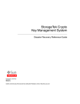
Control Path
HSC
The library is controlled by a Host Software Component (HSC) that resides in the host but
is transparent to the operating system. A separate HSC must reside on each attached host.
The HSC receives requests from the programmatic interface and translates them into
commands which are carried by the control path to the LSM.
The control path consists of the following components:
•
•
•
•
•
Host Software Component
3174, 3274, or compatible controller
Library Management Unit (LMU)
Library Control Unit (LCU)
Library Storage Module (LSM).
SMC
The Storage Management Component (SMC) resides on the MVS host along with the
HSC and communicates with the HSC to:
• influence tape allocation to make sure the correct tape drives are selected and
• intercept mount/dismount and swap messages and translate them to perform tape
hardware functions.
In response to a mount message, the robot in the LSM retrieves the required cartridge
from a storage cell, CAP, or pass-thru port (PTP), and inserts it into an allocated tape
transport. For a dismount, the robot extracts the cartridge from the transport and
returns it to a storage cell, CAP, or PTP in the LSM.
Refer to the NCS Installation Guide and the SMC Configuration and Administration
Guide for more information.
2 MVS/HSC 6.1 Operator’s Guide
Rev. E, 5/31/09 - 312597201
Data Path
The cartridge drives attached to the LSM are part of the cartridge subsystem. The cartridge
subsystem is connected directly to the host forming a data path completely separated from
the control path. This separation means that the data path is still available if a failure
occurs in the control path.
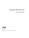
Figure 1 on page 3 illustrates the way an ACS with a single 4410 LSM is divided in terms
of function. Other ACS configurations are treated in this same manner.
ING
AT M
ERYSTE
P
O S
C
HS
4/
3173274
CU
LSM
CD
U
LC
LM
U
LM
U
NOTES:
LSM =
LCU =
LMU =
CD =
CU =
HSC =
3274 =
LIBRARY STORAGE MODULE
LIBRARY CONTROL UNIT
LIBRARY MANGEMENT UNIT
CARTRIDGE DRIVE
CONTROL UNIT
HOST SOFTWARE COMPONENT
TERMINAL CONTROL UNIT (CUSTOMER SUPPLIED)
CD
LEGEND:
LIBRARY CONTROL PATH
(AUTOMATED MOUNTS/DISMOUNTS)
DATA PATH (READ/WRITE)
C27400
Figure 1. Library Control and Data Paths
Chapter 1. General Information 3
Rev. E, 5/31/09 - 312597201
System Components
HSC
The HSC is the overall manager of the library, the interface between the SMC or user
requests and each ACS. The HSC translates mount/dismount requests from SMC into
move requests and routes them to the LMU. The HSC provides information about
volumes in the CDS to allow the SMC to influence allocation.
SMC
The SMC is the interface between the MVSTM operating system and the HSC. The SMC
uses subsystem interfaces and JES3 hooks to:
• influence tape allocation to select a compatible tape device
• intercept MVS mount and dismount messages for library devices.
The SMC also provides the ability to communicate with the user’s tape management
system to generate updates to the HSC tape scratch status.
Library Management Unit
The LMU is the interface between the HSC and the LCU. An LMU emulates a 3278
model 2 terminal and connects to a 3174, 3274, or compatible control unit. The LMU and
attached LCUs are connected with redundant local area networks (LAN 0 and LAN 1).
A single LMU manages from 1 to 24 LSMs. It is capable of receiving mount and dismount
requests from as many as sixteen hosts. When a mount request is received, the LMU
commands the robot in the appropriate LSM to do the following:
1. Move to the location of the cartridge
2. Verify that the cartridge is correct by reading its external Tri-Optic™ label
3. Retrieve the cartridge from the cell location
4. Move it to the proper location
5. Place the cartridge into the specified destination (transport, pass-thru port [PTP] cell,
or CAP cell).
The LSM returns an ending status for each volume move request, which the LMU sends to
the host.
4 MVS/HSC 6.1 Operator’s Guide
Rev. E, 5/31/09 - 312597201
Dual LMU
A dual LMU option is available to minimize control path downtime by allowing an
automatic LMU switch in case of an LMU failure. In this configuration a second LMU is
cabled to the local area network, connecting it to the LSM(s). The HSC directs all work to
one LMU, called the master LMU, while the second LMU, called the standby LMU,
remains powered on as a backup. Designation of master and standby LMU is dynamic and
changes according to environmental conditions.
In a dual LMU configuration:
• both LMUs should be connected to all hosts,
• both LMUs can be powered on at all times, and
• both LMUs must be connected to both LAN 0 and LAN 1.
In the event of a failure in the master LMU, an automatic switch occurs and the standby
LMU becomes the master LMU. The HSC is informed and notifies the operator of the
switch. Outstanding requests are re-driven and all future LMU requests are sent to the new
master LMU. Once the failed LMU is repaired and powered on, it becomes the standby
LMU.
An operator SWitch command is provided for those occasions when it becomes necessary,
or desirable, to dynamically switch to a standby LMU. Except for executing this
command, no manual operator intervention is required. The operator issues the SWitch
command, and the standby LMU takes over as the master LMU after instructing the old
master LMU to initiate IPL. If the old master LMU re-IPLs successfully, it comes up as
the standby LMU.
Note: Warnings and precautions apply to operating in a dual LMU environment. See
“Dual LMU Operational Overview” on page 273 to become familiar with the
requirements.
Station addresses must be specified for both the master and standby LMUs when the HSC
is installed.
Chapter 1. General Information 5
Rev. E, 5/31/09 - 312597201
Library Storage Module
The LSM is a structure that provides storage for tape cartridges. A number of models
interface with the HSC, and each of these models display their own characteristics:
•
•
•
•
•
•
4410 (Standard)
9310 (PowderHorn)
9360 (WolfCreek)
9740 (TimberWolf)
SL3000 (StreamLine)
SL8500 (StreamLine).
For specific information about SL3000 and SL8500 addressing and operations, refer to
“Library Configurations” in the HSC Configuration Guide.
Storage Capacity
In general, the storage capacity of a single LSM ranges from approximately 300 up to
6000 cartridges depending on the type of LSM, the number of cartridge drives (CDs)
attached, and the number of pass-thru ports defined.
Refer to the HSC Configuration Guide for information about LSM storage capacity. See
the appropriate Sun StorageTek hardware operator’s guide for panel definitions for each
model.
Configurations
From zero to four cartridge drive panels can be attached to the exterior of an LSM. Each
drive panel can contain from one to 20 transports. Openings in the walls of the LSM allow
the robot to insert cartridges into the transports.
For all LSMs other than SL3000s and SL8500s libraries, up to 24 LSMs can be
interconnected and cartridges can be passed from one LSM to another through a pass-thru
port (PTP) in the walls of adjacent LSMs.
SL3000 Library
The SL3000 library is comprised of a single LSM for each ACS, with no passthru (PTP)
ports to other libraries. The minimum library configuration is a Base Drive Module
(BDM) with one CAP and up to 24 Drives (in multiples of 8).
Optionally, one Drive Expansion module (DEM) can be added to the left of the BDM,
with one CAP and up to 32 additional drives (in multiples of 8). One to four Cartridge
Expansion Modules (CEMs) can be added left and right of the BDM, with an optional
CAP installed in each CEM. In all cases where the optional CAP and Drives are not
installed, the panel will contain cartridge cells.
On each end of the SL3000 is the Access Expansion Module (AEM), which contains no
cell slots. This module offers a bulk CAP option that allows up to 234 cartridges (18
13-cell magazines) to be entered or ejected.
6 MVS/HSC 6.1 Operator’s Guide
Rev. E, 5/31/09 - 312597201
Dual Robot SL3000 libraries will have a Parking Expansion module (PEM) on each end of
the library. A PEM takes the next available CEM location or replaces an existing CEM on
a fully configured SL3000 Library.
SL8500 Library
The SL8500 library contains four rails on which four handbots travel. Optionally, you can
upgrade to eight handbots, two per rail, for redundancy. The HSC considers each SL8500
rail as a separate LSM.
Refer to “Library Configurations,” in the HSC Configuration Guide for more SL3000 and
SL8500 configuration information.
Cartridge Movement
With the exception of the SL3000 and SL8500 libraries, if a cartridge is in one LSM and
the assigned transport is attached to another LSM, the robot retrieving the cartridge from
its home cell places it into a PTP. The robot in the adjacent LSM retrieves the cartridge
from the PTP and mounts it on the assigned transport, or places it into another PTP to
continue passing the cartridge to the destination LSM.
The SL3000 is a single LSM containing no internal or external PTPs to link multiple
SL3000 libraries together. Refer to “Library Configurations,” in the HSC Configuration
Guide for more information.
The SL8500 contains three internal PTPs (elevators) that move cartridges between LSMs
(rails). External PTPs can be used to link multiple SL8500s. Refer to “Library
Configurations,” in the HSC Configuration Guide for more information.
Each LSM has an access door in the outer wall that allows human access to the interior.
The access door contains a cartridge access port (CAP) that allows cartridges to be entered
and ejected without interrupting automated operations in the LSM.
An attached Library Control Unit (LCU) manages each LSM. When it receives a request
from the LMU, the LCU commands the LSM robot to move to the storage cell, CAP, PTP,
or transport where the cartridge is located, and perform the proper operation (mount,
dismount, or move to/from a cell location, CAP, or PTP).
Mount Process
When an LSM robot mounts a cartridge, it performs the following actions:
1. The servo system moves the robot’s fingers to the center of the cell location.
2. In LSMs other than the SL3000s and SL8500s, a solid-state camera vision system in
the LSM fine-positions the robot’s fingers. The SL3000 and SL8500 Libraries do not
contain a vision system.
3. The camera validates the external Tri-Optic label on the cartridge.
4. The robot retrieves the cartridge from the cell.
5. The robot moves to the specified transport and mounts the cartridge.
Chapter 1. General Information 7
Rev. E, 5/31/09 - 312597201
Dismount Process
When a dismount is requested, the robot removes the cartridge from the transport and does
one of the following:
• returns the cartridge to the source cell if pass-thru operations were not required to
mount the volume
• places the cartridge in an available cell in the robot’s LSM if pass-thru operations
were required to mount the volume. (Normally, pass-thru operations are not
performed to place a cartridge in a storage cell after it has been dismounted, as long
as an available cell exists in the LSM.)
• if specifically directed to return the cartridge to its original home cell location (using
the MNTD Float OFf command), the robot places the cartridge into a PTP cell to
begin passing it back to the original LSM.
Note: Refer to “Controlling Pass-Thru Operations After Dismount” on page 282 for
instructions on using the MNTD Float OFf command.
8 MVS/HSC 6.1 Operator’s Guide
Rev. E, 5/31/09 - 312597201
HSC-to-ACS Operating Modes
The terms ‘‘disconnected mode’’ and ‘‘connected mode’’ refer to the relationship between
the HSC and an ACS. An ACS may be connected to one host while being disconnected
from another. Moreover, a single host may be attached to several ACSs, some of which are
connected to the HSC, and some of which are disconnected from it.
In a functional dual LMU configuration, the ACS can be in a condition referred to as
‘‘standby mode.’’
Connected Mode
An HSC is connected to an ACS when both of the following conditions are true:
• The HSC is executing on that particular host.
• The host and the ACS are communicating with a minimum of one station online to
the ACS (a station is the connection between the host and the Library Management
Unit).
While the HSC is connected to the ACS, messages from the host are intercepted by the
HSC and routed to the ACS which automates the mounts and dismounts.
Disconnected Mode
An HSC is disconnected from an ACS when both of the following conditions are true:
• The HSC is executing on that particular host.
• The host and the ACS are not communicating (no stations are online to the ACS from
that particular host).
In disconnected mode, no automated tape activity can occur for this host using this ACS.
In a multiple-host environment, however, since the ACS is still capable of automated
operations, you can semi-automate mounts and dismounts by issuing HSC commands
from a connected host’s console. As mount/dismount messages are displayed on the
disconnected host’s console, you can issue HSC Mount and DISMount commands from
the connected host’s console to direct the LSM robots to perform the mounts and
dismounts (as long as the cartridges are not selected by the disconnected host).
Chapter 1. General Information 9
Rev. E, 5/31/09 - 312597201
Standby Mode
An HSC is connected to an ACS in standby mode when the following conditions are true:
• The dual LMU feature has been installed.
• No stations are online to the master LMU.
• At least one station is online to the standby LMU.
In standby mode, the HSC intercepts mount and dismount messages and accepts operator
cartridge movement commands. The HSC cannot send requests to the master LMU,
however, since no stations are online. The operator can resolve this situation by issuing the
HSC SWitch command causing the standby LMU to become the master LMU. When the
standby LMU has assumed master LMU functionality, the HSC sends all pending (or
saved) LMU requests to the new master LMU.
10 MVS/HSC 6.1 Operator’s Guide
Rev. E, 5/31/09 - 312597201
LSM Operating Modes
An LSM operating mode is the way in which an LSM and all the HSCs attached to it
interact. The two operating modes are automatic and manual. Automatic mode is the
normal operating mode of an LSM. An LSM is either in automatic mode to all hosts or in
manual mode to all hosts.
Automatic Mode
An LSM operating in automatic mode does not require operator intervention for
mounting, dismounting, swapping, or pass-thru cartridge movement. When the LSM is in
automatic mode, the operator can use console commands or HSC batch utility processing
to enter or eject cartridges through the CAP.
Manual Mode
An LSM operating in manual mode cannot perform any automated operations. The
operator must intervene and perform all mounts and dismounts manually.
Caution: Sun StorageTek strongly recommends that you do not place SL3000
and SL8500 libraries in manual mode. To use manual mode, all LSMs in the
SL3000 and SL8500 must be offline, and that means all CAPs and drives are
unavailable for automated operations. Additionally, SL3000 and SL8500 LSMs have
been designed for high cartridge density, so there is limited room for manually
mounting and dismounting cartridges.
Refer to the “Precautions” topic in the SL3000 or SL8500 Modular Library System
User’s Guide for safety requirements and physical restrictions if you decide that you
must enter the library.
Chapter 1. General Information 11
Rev. E, 5/31/09 - 312597201
12 MVS/HSC 6.1 Operator’s Guide
Rev. E, 5/31/09 - 312597201
Chapter 2. Commands, Control Statements, and Utilities
Overview
HSC operator commands and library utilities allow an operator to allocate, display the
status of, and manage library resources.
This chapter discusses operator commands in detail and gives a brief overview of library
utilities. The following topics are discussed:
•
•
•
•
•
•
overview of command syntax
HSC commands and control statements
SCP commands
GCS command
CMS commands
library utilities overview.
The HSC subsystem must be operational before most of these commands and utilities can
be executed.
Notes:
• For a detailed description of library utilities, refer to the HSC System Programmer’s
Guide.
• HSC messages and codes are described in detail in the HSC Messages and Codes
Manual.
Virtual Storage Manager (VSM) Support
VSM support has been added for certain HSC operator commands. See the VTCS
documentation for more information.
Chapter 2. Commands, Control Statements, and Utilities 13
Rev. E, 5/31/09 - 312597201
Overview of Command Syntax
This section contains operator command rules and conventions used in this chapter to
describe command syntax.
Operator Command Syntax Rules
An HSC operator command consists of a command prefix character (optional), a
command name, and zero or more positional parameters and keyword parameters. Rules
governing these commands are listed below.
• The optional command prefix character identifies which subsystem processes the
command. The systems programmer defines this prefix character (for example, “.,”
“#,” “@”) during the LIBGEN process.
- If a prefix character is used, the command must appear immediately following
(concatenated to) the prefix character.
- A null character can be specified as the command prefix character. When the
command prefix is a null character, you must use the MVS MODIFY command
to state commands to the HSC. The following formats for the MVS MODIFY
command may be used:
MODIFY subsystemname,hsccommand
or
F subsystemname,hsccommand
where:
subsystem-name
is the entry in the subsystem name table for the HSC. This one- to
four-character HSC subsystem name is specified by a systems
programmer by adding an element to the IEFSSNxx entry in the
SYS1.PARMLIB (e.g., SLS0).
hsc-command
is any valid HSC command and zero or more parameters.
Examples of how a specific HSC command can be issued are:
MODIFY SLS0,MOUNT 123456 B04
or
F SLS0,MOUNT 123456 B04
Note: The examples shown in this chapter do not show the use of either a command
prefix character or the MVS MODIFY command. Use of a prefix character is
illustrated in the examples found in other chapters in this manual.
14 MVS/HSC 6.1 Operator’s Guide
Rev. E, 5/31/09 - 312597201
• Keyword parameters that require or allow a user-supplied value can be specified in
either of following formats:
- Enclosing the user-supplied value(s) in parentheses and concatenating it to the
keyword. For example,
HOSTID(hostid)
- Concatenating the user-supplied value(s) to the keyword with an equal sign. For
example,
HOSTID=hostid
Notes:
• Both keyword syntax formats are illustrated in this manual.
• Unless otherwise specified, a list of user-supplied values must be enclosed in
parentheses. Refer to “Ranges and Lists” on page 25 for more information
about specifying lists.
• Except as noted, parameters can be separated by a comma or a blank. Consecutive
blanks following either of these delimiters are ignored.
• Commands and parameters can be entered in any combination of uppercase and
lowercase letters.
• Command replies are always sent to the issuing console and, in some cases such as
mounts and dismounts, are routed to other consoles such as the tape library console
and tape pool console.
Chapter 2. Commands, Control Statements, and Utilities 15
Rev. E, 5/31/09 - 312597201
Syntax Flow Diagrams
Syntax is illustrated using flow diagrams. These can include the following elements:
• syntax — the diagram itself.
• items — individual elements inside the diagram. Items can be keywords, variables,
delimiters, operators, fragment references, and separators.
• groups — a collection of items or other groups.
The following sections describe syntax flow diagram features and include some generic
examples.
Specifying Commands
Commands are composed of command names, keyword parameters, and positional
parameters. Command names initiate command execution, keyword parameters are
operands that contain keywords and their related values, and positional parameters are
operands that are identified by their position in the command string rather than by
keywords.
• Keyword parameters can be specified in any order. The HSC accepts (tolerates)
multiple occurrences of a keyword. The value assigned to a keyword reflects the last
occurrence of a keyword within a command.
• Positional parameters must be entered in the order shown in the syntax diagram.
• Uppercase letters indicate the minimum abbreviation for the command name,
keyword, or positional parameter.
Variables
Variables are italicized.
Delimiters
If a comma(,), a semicolon(;), or other delimiter is shown with an element of the syntax
diagram, it must be entered as part of the statement or command.
16 MVS/HSC 6.1 Operator’s Guide
Rev. E, 5/31/09 - 312597201
Flow Lines
Syntax diagrams consist of horizontal and vertical lines and the text of a command,
control statement, macro, or utility.
COMMAND/MACRO/UTILITY
or
Item1
Item2
Item3
Diagrams are read left to right and top to bottom. Arrows indicate flow and direction.
• a statement begins with
• a statement ends with
• diagrams continuing to the next line begin with
• fragments begin and end with |
COMMAND/UTILITY NAME
Item1(variable1)
Item2(
variable2
)
variable3
variable4
Item3(variable5)
Chapter 2. Commands, Control Statements, and Utilities 17
Rev. E, 5/31/09 - 312597201
Single Required Choice
Branch lines, without repeat arrows, indicate that a single choice must be made. If one of
the items from which a choice is being made is on the base line of the diagram, a single
choice is required.
Item1
Item2
Item3
Single Optional Choice
If the first item is on the line below the base line, a single choice of items in the stack is
optional.
Item1
Item2
Item3
Defaults
Default values and parameters appear above the syntax diagram line. In the following
example, if a value is not specified with the command, Default Value is used by the HSC.
Default Value
Value2
Value3
Some keyword parameters provide a choice of values in a stack. When the stack contains a
default value, the keyword and the value choices are placed below the baseline to indicate
that they are optional, and the default value appears above the keyword line. In the
following example, if the keyword is not specified with the command,
Keyword(Default Value) is used by the HSC.
Default Value
Keyword
Value2
Value3
18 MVS/HSC 6.1 Operator’s Guide
Rev. E, 5/31/09 - 312597201
Repeat Symbol
A repeat symbol indicates that more than one choice can be made or that a single choice
can be made more than once. The repeat symbol shown in this example indicates that a
comma is required as the repeat separator.
,
variable
Syntax Continuation (Fragments)
Fragment references direct you to parts (fragments) of the syntax that contain more detail
than can be shown in the main syntax diagram.
COMMAND/UTILITY NAME
Fragment Reference
Fragment:
Item1(
variable1
,
variable2
Item2(
variable5
variable3
)
variable4
,
variable6
variable7
)
variable8
How to Read Syntax Flow Diagrams
To read command syntax, start at the double arrowheads (
the right adding syntax elements as you go.
) on the left and move to
• At line intersections, choose a path to take.
• Continue following the chosen path to the right (do not backtrack).
• Any element you cannot bypass is required.
• Any element shown above the line is a default.
• Any element shown below the line that you can bypass is an option.
• The diagram ends at the two arrowheads facing each other (
).
The syntax for some commands is too large to fit on one line. These diagrams are split,
which is indicated by ending the unfinished line and beginning the next line with a single
arrowhead (
).
Chapter 2. Commands, Control Statements, and Utilities 19
Rev. E, 5/31/09 - 312597201
Syntax Flow Diagram Example
Consider the syntax flow diagram for the Mount command.
Syntax Flow Diagram Example (Mount Command)
Mount
volser
devaddr
,
host-id
SCRTCH
PRIVAT
Readonly
devaddr
host-id
SUBpool (subpool-name)
To read the syntax flow diagram for the Mount command:
• Start at (
) and follow the line to the right to the word Mount. Mount cannot be
bypassed so it is required: it can be abbreviated to “M.”
• Continuing to the right there is a split, indicating a choice. You must choose either
volser, SCRTCH, or PRIVAT.
• Continuing along either path, the required variable devaddr cannot be bypassed and
is required. Substitute a device address for devaddr.
• Continuing along either path again, the following optional choice is presented:
• Bypass the choice and go straight to (
); no other coding is necessary.
• Include any of the following parameter combinations:
• host-id and nothing else, or
• host-id and either Readonly or Subpool(subpool-name), or
• a comma and Readonly, or
• Subpool(subpool-name).
The following are all valid ways to issue a Mount command for a specific VOLSER:
MOUNT
MOUNT
MOUNT
MOUNT
volser
volser
volser
volser
20 MVS/HSC 6.1 Operator’s Guide
Rev. E, 5/31/09 - 312597201
devaddr
devaddr hostid
devaddr hostid READONLY
devaddr,,READONLY
Library Identification
Each ACS, LSM, and CAP is assigned a unique identification number during LIBGEN.
Use this number in HSC commands and utilities when identifying a specific ACSid,
LSMid, or CAPid.
• ACSid (acs-id) is a hexadecimal value from 00 through FF that identifies the LMU.
An acs-id is the result of defining the SLIALIST macro during a LIBGEN. See the
HSC Configuration Guide for information about the SLIALIST macro. The first
ACS listed in this macro acquires a hexadecimal identifier of 00, the second ACS
listed acquires a hexadecimal identifier of 01, and so forth until all ACSs are
identified.
• An LSM number (ll) is a hexadecimal value from 00 through 17. It differentiates an
LSM from every other LSM connected to the same LMU.
An LSM number is the result of defining the SLIACS macro LSM parameter. See the
HSC Configuration Guide for information about the SLIACS macro. The first LSM
listed for an ACS acquires a hexadecimal number of 00, the second LSM listed for an
ACS acquires a hexadecimal number of 01, and so forth.
• An LSMid (lsm-id) is made up of the ACSid and the LSM number separated by a
colon (:). It differentiates an LSM from every other LSM in a library.
• A CAP number is a hexadecimal value from 00 to 02 for all existing libraries, except
for SL3000 libraries. The CAP number for an SL3000 is a hexadecimal value from
00 to 0B. The CAP number identifies a specific CAP in an LSM that has more than
one CAP.
• A CAPid (cap-id) is a hexadecimal value made up of the LSMid and the CAP
number separated by a colon. Refer to “How to Specify a CAPid” on page 22 for
additional information, including a description of CAPid formats.
Some HSC commands and utilities require, or optionally allow, the user to specify a host
identifier or a VOLSER.
• The host-id for a given host is the identifier specified in the HOSTID parameter of
the SLILIBRY macro in the LIBGEN. The HOSTID parameter is the SMF system
identifier for both JES2 and JES3. Valid characters for a HOSTID are A-Z, 0-9, #
(crosshatch), $, and @.
• A VOLSER (volser) identifies a volume serial number consisting of one to six
characters. Valid characters are A-Z, 0-9, #, $, ¥ (yen character), and optional trailing
blanks. Leading blanks are not allowed.
Chapter 2. Commands, Control Statements, and Utilities 21
Rev. E, 5/31/09 - 312597201
How to Specify a CAPid
A CAPid specifies a particular CAP in the library. Each CAP is identified by the LSMid of
the LSM that the CAP is attached to and a CAP number to distinguish it from other CAPs
in that LSM.
CAP configurations differ based on the LSM type. The following configurations are
available:
LSM (Model 4410) and PowderHorn LSM (Model 9310)
This LSM is configured with either the standard 21-cell CAP or an enhanced CAP.
An enhanced CAP contains two 40-cell magazine-style CAPs and a one-cell priority
CAP (PCAP). The 40-cell CAPs function independently.
WolfCreek LSM (Models 9360-050, 9360-075, and 9360-100)
This LSM is configured with a WolfCreek CAP which contains a 20-cell
magazine-style CAP and a PCAP. An optional 30-cell, magazine-style CAP, called a
WolfCreek optional CAP, may be added to the WolfCreek CAP.
TimberWolf LSM (Model 9740)
This LSM is configured with either a 14-cell permanent rack or a 10-cell removable
magazine.
StreamLine Library (Model SL3000)
The library is configured with 2, 13-cell removable magazines in each CAP. This
library can contain up to 12 CAPs (00-0B).
StreamLine Library (Model SL8500)
This library is configured with 3, 13-cell removable magazines. An optional 39-cell
CAP can be added.
CAPid Formats
Two formats can be used to specify a CAPid:
• AA:LL, where AA is the ACSid (hexadecimal 00 through FF) and LL is the LSM
number (hexadecimal 00 through 17). This format is referred to as the lsm-id.
• AA:LL:CC, where AA:LL is the LSMid and :CC is the CAP number. This format is
referred to as the cap-id.
Caution: Do not use a colon as the MVS command delimiter because the system will
process the colon in the new CAPid format as the end of the command. All information
following the colon in an HSC command will not be processed.
The appropriate format to use is determined by the CAP hardware and the command being
specified.
• The AA:LL format can be specified to allow the HSC to select a CAP based on CAP
preference.
22 MVS/HSC 6.1 Operator’s Guide
Rev. E, 5/31/09 - 312597201
• The AA:LL:CC format can be specified for any CAP hardware in any command that
accepts a CAPid. This is the preferred format. Valid CAP numbers are:
00 indicates one of the following:
•
•
•
•
•
•
a 21-cell 4410 or 9310 standard CAP
the right-hand 40-cell 4410 or 9310 enhanced CAP
the 20-cell 9360 WolfCreek CAP
a 14-cell or 10-cell removable magazine 9740 TimberWolf CAP
a left-side SL3000 AEM CAP, consisting of 18, 13-cell removable magazines
the left-hand 39-cell SL8500 library CAP.
Note: The LSM portion of the SL8500 CAP must be the LSM number of the
LSM on track 1 of the structure.
01 indicates one of the following:
•
•
•
•
the left-hand 40-cell 4410 or 9310 enhanced CAP
the 30-cell 9360 WolfCreek optional CAP
an optional SL3000 CEM CAP consisting of 2, 13-cell removable magazines
the right-hand optional 39-cell SL8500 library CAP.
02 indicates one of the following:
• PCAP in either a 4410 or 9310 enhanced CAP or a 9360 WolfCreek CAP.
• an optional SL3000 CEM CAP consisting of 2, 13-cell removable magazines.
03, 04, 05 indicates the following:
• an optional SL3000 CEM/DEM CAPs each consisting of 2, 13-cell removable
magazines.
06 indicates the following:
• the only required SL3000 BDM CAP consisting of 2, 13-cell removable
magazines.
07, 08, 09, 0A indicates the following:
• an optional SL3000 CEM CAPs each consisting of 2, 13-cell removable
magazines.
0B indicates the following:
• a right-side SL3000 AEM CAP, consisting of 18, 13-cell removable magazines
Chapter 2. Commands, Control Statements, and Utilities 23
Rev. E, 5/31/09 - 312597201
Notes:
• If SL3000 library CAPs are not present, the HSC reports them as “not installed”
This keeps CAP addresses from changing as new CAPs are added.
• Refer to the individual command explanations for additional information on
specifying CAPids.
• SL3000 and SL8500 libraries do not contain a PCAP.
24 MVS/HSC 6.1 Operator’s Guide
Rev. E, 5/31/09 - 312597201
Ranges and Lists
HSC commands and utilities often allow the user to specify ranges and lists of elements.
1. An inclusive range is indicated by a pair of elements of the same length and data
type, joined by a dash. The first element must be strictly less than the second
element.
• A hexadecimal range consists of a pair of hexadecimal numbers (for example,
0A2-0AD, or 000-0FC).
• A decimal range consists of a pair of decimal numbers (for example, 1-9, or
010-094). Leading zeros are not required.
• A numeric VOLSER range (vol-range) consists of a pair of VOLSER elements
containing a decimal numeric portion of 1 to 6 digits (for example,
ABC012-ABC025, or X123CB-X277CB). The decimal portion is referred to as
an incremental range. The following additional restrictions apply:
- The character positions of the incremental portion of both range elements
must match.
- The non-incremental characters of the first element must be identical to
those of the second element.
- You cannot increment two portions of a range element. If 111AAA is the
first element, you cannot specify 112AAB for the second element.
- If a VOLSER range contains more than one decimal portion, any portion
is valid as the incremental range. For example:
A00B00
the largest range that can be specified is A00B00
through A99B99.
A0B0CC
the largest range that can be specified is A0B0CC
through A9B9CC.
000XXX
the largest range that can be specified is 000XXX
through 999XXX.
Note: A VOLSER range for most operator commands is limited to 100
entries. If a larger range is entered, only the first 100 VOLSERs in the
range are acted on. If HSC utilities are used, the entire range is processed.
• An alphabetic VOLSER range (vol-range) consists of a pair of VOLSER
elements containing an incremental portion of 1 to 6 characters (for example,
000AAA-000ZZZ, or 9AAA55-9ZZZ55). This portion is referred to as an
incremental range. The following additional restrictions apply:
- The character positions of the incremental portion of both range elements
must match.
- The non-incremental characters of the first element must be identical to
those of the second element.
Chapter 2. Commands, Control Statements, and Utilities 25
Rev. E, 5/31/09 - 312597201
- You cannot increment two portions of a range element. If 111AAA is the
first element, you cannot specify 112AAB for the second element.
- The alphabetic portion of the VOLSER range is defined as being from
character A to Z. To increment multi-character sequences, each character
increments to Z. For instance, ACZ is part of the AAA-AMM range.
Examples are:
A00A0-A99A0
increments VOLSERs A00A0 through A09A0,
then A10A0 through A99A0.
9AA9A-9ZZ9A
increments VOLSERs 9AA9A through 9AZ9A,
then 9BA9A through 9ZZ9A.
111AAA-111ZZZ
increments VOLSERs 111AAA through
111AAZ, then 111ABA through 111ZZZ.
999AM8- 999CM8
increments VOLSERs 999AM8 through
999AZ8, then 999BA8 through 999CM8
A3BZZ9- A3CDE9 increments VOLSERs A3BZZ9 through
A3CAA9, then A3CAB9 through A3CDE9
AAAAAAAAACCC
increments VOLSERs AAAAAA through
AAAAAZ, then AAAABA through AAACCC
CCCNNNDDDNNN
increments VOLSERs CCCNNN through
CCCNNZ, then CCCNOA through DDDNNN*
* Caution: This is a very large range.
The number of volumes in an alphabetic VOLSER range depends on the
number of elements in the incrementing portion of the VOLSER range. For an
A to Z range in each character position, the number of volumes can be
calculated by 26 to the power of the number of positions that are being
incremented.
A-Z
261
26
AA-ZZ
262
676
AAA-ZZZ
263
17,576
AAAA-ZZZZ
264
456,976
AAAAA-ZZZZZ
265
11,881,376
AAAAAA-ZZZZZZ
266
308,915,776
Note: For most operator commands, a VOLSER range is limited to 100 entries.
If a large range is entered, only the first 100 VOLSERs are acted upon. If HSC
utilities are used, the entire range is processed.
26 MVS/HSC 6.1 Operator’s Guide
Rev. E, 5/31/09 - 312597201
2. A list consists of one or more elements. If more than one element is specified, the
elements must be separated by a comma or a blank, and the entire list enclosed in
parentheses.
• For some HSC operator commands, an element may consist of a single item or a
range. Refer to the individual command explanations for valid list entries.
• In general, HSC utilities do not allow ranges to be specified in a list. The
exception to this is a VOLSER list (vol-list), which does allow ranges to be
specified.
For VOLATTR control statements, you can use wildcard characters (%, ?, or *)
to identify a list of VOLSERs.
Table 1 on page 28 gives an overview of the symbols used to designate portions of a
library in commands.
Chapter 2. Commands, Control Statements, and Utilities 27
Rev. E, 5/31/09 - 312597201
Table 1. Library Identifiers
Library Identifier
Command Syntax
Input Format
Description
ACS Identifier (ACSid)
acs-id
AA
Hexadecimal value (00-FF);
identifies the selected LMU.
ACSid Range
acs-range
AA1 -AA2
Two ACSids joined by a dash,
where aa1 < aa2 .
ACSid List
acs-list
(AA1 ,AA2 - AA3 , AA4 ,...,AAn )
List of ACSids and/or ACSid
ranges in any combination,
enclosed in parentheses.
LSM Number
ll
LL
Hexadecimal value (00-17);
differentiates an LSM from other
LSMs in an ACS.
LSM Identifier (LSMid)
lsm-id
AA:LL
Differentiates an LSM from other
LSMs in a library.
LSMid Range
lsm-range
AA:LL1 -AA:LL2
Two LSMids joined by a dash,
where AA:LL1 < AA:LL2 .
LSMid List
lsm-list
(AA:LL1 ,AA:LL2 - AA:LL3 ,
AA:LL4 ,...,AA:LLn )
List of LSMids and/or LSMid
ranges in any combination,
enclosed in parentheses.
CAP Identifier (CAPid)
cap-id or lsm-id
AA:LL:CC or AA:LL
Identifies a specific CAP, where
AA:LL is the LSMid and CC is
the CAP number. Valid CAP
numbers are 00 through 0B.
Note: An lsm-id can be used to
allow the HSC to select a CAP in
a particular LSM based on CAP
preference.
CAPid Range
cap-range
AA:LL1 -AA:LL2 or
AA:LL:CC1 -AA:LL:CC 2
Two CAPids joined by a dash,
where AA:LL1 < AA:LL2 , or CC1
< CC2 .
CAPid List
cap-list
(AA:LL:CC1 ,
AA:LL:CC2 -AA:LL:CC3 ,
AA:LL:CC4 ,...,AA:LL:Cn )
List of CAPids and/or CAPid
ranges in any combination,
enclosed in parentheses. The
abbreviated CAPid format may
be used for some HSC
commands.
VOLSER
volser
VVVVVV
Single volume serial number.
VOLSER range
vol-range
VVVXXX-VVVYYY or
VVVVVX-VVVVVY or
XVVVVV-YVVVVV or ....
Two volume serial numbers
joined by a dash. The incremental
portions must be in the same
character positions.
28 MVS/HSC 6.1 Operator’s Guide
Rev. E, 5/31/09 - 312597201
Table 1. Library Identifiers
Library Identifier
VOLSER list
Command Syntax
vol-list
Input Format
(VVVAAA, VVVBBB,
VVCCVV-VVDDVV,
...,
XXXVVV-YYYVVV, VZZZVV,
...)
Description
List of one or more VOLSERs
and/or VOLSER ranges in any
combination, enclosed in
parentheses.
Chapter 2. Commands, Control Statements, and Utilities 29
Rev. E, 5/31/09 - 312597201
HSC Commands and Control Statements
HSC operator commands and control statements provide status information about the
library, and allow an operator to control volume movement within the library and change
the status of library resources.
HSC Commands
Command syntax and parameter explanations are provided for each of the following HSC
operator commands:
• ALLOC
• Journal
• SRVlev
• CAPPref
• MNTD
• STOPMN (PM)
• CDs
• MODify (F)
• SWitch
• CLean
• MONITOR (MN)
• TRace
• COMMPath
• Mount
• TRACELKP
• DISMount
• MOVe
• UEXIT
• Display
• OPTion
• Vary
• DRAin
• RECover
• VIew
• EJect
• RELease
• Warn
• ENter
• SENter
30 MVS/HSC 6.1 Operator’s Guide
Rev. E, 5/31/09 - 312597201
Control Statements
Certain HSC commands can also be used as PARMLIB control statements which are
executed at HSC initialization. PARMLIB control statements enable you to tailor HSC
startup options to the requirements of your data center. Unless otherwise specified, the
options defined in a control statement can be dynamically changed during normal
operations by issuing the corresponding HSC operator command.
Refer to the HSC System Programmer’s Guide for more information about PARMLIB
control statements.
HSC Service Levels
The HSC subsystem can operate at either of two service levels:
• base service level
• full service level.
Normally the HSC initializes to the full service level when started. The HSC can be started
at the base service level, however, and then brought to the full service level at any time by
issuing the SRVlev FULL command. Refer to “SRVlev (Service Level) Command” on
page 211 for details on command syntax and parameters.
Base Service Level Functions
The base service level is the nucleus of the HSC subsystem. It provides the functions
necessary to execute as an extension of the operating system, and satisfies the
requirements defined by the operating environment in place at the time of execution.
All operator commands can be issued with the HSC executing at the base service level.
Commands that involve library hardware, however, cannot perform their function
completely.
Mount Requests Intercepted During Base Service Level Operations
Mount messages intercepted by the SMC while the HSC is operating at the base service
level are not sent to the HSC, but are left pending until the HSC reaches the full service
level.
When the SMC recognizes that the HSC has reached the full service level, the mounts are
redriven. These mount messages that occur with SMC intervention, and that are
subsequently redriven when the HSC reaches the full service level, have their subpool
specification honored.
Pending Mount Request During Base Service Level Operations
Mount requests for transports attached to the ACS are left pending whenever the HSC is
operating at the base service level. When the HSC is brought up to the full service level,
all outstanding mount requests are processed and the mounts performed.
Chapter 2. Commands, Control Statements, and Utilities 31
Rev. E, 5/31/09 - 312597201
Full Service Level Functions
The full service level of operation for the HSC provides all of the functions available and
necessary to invoke and sustain complete library operations. These functions include:
•
•
•
•
•
•
•
•
mount/dismount processing
CAP processing
cartridge and cell inventory management
LMU access
library resource recovery
support for all library utilities
support for all HSC commands
support for programmatic interface.
Table 2 identifies the HSC commands that can execute at both the base and full service
levels, and those that can execute only at the full service level.
Table 2. HSC Command Execution at Base and Full Service Levels
Command
Service Level
Execution
Base
Full
ALLOC
YES
YES
CAPPref
NO
YES
CDs
YES
YES
CLean
NO
YES
COMMPath
YES
YES
DISMount
NO
YES
Display
YES
YES
DRAin
NO
YES
EJect
NO
YES
ENter
NO
YES
Journal
YES
YES
MNTD
NO
YES
MODify (F)
NO
YES
MONITOR (MN)
YES
YES
Mount
NO
YES
MOVe
NO
YES
OPTion
YES
YES
RECover
NO
YES
32 MVS/HSC 6.1 Operator’s Guide
Rev. E, 5/31/09 - 312597201
Table 2. HSC Command Execution at Base and Full Service Levels (Continued)
Command
Service Level
Execution
Base
Full
RELease
NO
YES
SENter
NO
YES
SRVIew
YES
YES
STOPMN (PM)
YES
YES
SWitch
NO
YES
TRace
YES
YES
TRACELKP
YES
YES
UEXIT
YES
YES
Vary
NO
YES
VIew
NO
YES
Warn
NO
YES
Chapter 2. Commands, Control Statements, and Utilities 33
Rev. E, 5/31/09 - 312597201
ALLOC
Allocation (ALLOC) Command and Control Statement
The ALLOC command and control statement is used to set or change HSC allocation
options. This allows you to customize device allocation to your environment, reduce the
need for operator intervention, and improve the overall performance of the library.
Note: Allocation functions are performed by the Storage Management Component
(SMC). Except as noted below, parameters set by this command are honored by the SMC.
Refer to the SMC Configuration and Administration Guide for information about SMC
functionality.
The following allocation options can be set or changed using this command:
• scratch preferencing technique to designate LSMs with low or zero scratch counts as
least-preferenced
• scratch preferencing technique for libraries with mixed LSM types
• scratch preferencing technique for libraries with multiple LSMs
The ALLOC command must be issued before a job is submitted to have an effect on
device allocation. The specified options remain in effect for a designated host until they
are changed again by another ALLOC command, or until the HSC is shutdown and
restarted. Specify the ALLOC command in PARMLIB to make sure the allocation options
remain in effect when the HSC is restarted.
Note: Use the HSC Display ALLOC command to list the HSC allocation options that are
currently in effect. Refer to “Display ALLOC” on page 67 for details on command syntax
and parameters.
34 MVS/HSC 6.1 Operator’s Guide
Rev. E, 5/31/09 - 312597201
ALLOC
Syntax
,
ALLOC
LOWscr(
NONE
)
HOSTID(host-id)
ANY
LSMpref(
NONE
4410
)
9310
9360
SCRtech(
COUNT
ROTATE
)
Command Name
ALLOC
initiates the ALLOC command. One or more keyword parameters must be specified
with each command.
Parameters
LOWscr
indicates whether or not LSMs with low or zero scratch counts are to be
least-preferenced.
Caution: Using different settings of LOWscr from host to host is not recommended.
If a difference exists, unusually fast depletion of scratch volumes from certain
LSMs may result, leading to increased pass-thru activity, reduced robotics
utilization, and reduced library throughput.
HSC User Exit 02 can be used to override the LOWscr parameter on a case by case
basis; however, it cannot be used to override the LOWscr and LSMpref parameters
simultaneously.
NONE
specifies that least-preferencing is not in effect. If the current scratch count for
an LSM is below the scratch threshold level defined, or if no scratch threshold
exists and the current scratch count is zero, the LSM continues to be
preferenced according to the LSMpref and SCRtech values in effect. NONE is
the initial value for the HSC.
Chapter 2. Commands, Control Statements, and Utilities 35
Rev. E, 5/31/09 - 312597201
ALLOC
ANY
specifies that any LSM can be least-preferenced if either of the following
conditions is met:
• A scratch threshold level is defined for the LSM and its scratch count is
below this threshold.
• No scratch threshold exists for the LSM and its scratch count is zero.
A least-preferenced LSM does not participate in the rotation algorithm and may
be any LSM type, including the type specified in the LSMpref parameter.
Online and unallocated transports in least-preferenced LSMs are still eligible to
satisfy allocation requests.
Note: If least-preferencing is desired for an LSM with a low but nonzero
scratch count, the Warn command must be used to set a scratch threshold for the
LSM. (Refer to “WARN Command” on page 238 for details on syntax and
parameters.) It is not necessary to set a scratch threshold of zero. Scratch
thresholds for ACSs are not relevant and have no effect on least-preferencing
LSMs.
LSMpref
indicates if a particular type of LSM is preferenced over all other LSM types to
satisfy scratch requests. Only one type of LSM can be preferenced at a time.
Note: 9740, SL3000, and SL8500 LSMs do not participate in LSM preferencing.
Caution: Using different settings of LSMpref from host to host is not recommended.
If a difference exists, unusually fast depletion of scratch volumes from certain
LSMs may result, leading to increased pass-thru activity, reduced robotics
utilization, and reduced library throughput.
When a particular type of LSM is preferenced over all other LSM types, two logical
groupings of LSMs are created: one composed of all LSMs of the preferenced type,
and one composed of all other LSMs of non-preferenced types. LSMs within the
non-preferenced group are treated as though they are the same type.
HSC User Exits 02 and 04 can be used to override the LSMpref parameter on a case
by case basis.
NONE
indicates that all LSMs are logically grouped together and treated as though
they are the same type. No preferencing by LSM type is performed. NONE is
the initial value for the HSC.
4410
indicates that the 4410 LSMs are to be preferred over all non-4410 LSMs.
9310
indicates that the 9310 LSMs are to be preferred over all non-9310 LSMs.
36 MVS/HSC 6.1 Operator’s Guide
Rev. E, 5/31/09 - 312597201
ALLOC
9360
indicates that the 9360 LSMs are to be preferred over all non-9360 LSMs.
SCRtech
indicates how LSMs are individually preferenced to satisfy scratch requests.
Caution: Using different settings of SCRtech from host to host is not recommended.
If a difference exists, unusually fast depletion of scratch volumes from certain
LSMs may result, leading to increased pass-thru activity, reduced robotics
utilization, and reduced library throughput.
COUNT
specifies that LSMs are individually preferenced in descending scratch count
order. COUNT is the initial value for the HSC.
ROTATE
specifies that LSMs are individually preferenced using a rotation algorithm.
Each successive scratch request is preferenced to the next LSM. Once all LSMs
have been preferenced, the rotation starts over. The starting sequence of LSMs
is in descending scratch count order.
HOSTID
identifies the host associated with the allocation options being specified in the
command. If this parameter is not specified, the changes affect the host from which
the command is issued.
host-id
is the host ID (the SMF system identifier for both JES2 and JES3).
Usage Considerations
User exits can be invoked to override the ALLOC settings for Defer, LOWscr and
LSMpref. Refer to the NCS User Exit Guide for information.
Example
The following example illustrates the use of the ALLOC command and control statement.
Specifying Multiple Allocation Options:
ALLOC LOWSCR(ANY),LSMPREF(9310),SCRTECH(ROTATE)
Whenever the number of scratch cartridges in an LSM drops below the defined scratch
threshold, LOWSCR(ANY) directs the HSC to least-preference that LSM.
LSMPREF(9310) directs the HSC to place all 9310 LSMs into one group and all other
LSMs (both 4410 and 9360) into another group. The HSC prefers all scratch requests to
the group of 9310 LSMs. In an environment that has a large number of scratch mounts, the
9310 LSMs are faster than the 4410 LSMs and can hold more scratch cartridges than the
9360 LSMs.
Chapter 2. Commands, Control Statements, and Utilities 37
Rev. E, 5/31/09 - 312597201
ALLOC
SCRTECH(ROTATE) directs the HSC to rotate the scratch requests among the 9310
LSMs in descending scratch count order. That is, the first scratch request is directed to the
9310 LSM with the most scratch cartridges, the second request is directed to the 9310
LSM with the second highest number of scratch cartridges, and so forth. When a scratch
request has been directed to each of the 9310 LSMs, the rotation starts over.
The rotation algorithm applies separately to each group of preferred and non-preferred
LSMs. If all transports in all 9310 LSMs are offline or already allocated, the scratch
request workload is distributed across all non-9310 LSMs in the library complex.
Note: Refer to “LSM Scratch Preferencing” on page 286 for more information and
examples.
38 MVS/HSC 6.1 Operator’s Guide
Rev. E, 5/31/09 - 312597201
CAPPref
CAP Preference (CAPPref) Command and Control Statement
The CAPPref command and control statement is used for the following:
• assign a preference value to one or more designated Cartridge Access Ports (CAPs)
in the ACS.
• place a CAP into automatic or manual mode.
Each LSM may contain one or more CAPs which allow you to enter and eject cartridges
without interrupting automated operations. Several HSC commands and utilities require
the use of a CAP and give you the option to either specify the CAP you want to use or
allow the HSC to automatically select which CAP to use. When you allow the HSC to
make the selection, a CAP is chosen based on availability and CAP preference value.
Assigning CAP preference values establishes an ordered list of CAPs from which the HSC
selects an available CAP with the highest nonzero preference value.
A CAP’s preference value is zero until it is changed by a CAPPref command. Zero
preference CAPs are never automatically selected by the HSC; however, they can be
explicitly requested by the user
CAPPref can be issued as an operator command or specified in PARMLIB. Refer to
“PARMLIB Control Statements” in the HSC System Programmer’s Guide for information
about PARMLIB.
• A CAP preference value is only in effect on the host that executes the command.
• CAP mode (automatic or manual) is in effect on all hosts system-wide for each CAP;
it cannot be set discretely for each host.
CAPPref Considerations
CAP preference values are retained in the control data set from one HSC start to another.
• If the CAPPref command is contained in PARMLIB, do not code the AUTO or
MANual setting. If these settings are used and the CAP is already in the selected
mode, the command is rejected without changing the preference value.
• If the CAPPref command is contained in PARMLIB when the HSC is brought up,
and the command can be executed by the host being started:
• Each CAP is assigned the preference value that is specified in PARMLIB.
• Each CAP is placed in the mode that is specified in PARMLIB. This affects all
hosts in the system.
• If the CAPPref command is not contained in PARMLIB when the HSC is brought up,
or the command cannot be executed by the host being started:
• Each CAP is assigned the preference value that was last recorded for it in the
control data set.
• Each CAP is placed into the state that was last recorded for it in the control data
set.
Chapter 2. Commands, Control Statements, and Utilities 39
Rev. E, 5/31/09 - 312597201
CAPPref
Syntax
CAPPref
prefvlue
lsm-id
cap-id
host-id
cap-range
,
(
cap-list
AUTO
MANual
)
Command Name
CAPPref
initiates the CAP preference command or control statement.
Parameters
prefvlue
specifies a preference value which is assigned to all listed CAPs. Preference values
are decimal in the range from 0-9.
A CAP with a preference value of 9 has the highest priority and is always selected
first when it is available. If two or more available CAPs in an ACS have the highest
preference value, the one with the lowest CAPid is selected.
Notes:
• The preference value for a PCAP must be zero. A PCAP is only used when
explicitly requested by the user; the HSC does not automatically select a PCAP.
• To use the CAPPref command to place a PCAP into AUTO or MANual mode,
specify a prefvlue of 0.
• For an SL3000 AEM CAP, the allowable preference values are 0 and 1. If a
value above 1 is specified, an SLS2622I message is displayed.
lsm-id
identifies an LSM. The format of an LSMid is AA:LL, where AA is the ACSid
(hexadecimal 00-FF) and LL is the LSM number (hexadecimal 00-17).
Note: If you enter this parameter when there is more than one CAP in the specified
LSM, an error message is generated.
40 MVS/HSC 6.1 Operator’s Guide
Rev. E, 5/31/09 - 312597201
CAPPref
cap-id or cap-range or cap-list
identifies one or more CAPs. The format of a cap-id is AA:LL:CC, where AA:LL is
the LSMid, and CC is one of the following:
00
• For 4410 and 9310 LSMs, standard 21-cell CAP or the right-hand 40-cell
enhanced CAP
• For 9740 LSMs, fixed rack 14-cell or 10-cell removable magazine CAP
• For SL3000 LSMs, this is a left-side AEM CAP, consisting of 18, 13-cell
removable magazines
• For SL8500 LSMs, the CAP consists of 3, 13-cell removable magazines.
01
• For 4410 and 9310 LSMs, left-hand 40-cell enhanced CAP
• For SL3000 LSMs, this is an optional CAP consisting of 2, 13-cell removable
magazines.
• For SL8500 LSMs, this is an optional CAP consisting of 3, 13-cell removable
magazines.
02
• priority CAP (PCAP) for a 4410 or 9310 LSM enhanced CAP
• For SL3000 LSMs, this is an optional CAP consisting of 2, 13-cell removable
magazines.
03, 04, 05
• For SL3000 LSMs, these are optional CEM/DEM CAPs consisting of 2,
13-cell removable magazines.
06
• For SL3000 LSMs, this is the only required BDM CAP consisting of 2, 13 cell
removable magazines.
07, 08, 09, 0A
• For SL3000 LSMs, these are an optional CEM CAPs consisting of 2, 13 cell
removable magazines.
0B
• For SL3000 LSMs, this is a right-side AEM CAP, consisting of 18, 13-cell
removable magazines
Chapter 2. Commands, Control Statements, and Utilities 41
Rev. E, 5/31/09 - 312597201
CAPPref
Notes:
• If SL3000 library CAPs are not present, the HSC reports them as “not
installed.” This keeps CAP addresses from changing as new CAPs are added.
• Refer to “How to Specify a CAPid” on page 22 for a complete explanation of
CAPid formats.
• SL3000 and SL8500 libraries do not contain a PCAP.
A cap-range identifies an inclusive range of multi-cell CAPs; PCAPs are excluded
from the range. The beginning and ending values in a range must be valid CAPids
and neither CAPid can specify a PCAP. The rules for specifying ranges apply (see
“Ranges and Lists” on page 25).
PCAPs must be explicitly specified in the CAPPref command.
Example 1:
00:00:00-00:03:00
In this example, all CAPs in LSMs 00:00, 00:01, 00:02, and 00:03, except PCAPs,
are included in this range.
Example 2:
00:00:00-00:03:01
In this example, CAPid 00:00:00 is either a standard CAP or a magazine-style CAP.
CAPid 00:03:01 is a magazine-style CAP. All CAPs in LSMs 00:01 and 00:02,
except PCAPs, are included in this range.
Each cap-list element can be either a single CAPid or a CAPid range. The elements
in a list must be separated by a comma or a blank, and the entire list must be enclosed
in parentheses.
host-id
specifies that the CAPPRef command is to be performed only if the host-id
parameter matches the identifier of the issuing host (the SMF system identifier for
both JES2 and JES3).
• If CAPPref is issued from PARMLIB and a host-id is specified, the command is
executed only by the host with the matching ID.
• If CAPPref is issued from PARMLIB and a host ID is not specified, the
command is executed by each host that accesses PARMLIB.
Refer to “PARMLIB Control Statements” in the HSC System Programmer’s Guide
for an explanation of PARMLIB.
42 MVS/HSC 6.1 Operator’s Guide
Rev. E, 5/31/09 - 312597201
CAPPref
AUTO
indicates that the specified CAPs are to be placed in automatic mode (referred to as
auto-mode). Auto-mode CAPs remain unlocked when not in use. AUTO is the initial
setting for a PCAP.
When a CAP is in auto-mode, you can initiate an enter operation without issuing an
ENter command. You do this by opening the CAP door, placing one or
morecartridges inside, and closing the CAP. The CAP is locked while the enter is
being processed; then it is unlocked again.
Auto-mode CAPs can be used for eject processing by either:
• specifying the CAPid on an EJect command or EJECt utility, or
• assigning a preference value and allowing the HSC to automatically select the
CAP.
A CAP in auto-mode is locked whenever it is selected for an eject operation, to
prevent an enter operation on this CAP until the eject completes.
Note: HSC termination will be slower with CAPs in auto-mode; especially in a
multiple-host environment.
MANual
indicates that the specified CAP is to be locked when not in use. MANual is the
initial setting for all multi-cartridge CAPs.
Notes:
• AUTO/MANual settings are sent host-to-host using LMU broadcast and the
status is preserved in the control data set. For this reason, Sun StorageTek
recommends that you not make frequent changes to the CAP mode.
• A prefvlue of 0 must be specified when using the CAPPref command to set a
PCAP to AUTO or MANual mode.
Chapter 2. Commands, Control Statements, and Utilities 43
Rev. E, 5/31/09 - 312597201
CAPPref
Examples
The following examples illustrate the use of the CAPPref command and control statement.
Assign Preference Value 9 to CAPid 00:03:00 for Host HSC1:
CAPPREF 9,00:03:00,HSC1
To assign CAPids 00:02:01, 00:03:00, and 00:05:00 through 00:08:00 a preference value
of 7 for host HSC0, the following example applies.
Assign Preference Value 7 to Listed CAPids for Host HSC0:
CAPP 7,(00:02:01,00:03:00,00:05:0000:08:00),HSC0
Note: In the example above, all PCAPs are excluded.
To assign CAPid 002:00 a preference value of 9 for host HSC0 and place it in automatic
mode, the following example applies.
Assign CAPid 00:02:00 Preference Value 9 & Place in Auto-Mode:
CAPP 9,00:02:00,HSC0,AUTO
To place CAPid 000:02 (PCAP) into manual mode, the following example applies.
Place CAPid 00:00:02 into Manual Mode:
CAPP 0,00:00:02,MANUAL
44 MVS/HSC 6.1 Operator’s Guide
Rev. E, 5/31/09 - 312597201
CDs Enable/Disable
CDS Enable/Disable Command
The CDs command is used to enable, disable, and expand HSC control data sets on an
active HSC (or, in a multiple-host environment, on all active hosts) without requiring you
to bring down or substantially disrupt normal tape processes. The command allows users
to:
• add and subtract CDS resources
• rename, relocate, and expand CDSs.
The primary, secondary, and standby CDS copies can be enabled, disabled, and expanded
using the CDs command.
Normal tape processes that require access to the control data set are suspended only for the
amount of time it takes to allocate, unallocate, and expand each CDS. All active hosts are
notified of the action taken, and each host must acknowledge the change before work
resumes.
All CDSs known to the subsystem are expanded at the same time with a single invocation
of the CDS EXpand command, however, all newly resized CDSs must be enabled before
the command is entered. The status of the CDSs can be determined using the Display
CDS command. Refer to “Display CDS” on page 73 for details on the command syntax
and parameters.
The CDS EXpand parameter can only be used to expand the CDS for use with future
VSM resources. See the VTCS documentation for further information. To expand
the CDS in preparation for future HSC resources only, the MERGEcds procedure
must be used instead. Refer to the HSC System Programmer's Guide.
Warning: Sun StorageTek recommends backing up all CDS copies prior to issuing the
CDS EXpand command. Failures during the expand operation usually cause the CDS to
be unusable. It is important to back up the CDS before invoking the CDS EXpand
command to make sure that the latest copy of the CDS is available in case of a failure
during the expand operation.
Notes:
• Sun StorageTek recommends that you do not issue CDs Enable and/or Disable
commands simultaneously from multiple hosts. Doing so can cause the HSC to issue
error messages. If this occurs, refer to the HSC Messages and Codes Manual to
determine if user action is required.
• The status of all copies of the control data set can be determined using the Display
CDS command. Refer to “Display CDS” on page 73 for details on command syntax
and parameters.
Chapter 2. Commands, Control Statements, and Utilities 45
Rev. E, 5/31/09 - 312597201
CDs Enable/Disable
Syntax
CDs
CDs
Enable DSn(dsn)
Enable DSn(dsn)
Disable
Disable
DSn(dsn)
DSn(dsn)
Primary
Primary
SEcndry
SEcndry
STandby
NEWLoc
NEWLoc
NEWVol(volser),NEWUnit(unitname)
NEWVol(volser),NEWUnit(unitname)
STandby
EXpand
EXpand
Command Name
CDs
initiates the CDs command.
Parameters
Enable
Allocates and activates any preexisting, renamed, or new CDS specified by the DSN
parameter. The CDS Enable command can allocate and activate a CDS residing in a
new location, either with a preexisting or a new data set name, when the NEWLoc
parameter is specified. MVS catalog services are used to resolve the volume and unit
definitions, if the NEWVol or NEWUnit parameters are not specified.
The specified control data set must be named in the CDSDEF control statement in
PARMLIB.
DSn
specifies the control data set name to allocate for all hosts.
dsn
is the data set name.
NEWLoc
optionally, indicates that a relocation activity has occurred for the CDS named
by the DSN parameter. MVS uses the catalog facility to determine the volume
location of the relocated CDS.
46 MVS/HSC 6.1 Operator’s Guide
Rev. E, 5/31/09 - 312597201
CDs Enable/Disable
NEWVol
optionally, specifies the volume for a relocated CDS copy. In MVS, if the new
CDS copy is not cataloged, this parameter is required. If NEWVol is specified,
but NEWUnit is not, NEWUnit defaults to SYSALLDA.
NEWVol is required if the user is executing the command in the HSC VM
environment.
volser
indicates the volume.
NEWUnit
optionally, specifies the unit name for a relocated CDS copy. This parameter
defaults to SYSALLDA if it is omitted and NEWVol is specified.
NEWUnit is required if the user is executing the command in the HSC VM
environment.
unitname
indicates the unit name.
EXpand
expands all enabled CDSs to the maximum number of 4096 blocks that can fit
in the physical space allocated for the CDS. The maximum number of 4096
blocks is determined by the smallest CDS copy.
Disable
unallocates (makes inactive) the specified CDS. The CDs Disable command does
not disable the last active copy of the control data set.
DSn
specifies the control data set name to unallocate for all hosts.
dsn
is the data set name.
Primary
indicates that the current primary control data set is to be disabled.
SEcndry
indicates that the current secondary control data set is to be disabled.
STandby
indicates that the current standby control data set is to be disabled.
Chapter 2. Commands, Control Statements, and Utilities 47
Rev. E, 5/31/09 - 312597201
CDs Enable/Disable
Examples
The following examples demonstrate the use of the CDs command.
Enable the Control Data Set ACS.DBASECPY for All Hosts:
CDS ENABLE DSN(ACS.DBASECPY)
Disable the Secondary Control Data Set for All Hosts:
CDS DISABLE SECNDRY
Enable Cataloged CDS ACS.DBASECPY in a New Location:
CDS ENABLE DSN(ACS.DBASECPY) NEWL
Enable Uncataloged CDS ACS.DBASECPY in a New Location:
CDS ENABLE DSN(ACS.DBASECPY) NEWVOL(ACS001),NEWUNIT(A001)
Initiate Expansion of Enabled CDSs:
CDS EXPAND
48 MVS/HSC 6.1 Operator’s Guide
Rev. E, 5/31/09 - 312597201
CLean
CLEAN Command
The CLean command schedules a cleaning cartridge to be mounted on a library-controlled
transport. The specified transport is flagged by the control data set and a cleaning cartridge
is mounted prior to the next volume mount.
Notes:
• The automated cleaning function must be enabled before you issue the CLean
command. Refer to “MNTD (Mount/Dismount Options) Command and Control
Statement” on page 164 for details on using the MNTD AUtocln(ON) command to
enable automated cleaning.
• Use the Display MNTD command to determine whether automated cleaning is
enabled or disabled. Refer to “Display MNTD” on page 100 for details on command
syntax and parameters.
Syntax
CLean
dev-id
dev-range
host-id
,
(
dev-list
)
Command Name
CLean
initiates the CLean command.
Parameters
dev-id or dev-range or dev-list
specifies a list of one or more device addresses for which cleaning is to be scheduled.
Each dev-list element can be either a single device address or a range. The elements
in a list must be separated by a comma or a blank, and the entire list must be enclosed
in parentheses.
host-id
indicates that cleaning is to be performed for the device address of the specified host
(the SMF system identifier for both JES2 and JES3).
Chapter 2. Commands, Control Statements, and Utilities 49
Rev. E, 5/31/09 - 312597201
CLean
Examples
The following examples illustrate the use of the CLean command.
Schedule a Cleaning Cartridge Mount for Transport Address 564:
CLEAN 564
Schedule Cleaning Cartridge Mounts for Transports 560-567:
CL 560-567
Schedule Cleaning for Transports 560,563,567 for Host HSC1:
CL (560,563,567) HSC1
50 MVS/HSC 6.1 Operator’s Guide
Rev. E, 5/31/09 - 312597201
COMMPath
Communications Path (COMMPath) Command and Control Statement
The COMMPath command and control statement is used in a multiple-host environment
to perform the following functions:
• set up a tiered communication service between HSC hosts which can be modified at
any time without bringing down the HSC
• define the hierarchy of methods available to each host for communicating with other
hosts
• establish the current method of communications for a host (or switch from one
method to another).
It is recommended that host-to-host communications be defined in PARMLIB at startup.
The COMMPath command is best used to switch communications paths or to delete paths.
Notes:
• Sun StorageTek recommends using VTAM host-to-host communications if
possible, since a VTAM network does not place a performance burden on HSC
components. Refer to “Set High-performance Host-to-Host Communications” in the
HSC System Programmer’s Guide for more information.
• On each host, the COMMPath command must be executed once to define
communications for the issuing host and once for each attached host. That is, for a
three-host system, the command must be executed three times on each host.
• After the HSC initiates an automatic downward switch, an upward switch can only
be accomplished by executing the COMMPath command.
• Use the Display COMMPath command to display the current settings for HSC
host-to-host communications. Refer to “Display COMMPath” on page 77 for details
on command syntax and parameters.
Chapter 2. Commands, Control Statements, and Utilities 51
Rev. E, 5/31/09 - 312597201
COMMPath
Syntax
COMMPath
METHod(
HOSTid(host-id)
CDS
)
LMU
LMU,acs-id
LMUpath(
acs-id
acs-range
VTAM
)
VTAMpath(name)
,
acs-list
LMUpath(
acs-id
)
acs-range
VTAMpath(name)
,
acs-list
VTAMpath(name)
DELete
LMUpath(
acs-id
acs-range
)
VTAMpath
(name)
,
acs-list
VTAMpath
(name)
Command Name
COMMPath
initiates the COMMPath command or control statement.
Parameters
HOSTid
specifies the host for which the command sets or modifies the parameters.
host-id
is the host identifier (the SMF system identifier for both JES2 and JES3).
METHod
specifies the current method of communications to be used for the specified host.
This parameter allows switching to a higher, lower, or equivalent (for LMUpath
only) level method of communications.
CDS
indicates that communication is to be through the control data set.
52 MVS/HSC 6.1 Operator’s Guide
Rev. E, 5/31/09 - 312597201
COMMPath
Note: CDS is the initial setting for HSC host-to-host communications.
LMU
indicates that communication is to be through an LMU.
Notes:
• If LMU is specified, the LMUpath parameter must have been specified in
a previous command, or it must be included in the same command.
• If the LMU method is specified in PARMLIB, the switch from CDS to
LMU is delayed until the HSC initializes to the full service level.
• If the HSC service level drops to base, LMU communications are switched
to CDS. When the full service level is restored, an upward switch to the
LMU method can only be accomplished by issuing the COMMPath
command.
acs-id
specifies the LMUpath definition that is to be the active (or current)
LMUpath. If you do not supply an acs-id, the first LMUpath specified in
the list of LMUpath definitions is made active.
VTAM
specifies that communication is to be through a VTAM network.
Notes:
• If VTAM is specified, the VTAMpath parameter must have been specified
in a previous command, or it must be included in the same command.
• A downward switch from the VTAM method is performed when the
VTAM APPLID of the HSC is varied inactive, or VTAM is shut down.
LMUpath
specifies one or more LMUpaths that can be used for host-to-host communications.
An LMU is eligible to be used for host-to-host communications if it is connected to
other HSCs sharing a library.
If more than one eligible LMU is specified, the HSC begins searching for an
available communications path beginning with the first acs-id in the list. The search
continues until a path can be established or the end of the list is reached.
The LMUpath definitions are cumulative; that is, the definitions specified in a
command are appended to the current list of definitions. You can insert an LMUpath
into the current list by specifying the LMUpath that you wish to insert, followed by
the LMUpaths that are to come after it. If a COMMPath command specifies an
LMUpath that is already defined in the list, the path is removed from its current
position and appended to the end of the list as specified in the command.
For example, the current definition is (02,03,04). You can insert LMUpath 01 after
02 by specifying LMU(01,03,04). Now the current list appears as (02,01,03,04).
Chapter 2. Commands, Control Statements, and Utilities 53
Rev. E, 5/31/09 - 312597201
COMMPath
Also, if the current definition is (02,01,03,04) and the command specifies
LMU(01,02), the list becomes (03,04,01,02).
Note: For a temporary outage of an LMU, it is not necessary but may be desirable to
delete the LMUpath definition for that LMU. When the LMU is available again,
define it to the communications service again by adding it to the current definitions.
acs-id or acs-range or acs-list
identifies one or more specific LMUs. Each acs-list element can be either a
single ACSid or an ACSid range. The elements in a list must be separated by a
comma or a blank, and the entire list must be enclosed in parentheses.
VTAMpath
defines the VTAM name to be associated with an HSC host. The VTAM name is
used in the process of establishing a VTAM connection with other HSCs. It is the
VTAM APPLID defined by the VTAM APPL statement.
This parameter can also be used to change or delete a previously defined name, but
only when the current method for this host is not VTAM.
name
is the VTAM name.
DELete
specifies to delete the definitions specified by the LMUpath parameter and/or the
VTAMpath parameter.
If LMU is not the current method, all LMUpath definitions can be deleted by
specifying DELete LMUpath (without supplying an acs-id). If the current method is
LMU, the active LMUpath cannot be deleted.
If the current method is VTAM, the VTAMpath definition cannot be deleted.
Examples
The following examples illustrate the use of the COMMPath command and control
statement.
Define VTAM Method and VTAMpath:
The following example defines VTAM as the communications method for host HSC1 and
defines the path (VTAM APHSC1) to use.
COMMPATH HOSTID(HSC1),METHOD(VTAM),VTAMPATH(APHSC1)
54 MVS/HSC 6.1 Operator’s Guide
Rev. E, 5/31/09 - 312597201
COMMPath
Define LMU Method and LMUpath List:
The following example defines LMU as the communications method for host HSC2 and
specifies an ordered list of eligible LMUs.
COMMP HOSTID(HSC2),METHOD(LMU),LMUPATH(01,00,0204)
The LMUpath parameter defines the search order for automatic switching of LMUpaths if
an error occurs. First try the LMU connected to ACS 01. Then try 00. If necessary, try 02,
03, and 04 respectively.
Define VTAM Method and VTAMpath, and Specify LMUpaths:
The following example defines VTAM as the communications method for host HSC2,
specifies the path (VTAM APHSC2) to use, and supplies an ordered list of eligible LMU
paths.
COMMP HOSTID(HSC2),METHOD(VTAM),VTAMPATH(APHSC2),LMU(01,00,0204)
Switch to LMU Communications Using LMU 00
Issue the following command on host HSC1 to switch host HSC1 from CDS
communications to LMU communications and specify which LMU to use.
COMMP HOST(HSC1),METHOD(LMU,00)
Delete All Defined LMUpaths for HSC2
Issue the following command to delete all LMUpath definitions for host HSC2.
COMMP HOST(HSC2),DEL,LMUPATH
Chapter 2. Commands, Control Statements, and Utilities 55
Rev. E, 5/31/09 - 312597201
COMMPath
Figure 2 illustrates a tiered communications service in a three host configuration.
Note: In the examples below, hosts HSC0 and HSC1 have no defined
communications paths in common; therefore, they communicate using the CDS.
HOST 0
METHODS
VTAM
CDS
HOST 2
VTAM
COMMUNICATIONS
METHODS
VTAM
LMU
CDS
LMU
COMMUNICATIONS
CDS
COMMUNICATIONS
HOST 1
METHODS
LMU
CDS
EACH PAIR OF HOSTS COMMUNICATE USING THE
HIGHEST PERFORMANCE METHOD DEFINED TO BOTH
C26184
Figure 2. HSC Communication Methods Between Multiple Hosts
Using PARMLIB to Define Host-to-Host Communications
This example shows how the communications service in Figure 2 would be defined in
PARMLIB.
COMMPATH HOSTID(HSC0) METHOD(VTAM),VTAMPATH(APHSC0)
COMMPATH HOSTID(HSC1) METHOD(LMU),LMUPATH(00)
COMMPATH HOSTID(HSC2) METHOD(VTAM),LMUPATH(00),VTAMPATH(APHSC2)
Note: Each host reads PARMLIB and executes all three commands during startup. If
the HOSTid in the command is the executing host, the METHod parameter is acted
on; otherwise, it is ignored.
56 MVS/HSC 6.1 Operator’s Guide
Rev. E, 5/31/09 - 312597201
COMMPath
Using Operator Commands to Define Host-to-Host Communications
This example describes how the communications service in Figure 2 would be defined
using operator commands.
Issue the following commands from host HSC0:
COMMPATH HOSTID(HSC0) METHOD(VTAM),VTAMPATH(APHSC0)
COMMPATH HOSTID(HSC1) LMUPATH(00)
COMMPATH HOSTID(HSC2) LMUPATH(00),VTAMPATH(APHSC2)
Issue the following commands from host HSC1:
COMMPATH HOSTID(HSC1) METHOD(LMU),LMUPATH(00)
COMMPATH HOSTID(HSC0) VTAMPATH(APHSC0)
COMMPATH HOSTID(HSC2) LMUPATH(00),VTAMPATH(APHSC2)
Issue the following commands from host HSC2:
COMMPATH HOSTID(HSC2) METHOD(VTAM),LMUPATH(00),VTAMPATH(APHSC2)
COMMPATH HOSTID(HSC0) VTAMPATH(APHSC0)
COMMPATH HOSTID(HSC1) LMUPATH(00)
Chapter 2. Commands, Control Statements, and Utilities 57
Rev. E, 5/31/09 - 312597201
DISMount
DISMOUNT Command
The DISMount command directs the LSM robot to dismount a cartridge. Although the
volume may be rewound and unloaded by the operating system, it may not be dismounted
from the library transport. This command is provided in case some hosts are not
communicating (disconnected) with a specific ACS (see “Disconnected Mode” on page 9
for an explanation of disconnected mode).
Hosts that are still communicating (connected mode) may be able to semi-automate tape
handling for hosts that cannot communicate with a specific ACS. When the HSC does not
dismount a volume, you must make sure that the volume is unloaded before you issue the
DISMount command.
Syntax
DISMount
,
volser
devaddr
host-id
Command Name
DISMount
initiates the DISMount command.
Parameters
volser
specifies which volume to dismount. The volser operand is optional. If it is not
specified, the robot dismounts whatever volume is mounted on the device.
If volser is not specified, a comma must be entered immediately before the device
address to indicate the missing operand. For example:
DISMOUNT ,B00
devaddr
specifies the device address of the transport from which the volume is to be
dismounted.
host-id
indicates that the DISMount command is to be performed for the device address of
the specified host (the SMF system identifier for both JES2 and JES3).
58 MVS/HSC 6.1 Operator’s Guide
Rev. E, 5/31/09 - 312597201
DISMount
Examples
The following examples illustrate the use of the DISMount command.
Dismount VOLSER 110017 From Transport Address 18F for This Host:
DISMOUNT 110017 18F
Dismount VOLSER 111222 From Transport Address B04 for Host HSC2:
DISM 111222 B04 HSC2
Chapter 2. Commands, Control Statements, and Utilities 59
Rev. E, 5/31/09 - 312597201
Display
DISPLAY Command
The Display command is used to obtain status information about various components of
the library. A console message presents a formatted, multiple-line display of status
information for the specified component. If the Display command is issued with no
parameters, the current software level and service level are displayed.
Note: Display command parameters are described individually in the sections that follow.
Display Identifiers
The DRives, SCRatch, and THReshld parameters can display media types and recording
techniques. When multiple MEDia or RECtech values are displayed, and cannot fit within
the field provided for them, they are abbreviated as shown in Table 3 on page 60 and Table
4 on page 61.
Table 3. MEDia Display IDs
Media Type:
Display ID:
Standard
1
ECART
E
DD3A
A
DD3B
B
DD3C
C
DD3D
D
STK1R
R
STK1U
U
ZCART
Z
NONE
*
STK2P
P
STK2W
W
T10000T1
1T
T10000TS
ST
T10000CT
TC
60 MVS/HSC 6.1 Operator’s Guide
Rev. E, 5/31/09 - 312597201
Display
Table 4. RECtech Display IDs
Recording
Technique:
Display ID:
18track
1
36Atrack
2
36Btrack
3
36track
4
LONGItud
5
DD3
6
STK1RA
F
STK1RA34
G
STK1RA35
H
STK1R35
7
STK1R34
8
STK1RB
E
STK1RB34
C
STK1RB35
D
STK1RAB
16
STK1RAB4
14
STK1RAB5
15
STK1RC
10
STK1RC34
11
STK1RC35
12
36Ctrack
9
STK1R
R
IGNORE
*
STK2P
P
STK2P34
A
STK2P35
B
STK2PA
13
STK2PA34
O
STK2PA35
Q
Chapter 2. Commands, Control Statements, and Utilities 61
Rev. E, 5/31/09 - 312597201
Display
Table 4. RECtech Display IDs
Recording
Technique:
Display ID:
STK2PB
L
STK2PB34
M
STK2PB35
N
In a display of media types, for example, multiple values may be shown as
1+A+B
which indicates that Standard, DD3A, and DD3B recording techniques are being
represented.
If multiple MEDia or RECtech values are specified, only the last value is used. In the
following example, only MEDIA(DD3) is processed.
DISPLAY THRESHLD MEDIA(STD) MEDIA(ECART) MEDIA(DD3)
Display Example
The following example illustrates the use of the Display command default and provides
sample output.
DISPLAY
Sample Output
... HSC SERVICE LEVEL FULL ACTIVE
... DATA BASE STATUS: xxx
Note: In the previous sample, xxx is the unique message sequence number assigned to
multiple-line messages. This number appears in the left column of all subsequent lines of
the message.
62 MVS/HSC 6.1 Operator’s Guide
Rev. E, 5/31/09 - 312597201
Display Acs
Display Acs
Syntax
Display
Acs
acs-id
acs-range
,
(
acs-list
)
Parameters
Acs
displays the status of one or more ACSs. ACS status includes:
•
•
•
•
•
•
•
partition ID
online/offline status of all stations
connected/disconnected/unallocated status of all ACSs
number of outstanding responses owed to the HSC by the LMU
number of temporary outage queue elements
the number of free storage cells and scratch volumes available in the ACS
HSC/LMU compatibility level.
Note: The number of free storage cells is not accurate until the LSM(s) is varied
online. Refer to “VARY Station Command” on page 226 for syntax information.
acs-id or acs-range or acs-list
identifies one or more ACSs for which the system is to display status. Each
acs-list element can be either a single ACSid or an ACSid range. The elements
in a list must be separated by commas or blanks, and the entire list must be
enclosed in parentheses.
If you do not supply an acs-id, the status of all defined ACSs in the library is
displayed.
Chapter 2. Commands, Control Statements, and Utilities 63
Rev. E, 5/31/09 - 312597201
Display Acs
Example
The following example illustrates the use of the Display Acs command and provides
sample output.
Display the Status of ACSs 00 and 01
D A 00-01
Sample Output
... ACS 00 STATUS: CONNECTED xxx
PARTITION ID=001
COMPATIBILITY LEVELS: HSC=20, LMU=20
DUAL LMU IS CONFIGURED
MASTER IS A; STANDBY IS READY
STATION 00CC ONLINE
STATION 00CD OFFLINE
STATION 05E8 STANDBY
STATION 05E9 OFFLINE
SCRATCH VOLUMES AVAILABLE......
FREE CELLS AVAILABLE...........
... ACS 01 STATUS: CONNECTED xxx
... ACS 01 STATUS: CONNECTED
COMPATIBILITY LEVELS: HSC=10, LMU=10
DUAL LMU NOT CONFIGURED
STATION 00D0 ONLINE
STATION 00D1 OFFLINE
SCRATCH VOLUMES AVAILABLE......
64 MVS/HSC 6.1 Operator’s Guide
Rev. E, 5/31/09 - 312597201
52
317
167
Display ALl
Display ALl
Syntax
Display
ALl
Parameters
ALl
displays the status of the control data set and a status summary of each ACS.
Example
The following example illustrates the use of the Display ALl command and provides
sample output.
Chapter 2. Commands, Control Statements, and Utilities 65
Rev. E, 5/31/09 - 312597201
Display ALl
Display ALl
D AL
Sample Output
... HSC SERVICE LEVEL FULL ACTIVE
... DATA BASE STATUS: xxx
DATASET CONFIGURED CURRENT
PRIMARY ....... ONLINE ONLINE
SECONDARY ..... ONLINE ONLINE
STANDBY ....... OFFLINE OFFLINE
JOURNAL........ ONLINE ONLINE
... ACS 00 STATUS: CONNECTED xxx
COMPATIBILITY LEVELS: HSC=10, LMU=05
DUAL LMU IS CONFIGURED
MASTER IS A; STANDBY IS READY
STATION 00CC ONLINE
STATION 00CD OFFLINE
STATION 05E8 STANDBY
STATION 05E9 OFFLINE
SCRATCH VOLUMES AVAILABLE......
52
FREE CELLS AVAILABLE...........
317
... LSM 00:00 STATUS: xxx
ONLINE
READY
AUTOMATIC
... LSM 00:01 STATUS: xxx
ONLINE
READY
AUTOMATIC
... ACS 01 STATUS: CONNECTED xxx
COMPATIBILITY LEVELS: HSC=10, LMU=05
DUAL LMU NOT CONFIGURED
STATION 00D0 ONLINE
STATION 00D1 OFFLINE
SCRATCH VOLUMES AVAILABLE......
167
FREE CELLS AVAILABLE...........
756
... LSM 01:01 STATUS: xxx
ONLINE
READY
AUTOMATIC
66 MVS/HSC 6.1 Operator’s Guide
Rev. E, 5/31/09 - 312597201
Display ALLOC
Display ALLOC
Syntax
Display
ALLOC
Parameters
ALLOC
displays the current setting of all HSC allocation options set by the ALLOC
command.
Example
The following example illustrates the use of the Display ALLOC command and provides
sample output.
Display the Current Allocation Options
DISPLAY ALLOC
Sample Output
... HSC ALLOCATION OPTIONS: xxx
DEFER
ZEROSCR
FETCH
SPECVOL
LSMPREF
SCRTECH
LOWSCR
OFF
OFF
OFF
(0001)
NONE
COUNT
NONE
(FOR DOWNLEVEL SMC)
(FOR DOWNLEVEL SMC)
(FOR DOWNLEVEL SMC)
(FOR DOWNLEVEL SMC)
Note: In the sample output above, xxx is the unique message sequence number assigned to
multiple-line messages. This number appears in the left column of all subsequent lines of
the message.
Chapter 2. Commands, Control Statements, and Utilities 67
Rev. E, 5/31/09 - 312597201
Display Cap
Display Cap
Syntax
(all CAPs)
Display
Cap
acs-id
lsm-id
cap-id
Parameters
Cap
displays CAP activity for one or more CAPs online to this host. The output display
contains the following information:
• CAPid
• CAP size: PCAP (priority CAP); 21-cell or 14-cell 9740 (standard CAP);
40-cell (enhanced CAP); 20-cell (9360 CAP); 30-cell (9360 optional CAP);
26-cell (SL3000 CAP); or 39-cell (SL8500 CAP).
• Partition ID
• Host ID of the host owning the CAP
• Priority: CAP preference value
• CAP mode: cleaning, draining, ejecting, entering, or idle
• CAP status: active, automatic mode, manual mode, offline, online, and/or
recovery needed.
Note: If the CAP status indicates RECOVERY, refer to “How To Clear Recovery
Status On A CAP” on page 298 for instructions on clearing this condition.
all CAPs
displays all CAP activity for all ACSs online to this host.
acs-id
displays all CAP activity for a specified ACS.
lsm-id
displays all CAP activity for a specified LSM.
cap-id
displays all CAP activity for a specified CAP.
68 MVS/HSC 6.1 Operator’s Guide
Rev. E, 5/31/09 - 312597201
Display Cap
Notes:
• The acsid, lsmid, and capid parameters are positional operands. If no positional
operand is specified, the default operation is to display the status of all CAP
activity for all ACSs.
• The acsid, lsmid, and capid may be expressed as a list.
Example
The following examples illustrate the use of the Display Cap command and provide
sample output.
Display CAP Status
This example shows that the CAP is reserved by host ID ECCL for partition 001 in an
SL8500 library.
D CAP
Sample Output
... CAP STATUS: xxx
CAP ID
SIZE
PARTID
HOSTID
PRIORITY MODE
STATUS
----------------------------------------------------------------00:01:00 39-CELL 001
ECCL
001E
ENTERING ACTIVE
MANUAL
ONLINE
00:01:01 39-CELL NONE
NONE
001E
MANUAL
ONLINE
This example indicates that a host within another host group has reserved a CAP. To
determine host ID 02, log on to a host in partition ID 002 and issue a D CDS command.
D CAP
Sample Output
... CAP STATUS: xxx
CAP ID
SIZE
PARTID
HOSTID
PRIORITY MODE
STATUS
----------------------------------------------------------------00:01:00 39-CELL NONE
NONE
001E
MANUAL
ONLINE
00:01:01 39-CELL 002
02
001E
ENTERING ACTIVE
MANUAL
ONLINE
Chapter 2. Commands, Control Statements, and Utilities 69
Rev. E, 5/31/09 - 312597201
Display Cap
D CAP
Sample Output
... CAP STATUS: xxx
CAP ID
SIZE
PARTID
HOSTID
PRIORITY MODE
STATUS
----------------------------------------------------------------00:00:00 21-CELL NONE
NONE
00
IDLE
MANUAL
ONLINE
00:01:00 40-CELL NONE
HSC1
09
ENTERING ACTIVE
MANUAL
ONLINE
00:01:01 40-CELL NONE
NONE
08
IDLE
ACTIVE
MANUAL
ONLINE
00:01:02 PCAP
NONE
NONE
00
IDLE
AUTOMATIC
ONLINE
01:00:00 20-CELL NONE
HSC3
09
EJECTING ACTIVE
MANUAL
ONLINE
01:00:01 30-CELL NONE
NONE
08
IDLE
MANUAL
ONLINE
01:00:02 PCAP
NONE
NONE
00
IDLE
AUTOMATIC
ONLINE
01:01:00 21-CELL NONE
NONE
00
IDLE
MANUAL
ONLINE
70 MVS/HSC 6.1 Operator’s Guide
Rev. E, 5/31/09 - 312597201
Display Cap
Display CAP Status Using LSMid
D CAP 00:01:00
Sample Output
... CAP STATUS: xxx
CAP ID
SIZE
PARTID
HOSTID
PRIORITY
MODE
STATUS
-------------------------------------------------------------------00:01:00
40-CELL
NONE
HSC1
09
ENTERING ACTIVE
MANUAL
ONLINE
00:01:01
40-CELL
NONE
NONE
08
IDLE
ACTIVE
MANUAL
ONLINE
00:01:02
PCAP
NONE
NONE
00
IDLE
AUTOMATIC
ONLINE
Display CAP Status Using CAPid
D CAP 00:01:00
Sample Output
... CAP STATUS: xxx
CAP ID
SIZE
PARTID
HOSTID
PRIORITY
MODE
STATUS
---------------------------------------------------------------------00:01:00
40-CELL NONE
HSC1
09
ENTERING ACTIVE
MANUAL
ONLINE
Chapter 2. Commands, Control Statements, and Utilities 71
Rev. E, 5/31/09 - 312597201
Display Cap
Display CAP Status Using LSMid List
D CAP (00:00,00:01)
Sample Output
... CAP STATUS: xxx
CAP ID
SIZE
PARTID
HOSTID
PRIORITY
MODE
STATUS
-------------------------------------------------------------------00:00:00
21-CELL NONE
NONE
00
IDLE
MANUAL
ONLINE
00:01:00
40-CELL NONE
HSC1
09
ENTERING ACTIVE
MANUAL
ONLINE
00:01:02
PCAP
NONE
NONE
00
IDLE
AUTOMATIC
ONLINE
72 MVS/HSC 6.1 Operator’s Guide
Rev. E, 5/31/09 - 312597201
Display CDS
Display CDS
Syntax
Display
CDS
Parameters
CDS
displays the status of all copies of the control data set, the journals (if active), some
operational settings (e.g., the cleaning cartridge prefix, SMF record type, etc.), and
the status of all HSC-defined hosts. Output is dependent upon LIBGEN-specified
recovery techniques, and the number of hosts that are identified to the library from
the LIBGEN.
Chapter 2. Commands, Control Statements, and Utilities 73
Rev. E, 5/31/09 - 312597201
Display CDS
Example
The following example illustrates the use of the Display CDS command and provides
sample output:
Display Control Data Set Status
D CDS
Sample Output
Database Information
SYS00001
PRIVOL
SYS00003
SECVOL
SYS00002
SBYVOL
=
=
=
=
=
=
SPAQ.MERGE.NCS60.DBASEPRM
ENG000
FLAGS(40) ACTIVE
SPAQ.MERGE.NCS60.DBASESBY
ENG000
FLAGS(40) ACTIVE
SPAQ.MERGE.NCS60.DBASESEC
ENG000
FLAGS(00) INACTIVE
JOURNALING NOT ACTIVE FOR THIS SUB-SYSTEM
CDS LEVEL = 020100
CREATE
= SLS600
VSM CDS LEVEL = C
ENQNAME = STKALSQN
CLEAN PREFIX = CLN
RECOVERY = (40) STANDBY
THIS HOST IS = ECCY
DATE = 20030807
TIME = 12:36:29
-
SMFTYPE = 255
LABTYPE = (00) SL
DELETE DISP = (80,40) SCRTCH
CDS BLOCK COUNT = 3,000
HOSTID---LEVEL-FLAG---DESCRIPTION----VM6
-.-.- (00)
-INACTIVEEC31
-.-.- (00)
-INACTIVEECC32
-.-.- (00)
-INACTIVEEC20
-.-.- (00)
-INACTIVEECC36
-.-.- (00)
-INACTIVEECCS
-.-.- (00)
-INACTIVEEC38
-.-.- (00)
-INACTIVEECCB
-.-.- (00)
-INACTIVEECC18
-.-.- (00)
-INACTIVEECCL
-.-.- (00)
-INACTIVEEC28
-.-.- (00)
-INACTIVEEC41
-.-.- (00)
-INACTIVEEC21
5.1.0 (F0)
ACTIVE PRIMARY SECONDARY STANDBY
ECCE
-.-.- (00)
-INACTIVEECCY
5.1.0 (B0)
ACTIVE PRIMARY STANDBY
ECC42
5.1.0 (F0)
ACTIVE PRIMARY SECONDARY STANDBY
Database Information End
74 MVS/HSC 6.1 Operator’s Guide
Rev. E, 5/31/09 - 312597201
Display CMd
Display CMd
Syntax
Display
CMd
COmmand
command-name
Parameters
CMd or COmmand
displays syntax and usage information for a specified HSC operator command.
command-name
specifies the desired command name. The HSC checks only the first six
characters; any characters after the first six are ignored.
You must specify the entire command name for commands containing six
characters or less. Command names containing more than six characters may
optionally be abbreviated to the first six characters.
Chapter 2. Commands, Control Statements, and Utilities 75
Rev. E, 5/31/09 - 312597201
Display CMd
Example
The following example illustrates the use of the Display CMd command and provides
sample output.
Display Information About the HSC Mount Command
DISPLAY CMD MOUNT
Sample Output
... COMMAND MOUNT HELP INFO: xxx
THE LIBRARY MOUNT COMMAND DIRECTS THE ROBOT TO MOUNT A
VOLUME ONTO A LIBRARY CONTROLLED TRANSPORT.
AUTOMATIC VOLUME RECOGNITION (AVR) RECOGNIZES THAT THE
VOLUME IS PREMOUNTED IF A JOB REQUESTS THAT VOLUME.
IN MVS, THE VOLUME IS NOT MARKED AS PERMANENTLY MOUNTED
(I.E. MVS READILY DISMOUNTS THE VOLUME). IN ORDER TO MAKE
THE VOLUME PERMANENTLY RESIDENT, THE OPERATOR MUST ISSUE THE
MVS MOUNT COMMAND.
IN VM, THE NATIVE TAPE LIBRARY MANAGEMENT SYSTEM MUST
PROCESS ITS OWN MOUNT COMMAND.
++
| MOUNT [VOLSER|SCRTCH|PRIVAT] DEVADDR
|
|
{ HOSTID } { READONLY }
|
|
{ SUBPOOL(SUBPOOLNAME) }
|
++
MOUNT
INITIATES THE MOUNT COMMAND.
VOLSER
SPECIFIES THE VOLUME TO BE MOUNTED.
SCRTCH
SPECIFIES A SCRATCH VOLUME IS TO BE MOUNTED.
PRIVAT
SPECIFIES A SCRATCH VOLUME IS TO BE MOUNTED.
SUBPOOL
INDICATED THAT THE SCRATCH VOLUME IS TO BE TAKEN
FROM A SCRATCH SUBPOOL.
SUBPOOL-NAME SPECIFIES THE SUBPOOL FROM WHICH THE SCRATCH
VOLUME IS TO BE TAKEN.
DEVADDR SPECIFIES THE DEVICE ADDRESS OF THE TRANSPORT ON
WHICH TO MOUNT THE VOLUME.
HOST-ID INDICATES THAT THE MOUNT COMMAND IS TO BE
PERFORMED FOR THE DEVICE ADDRESS OF THE HOST
SPECIFIED: IN THE CASE OF JES2, THE SMF SYSTEM
IDENTIFIER; IN THE CASE OF JES3, THE MAIN
PROCESSOR NAME.
READONLY INDICATES THAT THE TAPE IS TO BE MOUNTED FOR
READONLY ACCESS.
76 MVS/HSC 6.1 Operator’s Guide
Rev. E, 5/31/09 - 312597201
Display COMMPath
Display COMMPath
Syntax
Display
COMMPath
*
HOSTid(
ALL
host-id
)
,
host-list
Parameters
COMMPath
displays the current settings for HSC host-to-host communications. If the HOSTid
parameter is not specified, a message displays a summary of the parameter settings
for all hosts.
HOSTid
indicates that you want to obtain information about specific hosts.
ALL
displays the settings for all defined hosts. Depending on the number of hosts in your
environment, the display can be extremely long.
host-id or host-list
identifies the host or hosts about which you want information. The HSC issues
console messages that display the current settings for each specified host.
The elements in a host-list must be separated by commas or blanks, and the
entire list must be enclosed in parentheses. Ranges are not valid.
*
displays the settings for the host on which you enter the command. This is the
default if HOSTid is specified without a value.
Chapter 2. Commands, Control Statements, and Utilities 77
Rev. E, 5/31/09 - 312597201
Display COMMPath
Example
The following example illustrates the use of the Display COMMPath command and
provides sample output.
Display Summary of Host-to-Host Communications
D COMMP
Sample Output
... CURRENT HSC HOSTTOHOST xxx
HOSTID
METHOD METHLIM VTAMNAME
>>HSC1
CDS
AF1SLS0
HSC2
CDS
CDS
AF2SLS0
HSC3
CDS
CDS
LMUPATH
In the sample output above, the “>>” indicates the host issuing the command.
METHOD is the method currently being used for host-to-host communications with the
other host.
METHLIM is the upper limit used for host-to-host communications at that host. This is
specified by the METHod parameter of the COMMPath command and control statement.
VTAMNAME is the VTAM name, if it is specified by the VTAMpath parameter of the
COMMPath command and control statement.
LMUPATH is the ACS ID, if it is specified by the LMUpath parameter of the COMMPath
command and control statement.
78 MVS/HSC 6.1 Operator’s Guide
Rev. E, 5/31/09 - 312597201
Display DRives
Display DRives
Syntax
Display
DRives
DETail
Library
ACS(acs-id)
ACtive
LSM(lsm-id)
ALl
Idle
MODel(
unit-address
BYLoc
RECtech( recording-technique
)
MEDia( media-type
)
Unit(
BYDrive
model-type
)
)
unit-address range
Parameters
DRives
displays current and queued mount activity for each transport address. This
parameter derives its information from the HSC drive status information, which
contains the actions requested of the LMU (mount, on drive, dismount).
Library
only library-controlled drives are processed. This is the default.
ACS
only drives in a specified ACS are processed.
acs-id
identifies the ACS for which the system is to display drive information.
LSM
only drives in a specified LSM are processed.
lsm-id
identifies the LSM for which the system is to display drive information.
ACtive
only active drives are processed. This is the default.
Idle
only idle drives are processed (includes drives that may be offline).
ALl
all drives are processed regardless of status.
Chapter 2. Commands, Control Statements, and Utilities 79
Rev. E, 5/31/09 - 312597201
Display DRives
BYDrive
displays the drives by host device address. This is the default.
BYLoc
displays the drives by library location.
DETail
optionally, displays the drive media types and recording techniques.
MEDia
optionally, limits the display of drives only to those that support the specified type of
media. The default is for all types of media.
Notes:
• If MEDia is not specified, the drive is selected without regard to media type.
• The SL8500 library supports the T9840A, T9840B, T9840C, T9840D,
T9940B, LTO, SDLT, T10000A, and T10000B media types and recording
techniques.
• The SL3000 library supports the T9840C, T9840D, LTO, SDLT, T10000A,
and T10000B media types and recording techniques.
• LTO and SDLT transports are not supported in an MVS environment. These
transports are recognized by the HSC but are accessible only to open systems
clients using LibraryStation.
media-type
identifies the media type. Valid media types are:
LONGItud
indicates any Standard or ECART cartridge.
Standard
indicates a standard length, 3480 cartridge. It can be read on any
longitudinal drives (4480, 4490, 9490, or 9490EE). Data can be written in
36-track mode on a 4490, 9490, or 9490EE transport but cannot be read on
an 18-track (4480) drive. Synonyms for this type of cartridge include:
•
•
•
•
•
80 MVS/HSC 6.1 Operator’s Guide
Rev. E, 5/31/09 - 312597201
CST
MEDIA1
STD
1
3480
Display DRives
ECART
indicates a 3490E, extended capacity cartridge. It can be used only on a
36-track drive (4490, 9490, or 9490EE). Synonyms include:
•
•
•
•
•
•
E
ECCST
ETAPE
Long
MEDIA2
3490E
ZCART
indicates a 3490E, extended capacity cartridge that provides greater
storage capacity than an ECART. It can be used only on a 9490EE drive.
ZCART can be abbreviated as Z.
DD3
indicates any DD3A, DD3B, DD3C, or DD3D cartridge. HELical is a
synonym for DD3.
DD3A, DD3B, DD3C, DD3D
indicates a helical cartridge. The media indicator in the external label is
encoded with the cartridge type (A, B, C, or D). DD3A, DD3B, DD3C, or
DD3D can be abbreviated to A, B, C, or D, respectively.
Types of helical cartridges, along with their associated media capacities,
are:
•
•
•
•
A — 10GB
B — 25GB
C — 50GB
D — cleaning cartridge.
Data capacity differences between DD3A, DD3B, and DD3C cartridges
are related to the length of the tape in the cartridge, not to the recording
density of the data.
STK1
indicates any T9840 cartridge.
STK1R
indicates a T9840 cartridge. The media indicator in the external label is
encoded with the cartridge type (R). STK1R can be abbreviated to R.
T9840 cartridge media capacities are 20GB (T9840A and T9840B), 40GB
(T9840C), or 75GB (T9840D).
STK1U
indicates a T9840A, T9840B, or T9840C cleaning cartridge. STK1U can
be abbreviated to U.
Chapter 2. Commands, Control Statements, and Utilities 81
Rev. E, 5/31/09 - 312597201
Display DRives
STK1Y
indicates a T9840D cleaning cartridge. STK1Y can be abbreviated to Y.
STK2
indicates any T9940 cartridge.
STK2P, STK2W
indicates a T9940 cartridge. The media indicator in the external label is
encoded with the cartridge type (P or W). STK2P or STK2W can be
abbreviated to P or W, respectively.
Types of T9940 cartridges, along with their associated media capacities,
are:
• STK2P — 60GB (T9940A) or 200GB (T9940B)
• STK2W — cleaning cartridge.
LTO-10G
indicates an LTO 10GB capacity cartridge.
LTO-35G
indicates an LTO 35GB capacity cartridge.
LTO-50G
indicates an LTO 50GB capacity cartridge.
LTO-100G
indicates an LTO 100GB capacity cartridge.
LTO-200G
indicates an LTO 200GB capacity cartridge.
LTO-400G
indicates an LTO 400GB capacity cartridge.
LTO-400W
indicates an LTO Generation 3 WORM cartridge.
LTO-800G
indicates an LTO 800GB capacity cartridge.
LTO-800W
indicates an LTO Generation 4 WORM cartridge.
LTO-CLN1
indicates an LTO type 1 cleaning cartridge.
LTO-CLN2
indicates an LTO type 2 cleaning cartridge.
LTO-CLNU
indicates an LTO universal cleaning cartridge.
82 MVS/HSC 6.1 Operator’s Guide
Rev. E, 5/31/09 - 312597201
Display DRives
SDLT
indicates an SDLT 160GB cartridge.
SDLT-2
indicates an SDLT 125GB cartridge.
SDLT-S1
indicates an SDLT Generation S1 cartridge.
SDLT-S2
indicates an SDLT Generation S2 cartridge.
SDLT-S3
indicates an SDLT Generation S3 cartridge.
SDLT-S4
indicates an SDLT Generation S4 cartridge.
SDLT-4
indicates an SDLT Generation 4 cartridge.
T10000T1 or T1
indicates a full-capacity 500GB T10000A or 1TB T10000B cartridge.
T10000T1 can be abbreviated as T1.
T10000TS or TS
indicates a smaller-capacity 120GB T10000A or 240GB T10000B
cartridge. T10000TS can be abbreviated as TS.
T10000CT or CT
indicates a T10000 cleaning cartridge. T10000CT can be abbreviated as
CT.
RECtech
optionally, limits the display of drives only to those that support the specified
recording technique. The default is for all recording techniques. RECtech refers to
the method used to record data tracks on the tape surface.
If RECtech is not specified, the drive is selected without regard to recording
technique.
Notes:
• RECtech and MODel are mutually exclusive.
• The SL8500 library supports the T9840A, T9840B, T9840C, T9840D,
T9940B, LTO, SDLT, T10000A, and T10000B media types and recording
techniques.
• The SL3000 library supports the T9840C, T9840D, LTO, SDLT, T10000A,
and T10000B media types and recording techniques.
Chapter 2. Commands, Control Statements, and Utilities 83
Rev. E, 5/31/09 - 312597201
Display DRives
recording-technique
displays drives for the specified recording technique. Valid recording
techniques are:
LONGItud
indicates any device that uses longitudinal recording.
18track
indicates a 4480 transport.
36track
indicates a 4490, 9490, or 9490EE transport (any device that records in
36-track mode).
36Atrack
indicates a 4490 (Silverton) transport.
36Btrack
indicates a 9490 (Timberline) transport.
36Ctrack
indicates a 9490EE transport.
HELical
indicates a device using helical recording.
DD3
indicates a device using helical recording.
STK1R
indicates any T9840 transport.
STK1R34
indicates any 3490E-image T9840 transport.
STK1R35
indicates any 3590-image T9840 transport.
STK1RA
indicates a 3490E or 3590-image T9840A transport.
STK1RA34
indicates a 3490E-image T9840A transport.
STK1RA35
indicates a 3590-image T9840A transport.
STK1RB
indicates a 3490E or 3590-image T9840B transport.
STK1RB34
indicates a 3490E-image T9840B transport.
84 MVS/HSC 6.1 Operator’s Guide
Rev. E, 5/31/09 - 312597201
Display DRives
STK1RB35
indicates a 3590-image T9840B transport.
STK1RAB
indicates a 3490E or 3590-image T9840A or T9840B transport.
STK1RAB4
indicates a 3490E-image T9840A or T9840B transport.
STK1RAB5
indicates a 3590E-image T9840A or T9840B transport.
STK1RC
indicates a 3490E or 3590-image T9840C transport.
STK1RC34
indicates a 3490-image T9840C transport.
STK1RC35
indicates a 3590-image T9840C transport.
STK1RD
indicates any T9840D transport.
STK1RDE
indicates an encryption-enabled T9840D transport.
STK1RDN
indicates a non-encryption enabled T9840D transport.
STK1RD34
indicates a non-encryption enabled 3490E-image T9840D transport.
STK1RD35
indicates a non-encryption enabled 3590-image T9840D transport.
STK1RDE4
indicates an encryption-enabled 3490E-image T9840D transport.
STK1RDE5
indicates an encryption-enabled 3590-image T9840D transport.
STK2P
indicates any T9940 transport.
STK2P34
indicates any 3490E-image T9940 transport.
STK2P35
indicates any 3590-image T9940 transport.
Chapter 2. Commands, Control Statements, and Utilities 85
Rev. E, 5/31/09 - 312597201
Display DRives
STK2PA
indicates a T9940A transport.
STK2PA34
indicates a 3490E-image T9940A transport.
STK2PA35
indicates a 3590-image T9940A transport.
STK2PB
indicates a T9940B transport.
STK2PB34
indicates a 3490E-image T9940B transport.
STK2PB35
indicates a 3590-image T9940B transport.
T10K
indicates all T10000 transports.
T10KN
indicates all non-encrypted T10000 transports.
T10KE
indicates all encrypted T10000 transports.
T1A
indicates any T10000A transport.
T1AN
indicates a non-encryption enabled 3490E- or 3590-image T10000A
transport.
T1A34
indicates a non-encryption enabled 3490E-image T10000A transport.
T1A35
indicates a non-encryption enabled 3590-image T10000A transport.
T1AE
indicates an encryption-enabled 3490E- or 3590-image T10000A
transport.
T1AE34
indicates an encryption-enabled 3490E-image T10000A transport.
T1AE35
indicates an encryption-enabled 3590-image T10000A transport.
T1B
indicates any T10000B transport.
86 MVS/HSC 6.1 Operator’s Guide
Rev. E, 5/31/09 - 312597201
Display DRives
T1BN
indicates a non-encryption enabled 3490E- or 3590-image T10000B
transport.
T1B34
indicates a non-encryption enabled 3490E-image T10000B transport.
T1B35
indicates a non-encryption enabled 3590-image T10000B transport.
T1BE
indicates an encryption-enabled 3490E- or 3590-image T10000B
transport.
T1BE34
indicates an encryption-enabled 3490E-image T10000B transport.
T1BE35
indicates an encryption-enabled 3590-image T10000B transport.
IGNORE
indicates a nonexistent physical transport.
MODel
optionally, specifies the model number of a tape transport. MODel provides the same
type of information as RECtech, but a user may find it more convenient to specify a
transport model than a recording technique. If MODel is not specified, drives are
selected without regard to model number.
Note: MODel and RECtech are mutually exclusive.
model-type
identifies the model type. Valid model types are:
4480
indicates a 4480 (18-track) transport.
4490
indicates a 4490 (36-track Silverton) transport.
9490
indicates a 9490 (36-track Timberline) transport.
9490EE
indicates a 9490EE (36-track Timberline EE) transport.
SD3
indicates an SD-3 (RedWood) transport.
9840
indicates a 3490E-image T9840A transport.
Chapter 2. Commands, Control Statements, and Utilities 87
Rev. E, 5/31/09 - 312597201
Display DRives
984035
indicates a 3590-image T9840A transport.
T9840B
indicates a 3490E-image T9840B transport.
T9840B35
indicates a 3590-image T9840B transport.
T9840C
indicates a 3490E-image T9840C transport.
T9840C35
indicates a 3590-image T9840C transport.
T9840D
indicates a non-encryption enabled 3490E-image T9840D transport.
T9840D35
indicates a non-encryption enabled 3590-image T9840D transport.
T9840DE
indicates an encryption-enabled 3490E-image T9840D transport.
T9840DE5
indicates an encryption-enabled 3590-image T9840D transport.
T9940A
indicates a 3490E-image T9940A transport.
T9940A35
indicates a 3590-image T9940A transport.
T9940B
indicates a 3490E-image T9940B transport.
T9940B35
indicates a 3590-image T9940B transport.
HP-LTO2
indicates an HP LTO Generation 2 transport
HP-LTO3
indicates an HP LTO Generation 3 transport
HP-LTO4
indicates an HP LTO Generation 4 transport.
IBM-LTO2
indicates an IBM LTO Generation 2 transport
88 MVS/HSC 6.1 Operator’s Guide
Rev. E, 5/31/09 - 312597201
Display DRives
IBM-LTO3
indicates an IBM LTO Generation 3 transport
IBM-LTO4
indicates an IBM LTO Generation 4 transport.
SDLT-600
indicates a SuperDLT model 600 transport
DLT-S4
indicates a Quantum DLT-S4 transport.
T1A34
indicates a 3490E-image T10000A transport.
T1A35
indicates a 3590-image T10000A transport.
T1AE34
indicates an encryption-enabled 3490E-image T10000A transport.
T1AE35
indicates an encryption-enabled 3590-image T10000A transport.
T1B34
indicates a 3490E-image T10000B transport.
T1B35
indicates a 3590-image T10000B transport.
T1BE34
indicates an encryption-enabled 3490E-image T10000B transport.
T1BE35
indicates an encryption-enabled 3590-image T10000B transport.
IGNORE
indicates a nonexistent physical transport.
Unit
optionally, limits the display of drives to a unit address or a range of unit addresses.
unit-address or unit-address range
indicates a single unit address or a range of addresses.
Chapter 2. Commands, Control Statements, and Utilities 89
Rev. E, 5/31/09 - 312597201
Display DRives
Examples
The following examples illustrate the use of the Display DRives command and provide
sample output.
Display Mount Activity for Each Transport Address
DISPLAY DRIVES
Sample Output
SLS2916I
SLS2916I
SLS2916I
SLS2916I
SLS2916I
SLS2914I
Drive 0C14
Drive 0C15
Drive 0C16
Drive 0C17
Drive 0C12
Display of
PG0045
PG0046
PG0043
PG0044
105690
drives
Mounting
Mounting
Dismount
On drive
On drive
complete.
Display Detailed Drive Information by Host Device Address
D DR ALL DETAIL
Sample output
DRIVE LOCATION
VOLSER STATUS
0A60 01:00:10:07
VOL003
0A8C 00:00:01:00
VOL001
0A8D 00:00:01:01
0A8E 00:00:01:02
0A8F 00:00:01:03
0AE2 00:00:02:03
0AE3 00:00:04:00
0AE4 00:00:04:03
0AE5 01:00:10:00
0AE6 00:00:04:01
0AE7 00:00:04:02
0B30 01:00:10:03
0B31 01:00:10:04
0B32 01:00:10:01
0B33 01:00:10:02
0B60 00:00:02:01
VOL002
0B62 01:00:10:05
0B63 01:00:10:06
0B70 00:00:02:02
0B90 00:00:02:00
Display of drives complete
90 MVS/HSC 6.1 Operator’s Guide
Rev. E, 5/31/09 - 312597201
Dismount
Mounting
Offline
Offline
Offline
Online
Not rdy
Online
Not rdy
Offline
Offline
Online
Online
Not rdy
Not rdy
On drive
Offline
Offline
Online
Offline
MODEL
MEDIA
4480
4480
4480
4490
4490
4490
4490
4490
4490
4490
4490
9490
9490
9490
9490
9490
9490EE
9490EE
9490
SD3
STANDARD
STANDARD
STANDARD
LONGITUDE
LONGITUDE
LONGITUD
LONGITUD
LONGITUD
LONGITUD
LONGITUD
LONGITUD
LONGITUD
LONGITUD
LONGITUD
LONGITUD
LONGITUD
(1+E+Z)
(1+E+Z)
LONGITUD
DD3
Display DRives
Display Detailed Drive Information by Location
D DR ALL DET BYLOC
Sample Output
DRIVE LOCATION
VOLSER STATUS
0AA0 00:00:02:00
Offline
0AA1 00:00:02:01
Offline
0AA2 00:00:02:02
Offline
0AA3 00:00:02:03
Offline
0B0E 00:00:03:01
Not rdy
0B0F 00:00:03:03
Offline
0AE0 00:00:10:00 TIM021 On drive
0AE1 00:00:10:01
Offline
0AE2 00:00:10:02
Offline
0AE3 00:00:10:03
Offline
0080 00:01:01:00
EEEE 00:01:01:01 105772 On drive
0B02 00:01:01:02
Offline
0B03 00:01:01:03
Offline
0B04 00:01:03:00
Offline
0B05 00:01:03:01
Offline
0B06 00:01:03:02
Offline
0B07 00:01:03:03
Offline
0B08 00:01:03:04
Offline
0B09 00:01:03:05
Online
0B0A 00:01:03:06
Offline
0B0B 00:01:03:07
Online
2900 01:00:04:00
Offline
2901 01:00:04:01
Offline
2902 01:00:04:02
Offline
2903 01:00:04:03
Online
0A14 01:00:06:00
Offline
0A15 01:00:06:01
Offline
0A16 01:00:06:02
Offline
0A17 01:00:06:03
Offline
0A10 01:00:10:00
Offline
0A11 01:00:10:01
Offline
0A12 01:00:10:02
Offline
0A13 01:00:10:03
Offline
Display of drives complete
MODEL
MEDIA
4480
4480
4480
4480
9490
9490
4490
4490
4490
4490
9490
9490
9490
9490
9840
9840
984035
984035
T9940A
T9940A
T9940A35
T9940A35
9490
9490
9490
9490
4480
4480
4480
4480
4480
4480
4480
4480
STANDARD
STANDARD
STANDARD
STANDARD
LONGITUD
LONGITUD
LONGITUD
LONGITUD
LONGITUD
LONGITUD
LONGITUD
LONGITUD
LONGITUD
LONGITUD
STK1
STK1
STK1
STK1
STK2
STK2
STK2
STK2
LONGITUD
LONGITUD
LONGITUD
LONGITUD
STANDARD
STANDARD
STANDARD
STANDARD
STANDARD
STANDARD
STANDARD
STANDARD
Chapter 2. Commands, Control Statements, and Utilities 91
Rev. E, 5/31/09 - 312597201
DisplayExceptions
Display Exceptions
Syntax
Display
EXceptns
X
Parameters
EXceptns or X
displays the result of querying the LMU for the hardware status of the following:
•
•
•
•
•
•
all LMUs
all LSMs
all CAPs
all robotic hands
all pass-thru ports (PTPs)
all stations.
Note: For an SL3000 library, pass-thru ports (PTPs) are not supported.
Errors are reported in AA:LL:CC format, where AA is the hexadecimal value for the
ACS (00-FF), LL is hexadecimal value for the LSM (00-17), and CC hexadecimal
value for the CAP identifier (00 through 02). The following error messages are
possible:
Message:
CAP Unallocated
CAP Not Installed
CAP Not Operational
CAP Door is Open
CAP Door is Unlocked
CAP is Reserved
CAP is Reserved by Partition nnn Host nn
Pass Thru Port is Inoperative
Robot Hand is Inoperative
Robot Hand needs Maintenance
LSM is Not Ready
92 MVS/HSC 6.1 Operator’s Guide
Rev. E, 5/31/09 - 312597201
Display Exceptions
LSM is Offline
LSM is Offline Pending
LSM is in Maint Mode
LSM Door is Open
LMU Compat 10 or less; not all functions supported:
The LMU will not be able
to respond correctly to some
of the status queries until its
microcode is updated. This
condition will also cause
SLS0662I LMU Response
Error to be issued just
before SLS4610I.
Station nn has Inactive Connection:
A hardware connection to the
LMU is not usable. This may
be normal for your
configuration if the connection
has never been made and is not
necessary. The station number
is in hex, so Station 0A is the
tenth station, and Station 10 is
really the sixteenth.
Station nn Inoperative; Host not responding:
The station number is in hex,
so Station 0A is the tenth
station, and Station 10 is really
the sixteenth.
The following messages are summaries:
No CAP problems were detected
No Pass Thru Port problems were detected
No Robot Hand problems were detected
No LSM problems were detected
No Station problems were detected
Note: Message summaries only reflect that the LMU did not detect hardware errors.
Something could be wrong with the software configuration, or with something that
the LMU could not detect.
HSC processing continues and no user response is required.
Chapter 2. Commands, Control Statements, and Utilities 93
Rev. E, 5/31/09 - 312597201
Display LKEYDEF
Display LKEYDEF
Syntax
Display
LKEYDEF
Parameters
LKEYDEF
displays information about the definition data set, containing LKEYINFO
statements, that is currently loaded. Definition data sets are loaded by issuing a
LKEYDEF command and control statement. The display includes the name of the
definition file (data set and member name if appropriate), the identifying string if the
data set contains an OPTion TITLE statement, and the date and time the parameters
were loaded.
Note: Refer to “Definition Data Set Control Statements” in the HSC System
Programmer’s Guide for more information about definition data sets and OPTion
TITLE, LKEYINFO, and LKEYDEF statements.
Example
The following example illustrates the use of the Display LKEYDEF command.
Display Information About the LKEYDEF Data Set
DISPLAY LKEYDEF
Sample Output
... LKEYDEF PARAMETER STATUS: xxx
LOADED FROM SYS5.HSC.DEFS(LKEYDEFS)
TITLE: LKEY TEST
LOADED ON 03/21/02 AT 10:17:21
94 MVS/HSC 6.1 Operator’s Guide
Rev. E, 5/31/09 - 312597201
Display LMUPDEF
Display LMUPDEF
Syntax
Display
LMUPDEF
Parameters
LMUPDEF
displays information about the definition data set, containing LMUPATH statements,
that is currently loaded. Definition data sets are loaded by issuing a LMUPDEF
command and control statement. The display includes the name of the definition file
(data set and member name if appropriate), the identifying string if the data set
contains an OPTion TITLE statement, and the date and time the parameters were
loaded.
Note: Refer to “Definition Data Set Control Statements” in the HSC System
Programmer’s Guide for more information about definition data sets and
OPTion TITLE, LMUPATH, and LMUPDEF statements.
Users can find additional important TCP/IP-related information by referring to
“Dynamic LMU Connection” in the HSC System Programmer’s Guide.
Example
The following example illustrates the use of the Display LMUPDEF command.
Display Information About the LMUPDEF Data Set
DISPLAY LMUPDEF
Sample Output
... LMUPDEF PARAMETER STATUS: xxx
LOADED FROM SPPW.PTF3490E.ITEST(HSCDATA3)
TITLE: TAP TEST
LOADED ON 02/21/01 AT 10:55:48
Chapter 2. Commands, Control Statements, and Utilities 95
Rev. E, 5/31/09 - 312597201
Display Lsm
Display LSM
Syntax
Display
Lsm
lsm-id
lsm-range
,
lsm-list
(
)
Parameters
Lsm
displays the status of the LSMs. LSM status includes:
• LSM type
• Online/offline status
• Ready/not ready
• Automatic/manual mode status
• Panels on an LSM frozen/unfrozen
• LSM unallocated or allocated to another partition
• If one or more LSMids are specified, the display includes the following:
• Audits in progress (if any)
• CAP status, priority, and owning host if CAP is not drained
• Number of free storage cells and scratch volumes
Notes:
• The number of free cells in the LSM does not include free cells on
frozen panels.
• The number of free cells is not accurate until the LSM(s) is varied
online. Refer to “VARY Station Command” on page 226 for syntax
information.
• Each frozen panel, showing the total number of cells and free cells on the
panel.
96 MVS/HSC 6.1 Operator’s Guide
Rev. E, 5/31/09 - 312597201
Display Lsm
lsm-id or lsm-range or lsm-list
identifies one or more LSMs for which the system is to display information. If
you do not supply an lsm-id, a status summary is displayed for every LSM in
the library.
Each lsm-list element can be either a single LSMid or an LSMid range. The
elements in a list must be separated by commas or blanks, and the entire list
must be enclosed in parentheses.
An lsm-id format is AA:LL, where AA is the ACSid (hexadecimal 00-FF) and
LL is the LSM number (hexadecimal 00-17).
Examples
The following examples illustrate the use of the Display Lsm command and provide
sample output.
Display Summary of LSM Status
“UNALLOCATED” for LSM 03 below means this LSM is unallocated to this host group
and may be unassigned or allocated to another partition.
D LSM
Sample Output
... LSM STATUS: 650
LSM 00:00 :
TYPE = 8500
ONLINE READY
AUTOMATIC
LSM 00:01 :
TYPE = 8500
ONLINE READY
AUTOMATIC
LSM 00:02 :
TYPE = 8500
ONLINE READY
AUTOMATIC
LSM 00:03 :
TYPE = 8500
ONLINE READY
AUTOMATIC
All Panels Frozen
UNALLOCATED
Chapter 2. Commands, Control Statements, and Utilities 97
Rev. E, 5/31/09 - 312597201
Display Lsm
Display Status Information About LSMs 00:00 Through 00:01
D LSM 00:0000:01
Sample Output
... LSM STATUS: 130
LSM 00:00 :
TYPE = 4410
ONLINE - READY
- AUTOMATIC
CAP ID
SIZE
HOSTID
PRIORITY MODE
STATUS
00:00:00
21-CELL
NONE
00
IDLE
ONLINE
SCRATCH VOLUMES AVAILABLE... 0.
FREE CELLS AVAILABLE........ 436.
LSM 00:01 :
TYPE = 4410
ONLINE - READY
- AUTOMATIC
CAP ID
SIZE
HOSTID
PRIORITY MODE
STATUS
00:01:00
40-CELL
HSC1
09
ENTERING ACTIVE
00:01:01
40-CELL
NONE
08
IDLE
ONLINE
00:01:02
PCAP
NONE
00
IDLE
ONLINE
SCRATCH VOLUMES AVAILABLE... 80.
FREE CELLS AVAILABLE........ 371.
PANEL 06 FROZEN - 357 TOTAL CELLS, 287 FROZEN CELLS.
98 MVS/HSC 6.1 Operator’s Guide
Rev. E, 5/31/09 - 312597201
Display Message
Display Message
Syntax
Display
Message
Msg
msgnum
Parameters
Message or Msg
displays detailed information about a specified message.
msgnum
identifies the four-digit numerical portion of the message number. Leading
zeros are not required. For example, in the message number SLS1661I, 1661 is
the msgnum. Message number SLS0005I can be shortened to 5.
Example
The following example illustrates the use of the Display Message command and provides
sample output.
Display Help Information for Message SLS0202I
D MSG 202
Sample Output
... MESSAGE ID 202 HELP INFO: xxx
... MESSAGE ID 202 HELP INFO:
SLS0202I VOLUME VVVVVV IN CELL AA:LL:PP:RR:CC IS A DUPLICATE WITH
VOLUME IN CELL AA:LL:PP:RR:CC
EXPLANATION: A SLUADMIN AUDIT UTILITY FUNCTION ENCOUNTERED
MORE THAN ONE LIBRARY CARTRIDGE WITH THE SPECIFIED VOLUME
SERIAL NUMBER (VVVVVV). THE FIRST SPECIFIED LOCATION
(AA:LL:PP:RR:CC) REFERS TO THE DUPLICATE, WHILE THE SECOND
REFERS TO THE ORIGINAL. IF THE AUDIT WAS ‘‘ACTIVE’’
(APPLY(YES) SPECIFIED OR DEFAULTED ON THE CONTROL
STATEMENT), THE VOLUME WAS EJECTED.
SYSTEM ACTION: THE DUPLICATE VOLUME IS PHYSICALLY
EJECTED FROM THE LIBRARY IF THE AUDIT IS ACTIVE.
USER RESPONSE:
DEPENDING ON WHICH ONE IS SUPPOSED TO BE
IN THE LIBRARY, THE VOLUME LEFT IN THE LIBRARY MAY HAVE TO
BE EJECTED AND THE OTHER ONE REENTERED.
Chapter 2. Commands, Control Statements, and Utilities 99
Rev. E, 5/31/09 - 312597201
Display MNTD
Display MNTD
Syntax
Display
MNTD
Parameters
MNTD
displays the current setting of all HSC mount options set by the MNTD command.
Example
The following example illustrates the use of the Display MNTD command and provides
sample output.
Display the Current Mount Options
D MNTD
Sample Output
... HSC MOUNT OPTIONS: xxx
... HSC MOUNT OPTIONS:
MAXCLEAN - 100
AUTOCLN - OFF
DISMOUNT - AUTO
SCRATCH - MANUAL
MMOUNT
- DELETE
SCRDISM - CURRENT
PASSTHRU - 1
ACS(00) - FLOAT ONEJCTAUTO ON
ACS(01) - FLOAT OFFEJCTAUTO MSG
ACS(02) - FLOAT ONEJCTAUTO OFF
100 MVS/HSC 6.1 Operator’s Guide
Rev. E, 5/31/09 - 312597201
Display MONitor
Display MONitor
Syntax
Display
MONitor
,PGMI
,L(
cc
)
name
Parameters
MONitor
displays a list of the monitoring consoles.
PGMI
displays the status of the monitoring of move requests received by the
programmatic interface.
L
displays the type of requests being monitored by the specified console. Console
IDs and console names must be two to eight characters long.
cc
specifies the console ID.
name
specifies the console name (valid only for MVS 5.2.2 or higher).
If both PGMI and L are omitted, the status of all monitoring is displayed.
Example
The following example illustrates the use of the Display MONitor command and provides
sample output.
Display the Status of Monitoring
D MONITOR
Sample Output
... MONITOR STATUS: xxx
NONE
Chapter 2. Commands, Control Statements, and Utilities 101
Rev. E, 5/31/09 - 312597201
Display OPTion
Display OPTion
Syntax
Display
OPTion
Parameters
OPTion
displays the current setting of the general HSC options set by the OPTion command.
Example
The following example illustrates the use of the Display OPTion command and provides
sample output.
Display the Current HSC General Options
D OPT
Sample Output
... HSC GENERAL OPTIONS: xxx
Viewtime 10
EJlimit 100
Output Upper
ENTdup Manual
Repath Yes
Dialog Off
DISCmsg ACS(00) Show
Warnmsg 5
102 MVS/HSC 6.1 Operator’s Guide
Rev. E, 5/31/09 - 312597201
Display Requests
Display Requests
The Display Requests command is used to display all pending LMU requests.
The output from this command is dependent on the LMU level; therefore, information
about the operator command, utility, or mount driving the request is not available. If this
information is required, refer to “Display Status” on page 119.
Syntax
Display
Requests
Parameters
Requests
displays the status of queued LMU requests. A one-line summary is displayed for
each request in the queue (e.g., ACTIVE, TEMPOUT, WAITING).
Example
The following example illustrates the use of the Display Requests command and provides
sample output.
Display the Status of Queued LMU Requests
D REQUESTS
Sample Output
SLS2656I
SLS2656I
SLS2656I
SLS2656I
SLS2656I
SLS2656I
SLS2654I
ACS
ACS
ACS
ACS
ACS
ACS
ACS
00: CATALOG 186 ACTIVE 01 01 10
00: MOVE 190 ACTIVE 01 00 10
00: MOUNT 191 ACTIVE 01 01 10
00: DISMOUNT 193 Active 01 01 10
00: MOUNT 194 Active 00 00 10
00: MOUNT 195 ACTIVE 00 00 10
01 has no requests queued
Chapter 2. Commands, Control Statements, and Utilities 103
Rev. E, 5/31/09 - 312597201
Display SCRatch
Display SCRatch
Syntax
Display
SCRatch
acs-id
ALL
SUBpool(subpool-name)
DETail
lsm-id
MEDia(
media-type
)
RECtech(
recording-technique
)
Parameters
SCRatch
displays scratch count information based on the subpool in which scratch volumes
are located. If MEDia and RECtech are not specified, the accumulated total of all
scratch media types is displayed.
Notes:
• Only subpools containing scratch volumes are displayed.
• If a scratch cartridge is a member of more than one subpool, subpool counts
may be higher than the actual scratch count for an ACS or LSM.
• Non-subpool totals containing zero values are not displayed.
acs-id
identifies the ACS for which the system is to display scratch information. If you
specify acs-id without an LSM number, the system displays scratch values for
the entire ACS.
lsm-id
identifies the LSM for which the system is to display scratch information.
SUBpool
identifies the subpool for which the system is to display scratch information.
subpool-name
is the name of the subpool.
Note: Scratch subpool names are specified with the SCRPOol control
statement. Refer to “HSC Control Statements” in the HSC System
Programmer’s Guide for more information.
DETail
optionally, displays scratch details. Scratch counts are broken down by media type.
104 MVS/HSC 6.1 Operator’s Guide
Rev. E, 5/31/09 - 312597201
Display SCRatch
MEDia
optionally, shows scratch counts for the specified type of media. The default is for all
types of media.
Notes:
• If MEDia is not specified, the next scratch cartridge is selected without regard
to media type.
• The SL8500 library supports the T9840A, T9840B, T9840C, T9840D,
T9940B, LTO, SDLT, T10000A, and T10000B media types and recording
techniques.
• The SL3000 library supports the T9840C, T9840D, LTO, SDLT, T10000A,
and T10000B media types and recording techniques.
• LTO and SDLT transports are not supported in an MVS environment. These
transports are recognized by the HSC but are accessible only to open systems
clients using LibraryStation.
media-type
identifies the media type. Valid media types are:
LONGItud
indicates any Standard or ECART cartridge.
Standard
indicates a standard length, 3480 cartridge. It can be read on any
longitudinal drives (4480, 4490, 9490, or 9490EE). Data can be written in
36-track mode on a 4490, 9490, or 9490EE transport but cannot be read on
an 18-track (4480) drive. Synonyms for this type of cartridge include:
•
•
•
•
•
CST
MEDIA1
STD
1
3480
ECART
indicates a 3490E, extended capacity cartridge. It can be used only on a
36-track drive (4490, 9490, or 9490EE). Synonyms include:
•
•
•
•
•
•
E
ECCST
ETAPE
Long
MEDIA2
3490E
Chapter 2. Commands, Control Statements, and Utilities 105
Rev. E, 5/31/09 - 312597201
Display SCRatch
ZCART
indicates a 3490E, extended capacity cartridge that provides greater
storage capacity than an ECART. It can be used only on a 9490EE drive.
ZCART can be abbreviated as Z.
DD3
indicates any DD3A, DD3B, or DD3C (HELical) cartridge. HELical is a
synonym for DD3.
DD3A, DD3B, DD3C
indicates a helical cartridge. The media indicator in the external label is
encoded with the cartridge type (A, B, or C). DD3A, DD3B, or DD3C can
be abbreviated to A, B, or C, respectively.
Types of helical cartridges, along with their associated media capacities,
are:
• A — 10GB
• B — 25GB
• C — 50GB.
Data capacity differences between DD3A, DD3B, and DD3C cartridges
are related to the length of the tape in the cartridge, not to the recording
density of the data.
STK1
indicates any T9840 cartridge.
STK1R
indicates a T9840 cartridge. The media indicator in the external label is
encoded with the cartridge type (R). STK1R can be abbreviated to R.
T9840 cartridge media capacities are 20GB (T9840A and T9840B), 40GB
(T9840C), or 75GB (T9840D).
STK2
indicates any T9940 cartridge.
STK2P
indicates a T9940 data cartridge. The media indicator in the external label
is encoded with the cartridge type (P). STK2P can be abbreviated to P.
T9940 cartridge media capacities are 60GB (T9940A) or 200GB
(T9940B).
LTO-10G
indicates an LTO 10GB capacity cartridge.
LTO-35G
indicates an LTO 35GB capacity cartridge.
106 MVS/HSC 6.1 Operator’s Guide
Rev. E, 5/31/09 - 312597201
Display SCRatch
LTO-50G
indicates an LTO 50GB capacity cartridge.
LTO-100G
indicates an LTO 100GB capacity cartridge.
LTO-200G
indicates an LTO 200GB capacity cartridge.
LTO-400G
indicates an LTO 400GB capacity cartridge.
LTO-400W
indicates an LTO Generation 3 WORM cartridge.
LTO-800G
indicates an LTO 800GB capacity cartridge.
LTO-800W
indicates an LTO Generation 4 WORM cartridge.
SDLT
indicates an SDLT 160GB cartridge.
SDLT-2
indicates an SDLT 125GB cartridge.
SDLT-S1
indicates an SDLT Generation S1 cartridge.
SDLT-S2
indicates an SDLT Generation S2 cartridge.
SDLT-S3
indicates an SDLT Generation S3 cartridge.
SDLT-S4
indicates an SDLT Generation S4 cartridge.
SDLT-4
indicates an SDLT Generation 4 cartridge.
T10000T1 or T1
indicates a full-capacity 500GB T10000A or 1TB T10000B cartridge.
T10000T1 can be abbreviated as T1.
T10000TS or TS
indicates a smaller-capacity 120GB T10000A or 240GB T10000B
cartridge. T10000TS can be abbreviated as TS.
Chapter 2. Commands, Control Statements, and Utilities 107
Rev. E, 5/31/09 - 312597201
Display SCRatch
RECtech
optionally, shows scratch counts for the specified recording technique. The default is
for all recording techniques. RECtech refers to the method used to record data tracks
on the tape surface.
Notes:
• If RECtech is not specified, the next scratch cartridge is selected depending on
the MEDia type that has been specified.
• The SL8500 library supports the T9840A, T9840B, T9840C, T9840D,
T9940B, LTO, SDLT, T10000A, and T10000B media types and recording
techniques.
• The SL3000 library supports the T9840C, T9840D, LTO, SDLT, T10000A,
and T10000B media types and recording techniques.
recording-technique
identifies the recording technique. Valid recording techniques are:
LONGItud
indicates any device that uses longitudinal recording.
18track
indicates a 4480 transport.
36track
indicates a 4490, 9490, or 9490EE transport (any device that records in
36-track mode).
36Atrack
indicates a 4490 (Silverton) transport.
36Btrack
indicates a 9490 (Timberline) transport.
36Ctrack
indicates a 9490EE transport.
HELical
indicates a device using helical recording.
DD3
indicates a device using helical recording.
STK1R
indicates any T9840 transport.
STK1R34
indicates any 3490E-image T9840 transport.
108 MVS/HSC 6.1 Operator’s Guide
Rev. E, 5/31/09 - 312597201
Display SCRatch
STK1R35
indicates any 3590-image T9840 transport.
STK1RA
indicates a 3490E or 3590-image T9840A transport.
STK1RA34
indicates a 3490E-image T9840A transport.
STK1RA35
indicates a 3590-image T9840A transport.
STK1RB
indicates a 3490E or 3590-image T9840B transport.
STK1RB34
indicates a 3490E-image T9840B transport.
STK1RB35
indicates a 3590-image T9840B transport.
STK1RAB
indicates a 3490E or 3590-image T9840A or T9840B transport.
STK1RAB4
indicates a 3490E-image T9840A or T9840B transport.
STK1RAB5
indicates a 3590E-image T9840A or T9840B transport.
STK1RC
indicates a 3490E or 3590-image T9840C transport.
STK1RC34
indicates a 3490-image T9840C transport.
STK1RC35
indicates a 3590-image T9840C transport.
STK1RD
indicates any T9840D transport.
STK1RDE
indicates an encryption-enabled T9840D transport.
STK1RDN
indicates a non-encryption enabled T9840D transport.
STK1RD34
indicates a non-encryption enabled 3490E-image T9840D transport.
Chapter 2. Commands, Control Statements, and Utilities 109
Rev. E, 5/31/09 - 312597201
Display SCRatch
STK1RD35
indicates a non-encryption enabled 3590-image T9840D transport.
STK1RDE4
indicates an encryption-enabled 3490E-image T9840D transport.
STK1RDE5
indicates an encryption-enabled 3590-image T9840D transport.
STK2P
indicates any T9940 transport.
STK2P34
indicates any 3490E-image T9940 transport.
STK2P35
indicates any 3590-image T9940 transport.
STK2PA
indicates a T9940A transport.
STK2PA34
indicates a 3490E-image T9940A transport.
STK2PA35
indicates a 3590-image T9940A transport.
STK2PB
indicates a T9940B transport.
STK2PB34
indicates a 3490E-image T9940B transport.
STK2PB35
indicates a 3590-image T9940B transport.
T10K
indicates all T10000 transports.
T10KN
indicates all non-encrypted T10000 transports.
T10KE
indicates all encrypted T10000 transports.
T1A
indicates any T10000A transport.
T1AN
indicates a non-encryption enabled 3490E- or 3590-image T10000A
transport.
110 MVS/HSC 6.1 Operator’s Guide
Rev. E, 5/31/09 - 312597201
Display SCRatch
T1A34
indicates a non-encryption enabled 3490E-image T10000A transport.
T1A35
indicates a non-encryption enabled 3590-image T10000A transport.
T1AE
indicates an encryption-enabled 3490E- or 3590-image T10000A
transport.
T1AE34
indicates an encryption-enabled 3490E-image T10000A transport.
T1AE35
indicates an encryption-enabled 3590-image T10000A transport.
T1B
indicates any T10000B transport.
T1BN
indicates a non-encryption enabled 3490E- or 3590-image T10000B
transport.
T1B34
indicates a non-encryption enabled 3490E-image T10000B transport.
T1B35
indicates a non-encryption enabled 3590-image T10000B transport.
T1BE
indicates an encryption-enabled 3490E- or 3590-image T10000B
transport.
T1BE34
indicates an encryption-enabled 3490E-image T10000B transport.
T1BE35
indicates an encryption-enabled 3590-image T10000B transport.
Chapter 2. Commands, Control Statements, and Utilities 111
Rev. E, 5/31/09 - 312597201
Display SCRatch
Examples
The following examples illustrate the use of the Display SCRatch command and provide
sample output.
Display Scratch Counts for All LSMs in All ACSs
DISPLAY SCRATCH
Sample Output
...
Scratch Summary
ACS/LSM
Subpool Name
Media
Rectech
Count
===============================================================
LSM 00:00 MIXED
Total
11
LSM 00:00 S9940
Total
4
LSM 00:00 Non-Subpool
Total
26
LSM 00:00 Total
41
LSM 00:01 MIXED
Total
2
LSM 00:01 S9940
Total
1
LSM 00:01 Non-Subpool
Total
30
LSM 00:01 Total
33
ACS 00
MIXED
Total
13
ACS 00
S9940
Total
5
ACS 00
Non-Subpool
Total
56
ACS 00 Total
74
=================================================================
112 MVS/HSC 6.1 Operator’s Guide
Rev. E, 5/31/09 - 312597201
Display SCRatch
Display Detailed Scratch Information
DISPLAY SCRATCH DETAIL
Sample Output
...
Scratch Summary
ACS/LSM
Subpool Name
Media
Rectech
Count
===============================================================
LSM 00:00 MIXED
ECART
36TRACK
11
LSM 00:00 MIXED
Total
11
LSM 00:00 S9940
STK2P
STK2P35
4
LSM 00:00 S9940
Total
4
LSM 00:00 Non-Subpool
Total
26
LSM 00:00 Total
41
LSM 00:01 MIXED
ECART
36TRACK
2
LSM 00:01 MIXED
Total
2
LSM 00:01 S9940
STK20
STK2P35
1
LSM 00:01 S9940
Total
1
LSM 00:01 Non-Subpool
Total
30
LSM 00:01 Total
33
ACS 00
MIXED
ECART
36TRACK
13
ACS 00
MIXED
Total
13
ACS 00
S9940
STK2P
STK2P35
5
ACS 00
S9940
Total
5
ACS 00
Non-Subpool
Total
56
ACS 00 Total
74
=================================================================
Note: The “Non-Subpool Total” is derived by subtracting the total number of scratch tapes
in the LSM from the total number of subpool scratch tapes in the LSM. If subpools are
defined that include the same tape in more than one subpool, the non-subpool total will be
incorrect (i.e., the tape will be counted more than once).
Chapter 2. Commands, Control Statements, and Utilities 113
Rev. E, 5/31/09 - 312597201
Display SCRatch
Display Scratch Counts for a Single ACS
D SCR 0 DET
Sample Output
...
Scratch Summary
ACS/LSM
Subpool Name
Media
Rectech
Count
===============================================================
LSM 00:00 Subpool SP001
ECART
36TRACK
3
LSM 00:00 Subpool SP001
Total
3
LSM 00:00 Subpool SPOO2
DD3B
DD3
4
LSM 00:00 Subpool SP002
DD3C
DD3
21
LSM 00:00 Subpool SP002
Total
25
LSM 00:00 Non-Subpool
Total
2
LSM 00:00 Total
30
LSM 00:01 Subpool SP001
STANDARD 18TRACK
49
LSM 00:01 Subpool SP001
STANDARD 36BTRACK
11
LSM 00:01 Subpool SP001
STANDARD 36ATRACK
6
LSM 00:01 Subpool SP001
STANDARD 36TRACK
50
LSM 00:01 Subpool SP001
ECART
36TRACK
22
LSM 00:01 Subpool SP001
Total
138
LSM 00:01 Non-Subpool
Total
4
LSM 00:01 Total
142
ACS 00
Subpool SP001
Total
141
ACS 00
Subpool SP002
Total
25
ACS 00
Non-Subpool
Total
6
ACS 00 Total
172
===============================================================
Display Scratch Counts for a Single LSM
D SCR 0 DET
Sample Output
...
Scratch Summary
ACS/LSM
Subpool Name
Media
Rectech
Count
===============================================================
LSM 00:01 Subpool SP001
STANDARD 18TRACK
49
LSM 00:01 Subpool SP001
STANDARD 36BTRACK
11
LSM 00:01 Subpool SPOO1
STANDARD 36ATRACK
6
LSM 00:01 Subpool SP001
STANDARD 36TRACK
50
LSM 00:01 Subpool SP001
ECART
36TRACK
22
LSM 00:01 Subpool SP001
Total
138
LSM 00:01 Non-Subpool
Total
4
LSM 00:01 Total
142
===============================================================
114 MVS/HSC 6.1 Operator’s Guide
Rev. E, 5/31/09 - 312597201
Display SCRatch
Display Scratch Counts for a Subpool
D SCR SUBPOOL(SP001)
Sample Output
...
Scratch Summary
ACS/LSM
Subpool Name
Media
Rectech
Count
===============================================================
LSM 00:00 Subpool SP001
Total
3
LSM 00:01 Subpool SP001
Total
138
ACS 00
Subpool SPOO1
Total
141
ACS 00 Total
172
===============================================================
Display Scratch Counts for Subpools Containing Longitud Tapes
D SCR MEDIA(LONGITUD)
Sample Output
...
Scratch Summary
ACS/LSM
Subpool Name
Media
Rectech
Count
===============================================================
LSM 00:00 Subpool SP001
ECART
36TRACK
3
LSM 00:01 Subpool SP001
STANDARD 18TRACK
49
LSM 00:01 Subpool SP001
STANDARD 36BTRACK
11
LSM 00:01 Subpool SP001
STANDARD 36ATRACK
6
LSM 00:01 Subpool SP001
STANDARD 36TRACK
50
LSM 00:01 Subpool SP001
ECART
36TRACK
22
ACS 00
Subpool SPOO1
Total
141
ACS 00 Total
172
===============================================================
Chapter 2. Commands, Control Statements, and Utilities 115
Rev. E, 5/31/09 - 312597201
Display SCRatch
Display Scratch Counts for DD3B Helical Tapes
D SCR MED(DD3B)
Sample Output
...
Scratch Summary
ACS/LSM
Subpool Name
Media
Rectech
Count
===============================================================
LSM 00:00
DD3B
DD3
4
ACS 00
DD3B
DD3
4
--------------------------------------------------------------LSM 01:00
DD3B
DD3
98
ACS 01
DD3B
DD3
98
===============================================================
Note: Even though the command syntax for the example shown above is similar to the
previous example, this example shows output in a non-subpooling environment. In this
case, scratch counts are displayed for each LSM and ACS.
116 MVS/HSC 6.1 Operator’s Guide
Rev. E, 5/31/09 - 312597201
Display SCRPDEF
Display SCRPDEF
Syntax
Display
SCRPDEF
Parameters
SCRPDEF
displays information about the definition data set, containing SCRPOol statements,
that is currently loaded. Definition data sets are loaded by issuing a SCRPDEF
command and control statement. The display includes the name of the definition file
(data set and member name if appropriate), the identifying string if the data set
contains an OPTion TITLE statement, and the date and time the parameters were
loaded.
Note: Refer to “Definition Data Set Control Statements” in the HSC System
Programmer’s Guide for more information about definition data sets and OPTion
TITLE, SCRPOol, and SCRPDEF statements.
Example
The following example illustrates the use of the Display SCRPDEF command.
Display Information About the SCRPDEF Data Set
DISPLAY SCRPDEF
Sample Output
... SCRPDEF PARAMETER STATUS: xxx
LOADED FROM SPPW.PTF4100E.ITEST(HSCDATA1)
TITLE: SCR TEST
LOADED ON 04/25/01 AT 16:17:18
Chapter 2. Commands, Control Statements, and Utilities 117
Rev. E, 5/31/09 - 312597201
Display SRVlev
Display SRVlev
Syntax
Display
SRVlev
Parameters
SRVlev
displays the current service level of the HSC on the system from which you issue the
command.
Example
The following example illustrates the use of the Display SRVlev command and provides
sample output.
Display the HSC Service Level
D SRVLEV
Sample Output
... HSC SERVICE LEVEL FULL ACTIVE
118 MVS/HSC 6.1 Operator’s Guide
Rev. E, 5/31/09 - 312597201
Display Status
Display Status
Syntax
Display
Status
Parameters
Status
displays the status of pending requests currently active on the host issuing the
command. The output display provides the following information to help you resolve
problems during regular execution and termination of the HSC:
• requests: Dismount, Eject, Enter, Modify, Mount, Move, Vary, View
• information about the request, including:
- the requester (such as Operator, PGMI, Clean, job name of utility)
- physical element (such as CAPid, Drive, LSM, Station)
- associated element for the request (such as CAPid belonging to an audit)
- ready status of each queue, and whether a given queue is being purged or
terminated.
Notes:
• Use the Display DRives command for information on current and pending
mount activity, and Display Requests for information on queued LSM
requests. Refer to “Display DRives” on page 79 and “Display Requests”
on page 103 for explanations of command syntax and parameters.
• When an audit is running that is a full panel or more in scope, the current
cell location points to the first cell in the panel being audited.
Chapter 2. Commands, Control Statements, and Utilities 119
Rev. E, 5/31/09 - 312597201
Display Status
Example
The following example illustrates the use of the Display Status command and provides
sample output.
Display Status of Pending Requests on This Host
D STATUS
... Display Status command
Requestor
Action
SPSRTEST
Audit
SPSRTST2
Dismount
SPSREJCT
Eject
Operator
Enter
Operator
Modify
SPSRTST1
Mount
Clean
Mount
Internal
Mount
SPSRSCRR
Scrdist
Operator
Vary
Element
LSM
Drive
CAPID
CAPID
LSM
Drive
Drive
Drive
ACS
Station
CAP queue is READY
LMU queue is PURGING
Utility queue is READY
Mount queue is READY
Total pending mounts:
3
Total pending dismounts:
1
Total pending LMU requests:
Total utilities active:
2
End of Status display
120 MVS/HSC 6.1 Operator’s Guide
Rev. E, 5/31/09 - 312597201
10
00:00
0A38
01:01:00
01:00:00
01:00
0A30
0A30
0A31
00
0CC
Volser
EVT001
EVT033
EVT222
EVT022
CLN011
EVT123
EVT111
-
Associated
CAPid 00:00:01
-
Display THReshld
Display THReshld
Syntax
Display
THReshld
acs-id
DETail
SUBpool(subpool-name)
lsm-id
MEDia(
media-type
)
RECtech( recording-technique )
Parameters
THReshld
displays information about the threshold values you have set using the HSC Warn
command. If MEDia and RECtech are not specified, the threshold value for the
accumulated total of scratch tapes is displayed.
Notes:
• Display THReshld does not report non-subpool scratch counts. Because of this,
scratch counts may not add up to scratch count totals shown for an ACS or
LSM.
• If a scratch cartridge is a member of more than one subpool, subpool counts
may be higher than the actual scratch count for an ACS or LSM.
acs-id
identifies the ACS for which the system is to display threshold information. If
you specify acs-id without an LSM number, the system displays threshold
values for the entire ACS.
lsm-id
identifies the LSM for which the system is to display threshold information.
SUBpool
indicates that the system is to display threshold information for a specific subpool.
subpool-name
is the name of the subpool.
Note: Scratch subpool names are specified with the SCRPOol control
statement. Refer to “Scratch Subpool Management” in the HSC System
Programmer’s Guide for information on the SCRPOol control statement.
DETail
optionally, displays scratch threshold details. Threshold values are broken out by
media types.
Chapter 2. Commands, Control Statements, and Utilities 121
Rev. E, 5/31/09 - 312597201
Display THReshld
MEDia
optionally, shows threshold values for the specified type of media. The default is for
all types of media.
Notes:
• If MEDia is not specified, threshold values are displayed without regard to
media type.
• The SL8500 library supports the T9840A, T9840B, T9840C, T9840D,
T9940B, LTO, SDLT, T10000A, and T10000B media types and recording
techniques.
• The SL3000 library supports the T9840C, T9840D, LTO, SDLT, T10000A,
and T10000B media types and recording techniques.
• LTO and SDLT transports are not supported in an MVS environment. These
transports are recognized by the HSC but are accessible only to open systems
clients using LibraryStation.
media-type
identifies the media type. Valid media types are:
LONGItud
indicates any Standard or ECART cartridge.
Standard
indicates a standard length, 3480 cartridge. It can be read on any
longitudinal drives (4480, 4490, 9490, or 9490EE). Data can be written in
36-track mode on a 4490, 9490, or 9490EE transport but cannot be read on
an 18-track (4480) drive. Synonyms for this type of cartridge include:
•
•
•
•
•
CST
MEDIA1
STD
1
3480
ECART
indicates a 3490E, extended capacity cartridge. It can be used only on a
36-track drive (4490, 9490, or 9490EE). Synonyms include:
•
•
•
•
•
•
122 MVS/HSC 6.1 Operator’s Guide
Rev. E, 5/31/09 - 312597201
E
ECCST
ETAPE
Long
MEDIA2
3490E
Display THReshld
ZCART
indicates a 3490E, extended capacity cartridge that provides greater
storage capacity than an ECART. It can be used only on a 9490EE drive.
ZCART can be abbreviated as Z.
DD3
indicates any DD3A, DD3B, or DD3C (HELical) cartridge. HELical is a
synonym for DD3.
DD3A, DD3B, DD3C
indicates a helical cartridge. The media indicator in the external label is
encoded with the cartridge type (A, B, or C). DD3A, DD3B, or DD3C can
be abbreviated to A, B, or C, respectively.
Types of helical cartridges, along with their associated media capacities,
are:
• A — 10GB
• B — 25GB
• C — 50GB.
Data capacity differences between DD3A, DD3B, and DD3C cartridges
are related to the length of the tape in the cartridge, not to the recording
density of the data.
STK1
indicates any T9840 cartridge.
STK1R
indicates a T9840 cartridge. The media indicator in the external label is
encoded with the cartridge type (R). STK1R can be abbreviated to R.
T9840 cartridge media capacities are 20GB (T9840A and T9840B), 40GB
(T9840C), or 75GB (T9840D).
STK2
indicates any T9940 cartridge.
STK2P
indicates a T9940 data cartridge. The media indicator in the external label
is encoded with the cartridge type (P). STK2P can be abbreviated to P.
T9940 cartridge media capacities are 60GB (T9940A) or 200GB
(T9940B).
LTO-10G
indicates an LTO 10GB capacity cartridge.
LTO-35G
indicates an LTO 35GB capacity cartridge.
Chapter 2. Commands, Control Statements, and Utilities 123
Rev. E, 5/31/09 - 312597201
Display THReshld
LTO-50G
indicates an LTO 50GB capacity cartridge.
LTO-100G
indicates an LTO 100GB capacity cartridge.
LTO-200G
indicates an LTO 200GB capacity cartridge.
LTO-400G
indicates an LTO 400GB capacity cartridge.
LTO-400W
indicates an LTO Generation 3 WORM cartridge.
LTO-800G
indicates an LTO 800GB capacity cartridge.
LTO-800W
indicates an LTO Generation 4 WORM cartridge.
SDLT
indicates an SDLT 160GB cartridge.
SDLT-2
indicates an SDLT 125GB cartridge.
SDLT-S1
indicates an SDLT Generation S1 cartridge.
SDLT-S2
indicates an SDLT Generation S2 cartridge.
SDLT-S3
indicates an SDLT Generation S3 cartridge.
SDLT-S4
indicates an SDLT Generation S4 cartridge.
SDLT-4
indicates an SDLT Generation 4 cartridge.
T10000T1 or T1
indicates a full-capacity 500GB T10000A or 1TB T10000B cartridge.
T10000T1 can be abbreviated as T1.
T10000TS or TS
indicates a smaller-capacity 120GB T10000A or 120GB T10000B
cartridge. T10000TS can be abbreviated as TS.
124 MVS/HSC 6.1 Operator’s Guide
Rev. E, 5/31/09 - 312597201
Display THReshld
RECtech
optionally, shows threshold values for the specified recording technique. The default
is for all recording techniques. RECtech refers to the method used to record data
tracks on the tape surface.
Notes:
• If RECtech is not specified, threshold values are determined by the MEDia
type that has been specified.
• The SL8500 library supports the T9840A, T9840B, T9840C, T9840D,
T9940B, LTO, SDLT, T10000A, and T10000B media types and recording
techniques.
• The SL3000 library supports the T9840C, T9840D, LTO, SDLT, T10000A,
and T10000B media types and recording techniques.
recording-technique
identifies the recording technique. Valid recording techniques are:
LONGItud
indicates any device that uses longitudinal recording.
18track
indicates a 4480 transport.
36track
indicates a 4490, 9490, or 9490EE transport (any device that records in
36-track mode).
36Atrack
indicates a 4490 (Silverton) transport.
36Btrack
indicates a 9490 (Timberline) transport.
36Ctrack
indicates a 9490EE transport.
HELical
indicates a device using helical recording.
DD3
indicates a device using helical recording.
STK1R
indicates any T9840 transport.
STK1R34
indicates any 3490E-image T9840 transport.
Chapter 2. Commands, Control Statements, and Utilities 125
Rev. E, 5/31/09 - 312597201
Display THReshld
STK1R35
indicates any 3590-image T9840 transport.
STK1RA
indicates a 3490E or 3590-image T9840A transport.
STK1RA34
indicates a 3490E-image T9840A transport.
STK1RA35
indicates a 3590-image T9840A transport.
STK1RB
indicates a 3490E or 3590-image T9840B transport.
STK1RB34
indicates a 3490E-image T9840B transport.
STK1RB35
indicates a 3590-image T9840B transport.
STK1RAB
indicates a 3490E or 3590-image T9840A or T9840B transport.
STK1RAB4
indicates a 3490E-image T9840A or T9840B transport.
STK1RAB5
indicates a 3590E-image T9840A or T9840B transport.
STK1RC
indicates a 3490E or 3590-image T9840C transport.
STK1RC34
indicates a 3490-image T9840C transport.
STK1RC35
indicates a 3590-image T9840C transport.
STK1RD
indicates any T9840D transport.
STK1RDE
indicates an encryption-enabled T9840D transport.
STK1RDN
indicates a non-encryption enabled T9840D transport.
STK1RD34
indicates a non-encryption enabled 3490E-image T9840D transport.
126 MVS/HSC 6.1 Operator’s Guide
Rev. E, 5/31/09 - 312597201
Display THReshld
STK1RD35
indicates a non-encryption enabled 3590-image T9840D transport.
STK1RDE4
indicates an encryption-enabled 3490E-image T9840D transport.
STK1RDE5
indicates an encryption-enabled 3590-image T9840D transport.
STK2P
indicates any T9940 transport.
STK2P34
indicates any 3490E-image T9940 transport.
STK2P35
indicates any 3590-image T9940 transport.
STK2PA
indicates a T9940A transport.
STK2PA34
indicates a 3490E-image T9940A transport.
STK2PA35
indicates a 3590-image T9940A transport.
STK2PB
indicates a T9940B transport.
STK2PB34
indicates a 3490E-image T9940B transport.
STK2PB35
indicates a 3590-image T9940B transport.
T10K
indicates all T10000 transports.
T10KN
indicates all non-encrypted T10000 transports.
T10KE
indicates all encrypted T10000 transports.
T1A
indicates any T10000A transport.
T1AN
indicates a non-encryption enabled 3490E- or 3590-image T10000A
transport.
Chapter 2. Commands, Control Statements, and Utilities 127
Rev. E, 5/31/09 - 312597201
Display THReshld
T1A34
indicates a non-encryption enabled 3490E-image T10000A transport.
T1A35
indicates a non-encryption enabled 3590-image T10000A transport.
T1AE
indicates an encryption-enabled 3490E- or 3590-image T10000A
transport.
T1AE34
indicates an encryption-enabled 3490E-image T10000A transport.
T1AE35
indicates an encryption-enabled 3590-image T10000A transport.
T1B
indicates any T10000B transport.
T1BN
indicates a non-encryption enabled 3490E- or 3590-image T10000B
transport.
T1B34
indicates a non-encryption enabled 3490E-image T10000B transport.
T1B35
indicates a non-encryption enabled 3590-image T10000B transport.
T1BE
indicates an encryption-enabled 3490E- or 3590-image T10000B
transport.
T1BE34
indicates an encryption-enabled 3490E-image T10000B transport.
T1BE35
indicates an encryption-enabled 3590-image T10000B transport.
128 MVS/HSC 6.1 Operator’s Guide
Rev. E, 5/31/09 - 312597201
Display THReshld
Examples
The following examples illustrate the use of the Display THReshld command and
provides sample output.
Display Threshold Information
DISPLAY THRESHLD
Sample Output
...Threshold Value Summary:
ACS/LSM
Subpool Name Media
Rectech
Count
Thresh
==================================================================
LSM 00:00 MIXED
Total
11
0
LSM 00:00 S9940
Total
4
0
LSM 00:00 Total
41
20
LSM 00:01 MIXED
Total
2
0
LSM 00:01 S9940
Total
1
0
LSM 00:01 Total
33
35
ACS 00
MIXED
Total
13
0
ACS 00
S9940
Total
5
0
ACS 00 Total
74
0
==================================================================
Chapter 2. Commands, Control Statements, and Utilities 129
Rev. E, 5/31/09 - 312597201
Display THReshld
Display Detailed Threshold Information
D THR DETAIL
Sample Output
...Threshold Value Summary:
ACS/LSM
Subpool Name Media
Rectech
Count
Thresh
==================================================================
LSM 00:00 Subpool POOL1 STANDARD 18TRACK
8
5
LSM 00:00 Subpool POOL1 Total
9
5
LSM 00:00 Subpool POOL2 DD3C
DD3
9
0
LSM 00:00 Subpool POOL2 Total
9
0
LSM 00:00
STANDARD 18TRACK
89
0
LSM 00:00
ECART
36BTRACK
32
0
LSM 00:00
ECART
36ATRACK
19
0
LSM 00:00
DD3B
DD3
1
0
LSM 00:00
DD3C
DD3
9
0
LSM 00:00 Total
150
0
LSM 00:01 Subpool POOL2 DD3C
DD3
10
0
LSM 00:01 Subpool POOL2 Total
10
0
LSM 00:01
STANDARD 18TRACK
23
0
LSM 00:01
ECART
36BTRACK
60
0
LSM 00:01
ECART
36ATRACK
17
0
LSM 00:01
DD3B
DD3
11
0
LSM 00:01
DD3C
DD3
14
0
LSM 00:01 Total
125
0
LSM 00:02 Subpool POOL2 DD3C
DD3
12
0
LSM 00:02 Subpool POOL2 Total
12
0
LSM 00:02
STANDARD 18TRACK
8
0
LSM 00:02
ECART
36BTRACK
1
0
LSM 00:02
ECART
36ATRACK
10
0
LSM 00:02
DD3C
DD3
17
0
LSM 00:02 Total
36
0
ACS 00
Subpool POOL1 STANDARD 18TRACK
8
0
ACS 00
Subpool POOL1 Total
8
0
ACS 00
Subpool POOL2 DD3C
DD3
31
0
ACS 00
Subpool POOL2 Total
31
0
ACS 00
Subpool POOL3 STANDARD 18TRACK
120
0
ACS 00
Subpool POOL3 ECART
36BTRACK
93
0
ACS 00
Subpool POOL3 ECART
36ATRACK
46
0
ACS 00
Subpool POOL3 DD3B
DD3
12
0
ACS 00
Subpool POOL3 DD3C
DD3
40
0
ACS 00 Total
311
0
----------------------------------------------------------------LSM 01:00 Subpool POOL3 STANDARD 18TRACK
10
0
LSM 01:00 Subpool POOL3 Total
10
0
LSM 01:00
STANDARD 18TRACK
21
0
LSM 01:00 Total
21
0
LSM 01:01 Total
0
0
ACS 01
Subpool POOL3 STANDARD 18TRACK
10
0
ACS 01
Subpool POOL3 Total
10
0
ACS 01
Subpool POOL3 STANDARD 18TRACK
21
0
ACS 01 Total
21
0
==================================================================
130 MVS/HSC 6.1 Operator’s Guide
Rev. E, 5/31/09 - 312597201
Display THReshld
Display Threshold Information for a Subpool
D THR SUBPOOL(POOL2)
Sample Output
...Threshold Value Summary:
ACS/LSM
Subpool Name Media
Rectech
Count
Thresh
==================================================================
LSM 00:00 Subpool POOL2 Total
9
0
LSM 00:01 Subpool POOL2 Total
10
0
LSM 00:02 Subpool POOL2 Total
12
0
ACS 00
Subpool POOL2 Total
31
0
==================================================================
Display Detailed Threshold Information for a Media Type
D THR SUB(POOL2) DET MEDIA(DD3C)
Sample Output
...Threshold Value Summary:
ACS/LSM
Subpool Name Media
Rectech
Count
Thresh
==================================================================
LSM 00:00 Subpool POOL2 DD3C
DD3
9
0
LSM 00:00 Subpool POOL2 Total
9
0
LSM 00:01 Subpool POOL2 DD3C
DD3
10
0
LSM 00:01 Subpool POOL2 Total
10
0
LSM 00:02 Subpool POOL2 DD3C
DD3
12
0
LSM 00:02 Subpool POOL2 Total
12
0
ACS 00
Subpool POOL2 DD3C
DD3
31
0
==================================================================
Chapter 2. Commands, Control Statements, and Utilities 131
Rev. E, 5/31/09 - 312597201
Display TREQDEF
Display TREQDEF
This command is still supported, however, it can be used only when an HSC 6.1 server is
communicating with an SMC 6.0 client.
Syntax
Display
TREQDEF
Parameters
TREQDEF
displays information about the definition data set, containing TAPEREQ statements,
that is currently loaded. Definition data sets are loaded by issuing a TREQDEF
command and control statement. The display includes the name of the definition file
(data set and member name if appropriate), the identifying string if the data set
contains an OPTion TITLE statement, and the date and time the parameters were
loaded.
Note: Refer to “Definition Data Set Control Statements” in the HSC System
Programmer’s Guide for more information about definition data sets and the OPTion
TITLE statement, and the SMC Configuration and Administration Guide for
information about the TREQDEF and TAPEREQ statements.
Example
The following example illustrates the use of the Display TREQDEF command.
Display Information About the TREQDEF Data Set
DISPLAY TREQDEF
Sample Output
... TREQDEF PARAMETER STATUS: xxx
LOADED FROM SPPW.PTF3490E.ITEST(HSCDATA1)
TITLE: TAP TEST
LOADED ON 05/21/93 AT 09:32:14
132 MVS/HSC 6.1 Operator’s Guide
Rev. E, 5/31/09 - 312597201
Display UNITDEF
Display UNITDEF
This command is still supported, however, it can be used only when an HSC 6.1 server is
communicating with an SMC 6.0 client.
Syntax
Display
UNITDEF
Parameters
UNITDEF
displays information about the definition data set containing UNITATTR statements.
The display includes the name of the definition file (data set and member name, if
appropriate), the identifying string if the data set contains an OPTion TITLE
statement, and the date and time the parameters were loaded.
Example
The following example illustrates the use of the Display UNITDEF command.
Display Information About the UNITDEF Data Set
.
DISPLAY UNITDEF
Sample Output
... UNITDEF PARAMETER STATUS: xxx
LOADED FROM SYS4.HSC.DEFS(UNITDEFS)
TITLE: TAP TEST
LOADED ON 05/16/94 AT 07:55
Note: In the sample output above, xxx is the unique message sequence number assigned to
multiple-line messages. This number appears in the left column of all subsequent lines of
the message.
Chapter 2. Commands, Control Statements, and Utilities 133
Rev. E, 5/31/09 - 312597201
Display VOLDEF
Display VOLDEF
Syntax
Display
VOLDEF
Parameters
VOLDEF
displays information about the definition data set, containing VOLATTR statements,
that is currently loaded. Definition data sets are loaded by issuing a VOLDEF
command and control statement. The display includes the name of the definition file
(data set and member name if appropriate), the identifying string if the data set
contains an OPTion TITLE statement, and the date and time the parameters were
loaded.
Note: Refer to “Definition Data Set Control Statements” in the HSC System
Programmer’s Guide for more information about definition data sets and OPTion
TITLE, VOLATTR, and VOLDEF statements.
Example
The following example illustrates the use of the Display VOLDEF command.
Display Information About the VOLDEF Data Set
DISPLAY VOLDEF
Sample Output
... VOLDEF
LOADED
TITLE:
LOADED
134 MVS/HSC 6.1 Operator’s Guide
Rev. E, 5/31/09 - 312597201
PARAMETER STATUS: xxx
FROM SPPW.PTF3490E.ITEST(HSCDATA2)
SER TEST
ON 05/21/93 AT 09:56:51
Display Volume
Display Volume
Syntax
Display
Volser
Volume
volser
vol-range
,
(
DETail
vol-list
)
Parameters
Volser or Volume
displays volume locations for the specified volumes. The information displayed
includes:
• status of volume (selected or unselected) and its location
• in the case of an errant volume, the source, destination, and home location
volser or vol-range or vol-list
identifies one or more VOLSERs for which the system is to display status. Each
vol-list element can be either a single VOLSER or a VOLSER range.
Note: You can display a range of up to 100 volumes.
List elements must be separated by commas or blanks, and the entire list must
be enclosed in parentheses.
DETail
optionally displays all available information about the specified volume(s).
Note: The minimum acceptable abbreviation for DETail is “DET.”
The information displayed includes:
• the home cell location
• whether or not the volume is a scratch cartridge
• whether or not the volume is selected
• the owning host (displayed if the volume is selected)
• the drive address or drive ID (displayed if the volume is mounted)
• whether or not an external label is present
• whether or not the media label is readable by the robotic vision system
(displayed if the external label exists)
• when the volume was last inserted into the library
• when the volume was last selected
Chapter 2. Commands, Control Statements, and Utilities 135
Rev. E, 5/31/09 - 312597201
Display Volume
• the select count
• the media type for the volume
• the recording technique for the volume
• whether or not the media label was readable (N/A appears if the value was
not read from the LMU)
• how the media type has been determined for the volume. The values that
appear in this field are:
YES
The media label and the VOLATTR defined for the
volume agree.
NO
The media label and the VOLATTR defined for the
volume do not agree.
VOLATTR
Only
A VOLATTR has been defined, but the LMU has not
determined the media type.
Label Only
The LMU has determined the media type, but a
VOLATTR has not been defined.
Undefined
A VOLATTR has not been defined, and the LMU has not
determined the media type.
• whether or not the volumes are unusable (i.e., spent cleaning cartridges)
• the volume density for STK1 and STK2 media volumes.
136 MVS/HSC 6.1 Operator’s Guide
Rev. E, 5/31/09 - 312597201
Display Volume
Example
The following example illustrates the use of the Display Volume command and provides
sample output.
Display All Available Information About VOLSER RW0001
DISPLAY VOLUME RW0001 DETAIL
Sample output
...
VOLUME RW0001
HOME CELL:
SCRATCH:
SELECTED:
MOUNTED:
EXTERNAL LABEL:
LABEL READABLE:
INSERTED:
LAST SELECTED:
SELECT COUNT:
MEDIA TYPE:
RECTECH:
MEDIA LABEL:
MEDIA MATCH:
DENSITY:
- DETAIL: xxx
00:01:10:08:01
NO
NO
DRIVE AE0
YES
YES
03/02/95
20:29:19
04/01/95
07:15:33
012
DD3A
DD3
READABLE
YES
STK1RAB
Chapter 2. Commands, Control Statements, and Utilities 137
Rev. E, 5/31/09 - 312597201
Drain CAP
DRAIN CAP Command
The DRAin command terminates an eject or enter operation on one or more CAPs, which
frees the CAP resources for use by other processes. Refer to “EJECT Command” on page
142 and “ENTER Command” on page 157 for details on command syntax and parameters.
Refer to “Overview of Library Utilities” in the HSC System Programmer’s Guide for
information on utilities.
The DRAin command can be used to terminate an EJect command or EJECt utility on one
or more CAPs before all specified cartridges are ejected. For the EJect command the
action taken by the HSC for volumes associated with the drained CAPs is determined by
the setting of the OPTion REPATH command. Refer to “OPTION Command and Control
Statement” on page 197 for additional information.
An ENter command requires dedicated use of CAPs because it allows you to enter any
number of cartridges into the library. When you are finished using a CAP to enter
cartridges, you must issue a DRAin command to release the CAP and make it available for
other work.
The DRAin command must be issued from the same host as the corresponding EJect or
ENter command or utility. If a DRAin is attempted for the wrong command, an error
message is issued.
Notes:
• When the DRAin command is issued, the LSM robot uses its camera to make sure
that the CAP is empty before the command is executed. An ENter command does not
stop until all cartridges in the CAP are processed.
• The DRAin command has no affect on an ENter command that is using an automatic
mode CAP. The DRAin command can be issued against an automatic mode CAP that
is being used by either an EJect command or EJECt utility.
• The status of a CAP can be determined using the Display Cap command (refer to
“Display Cap” on page 68 for details on command syntax and parameters).
• If you cannot drain a CAP because it is allocated to a now failed host, refer to
“Freeing An Allocated CAP” on page 299 for recovery procedures.
Syntax
ENter
DRAin
cap-id
EJect
,
(
cap-list
138 MVS/HSC 6.1 Operator’s Guide
Rev. E, 5/31/09 - 312597201
)
Drain CAP
Command Name
DRAin
initiates the DRAin command.
Parameters
cap-id or cap-list
specifies one or more CAPs to be drained. The CAPids specified on a DRAin
command must match the CAPids specified on the associated EJect or ENter
command.
The format of a cap-id is AA:LL:CC, where AA:LL is the LSMid (AA is the ACSid,
hexadecimal 00-FF; LL is the LSM number, hexadecimal 00-17), and CC is one of
the following:
00
• For 4410 and 9310 LSMs, standard 21-cell CAP or the right-hand 40-cell
enhanced CAP
• For 9740 LSMs, fixed rack 14-cell or 10-cell removable magazine CAP
• For SL3000 LSMs, this is a left-side AEM CAP, consisting of 18, 13-cell
removable magazines
• For SL8500 LSMs, the CAP consists of 3, 13-cell removable magazines.
01
• For 4410 and 9310 LSMs, left-hand 40-cell enhanced CAP
• For SL3000 LSMs, this is an optional CAP consisting of 2, 13-cell
removable magazines.
• For SL8500 LSMs, this is an optional CAP consisting of 3, 13-cell
removable magazines.
02
• priority CAP (PCAP) for a 4410 or 9310 LSM enhanced CAP
• For SL3000 LSMs, this is an optional CAP consisting of 2, 13-cell
removable magazines.
03, 04, 05
• For SL3000 LSMs, these are optional CAPs consisting of 2, 13-cell
removable magazines.
Chapter 2. Commands, Control Statements, and Utilities 139
Rev. E, 5/31/09 - 312597201
Drain CAP
06
• For SL3000 LSMs, this is the only required BDM CAP consisting of 2, 13
cell removable magazines.
07, 08, 09, 0A
• For SL3000 LSMs, these are an optional CEM CAPs consisting of 2, 13
cell removable magazines.
0B
• For SL3000 LSMs, this is a right-side AEM CAP, consisting of 18, 13-cell
removable magazines
Notes:
• If SL3000 library CAPs are not present, the HSC reports them as “not
installed.” This keeps CAP addresses from changing as new CAPs are added.
•
Refer to “How to Specify a CAPid” on page 22 for a complete explanation of
CAPid formats.
• SL3000 and SL8500 libraries do not contain a PCAP.
Each cap-list element can be either an lsm-id or a cap-id that describes a specific
CAP. The elements in a list must be separated by a comma or a blank, and the entire
list must be enclosed in parentheses.
ENter
specifies that an enter operation is to be terminated on the specified CAPs. ENter is
the default.
EJect
specifies that an eject operation is to be terminated on the specified CAPs.
140 MVS/HSC 6.1 Operator’s Guide
Rev. E, 5/31/09 - 312597201
Drain CAP
Examples
The following examples illustrate the use of the DRAin command.
Terminate the ENter Command Controlling CAPid 000:00
DRAIN 00:00:00 ENTER
Terminate the ENter Command On CAPids 003:00 & 003:01
DRA (00:03:00,00:03:01)
Terminate the EJect Command on CAPids 000:01 and 001:00
DRAIN (00:00:01,00:01:00) EJECT
Chapter 2. Commands, Control Statements, and Utilities 141
Rev. E, 5/31/09 - 312597201
EJect
EJECT Command
The EJect command directs the robot to take cartridges from inside an LSM and place
them into a CAP, where they can be removed by the operator. One or more CAPs can be
specified by the operator or a CAP can be automatically selected by the HSC based on
CAP preference. (Refer to “CAP Preference (CAPPref) Command and Control Statement”
on page 39 for information on setting CAP preference values.)
Up to 9999 cartridges can be ejected with one EJect command. (Refer to “OPTION
Command and Control Statement” on page 197 for information on how to set the eject
limit with the OPTion EJLimit command.) Each time the CAP is filled, or when all
specified cartridges have been placed in the CAP, the CAP is unlocked and the HSC
displays a console message instructing the operator to empty the CAP. The operator must
open the CAP, remove all cartridges, and close the CAP. Each time the CAP is closed the
robot scans the CAP (called a CAP catalog).
One of the following occurs:
• the eject operation terminates if all specified cartridges have been ejected.
• the robot resumes filling the CAP until either the CAP is full, or the remaining
specified cartridges have been placed in the CAP.
Note: Use the SLUADMIN EJECt utility or the programmatic interface EJECT request to
eject more than 9999 cartridges in one operation. The parameter defaults (such as cap-id)
for the EJECt utility are different than the parameter defaults for the EJect command.
Refer to “EJECt Cartridge Utility” in the HSC System Programmer’s Guide for
information on the EJECt utility and programmatic interface EJECT request.
The EJect command allows you to identify specific VOLSERs or indicate a count of
scratch cartridges to be ejected. When a volume is ejected, it is erased from the control
data set and is no longer considered under library control.
If a media type (MEDia) or recording technique (RECtech) is not specified, any type of
cartridge is ejected. That is, the next scratch cartridge is selected without taking media
type and recording technique into consideration.
Notes:
• When the EJect command is issued, the robot uses its camera to make sure that the
CAP is empty before the command is executed.
• The operator is prompted for a password if a nonblank eject password was specified
in the EJCTPAS parameter on the LIBGEN SLILIBRY macro.
142 MVS/HSC 6.1 Operator’s Guide
Rev. E, 5/31/09 - 312597201
EJect
Syntax
EJect
Option 1
Option 2
Option 1:
volser
vol-range
(
acs-id
,
vol-list
)
lsm-id
cap-id
,
(
cap-list
)
Option 2:
SCRTCH
acs-id
lsm-id
SUBpool(subpool-name)
VOLCNT(count )
cap-id
,
(
cap-list
MEDia( media-type )
)
RECtech( recording-technique )
Command Name
Eject
initiates the EJect command.
Parameters
volser or vol-range or vol-list
specifies one or more cartridges to be ejected. The VOLSERs are sorted in sequential
order. VOLSERs that do not reside in the ACS are removed from the list.
Each vol-list element can be either a single VOLSER or a VOLSER range. The
elements in a list must be separated by commas or blanks, and the entire list must be
enclosed in parentheses.
Chapter 2. Commands, Control Statements, and Utilities 143
Rev. E, 5/31/09 - 312597201
EJect
Notes:
1. If you designate specific volumes to be ejected but do not enter an ACS, LSM,
or CAP identifier, the HSC allocates a non-zero preference CAP in each ACS
that contains one or more of these volumes.
When you are ejecting to one or more SL8500 CAPs, the volume list is not
ejected sequentially. Rather, the volume list is reordered by cell location to
utilize all hand-bots.
2. Use the OPTion EJLimit command to set the number of cartridges that can be
ejected with one EJect command. Refer to “OPTION Command and Control
Statement” on page 197 for details on command syntax and parameters. The
initial value for the HSC is set to 100 cartridges.
acs-id
identifies the ACS containing the cartridges to eject. The HSC selects a nonzero
preference CAP within the ACS.
lsm-id
identifies one of the following:
• an LSM with a single CAP
• an LSM that contains multiple CAPs. The HSC selects an available manual
mode CAP with the highest nonzero preference. CAPid 00 is selected if it is
available, in manual mode, and has a preference value equal to or higher than
other available manual mode CAPs in the LSM.
The format of an LSMid is AA:LL, where AA is the ACSid (hexadecimal 00-FF) and
LL is the LSM number (hexadecimal 00-17).
cap-id or cap-list
identifies one or more specific CAPs to use regardless of availability or CAP
preference. The format of a cap-id is AA:LL:CC, where AA:LL is the LSMid, and CC
is one of the following:
00
• For 4410 and 9310 LSMs, standard 21-cell CAP or the right-hand 40-cell
enhanced CAP
• For 9740 LSMs, fixed rack 14-cell or 10-cell removable magazine CAP
• For SL3000 LSMs, this is a left-side AEM CAP, consisting of 18, 13-cell
removable magazines
• For SL8500 LSMs, the CAP consists of 3, 13-cell removable magazines.
01
• For 4410 and 9310 LSMs, left-hand 40-cell enhanced CAP
144 MVS/HSC 6.1 Operator’s Guide
Rev. E, 5/31/09 - 312597201
EJect
• For SL3000 LSMs, this is an optional CEM CAP consisting of 2, 13-cell
removable magazines.
• For SL8500 LSMs, this is an optional CAP consisting of 3, 13-cell
removable magazines.
02
• priority CAP (PCAP) for a 4410 or 9310 LSM enhanced CAP
• For SL3000 LSMs, this is an optional CEM CAP consisting of 2, 13-cell
removable magazines.
03, 04, 05
• For SL3000 LSMs, these are optional CEM/DEM CAPs consisting of 2,
13-cell removable magazines.
06
• For SL3000 LSMs, this is the only required BDM CAP consisting of 2, 13
cell removable magazines.
07, 08, 09, 0A
• For SL3000 LSMs, these are optional CEM CAPs consisting of 2, 13 cell
removable magazines.
0B
• For SL3000 LSMs, this is a right-side AEM CAP, consisting of 18, 13-cell
removable magazines
Notes:
• If SL3000 library CAPs are not present, the HSC reports them as “not
installed.” This keeps CAP addresses from changing as new CAPs are added.
• Refer to “How to Specify a CAPid” on page 22 for a complete explanation of
CAPid formats.
• SL3000 and SL8500 libraries do not contain a PCAP.
Each cap-list element can be either an lsm-id or a cap-id. The elements in a list must
be separated by a comma or a blank, and the entire list must be enclosed in
parentheses.
Chapter 2. Commands, Control Statements, and Utilities 145
Rev. E, 5/31/09 - 312597201
EJect
Notes:
• When one CAP is specified, the cartridges are processed sequentially by
VOLSER.
However, when you are ejecting to one or more SL8500 CAPs, the volume list
is not ejected sequentially. Rather, the volume list is reordered by cell location
to utilize all hand-bots.
• When two CAPs within the same LSM are specified, the list of VOLSERs is
ordered such that volumes will be assigned to the lowest numbered CAP first
until the capacity of the CAP is reached, then volumes are assigned to the other
CAP up to its capacity. This process continues until all volumes are assigned to
a CAP. During the EJect all CAPs are used at the same time.
For example, if CAPids 00:00:00 and 00:00:01 in an enhanced CAP are being
used to eject VOLSERs VOL001 through VOL100, VOL001 through VOL040
and VOL081 through VOL100 are assigned to CAP 00:00:00, and VOL041
through VOL080 are assigned to CAP 00:00:01. The robot begins placing
cartridges into both CAPs. Each CAP is unlocked when it is full. After the
operator empties and closes CAP 00:00:00, the robot begins filling it with
VOL081 through VOL100.
• When multiple CAPs are specified across LSMs, volumes are associated with a
CAP that is the fewest number of pass-thrus away. CAPs that have no
associated volumes are released.
• When SCRTCH is specified (with or without SUBpool), volumes are assigned
to a CAP that is the fewest number of pass-thrus away. CAPs that have no
associated volumes are released.
• When a DRAin is issued against a CAP, or a CAP is made unavailable, the
OPTion REPATH setting determines how the cartridges associated with the
CAP are processed. Refer to “OPTION Command and Control Statement” on
page 197 for details on command syntax and parameters.
146 MVS/HSC 6.1 Operator’s Guide
Rev. E, 5/31/09 - 312597201
EJect
SCRTCH
indicates that scratch volumes are to be ejected.
Note: If you do not supply acs-id, lsm-id, cap-id, or cap-list, the HSC selects an
available nonzero preference CAP in ACS 00, and scratch volumes are ejected from
ACS 00 only.
acs-id
identifies the ACS containing the cartridges to eject. The HSC selects a nonzero
preference CAP within the ACS.
lsm-id
identifies one of the following:
• an LSM with a single CAP
• an LSM that contains multiple CAPs. The HSC selects an available
manual mode CAP with the highest nonzero preference. CAPid 00 is
selected if it is available, in manual mode, and has a preference value
equal to or higher than other available manual mode CAPs in the LSM.
The format of an LSMid is AA:LL, where AA is the ACSid (hexadecimal 00-FF) and
LL is the LSM number (hexadecimal 00-17).
cap-id or cap-list
identifies one or more specific CAPs to use regardless of availability or CAP
preference. The format of a cap-id is AA:LL:CC, where AA:LL is the LSMid,
and CC is one of the following:
00
• For 4410 and 9310 LSMs, standard 21-cell CAP or the right-hand 40-cell
enhanced CAP
• For 9740 LSMs, fixed rack 14-cell or 10-cell removable magazine CAP
• For SL3000 LSMs, this is a left-side AEM CAP, consisting of 18, 13-cell
removable magazines
• For SL8500 LSMs, the CAP consists of 3, 13-cell removable magazines.
01
• For 4410 and 9310 LSMs, left-hand 40-cell enhanced CAP
• For SL3000 LSMs, this is an optional CEM CAP consisting of 2, 13-cell
removable magazines.
• For SL8500 LSMs, this is an optional CAP consisting of 3, 13-cell
removable magazines.
Chapter 2. Commands, Control Statements, and Utilities 147
Rev. E, 5/31/09 - 312597201
EJect
02
• priority CAP (PCAP) for a 4410 or 9310 LSM enhanced CAP
• For SL3000 LSMs, this is an optional CEM CAP consisting of 2, 13-cell
removable magazines.
03, 04, 05
• For SL3000 LSMs, these are optional CEM/DEM CAPs consisting of 2,
13-cell removable magazines.
06
• For SL3000 LSMs, this is the only required BDM CAP consisting of 2, 13
cell removable magazines.
07, 08, 09, 0A
• For SL3000 LSMs, these are an optional CEM CAPs consisting of 2, 13
cell removable magazines.
0B
• For SL3000 LSMs, this is a right-side AEM CAP, consisting of 18, 13-cell
removable magazines
Note:
• If SL3000 library CAPs are not present, the HSC reports them as “not
installed.” This keeps CAP addresses from changing as new CAPs are added.
•
Refer to “How to Specify a CAPid” on page 22 for a complete explanation of
CAPid formats.
• SL3000 and SL8500 libraries do not contain a PCAP.
SUBpool
indicates to the system that scratch cartridges are to be selected from a designated
subpool. If you do not specify this parameter, the HSC selects from subpool 0, which
contains all scratch tapes in the ACS including scratch tapes in named subpools.
subpool-name
is the name of the subpool.
Note: Scratch subpool names are specified with the SCRPool control statement.
Refer to “Scratch Subpool Control Statement” in the HSC System
Programmer’s Guide for information on the SCRPool control statement.
148 MVS/HSC 6.1 Operator’s Guide
Rev. E, 5/31/09 - 312597201
EJect
VOLCNT
allows the user to specify the number of scratch volumes to be ejected. One cartridge
is ejected if the VOLCNT parameter is not specified.
count
is a decimal value in the range from 1 through 9999.
Note: Use the OPTion EJLimit command to set a maximum limit on the number
of cartridges that can be ejected with one EJect command. Refer to “OPTION
Command and Control Statement” on page 197 for details on command syntax
and parameters.
MEDia
optionally, specifies the type of scratch media (cartridge) that is to be ejected.
Notes:
• If MEDia is not specified, the next scratch cartridge is selected without regard
to media type.
• The SL8500 library supports the T9840A, T9840B, T9840C, T9840D,
T9940B, LTO, SDLT, T10000A, and T10000B media types and recording
techniques.
• The SL3000 library supports the T9840C, T9840D, LTO, SDLT, T10000A,
and T10000B media types and recording techniques.
• LTO and SDLT transports are not supported in an MVS environment. These
transports are recognized by the HSC but are accessible only to open systems
clients using LibraryStation.
media-type
identifies the media type. Valid media types are:
LONGItud
indicates any Standard or ECART cartridge.
Standard
indicates a standard length, 3480 cartridge. It can be read on any
longitudinal drives (4480, 4490, 9490, or 9490EE). Data can be written in
36-track mode on a 4490, 9490, or 9490EE transport but cannot be read on
an 18-track (4480) drive. Synonyms for this type of cartridge include:
•
•
•
•
•
CST
MEDIA1
STD
1
3480
Chapter 2. Commands, Control Statements, and Utilities 149
Rev. E, 5/31/09 - 312597201
EJect
ECART
indicates a 3490E, extended capacity cartridge. It can be used only on a
36-track drive (4490, 9490, or 9490EE). Synonyms include:
•
•
•
•
•
•
E
ECCST
ETAPE
Long
MEDIA2
3490E
ZCART
indicates a 3490E, extended capacity cartridge that provides greater
storage capacity than an ECART. It can be used only on a 9490EE drive.
ZCART can be abbreviated as Z.
DD3
indicates any DD3A, DD3B, or DD3C (HELical) cartridge. HELical is a
synonym for DD3.
DD3A, DD3B, DD3C
indicates a helical cartridge. The media indicator in the external label is
encoded with the cartridge type (A, B, or C). DD3A, DD3B, or DD3C can
be abbreviated to A, B, or C, respectively.
Types of helical cartridges, along with their associated media capacities,
are:
• A — 10GB
• B — 25GB
• C — 50GB.
Data capacity differences between DD3A, DD3B, and DD3C cartridges
are related to the length of the tape in the cartridge, not to the recording
density of the data.
STK1
indicates any T9840 cartridge.
STK1R
indicates a T9840 cartridge. The media indicator in the external label is
encoded with the cartridge type (R). STK1R can be abbreviated to R.
T9840 cartridge media capacities are 20GB (T9840A and T9840B) or
40GB (T9840C) or 75GB (9840D).
STK2
indicates any T9940 cartridge.
150 MVS/HSC 6.1 Operator’s Guide
Rev. E, 5/31/09 - 312597201
EJect
STK2P
indicates a T9940 data cartridge. The media indicator in the external label
is encoded with the cartridge type (P). STK2P can be abbreviated to P.
T9940 cartridge media capacities are 60GB (T9940A) or 200GB
(T9940B).
LTO-10G
indicates an LTO 10GB capacity cartridge.
LTO-35G
indicates an LTO 35GB capacity cartridge.
LTO-50G
indicates an LTO 50GB capacity cartridge.
LTO-100G
indicates an LTO 100GB capacity cartridge.
LTO-200G
indicates an LTO 200GB capacity cartridge.
LTO-400G
indicates an LTO 400GB capacity cartridge.
LTO-400W
indicates an LTO Generation 3 WORM cartridge.
LTO-800G
indicates an LTO 800GB capacity cartridge.
LTO-800W
indicates an LTO Generation 4 WORM cartridge.
SDLT
indicates an SDLT 160GB cartridge.
SDLT-2
indicates an SDLT 125GB cartridge.
SDLT-S1
indicates an SDLT Generation S1 cartridge.
SDLT-S2
indicates an SDLT Generation S2 cartridge.
SDLT-S3
indicates an SDLT Generation S3 cartridge.
SDLT-S4
indicates an SDLT Generation S4 cartridge.
Chapter 2. Commands, Control Statements, and Utilities 151
Rev. E, 5/31/09 - 312597201
EJect
SDLT-4
indicates an SDLT Generation 4 cartridge.
T10000T1 or T1
indicates a full-capacity 500GB T10000A or 1TB T10000B cartridge.
T10000T1 can be abbreviated as T1.
T10000TS or TS
indicates a smaller-capacity 120GB T10000A or 120GB T10000B
cartridge. T10000TS can be abbreviated as TS.
RECtech
optionally, specifies the scratch method used to record data tracks on the tape
surface.
Notes:
• If RECtech is not specified, the next scratch cartridge is selected depending on
the MEDia type that has been specified.
• The SL8500 library supports the T9840A, T9840B, T9840C, T9840D,
T9940B, LTO, SDLT, T10000A, and T10000B media types and recording
techniques.
• The SL3000 library supports the T9840C, T9840D, LTO, SDLT, T10000A,
and T10000B media types and recording techniques.
recording-technique
identifies the recording technique. Valid recording techniques are:
LONGItud
indicates any device that uses longitudinal recording.
18track
indicates a 4480 transport.
36track
indicates a 4490, 9490, or 9490EE transport (any device that records in
36-track mode).
36Atrack
indicates a 4490 (Silverton) transport.
36Btrack
indicates a 9490 (Timberline) transport.
36Ctrack
indicates a 9490EE transport.
HELical
indicates a device using helical recording.
152 MVS/HSC 6.1 Operator’s Guide
Rev. E, 5/31/09 - 312597201
EJect
DD3
indicates a device using helical recording.
STK1R
indicates any T9840 transport.
STK1R34
indicates any 3490E-image T9840 transport.
STK1R35
indicates any 3590-image T9840 transport.
STK1RA
indicates a 3490E or 3590-image T9840A transport.
STK1RA34
indicates a 3490E-image T9840A transport.
STK1RA35
indicates a 3590-image T9840A transport.
STK1RB
indicates a 3490E or 3590-image T9840B transport.
STK1RB34
indicates a 3490E-image T9840B transport.
STK1RB35
indicates a 3590-image T9840B transport.
STK1RAB
indicates a 3490E or 3590-image T9840A or T9840B transport.
STK1RAB4
indicates a 3490E-image T9840A or T9840B transport.
STK1RAB5
indicates a 3590E-image T9840A or T9840B transport.
STK1RC
indicates a 3490E or 3590-image T9840C transport.
STK1RC34
indicates a 3490-image T9840C transport.
STK1RC35
indicates a 3590-image T9840C transport.
STK1RD
indicates any T9840D transport.
Chapter 2. Commands, Control Statements, and Utilities 153
Rev. E, 5/31/09 - 312597201
EJect
STK1RDE
indicates an encryption-enabled T9840D transport.
STK1RDN
indicates a non-encryption enabled T9840D transport.
STK1RD34
indicates a non-encryption enabled 3490E-image T9840D transport.
STK1RD35
indicates a non-encryption enabled 3590-image T9840D transport.
STK1RDE4
indicates an encryption-enabled 3490E-image T9840D transport.
STK1RDE5
indicates an encryption-enabled 3590-image T9840D transport.
STK2P
indicates any T9940 transport.
STK2P34
indicates any 3490E-image T9940 transport.
STK2P35
indicates any 3590-image T9940 transport.
STK2PA
indicates a T9940A transport.
STK2PA34
indicates a 3490E-image T9940A transport.
STK2PA35
indicates a 3590-image T9940A transport.
STK2PB
indicates a T9940B transport.
STK2PB34
indicates a 3490E-image T9940B transport.
STK2PB35
indicates a 3590-image T9940B transport.
T10K
indicates all T10000 transports.
T10KN
indicates all non-encrypted T10000 transports.
154 MVS/HSC 6.1 Operator’s Guide
Rev. E, 5/31/09 - 312597201
EJect
T10KE
indicates all encrypted T10000 transports.
T1A
indicates any T10000A transport.
T1AN
indicates a non-encryption enabled 3490E- or 3590-image T10000A
transport.
T1A34
indicates a non-encryption enabled 3490E-image T10000A transport.
T1A35
indicates a non-encryption enabled 3590-image T10000A transport.
T1AE
indicates an encryption-enabled 3490E- or 3590-image T10000A
transport.
T1AE34
indicates an encryption-enabled 3490E-image T10000A transport.
T1AE35
indicates an encryption-enabled 3590-image T10000A transport.
T1B
indicates any T10000B transport.
T1BN
indicates a non-encryption enabled 3490E- or 3590-image T10000B
transport.
T1B34
indicates a non-encryption enabled 3490E-image T10000B transport.
T1B35
indicates a non-encryption enabled 3590-image T10000B transport.
T1BE
indicates an encryption-enabled 3490E- or 3590-image T10000B
transport.
T1BE34
indicates an encryption-enabled 3490E-image T10000B transport.
T1BE35
indicates an encryption-enabled 3590-image T10000B transport.
Chapter 2. Commands, Control Statements, and Utilities 155
Rev. E, 5/31/09 - 312597201
EJect
Examples
The following examples illustrate the use of the EJect command.
Eject Cartridge 123456 Using a CAP in ACS 00
EJECT 123456
Eject VOLSERs EDU026-EDU035 Using a CAP in LSM 00:01
EJ EDU026EDU035 00:01
Eject Cartridges EDU037 & EDU086 Using a CAP in ACS 01
EJ (EDU037,EDU086),01
Eject a Scratch Cartridge From Default Subpool Using CAPid 00:01:00
EJ SCRTCH 00:01:00
Eject 10 Scratches From PAYROLL Subpool Using CAPid 00:01:00
EJ SCRTCH 00:01:00 SUB(PAYROLL) VOLCNT(10)
Eject 100 Scratches From Subpool BACKUP Using Multiple CAPs
EJ SCRTCH (00:03:00,00:03:01) SUB(BACKUP) VOLCNT(100)
Eject One Standard Cartridge
EJECT SCRTCH MEDIA(STD)
Eject Five SD-3 Cartridges
EJECT SCRTCH RECTECH(DD3) VOLCNT(5)
156 MVS/HSC 6.1 Operator’s Guide
Rev. E, 5/31/09 - 312597201
ENter
ENTER Command
The ENter command makes a CAP available to the operator for entering cartridges into an
LSM. The LSM must be operating in automatic mode, which means that the robot is fully
functional (see “Automatic Mode” on page 11). The CAP must be in manual mode, which
means that it is locked when not in use (see “CAP Preference (CAPPref) Command and
Control Statement” on page 39). The ENter command is rejected if the CAP is in
automatic mode.
Notes:
• When a cartridge is entered, if the vision system does not detect a media label,
the cartridge is entered and the media type defaults to Standard. If the media
label is unreadable, a message is displayed prompting the operator to supply a
valid media type or eject the cartridge. VOLATTR information is not used
during ENter processing.
• Sun StorageTek recommends that users provide an external media label for all
cartridges. The SL3000 and SL8500 libraries will not enter a non-labeled
cartridge.
One CAP is allocated to each ENter command allowing the operator to enter cartridges
into the LSM without interrupting other work. In a multiple-LSM configuration, or for an
LSM that contains multiple CAPs, you can specify the CAP to be used or have the HSC
select an available CAP based on CAP preference. Refer to “CAP Preference (CAPPref)
Command and Control Statement” on page 39 for details on setting CAP preference
values.
Caution: For all CAPs except SL3000s and SL8500s, do not leave empty CAP
cells between cartridges. Cartridges placed after an empty cell are not entered.
The robot scans each CAP cell for a cartridge and stops when it finds the first
empty cell.
The CAP can be refilled as many times as necessary to enter cartridges (as long as empty
storage cells exist in the ACS). Each time the CAP is closed the robot scans the CAP
(called a CAP catalog). If it finds cartridges in the CAP, the robot picks up the cartridges
and stores them in cell locations selected by the HSC.
The CAP remains in enter mode until a DRAin command is issued to release it (see
“DRAIN CAP Command” on page 138), unless the CAP is in automatic mode.
Notes:
• When the ENter command is issued, the robot uses its camera to make sure that the
CAP is empty before the command is executed.
• In a dual LMU environment, enter operations must be restarted after an LMU switch.
• Use the Display Cap command to determine the status of a CAP (refer to “Display
Cap” on page 68 for details on command syntax and parameters).
Chapter 2. Commands, Control Statements, and Utilities 157
Rev. E, 5/31/09 - 312597201
ENter
Syntax
00
ENter
acs-id
lsm-id
TLSM(lsm-id)
SCRatch
cap-id
Command Name
ENter
initiates the ENter command.
Parameters
acs-id
specifies the ACS where cartridges are to be entered. The HSC selects a nonzero
preference manual mode CAP within the ACS to use.
lsm-id
identifies one of the following:
• an LSM with a single CAP
• an LSM that contains multiple CAPs. The HSC selects an available manual
mode CAP with the highest nonzero preference. CAPid 00 is selected if it is
available, in manual mode, and has a preference value equal to or higher than
other available manual mode CAPs in the LSM.
cap-id
identifies a specific manual mode CAP to use regardless of availability or CAP
preference. The format of a cap-id is AA:LL:CC, where AA:LL is the LSMid, and CC
is one of the following:
00
• For 4410 and 9310 LSMs, standard 21-cell CAP or the right-hand 40-cell
enhanced CAP
• For 9740 LSMs, fixed rack 14-cell or 10-cell removable magazine CAP
• For SL3000 LSMs, this is a left-side AEM CAP, consisting of 18, 13-cell
removable magazines
• For SL8500 LSMs, the CAP consists of 3, 13-cell removable magazines.
158 MVS/HSC 6.1 Operator’s Guide
Rev. E, 5/31/09 - 312597201
ENter
01
• For 4410 and 9310 LSMs, left-hand 40-cell enhanced CAP
• For SL3000 LSMs, this is an optional CEM CAP consisting of 2, 13-cell
removable magazines
• For SL8500 LSMs, this is an optional CAP consisting of 3, 13-cell
removable magazines.
02
• priority CAP (PCAP) for a 4410 or 9310 LSM enhanced CAP
• For SL3000 LSMs, this is an optional CEM CAP consisting of 2, 13-cell
removable magazines.
03, 04, 05
• For SL3000 LSMs, these are optional CEM/DEM CAPs consisting of 2,
13-cell removable magazines.
06
• For SL3000 LSMs, this is the only required BDM CAP consisting of 2, 13
cell removable magazines.
07, 08, 09, 0A
• For SL3000 LSMs, these are an optional CEM CAPs consisting of 2, 13
cell removable magazines.
0B
• For SL3000 LSMs, this is a right-side AEM CAP, consisting of 18, 13-cell
removable magazines
Notes:
• If SL3000 library CAPs are not present, the HSC reports them as “not
installed.” This keeps CAP addresses from changing as new CAPs are added.
• Refer to “How to Specify a CAPid” on page 22 for a complete explanation of
CAPid formats.
• SL3000 and SL8500 libraries do not contain a PCAP.
00
is the default ACSid. If you do not supply an acs-id, cap-id, or lsm-id the HSC
selects an available manual mode CAP in ACS 00 based upon the preference values
set with the CAPPref command.
TLSM
specifies the LSM to receive the entered cartridges.
Chapter 2. Commands, Control Statements, and Utilities 159
Rev. E, 5/31/09 - 312597201
ENter
lsm-id
identifies one of the following:
• an LSM with a single CAP
• an LSM that contains multiple CAPs. The HSC selects an available
manual mode CAP with the highest nonzero preference. CAPid 00 is
selected if it is available, in manual mode, and has a preference value
equal to or higher than other available manual mode CAPs in the LSM.
The format of an LSMid is AA:LL, where AA is the ACSid (hexadecimal 00-FF) and
LL is the LSM number (hexadecimal 00-17).
SCRatch
optionally enables you to put the volumes you enter into scratch status. If you do not
specify that the volumes are to be given scratch status, the system enters them as
nonscratch volumes.
Examples
The following examples illustrate the use of the ENter command.
Enter Cartridges Using CAPid 00:02:01
ENTER 00:02:01
Enter Cartridges Using an Available CAP in ACS 01
EN 01
Enter Cartridges Using an Available CAP in ACS 00
EN
160 MVS/HSC 6.1 Operator’s Guide
Rev. E, 5/31/09 - 312597201
ENter
Enter Cartridges Using CAPid 00:01:00 Into LSMid 00:03
EN 00:01:00 TLSM(00:03)
Enter Scratch Cartridges Into LSMid 00:01
EN 00:01 SCR
Enter Cartridges Using CAPid 00:01:00 into LSMid 00:03
EN 00:01:00 TLSM(00:03)
Chapter 2. Commands, Control Statements, and Utilities 161
Rev. E, 5/31/09 - 312597201
Journal
JOURNAL Command
The Journal command is used to establish the action taken by the HSC if both journals fill
to capacity before a control data set backup or a journal off-load is executed. When
journaling is used as a recovery technique, the HSC is initially set to ABEND when both
journals become full. The Journal command allows you to direct the HSC to disable
journaling and continue running when both journals become full. Refer to “Control Data
Set Recovery Strategies” in the HSC Configuration Guide for information on specifying
journaling as a control data set recovery technique.
Note: Use the Display CDS command to display the status of journals. Refer to “Display
CDS” on page 73 for details on command syntax and parameters.
Syntax
Journal
Full(
ABEND
Continue
)
Command Name
Journal
initiates the Journal command.
Parameters
Full
establishes the action taken by the HSC if both journals fill to capacity before a
control data set backup or a journal off-load is executed.
ABEND
directs the HSC for this host to ABEND when both journals become full.
Continue
directs the HSC to disable journaling for this host and continue running when
both journals become full.
Notes:
• If journaling is disabled and the HSC continues to run, the existing
journals immediately become outdated as control data set transactions
occur. All current journals on all hosts, and prior off-load copies, as well
as the last control data set backup, are invalid.
• The BACKup utility resets journaling. If you run the BACKup utility
while journaling is disabled, all journals are reset and journaling
automatically becomes active again.
162 MVS/HSC 6.1 Operator’s Guide
Rev. E, 5/31/09 - 312597201
Journal
Example
The following example illustrates the use of the Journal command.
Disable Journaling & Continue Running if Both Journals Are Full
JOURNAL FULL(CONTINUE)
Chapter 2. Commands, Control Statements, and Utilities 163
Rev. E, 5/31/09 - 312597201
MNTD
MNTD (Mount/Dismount Options) Command and Control Statement
The MNTD command and control statement offers you options on how the HSC processes
the mounting and dismounting of library volumes. The following options are available:
• enable/disable the HSC automated cleaning function
• automatic or manual deletion of volumes from the control data set for a manual mode
LSM
• automatic ejection of cleaning cartridges
• HSC cell selection for dismounted volumes that require pass-thru operations to be
mounted (i.e., in a new cell or the original cell before the dismount)
• setting the maximum number of times a cleaning cartridge is used
• retaining manually mounted volumes in the control data set until dismount
• setting the maximum number of pass-thrus allowed for cartridge archival
• automatic or manual selection of scratch volumes in a manual mode LSM
MNTD can be specified by an operator as an operator command or by a systems
programmer as a PARMLIB control statement.
Notes:
• The MOuntmsg, SCRDISM, and VOLWatch parameters have been replaced by the
SMC MOUNTDef command. These parameters are still supported when an SMC 6.0
client is communicating with an HSC 6.1 server. Refer to the SMC Configuration
and Administration Guide for more information about MOUNTDef.
• The specified option remains in effect for the designated host until it is changed by
another MNTD command, or until the HSC is shutdown and restarted.
• Use the Display MNTD command to display the current MNTD options (refer to
“Display MNTD” on page 100 for details on command syntax and parameters).
• If any MNTD parameters are entered more than once, only the last occurrence
applies.
• On a single MNTD command, if the ACS subparameter is entered for more than one
parameter (i.e., EJctauto and Float), the ACS setting applies to both parameters.
164 MVS/HSC 6.1 Operator’s Guide
Rev. E, 5/31/09 - 312597201
MNTD
Syntax
,
MNTD
AUtocln(
)
OFf
ON
HOSTID(host-id)
Dismount(
Auto
Manual
EJctauto(
ON
MSg
)
)
ACS(acs-id)
OFf
Float(
ON
)
ACS(acsid)
OFf
MAXclean(count)
MMount(
Delete
Reply
)
PASSTHRU(count)
Scratch(
Manual
Auto
SCRDISM(
CURRENT
)
)
ARCHIVE
Command Name
MNTD
initiates the MNTD command or control statement.
Parameters
AUtocln
controls automated transport cleaning.
OFf
disables the automated cleaning function. OFf is the initial value for the HSC.
Chapter 2. Commands, Control Statements, and Utilities 165
Rev. E, 5/31/09 - 312597201
MNTD
ON
enables the following HSC cleaning functions:
• the automated cleaning function, which detects when a transport requires
cleaning and schedules the mount of a cleaning cartridge prior to the next
volume mount
• the CLean command which is used to schedule the mount of a cleaning
cartridge for a specified transport. (refer to “CLEAN Command” on page 49 for
details on command syntax and parameters).
Dismount
specifies whether volumes are to be deleted automatically from the control data set
when a dismount is requested in a manual mode LSM for a volume that was mounted
by the robot before the LSM was modified offline.
Auto
indicates that volumes are to be automatically deleted from the control data set
when a manual dismount is requested for a volume that was mounted by the
robot. Auto is the initial value for the HSC.
Manual
directs the HSC to issue a message prompting the operator to decide whether
the volume is to be deleted from the control data set when a manual dismount is
requested for a volume that was mounted by the robot.
Setting Dismount to Manual is useful when an LSM is modified offline for only
a short time. In this case, the operator can choose to not respond to the
dismount message and leave the volume mounted on the transport. When the
LSM is modified online the HSC re-drives the outstanding dismount request,
causing the robot to dismount the volume and place it in a storage cell.
EJctauto
controls automatic ejection of cleaning cartridges that have exceeded their maximum
use.
In a multi-host environment, the EJctauto setting for a given ACS should be the same
on all hosts. EJctauto status is not shared among the HSCs on different hosts.
ON
directs the HSC to automatically eject cleaning cartridges that have exceeded
the number of times they can be used (as specified by the MNTD MAXclean or
VOLATTR MAXclean parameters). ON is the initial value for the HSC.
MSg
directs the HSC to prompt the operator to either eject an over use-limit cartridge
from the ACS or to keep a cleaning cartridge in the ACS.
166 MVS/HSC 6.1 Operator’s Guide
Rev. E, 5/31/09 - 312597201
MNTD
OFf
directs the HSC to keep an over use-limit cleaning cartridge in the ACS. A
message is issued displaying the cleaning cartridge’s volser and describing this
action.
ACS
optionally, specifies that the EJctauto settings apply only to the specified ACS.
If this parameter is omitted, EJctauto settings affect all ACSs.
acsid
indicates a hexadecimal value from 00 to FF that identifies the ACS. A
single digit acsid can be entered.
Float
specifies whether the HSC is to select a new home cell location when it dismounts a
volume that required a pass-thru when it was mounted.
In multi-host environments, the Float setting for a specific ACS should be the same
on all hosts. Float status is not shared among the HSCs on different hosts.
ON
directs the HSC to select a new home cell location for the volume in the LSM
where the dismount occurs (provided a cell is available). If no cells are
available in the new LSM, the volume is returned to its original cell location
regardless of the Float setting. Setting Float to ON reduces the number of
pass-thru operations. ON is the initial value for the HSC.
OFf
directs the HSC to return the volume to its original home cell location when it is
dismounted.
Note: The MNTD Float OFf command is useful for remote ACS/CDS link
down situations to avoid control data set integrity issues by making sure
cartridges are returned to their original home cell locations. Refer to
“Remote-linked Library Configurations” in the HSC System Programmer’s
Guide for information on remote libraries.
ACS
optionally, specifies that the Float setting applies only to this ACS. If the ACS
parameter is omitted, the Float setting affects all ACSs.
acsid
indicates a hexadecimal value from 00 to FF that identifies the ACS. A
single digit acsid can be entered.
MAXclean
specifies the maximum number of times a cleaning cartridge is to be used.
Chapter 2. Commands, Control Statements, and Utilities 167
Rev. E, 5/31/09 - 312597201
MNTD
Notes:
• The EJctauto setting in effect for the ACS controls how cleaning cartridges are
handled when they exceed their maximum use.
• In a multi-host environment, the MAXclean setting should be the same on all
hosts. The MAXclean value is not shared among the HSCs on different hosts.
• Follow the cartridge vendor’s recommendations for the number of times a
cleaning cartridge should be used.
count
a decimal value, in the range from 1 through 32767. The initial value for the
HSC is 100.
Notes:
• The count value applies to each cleaning cartridge in the library.
• When a cleaning cartridge is used count number of times, it is not selected
if there are cleaning cartridges compatible with the transports in the ACS
that have been used less than count number of times. Over use-limit
cleaning cartridges may be automatically ejected, depending on the
MNTD EJctauto setting.
MMount
specifies whether or not a mount message is issued during manual mode that allows
the operator to retain a manually mounted volume in the control data set.
Delete
generates a manual mode mount message which prompts the operator to
respond “D” to delete the volume from the control data set, or “I” to ignore the
mount request. Delete is the initial value of the HSC.
Reply
generates a manual mode mount message which prompts the operator to reply
“M” to DOM the message and retain the volume in the control data set, or “I” to
ignore the mount request.
Note: When MNTD MMount(Reply) is specified, the HSC action for a manual
mode dismount is determined by the MNTD Dismount setting.
PASSTHRU
specifies the maximum number of pass-thrus that can occur to allow cartridge
archival if SCRDISM(ARCHIVE) is specified.
count
indicates the maximum number of pass-thrus allowed for archival of cartridges.
Allowable values are decimal in the range from 1 through 99. The initial value
of the HSC is 1.
168 MVS/HSC 6.1 Operator’s Guide
Rev. E, 5/31/09 - 312597201
MNTD
Scratch
determines how a scratch volume is selected to satisfy a scratch mount request for a
manual mode LSM.
Manual
specifies that the operator must select a scratch volume when a scratch mount is
requested for a manual mode LSM. Manual is the initial value for the HSC.
Auto
directs the HSC to select a scratch volume when a scratch mount is requested
for a manual mode LSM. If Scratch is set to Auto, the HSC manual mount
message indicates the cartridge VOLSER and cell location as if it were a
request for a specific volume.
SCRDISM
specifies whether or not scratch volumes mounted in a 9310 or 9360 LSM are to be
automatically archived to a larger or slower LSM upon dismount.
Note: 9740 LSMs cannot attach to any other type of LSM. Thus, SCRDISM does not
affect mounts in ACSs containing 9740s.
CURRENT
indicates that scratch volumes mounted in a 9310 or 9360 LSM are to be
dismounted according to the MNTD Float parameter setting. CURRENT is the
initial value for the HSC.
ARCHIVE
indicates that scratch volumes mounted in a 9310 or 9360 LSM are to be
archived into a larger or slower storage device. Archival occurs only if the
number of pass-thrus does not exceed PASSTHRU. Archival of a cartridge can
occur
• from a 9360 to either a 9310 or a 4410
• from a 9310 to a 4410.
Notes:
1. SCRDISM(ARCHIVE) overrides the MNTD Float parameter setting.
2. The ARCHIVE parameter does not affect dismounts in ACSs containing
9740 LSMs.
Chapter 2. Commands, Control Statements, and Utilities 169
Rev. E, 5/31/09 - 312597201
MNTD
HOSTID
used in PARMLIB control statements to identify the host associated with the MNTD
command. This allows you to restrict certain startup options to a specific host.
If this parameter is not specified, the command is executed by each host that accesses
PARMLIB.
host-id
is the host ID (the SMF system identifier for both JES2 and JES3).
Note: If the host-id does not match the host executing the command, a message
is issued and the command is not processed.
Examples
The following examples illustrate the use of the MNTD command and control statement.
Enable Automatic Tape Transport Cleaning for This Host
MNTD AUTOCLN(ON)
To have the HSC issue a message when a manual dismount is requested by this host for a
volume that was mounted by the robot, the following example applies. The command
takes effect only when the LSM is in manual mode.
Set Dismount Processing to Manual
MNTD DISMOUNT(MANUAL)
To return a volume to its original home cell when it is dismounted, after a mount which
required a pass-thru from one LSM to another, the following example applies for ACS 01.
Pass Dismounted Cartridge Back to Original Home Cell in ACS 01
MNTD FLOAT(OFF) ACS(01)
To generate a manual mount message that allows the operator to reply “M” and retain the
volume in the control data set following example applies. The command takes effect only
when the LSM is in manual mode.
Generate Manual Mount Message to Retain Cartridge in CDS
MNTD MMOUNT(REPLY)
170 MVS/HSC 6.1 Operator’s Guide
Rev. E, 5/31/09 - 312597201
MNTD
To have scratch volumes that are mounted in a 9310 or 9360 LSM archived in a larger or
slower LSM, and set a maximum number of two pass-thrus allowed to archive the
cartridges, following example applies.
Archive Scratch Cartridges in a Larger or Slower LSM
MNTD SCRDISM(ARCHIVE),PASSTHRU(2)
To have the HSC issue a message when a mount is requested for a library volume on a
nonlibrary transport, the following example applies.
Specifying Multiple Mount/Dismount Options for Host HSC1
MNTD AU(ON),F(OF),MAX(200),HOSTID(HSC1)
Chapter 2. Commands, Control Statements, and Utilities 171
Rev. E, 5/31/09 - 312597201
MODify
MODIFY Command
The MODify command performs these functions:
• to start dynamic hardware reconfiguration for a SL3000 or a SL8500 library
• to modify a CAP or an LSM online or offline to all hosts, independent of the issuing
host.
Starting Dynamic Hardware Configuration
Dynamic hardware reconfiguration for the SL3000 and SL8500 libraries represents the
portion of Near Continuous Operation (NCO) that allows you to dynamically add or delete
drives and expansion panels.
Enter the MODify CONFIG command to activate dynamic hardware reconfiguration.
Refer to Appendix C, “Near Continuous Operation (NCO), in the HSC System
Programmer’s Guide for more information.
Warning: BEFORE you enter MODify CONFIG, RUN A BACKUP OF THE CDS.
Additional Considerations
• It is possible to remove LSMs from the SL8500 configuration without performing a
LIBGEN, MERGEcds, and recycle of the HSC. However, this operation requires
assistance from Sun StorageTek.
• If you intend to add drives, run the SET SLIDRIVS utility to allow the HSC to
recognize drive locations and associated UCB addresses and to ensure the CDS
reflects the new tape drive configuration. Refer to the SET SLIDRIVS utility in the
HSC System Programmer’s Guide.
For more information, see the procedure “Adding Tape Drives,” in the HSC System
Programmer’s Guide, Appendix B, “HSC Support for Near Continuous Operation
(NCO).”
Caution: Sun StorageTek recommends that you do not run CDS-related commands and
utilities while dynamic hardware changes are being implemented.
172 MVS/HSC 6.1 Operator’s Guide
Rev. E, 5/31/09 - 312597201
MODify
Modifying CAPs/LSMs Offline or Online
Modifying a CAP offline causes it to be placed into an unavailable state, preventing it
from being allocated. This command can be used when a hardware problem occurs on a
CAP, to prevent the CAP from being used without modifying the entire LSM offline. The
command will fail if the CAP is busy.
Modifying an LSM offline stops any new automated cartridge handling operations from
being initiated while allowing current activity to terminate normally. When all active
requests have been processed, the HSC issues a console message to inform the operator
that the LSM is offline. An offline LSM is placed in manual mode; that is, the operator
must enter the LSM and manually mount/dismount tapes as required.
Caution: Sun StorageTek strongly recommends that you do not place SL3000
and SL8500 libraries in manual mode. To use manual mode, all LSMs in the
SL3000 and SL8500 must be offline, and that means all CAPs and drives are
unavailable for automated operations. Additionally, SL3000 and SL8500 libraries
have been designed for high cartridge density, so there is limited room for manually
mounting and dismounting cartridges.
Refer to the “Precautions” topic in the SL3000 or SL8500 Modular Library System
User’s Guide for safety requirements and physical restrictions if you decide that you
must enter the library.
The MODify LSM OFFline FORCE command stops current activity in the LSM
immediately. All outstanding requests to this LSM are purged, and an initial program load
(IPL) process may need to be run on the LSM.
In-transit cartridges may become errant when an LSM is forced offline. Refer to
“Recovering Errant Cartridges” on page 295“Recovering Errant Cartridges” on page 295
for errant cartridge recovery procedures.
The MODify command differs from the Vary command in the following ways:
• The MODify command places a specified CAP or LSM online/offline globally to all
hosts.
- A CAP that is modified offline cannot be used for eject/enter processing.
- An LSM that is modified offline must be operated in manual mode.
- A manual mode LSM is still available for diagnostic requests from a host.
• The Vary command places a host station online/offline to an LMU.
- A host that has all of its LMU stations varied offline is disconnected from all
LSMs attached to the LMU.
- An LSM can still be used to semi-automate cartridge handling for a
disconnected host by issuing HSC commands from a connected host.
Chapter 2. Commands, Control Statements, and Utilities 173
Rev. E, 5/31/09 - 312597201
MODify
Syntax
MODify
F
CAP
cap-id
lsm-id
LSM
ONline
OFFline
lsm-id
lsm-range
,
( lsm-list )
ONline
OFFline
FORCE
CONFIG
RESET
ADD ACSType( SL8500 )
SL3000
DELete
ACS(acs-id)
UPDate
ACS(acs-id)
Command Name
MODify or F
initiates the MODify command.
Parameters
CAP
specifies that a CAP is to be modified online/offline to all hosts.
cap-id
identifies a specific CAP to be modified online/offline. The format of a cap-id
is AA:LL:CC, where AA:LL is the LSMid, and CC is one of the following:
00
• For 4410 and 9310 LSMs, standard 21-cell CAP or the right-hand 40-cell
enhanced CAP
• For 9740 LSMs, fixed rack 14-cell or 10-cell removable magazine CAP
• For SL3000 LSMs, this is a left-side AEM CAP, consisting of 18, 13-cell
removable magazines
• For SL8500 LSMs, the CAP consists of 3, 13-cell removable magazines.
01
• For 4410 and 9310 LSMs, left-hand 40-cell enhanced CAP
174 MVS/HSC 6.1 Operator’s Guide
Rev. E, 5/31/09 - 312597201
MODify
• For SL3000 LSMs, this is an optional CEM CAP consisting of 2, 13-cell
removable magazines
• For SL8500 LSMs, this is an optional CAP consisting of 3, 13-cell
removable magazines.
02
• priority CAP (PCAP) for a 4410 or 9310 LSM enhanced CAP
• For SL3000 LSMs, this is an optional CEM CAP consisting of 2, 13-cell
removable magazines.
03, 04, 05
• For SL3000 LSMs, these are optional CEM/DEM CAPs consisting of 2,
13-cell removable magazines.
06
• For SL3000 LSMs, this is the only required BDM CAP consisting of 2, 13
cell removable magazines.
07, 08, 09, 0A
• For SL3000 LSMs, these are an optional CEM CAPs consisting of 2, 13
cell removable magazines.
0B
• For SL3000 LSMs, this is a right-side AEM CAP, consisting of 18, 13-cell
removable magazines
Notes:
• If you enter this parameter when there is more than one CAP in the specified
LSM, an error message is generated.
• If SL3000 library CAPs are not present, the HSC reports them as “not
installed.” This keeps CAP addresses from changing as new CAPs are added.
•
Refer to “How to Specify a CAPid” on page 22 for a complete explanation of
CAPid formats.
• SL3000 and SL8500 libraries do not contain a PCAP.
Chapter 2. Commands, Control Statements, and Utilities 175
Rev. E, 5/31/09 - 312597201
MODify
lsm-id
Caution: Be sure you specify the CAP parameter to modify a CAP offline. If
the LSM is online, and you specify an lsm-id to modify the CAP offline but do
not specify the CAP parameter, the LSM will be modified offline.
An lsm-id identifies a standard CAP to be modified online/offline. The format
of an LSMid is AA:LL, where AA is the ACSid (hexadecimal 00-FF) and LL is
the LSM number (hexadecimal 00-17).
ONline
specifies that the CAP is to be modified online to all hosts. When a CAP is
modified online, the HSC attempts to restore the CAP mode (automatic or
manual) that was in effect when the CAP was modified offline.
OFFline
specifies that the CAP is to be modified offline to all hosts.
Caution: Use this command only in an emergency. Make sure the CAP is
not being used by another active process. Issuing the MODify command on
an active CAP may cause the process using the CAP to receive errors.
Modifying a CAP offline places it in an unavailable state, preventing it from
being allocated. The CAP mode (automatic or manual) is retained in the control
data set.
LSM
optionally indicates that one or more LSMs are to be modified online/offline to all
hosts.
Note: The LSM parameter is optional for HSC 2.0 but may be a required parameter
in future releases.
lsm-id or lsm-range or lsm-list
identifies one or more LSMs to be modified online/offline to all hosts. Each
lsm-list element may be either a single LSMid or an LSMid range. The elements
in a list must be separated by commas or blanks, and the entire list must be
enclosed in parentheses.
The format of an LSMid is AA:LL, where AA is the ACSid (hexadecimal 00-FF)
and LL is the LSM number (hexadecimal 00-17).
ONline
specifies that the LSMs are to be modified online to all hosts. Modifying an
LSM online places it in automatic mode. When an LSM is modified online,
CAPs that were in auto mode before the LSM was modified offline are again
placed in auto mode (unlocked state).
176 MVS/HSC 6.1 Operator’s Guide
Rev. E, 5/31/09 - 312597201
MODify
OFFline
specifies that the LSMs are to be modified offline to all hosts. Modifying an
LSM offline places it in manual mode. CAPs in a manual mode LSM cannot be
used, but the auto/manual state of each CAP is retained.
FORCE
specifies that the LSM(s) is to be modified offline immediately. FORCE is
only used with the OFFline parameter to modify an LSM offline.
CONFIG
initiates the Near Continuous Operation (NCO) hardware reconfiguration process for
SL3000 and SL8500 libraries. This is a system-wide change that propagates to all
hosts connected to the CDS.
Notes: Refer to the following appendixes in the HSC System Programmer’s Guide:
• Appendix A, “HSC Support for the SL8500 Library” and Appendix B, “HSC
Support for the SL3000 Library,” for procedures descibing how to partition
those libraries.
• Appendix C, “Near Continuous Operation,” for information about dynamic
hardware reconfiguration.
ADD
initiates an NCO configuration change to add one ACS to the HSC configuration.
The ACS added takes on the library characteristics of the library type specified by
the ACSType parameter. The number of ACSs that can be added is limited by the
number specified on the SLILIBRY FUTRACS parameter.
ACSType
specifies the library type to use for the configuration change. Options are
SL3000 or SL8500.
DELete
initiates an NCO configuration change to delete the disconnected ACS specified in
the ACS(acs-id) parameter.
ACS(acs-id)
indicates a hexadecimal value from 00 to FF that identifies the ACS.
If the ACSid is the highest numbered ACS, the ACS is entirely deleted and can
be re-added as a different ACSType. If the ACSid is not the highest numbered
ACS, the ACS becomes a place holder with a status of unallocated and can be
re-added only as the same ACSType.
Note: The ADD and DELete parameters are only valid if the SLILIBRY FUTRACS
parameter was specified during the LIBGEN process.
Chapter 2. Commands, Control Statements, and Utilities 177
Rev. E, 5/31/09 - 312597201
MODify
RESET
resets internal flags for any host that may be failing as a hardware configuration is
being performed. When the failing host comes back up, the new hardware
configuration is automatically recognized and implemented.
A reset is intended only to reset a failing host and does not initiate the actual dynamic
hardware reconfiguration operation. The MODify CONFIG command, without the
RESET parameter, must be run separately to invoke dynamic hardware
reconfiguration.
UPDate
initiates an NCO configuration change to update the ACS configuration specified in
the ACS(acs-id) parameter.
ACS(acs-id)
indicates a hexadecimal value from 00 to FF that identifies the ACS.
This is not a system-wide change and does not propagate to other hosts
connected to the CDS. If a system-wide update is needed, enter the MODify
CONFIG command minus any additional parameters.
178 MVS/HSC 6.1 Operator’s Guide
Rev. E, 5/31/09 - 312597201
MODify
Examples
The following examples illustrate the use of the MODify command.
Modify CAP 00:01:01 Online
MODIFY CAP 00:01:01 ONLINE
Modify LSMs 00:02 and 00:03 Offline
MODIFY LSM (00:02,00:03) OFFLINE
Modify LSM 00:01 Online
MOD 00:01 ON
Modify LSM 00:01 Offline Immediately
F 00:01 OFF FORCE
Initiate Hardware Reconfiguration
MOD CONFIG
Add a new SL3000 ACS
MOD CONFIG ADD ACS(SL3000)
Add a new SL8500 ACS
MOD CONFIG ADD ACS(SL8500)
Delete ACS 01
MOD CONFIG DELete ACST(01)
Update ACS 01 configuration
MOD CONFIG UPDate ACST(01)
Chapter 2. Commands, Control Statements, and Utilities 179
Rev. E, 5/31/09 - 312597201
MONITOR
MONITOR Command
The MONITOR command initiates monitoring of cartridge move requests received from
the programmatic interface. Requests that can be monitored include MOUNT,
DISMOUNT, MOVE, and EJECT. The output messages can be recorded in the hardcopy
log, or displayed on a designated console, or both.
Notes:
• Use the STOPMN command to terminate monitoring (refer to “Stop Monitoring
(STOPMN) Command” on page 213 for details on command syntax and parameters).
• Use the Display MONitor command to display the current monitoring operations
(refer to “Display MONitor” on page 101 for details on command syntax and
parameters).
Syntax
MONITOR
MN
PGMI
,L(
)
cc
name
Command Name
MONITOR or MN
initiates the MONITOR command.
Parameters
PGMI
specifies that cartridge move requests from the programmatic interface are to be
monitored.
180 MVS/HSC 6.1 Operator’s Guide
Rev. E, 5/31/09 - 312597201
MONITOR
L
identifies the console where the monitoring information is to be displayed. If this
parameter is omitted, or is specified without a console ID or console name, the
information is displayed on the console that issued the command.
cc
specifies the console ID. Allowable values are decimal in the range from 00
through 99.
If you specify 00, the information is sent only to the hardcopy log. This may
cause duplicated entries in the hardcopy log.
name
specifies the console name. A console name is valid only for MVS/SP 5.2.2 or
higher.
Examples
The following examples illustrate the use of the MONITOR command.
To monitor volume move requests from the programmatic interface and display the
information on this console, the following example applies.
Monitor Volume Move Requests Using This Console
MONITOR PGMI
To monitor volume move requests from the programmatic interface and display the
information on console ID 51, the following example applies.
Monitor Volume Move Requests Using Console ID 51
MN PGMI,L=51
To monitor volume move requests from the programmatic interface and send the
information only to the hardcopy log, the following example applies.
Monitor Volume Move Requests Sending the Information to the Log
MONITOR PGMI,L=00
Chapter 2. Commands, Control Statements, and Utilities 181
Rev. E, 5/31/09 - 312597201
Mount
MOUNT Command
Caution: The Mount command always positions the tape at load point.
The Mount command directs the robot to mount a volume onto a specified
library-controlled transport. Using this command you can:
• mount either a specific volume or a scratch volume
• mount a scratch volume from a specified scratch subpool
• redrive a mount request that was lost by the HSC (because of an LMU IPL, for
example)
• use the virtual thumbwheel feature to write-protect a volume by specifying the
Readonly parameter
• semi-automate mounts for a disconnected host, in a multi-host environment, by
issuing the Mount command from a connected host.
When a volume is mounted using the HSC Mount command, MVS Automatic Volume
Recognition recognizes that the volume is pre-mounted if a job requests that volume.
However, the volume is not made permanently resident (that is, MVS readily dismounts
the volume). To make the volume permanently resident the operator must issue an MVS
Mount command.
If MEDia is not entered, the next available scratch is mounted that is compatible with the
specified devaddr.
182 MVS/HSC 6.1 Operator’s Guide
Rev. E, 5/31/09 - 312597201
Mount
Syntax
Mount
volser
devaddr
,
host-id
SCRTCH
PRIVAT
Readonly
devaddr
host-id
SUBpool(subpool-name)
MEDia( media-type )
Command Name
Mount
initiates the Mount command.
Parameters
volser
specifies the volume to be mounted.
devaddr
specifies the device address of the transport on which to mount the volume.
host-id
indicates that the volume is to be mounted on the device address defined to the
specified host (the SMF system identifier for both JES2 and JES3).
Readonly
indicates that the volume is to be mounted for read-only access.
If you do not supply a host-id and do specify Readonly, a comma must be
entered immediately before Readonly to indicate the missing operand. For
example:
MOUNT 123456 0B0,,READONLY
SCRTCH
specifies a scratch volume is to be mounted.
PRIVAT
specifies a scratch volume is to be mounted.
devaddr
specifies the device address of the transport on which to mount the volume.
Chapter 2. Commands, Control Statements, and Utilities 183
Rev. E, 5/31/09 - 312597201
Mount
host-id
indicates that the volume is to be mounted on the device address defined to the
specified host (the SMF system identifier for both JES2 and JES3).
SUBpool
indicates the scratch volume is to be taken from a scratch subpool. If this parameter
is not specified, the system mounts a scratch volume from subpool 0, which contains
all scratch tapes in the ACS including scratch tapes in named subpools.
Refer to “Scratch Subpool Control Statement” in the HSC System Programmer’s
Guide for information on defining scratch subpools.
subpool-name
is the name of the subpool from which the scratch volume is to be taken.
Note: Scratch subpool names are specified with the SCRPOol control
statement. Refer to “HSC Control Statements” in the HSC System
Programmer’s Guide for information on the SCRPOol control statement.
MEDia
optionally, specifies the type of media for the scratch volume. The specified media
must be compatible with the requested devaddr.
Notes:
• If MEDia is not specified, the next scratch cartridge is selected without regard
to media type.
• The SL8500 library supports the T9840A, T9840B, T9840C, T9840D,
T9940B, LTO, SDLT, T10000A, and T10000B media types and recording
techniques.
• The SL3000 library supports the T9840C, T9840D, LTO, SDLT, T10000A,
and T10000B media types and recording techniques.
• LTO and SDLT transports are not supported in an MVS environment. These
transports are recognized by the HSC but are accessible only to open systems
clients using LibraryStation.
media-type
identifies the media type. Valid media types are:
LONGItud
indicates any Standard or ECART cartridge.
184 MVS/HSC 6.1 Operator’s Guide
Rev. E, 5/31/09 - 312597201
Mount
Standard
indicates a standard length, 3480 cartridge. It can be read on any
longitudinal drives (4480, 4490, 9490, or 9490EE). Data can be written in
36-track mode on a 4490, 9490, or 9490EE transport but cannot be read on
an 18-track (4480) drive. Synonyms for this type of cartridge include:
•
•
•
•
•
CST
MEDIA1
STD
1
3480
ECART
indicates a 3490E, extended capacity cartridge. It can be used only on a
36-track drive (4490, 9490, or 9490EE). Synonyms include:
•
•
•
•
•
•
E
ECCST
ETAPE
Long
MEDIA2
3490E
ZCART
indicates a 3490E, extended capacity cartridge that provides greater
storage capacity than an ECART. It can be used only on a 9490EE drive.
ZCART can be abbreviated as Z.
DD3
indicates any DD3A, DD3B, or DD3C (HELical) cartridge. HELical is a
synonym for DD3.
DD3A, DD3B, DD3C
indicates a helical cartridge. The media indicator in the external label is
encoded with the cartridge type (A, B, or C). DD3A, DD3B, or DD3C can
be abbreviated to A, B, or C, respectively.
Types of helical cartridges, along with their associated media capacities,
are:
• A — 10GB
• B — 25GB
• C — 50GB.
Data capacity differences between DD3A, DD3B, and DD3C cartridges
are related to the length of the tape in the cartridge, not to the recording
density of the data.
STK1
indicates any T9840 cartridge.
Chapter 2. Commands, Control Statements, and Utilities 185
Rev. E, 5/31/09 - 312597201
Mount
STK1R
indicates a T9840 cartridge. The media indicator in the external label is
encoded with the cartridge type (R). STK1R can be abbreviated to R.
T9840 cartridge media capacities are 20GB (T9840A and T9840B), 40GB
(T9840C), or 75GB (T9840D).
STK2
indicates any T9940 cartridge.
STK2P
indicates a T9940 data cartridge. The media indicator in the external label
is encoded with the cartridge type (P). STK2P can be abbreviated to P.
T9940 cartridge media capacities are 60GB (T9940A) or 200GB
(T9940B).
LTO-10G
indicates an LTO 10GB capacity cartridge.
LTO-35G
indicates an LTO 35GB capacity cartridge.
LTO-50G
indicates an LTO 50GB capacity cartridge.
LTO-100G
indicates an LTO 100GB capacity cartridge.
LTO-200G
indicates an LTO 200GB capacity cartridge.
LTO-400G
indicates an LTO 400GB capacity cartridge.
LTO-400W
indicates an LTO Generation 3 WORM cartridge.
LTO-800G
indicates an LTO 800GB capacity cartridge.
LTO-800W
indicates an LTO Generation 4 WORM cartridge.
SDLT
indicates an SDLT 160GB cartridge.
SDLT-2
indicates an SDLT 125GB cartridge.
SDLT-S1
indicates an SDLT Generation S1 cartridge.
186 MVS/HSC 6.1 Operator’s Guide
Rev. E, 5/31/09 - 312597201
Mount
SDLT-S2
indicates an SDLT Generation S2 cartridge.
SDLT-S3
indicates an SDLT Generation S3 cartridge.
SDLT-S4
indicates an SDLT Generation S4 cartridge.
SDLT-4
indicates an SDLT Generation 4 cartridge.
T10000T1 or T1
indicates a full-capacity 500GB T10000A or 1TB T10000B cartridge.
T10000T1 can be abbreviated as T1.
T10000TS or TS
indicates a smaller-capacity 120GB T10000A or 240GB T10000B
cartridge. T10000TS can be abbreviated as TS.
Examples
The following examples illustrate the use of the Mount command.
Mount a Scratch Volume on Device B04 Defined to This Host
MOUNT SCRTCH B04
Mount VOLSER 016288 on Device Address 585
M 016288 585
Mount VOLSER EDU027 on Device Address 0B0
M EDU027 0B0 MVS1
Mount VOLSER EDU076 on Device 0B0 Allowing Read-Only Access
M EDU076 0B0,,READONLY
Mount a Scratch Volume From Subpool SIGHT1 on Device address B04
M SCRTCH B04 SUB(SIGHT1)
Chapter 2. Commands, Control Statements, and Utilities 187
Rev. E, 5/31/09 - 312597201
Mount
Mount a Scratch Volume From Default Subpool on Device B04
M SCRTCH B04
Mount an STD Scratch Volume on Devaddr C90
MOUNT SCRTCH C90 MEDIA(STD)
Mount an SD-3 Scratch Volume on Devaddr C91
MOUNT SCRTCH C91 MED(DD3A)
188 MVS/HSC 6.1 Operator’s Guide
Rev. E, 5/31/09 - 312597201
MOVe
MOVE Command
The MOVe command directs the robot to move cartridges to selected destinations within
the same LSM, or to any other LSM within an ACS. Cartridges can be moved to allow
better control over tape activity, or to prepare for hardware changes (for example, adding a
cartridge drive to an LSM).
You can identify the cartridges to be moved by location (LSM, panel, row, column), or by
VOLSERs. The command accepts a single VOLSER, a range of VOLSERs, or a list of
VOLSERs. A maximum of 300 volumes can be moved with one MOVe command.
Notes:
• Movement between cells in the same panel is prohibited.
• If every available cell in the destination location is filled before all specified
cartridges are moved, the command terminates. The HSC issues a console message
to inform the operator that there are no more “free cells available” at the specified
destination.
• A frozen panel cannot be the target of a move. Cartridges will not be moved to
frozen panels in a target LSM.
Syntax
MOVe
Flsm(lsm-id)
Panel(pp)
Row(row-list)
Column(cc)
Row(rr)
Column(column-list)
Volume(
TLsm(
lsm-id
volser
vol-range
,
vol-list
)
)
TPanel(pp)
,
lsm-list
Command Name
MOVe
initiates the MOVe command.
Chapter 2. Commands, Control Statements, and Utilities 189
Rev. E, 5/31/09 - 312597201
MOVe
Parameters
Flsm
specifies the “from” LSM; that is, the LSM where the cartridges are currently being
stored. This parameter is used to move volumes by location.
lsm-id
identifies the “from” LSMid. The format of an LSMid is AA:LL, where AA is
the ACSid (hexadecimal 00-FF) and LL is the LSM number (hexadecimal
00-17).
Only one lsm-id can be specified.
Note: The Flsm parameter and the Volume parameter cannot be specified in the
same command.
Panel
identifies the panel containing the cartridges to be moved. This parameter is required
when the Flsm parameter is specified.
Note: Ranges and lists of panels are not valid.
pp
is the panel number. Allowable values for pp are decimal and are specific to the
LSM type:
• LSM Models 4410 and 9310 PowderHorn
• 0-11 for outer wall panels
• 12-19 for inner wall panels.
• LSM Model 9360 WolfCreek
• 0-2 for Model 9360-050
• 0-3 for Model 9360-075
• 0-4 for Model 9360-100.
• LSM Model 9740 TimberWolf
• 0-2 (panel 3 is included if the optional cells are present).
• LSM Model SL3000 StreamLine Library
• Access Expansion Module (AEM required) - panels 0-1 and 22-23
are located on both ends of the library
• Base Drive Module (BDM required) - panels 12-13
• Drive Expansion Module (DEM optional) - panels 10-11 are located
left of the BDM
• Cartridge Expansion Module (CEM optional) panels 2-9 are located
left of the BDM or optional DEM.
190 MVS/HSC 6.1 Operator’s Guide
Rev. E, 5/31/09 - 312597201
MOVe
• Cartridge Expansion Module (CEM optional) panels 14 -21 are
located right of the BDM.
• Parking Expansion Module (PEM) - Dual Robots only - panel
numbers equate to the same panel numbers of the CEM it replaces,
depending on its location right or left of the BDM.
Note: The SL3000 library has static panels numbers starting with the
left-most back panel (panel 0) and ending with the right-most front panel
(panel 23) on a fully-configured library. The panel numbering starts with
the BDM, the only required module (panels 12 and 13), and works
outward to the left and to the right.
• LSM Model SL8500 StreamLine
• base library — 2-10
• With one expansion panel — 2-18 (expansion panel is 8-15)
• With two expansion panels — 2-26 (expansion panels are 8-23)
• With three expansion panels — 2-34 (expansion panels are 8-31).
Row
identifies one or more rows containing the cartridges to be moved. This parameter is
required when the Flsm parameter is specified.
Note: Ranges of rows are not valid.
rr
is the row number. Allowable values for rr and row-list are decimal and are
specific to the LSM type:
• LSM Models 4410 and 9310 PowderHorn
• 0-14 for outer wall panels
• 0-5 and 8-14 for inner wall panels.
• The maximum list is 4 rows (approximately 100 cells).
• LSM Model 9360 WolfCreek - 0-41 (all models). The maximum list is 20
rows (approximately 100 cells).
• LSM Model 9740 TimberWolf - 0-41 on panels 0, 2, and 3; and 36-41 on
panel 1.
Notes:
• Column 3 on panel 2 allows row entries only on rows 28-41.
• The cells on panel 3 are optional.
Chapter 2. Commands, Control Statements, and Utilities 191
Rev. E, 5/31/09 - 312597201
MOVe
•
LSM Model SL3000 StreamLine Library
• Access Expansion Modules - panels 0-1 and 22-23
• Base Drive Module (BDM) - panel 12 (back)
12-47 with 8 drives installed
23-47 with 16 drives installed
35-47 with 24 drives installed
• Base Drive Module (BDM) - panel 13 (front)
0-51 on the front panel
• Drive Expansion Module (DEM) - panel 10 (back)
12-47 available with 8 drives installed
23-47 available with 16 drives installed
35-47 available with 24 drives installed
No rows available with 32 drives installed
• Drive Expansion Module (DEM) - panel 11 (front)
0-51 available on the front panel
• Cartridge Expansion Modules (CEM) - all panels
0-51 available on both front and back panels
• Parking Expansion Module (PEM) - all panels
0-51 available on the back and front panels
• For SL8500 libraries, valid row entries are:
- 0-26 on a standard panel
- 0-12 on a short panel (panels 2-4, 6-7)
- 6-12 on a PTP panel (panel 5)
Row/Column Parameter Restrictions:
1. A list of rows cannot be specified if a list of columns is specified.
2. A list of columns cannot be specified if a list of rows is specified.
Column
identifies one or more columns containing cartridges to be moved. This parameter is
optional. If not specified, then all the columns will be moved for the designated rows.
Note: Ranges of columns are not valid.
cc
is the column number. Allowable values for cc and column-list are decimal and
are specific to the LSM type:
• LSM Models 4410 and 9310 PowderHorn
• 0-23 for outer wall panels
• 0-19 for inner wall panels.
192 MVS/HSC 6.1 Operator’s Guide
Rev. E, 5/31/09 - 312597201
MOVe
• LSM Model 9360 WolfCreek - 0-5 (all models).
• LSM Model 9740 TimberWolf - 0-3 for panels 0, 2, and 3 (if the optional
cells are present); 0-2 for panel 1.
• LSM Model SL3000 StreamLine Library
Note: All SL3000 columns are numbered 0-5 (left to right).
• Access Expansion Module (AEM) panels 0-1 and 22-23
• Base Drive Module (BDM) - panel 12 (back)
0 is available, if a CEM or DEM is added to the left of the BDM
1-5 available for all rows.
• Base Drive Module (BDM) - panel 13 (front)
0 available with expansion to the left of the BDM
5 available for rows 39-51 with expansion to the right of the BDM
1-3 available for rows 0-38 with a CAP installed
1-4 available for rows 39-51 with a CAP installed
1-3 not available for rows 9-16 with optional window/Operator panel
installed.
• Drive Expansion Module (DEM) - panel 10 (back)
0 is available with expansion to the left of the DEM
1-5 available for rows 12-47 with 8 drives installed
1-5 available for rows 23-47 with 16 drives installed
1-5 available for rows 35-47 with 24 drives installed
No columns available with 32 drives installed.
• Drive Expansion Module (DEM) - panel 11 (front)
0 available with expansion to the left DEM
1-3 available for rows 0-38 with a CAP installed
1-5 available for rows 39-51, with a CAP installed
1-3 not available for rows 9-16 with a window installed
1-5 available for rows 0-51 on a standard DEM panel.
• Cartridge Expansion Module (CEM) - panels 2, 4, 6, 8 (back)
0 available with expansion to the left
1- 5 available on the standard CEM back panel.
• Cartridge Expansion Module (CEM) - panels 3, 5, 7, 9 (front)
0 available with expansion to the left
1-3 available for rows 0-39 with a CAP installed
1-4 available for rows 39-51, with a CAP installed
1-4 available on the standard CEM front panel.
• Cartridge Expansion Module (CEM) - panels 14-20 (back)
0-5 available on the standard CEM back panel.
Chapter 2. Commands, Control Statements, and Utilities 193
Rev. E, 5/31/09 - 312597201
MOVe
• Cartridge Expansion Module (CEM) - panels 15-21 (front)
0-3 available for rows 0-39 with a CAP installed
0-5 available for rows 39-51 with a CAP installed
0-5 available on the standard CEM front panel.
• Parking Expansion Module (PEM) - left side PEM
3-5 available on the back and front panels with a second robot
installed.
• Parking Expansion Module (PEM) - right side PEM
0-2 available on the back and front panels with a second robot
installed.
• LSM Model SL8500 StreamLine - 0-1 for all panel types.
Row/Column Parameter Restrictions:
1. A list of rows cannot be specified if a list of columns is specified.
2. A list of columns cannot be specified if a list of rows is specified.
Volume
specifies up to 300 volumes to be moved. This parameter is used to move specific
volumes regardless of their location within an LSM.
volser or vol-range or vol-list
identifies a single VOLSER, a VOLSER range, or a list of VOLSERs in any
combination.
Note: The Flsm parameter and the Volume parameter cannot be specified in the same
command.
TLsm
identifies up to sixteen “to” LSMs; that is, the destination LSMs where the cartridges
are being moved. This parameter is required.
If more than one TLsm is specified, the cell locations in the first LSM listed are
filled, then the cells in the second LSM listed, and so forth, until either all designated
cartridges have been moved, or all designated cells are filled. The “from” LSM
(Flsm) can be included in the TLsm list.
Note: Ranges of TLsms are not valid.
lsm-id or lsm-list
identifies one or more “to” LSMids. The format of an LSMid is AA:LL, where
AA is the ACSid (hexadecimal 00-FF) and LL is the LSM number (hexadecimal
00-17).
194 MVS/HSC 6.1 Operator’s Guide
Rev. E, 5/31/09 - 312597201
MOVe
LSMid Conditions:
1. All TLsm lsm-ids must contain the same ACSid.
2. If the Flsm parameter is specified, the TLsm lsm-ids must specify the same
ACSid as the Flsm parameter.
3. If the Volume parameter is specified, the TLsm lsm-ids must be in the same
ACS as the specified volumes.
TPanel
identifies the panel where the cartridges are to be moved. This parameter is optional.
Note: Ranges and lists of TPanels are not valid.
pp
is the panel number. Allowable values for pp are decimal and are specific to the
LSM type:
• LSM Models 4410 and 9310 PowderHorn
• 0-11 for outer wall panels
• 12-19 for inner wall panels.
• LSM Model 9360 WolfCreek
• 0-2 for Model 9360-050
• 0-3 for Model 9360-075
• 0-4 for Model 9360-100.
• LSM Model 9740 TimberWolf
• 0-2 (panel 3 is included if the optional cells are present).
• LSM Model SL3000 StreamLine Library
Note: The SL3000 has static panels numbers starting with the left most
back panel (panel 0) and ending with the right most front panel (panel 23).
• Base Drive Module (BDM required) - panels 12-13
• Drive Expansion Module (DEM optional) - panels 10-11 are located
left of the BDM.
• Cartridge Expansion Module (CEM optional) - panels 2-9 are located
left of the BDM or optional DEM
• Cartridge Expansion Module (CEM optional) - panels 14-21 are
located right of the BDM
• Parking Expansion Module (PEM) - Dual Robots only - The panel
number (front and back) equates to the same panel number of the
CEM it replaces, depending on its location right or left of the BDM.
Chapter 2. Commands, Control Statements, and Utilities 195
Rev. E, 5/31/09 - 312597201
MOVe
• LSM Model SL8500 StreamLine
• base library — 2-10
• With one expansion panel — 2-18 (expansion panel is 8-15)
• With two expansion panels — 2-26 (expansion panels are 8-23)
• With three expansion panels — 2-34 (expansion panels are 8-31).
Examples
The following examples illustrate the use of the MOVe command.
Move the Cartridges in LSM 00:01, Panel 9, Rows 2-4 to LSM 00:00
MOVE FLSM(00:01) PANEL(9) ROW(2,3,4) TLSM(00:00)
Move VOLSERs 123456 and 111000-111032 to Panel 18 in LSM 00:00
MOV V(123456,111000111032) TL(00:00) TP(18)
Move Cartridges in SL8500 LSM 00:01, Panel 6, Row 13, Column 0 to LSM 00:03
MOVE FLSM(00:01) PANEL(6) ROW(13) COLUMN(0) TLSM(00:03)
196 MVS/HSC 6.1 Operator’s Guide
Rev. E, 5/31/09 - 312597201
OPTion
OPTION Command and Control Statement
The OPTion command and control statement is used to set or change the following general
purpose options of the HSC:
• whether HSC messages are written to the operator console and/or system log during
HSC termination
• suppressing the “ACS acs-id is disconnected” (SLS1664A) message.
• allowing the duplicate VOLSER process to continue when the VOLSER being
entered into the CAP shows in the CDS that it exists in an ACS that is disconnected
or in an LSM that is offline.
• the maximum number of cartridges that are allowed to be specified on the EJect
command
• whether or not the HSC prompts the operator when an enter operation finds a
duplicate VOLSER in the control data set but cannot locate the cartridge in the ACS
• recording HSC robotics movement and soft fail data.
• uppercase or mixed case character output for messages displayed on the console
• how the HSC processes volumes associated with a specific CAP for an eject
operation, when the CAP becomes unavailable before the eject completes
• enabling the Significant Event Notification (SEN) facility
• the viewing time permitted during the VIew command. Refer to “VIEW Command”
on page 229 for details on command syntax and parameters.
• the duration between scratch depletion warning messages.
OPTion can be specified by an operator as an operator command or by a systems
programmer as a PARMLIB control statement.
Note: Use the Display OPTion command to display the current OPTion settings (refer to
“Display OPTion” on page 102 for details on command syntax and parameters).
Chapter 2. Commands, Control Statements, and Utilities 197
Rev. E, 5/31/09 - 312597201
OPTion
Syntax
,
OPTion
Off
Dialog(
Both
Console
)
HOSTID(host-id)
Log
SHow
SUppress
DISCmsg(
)
ACS(acs-id)
OFF
DUPOFL( ON
)
EJLimit(count)
ENTdup(
Manual
Auto
LOGging(
Standard
Extended
Output(
Upper
Mixed
Repath(
Yes
No
Reply
SEN(
ON
)
)
)
)
)
OFf
Viewtime(count)
Warnmsg(minutes)
Command Name
OPTion
initiates the OPTion command or control statement.
198 MVS/HSC 6.1 Operator’s Guide
Rev. E, 5/31/09 - 312597201
OPTion
Parameters
Dialog
allows HSC messages to be written to the operator console and/or the system log.
These messages indicate that the HSC is waiting for an active task to complete before
the HSC terminates. The initial Dialog value is set by the EXEC statement during
HSC startup.
Off
specifies that messages are not to be written. Off is the default value for the
HSC if the Dialog parameter is not specified on the EXEC statement.
Both
specifies that messages are written to the system log and the operator console.
Console
specifies that messages are written to the operator console only.
Log
specifies that messages are written to the system log only.
DISCmsg
specifies whether or not the “ACS acs-id is disconnected” message (SLS1664A) is
displayed for the specified ACS.
This option is useful when an ACS has been added to the LIBGEN in advance to
provide for future expansion. Entering DISCmsg allows the user to turn off the
display for those ACSs that will not be connected until later.
SHow
Displays the “ACS acs-id is disconnected” message (SLS1664A) for an ACS.
This is the initial value.
SUppress
Suppresses the “ACS acs-id is disconnected” message (SLS1664A) for an
ACS.
ACS
optionally, specifies the ACS for which the command applies. If ACS is not
specified, the DISCmsg setting entered (Show or Suppress) applies to all
ACSs.
acs-id
indicates the hexadecimal ACSid value (00-FF).
If ACS is not specified, all ACSs are affected.
Chapter 2. Commands, Control Statements, and Utilities 199
Rev. E, 5/31/09 - 312597201
OPTion
DUPOFL
allows the duplicate VOLSER process to continue when the VOLSER being
entered into the CAP shows in the CDS that it exists in an ACS that is
disconnected or in an LSM that is offline.
OFF
disables the duplicate VOLSER process. This is the default.
ON
enables the duplicate VOLSER process.
EJLimit
indicates the maximum number of cartridges that can be specified on one EJect
command.
count
specifies the limit. Allowable values are 1 through 9999. The initial value for
the HSC is 100.
ENTdup
specifies whether the HSC prompts the operator when an enter operation finds a
duplicate VOLSER in the control data set, but cannot locate the cartridge in the ACS.
When someone attempts to enter a cartridge with a VOLSER that duplicates an entry
in the control data set, the HSC attempts to locate the original cartridge. The ENTdup
option determines how the HSC responds when the cartridge
• is not in its home cell,
• is not selected, and
• is not errant.
Auto
instructs the HSC to delete the cartridge in the control data set and allow the
enter to continue.
Manual
instructs the HSC to issue a console message when a duplicate VOLSER is
entered. The message prompts the operator to decide whether the HSC should
delete the cartridge in the control data set and allow the enter to continue, or
eject the duplicate cartridge. Manual is the initial value for the HSC.
LOGging
specifies whether or not robotics motion counts and soft fail statistics are to be
recorded in SYS1.LOGREC.
Standard
specifies that these counts are not to be recorded. Standard is the initial value
for the HSC.
Extended
specifies that motion and soft fail counts should be written to SYS1.LOGREC.
200 MVS/HSC 6.1 Operator’s Guide
Rev. E, 5/31/09 - 312597201
OPTion
Output
specifies whether the output messages are displayed on the console in uppercase or
mixed case.
Upper
specifies uppercase. Upper is the initial value for the HSC.
Mixed
specifies mixed case.
Repath
determines how the HSC processes volumes associated with a specific CAP for an
EJect command, when the CAP is drained or becomes unavailable before the eject
operation completes.
Yes
automatically causes the unavailable CAP’s volumes to be associated with
another CAP running under the same EJect command. Yes is the initial value
for the HSC.
No
causes failure messages to be generated for volumes associated with the
unavailable CAP. The EJect command continues processing the next volume.
Reply
generates a message which prompts the operator to determine how the volumes
are processed. The operator must respond either “Y” or “N,” where
Y
causes the unavailable CAP’s volumes to be associated with another CAP
running under the same EJect command.
N
causes failure messages to be generated for volumes associated to the
unavailable CAP. The EJect command continues processing the next
volume.
SEN
enables or disables the Significant Event Notification (SEN) facility. Refer to
the HSC System Programmer’s Guide for more information about the SEN.
ON
enables the SEN.
OFF
disables the SEN.
Chapter 2. Commands, Control Statements, and Utilities 201
Rev. E, 5/31/09 - 312597201
OPTion
Viewtime
specifies the length of time in seconds the system is to hold an LSM camera in one
location when the VIew command is issued (refer to “VIEW Command” on page 229
for details on command syntax and parameters).
count
is the number of seconds. Allowable values for count are decimal in the range
from 5 through 120. The initial value for the HSC is 10 seconds.
Notes:
• The VIew command allows the user to override the OPTion Viewtime setting
for a single viewing operation.
• An SMF record (subtype 8) is written when the VIew command is issued to
document robot activity.
Warnmsg
sets the number of minutes between scratch depletion messages.
minutes
specifies the number of minutes. Allowable values for minutes are 1 through
65535. The initial value is 5 minutes.
HOSTID
used in PARMLIB control statements to identify the host associated with the OPTion
command. This allows you to restrict certain startup options to a specific host.
If this parameter is not specified, the command options are applied to each host that
accesses PARMLIB.
host-id
is the host identifier (the SMF system identifier for both JES2 and JES3).
Note: If the host-id does not match the host executing the command, a message
is issued and the command is not processed.
Examples
The following examples illustrate the use of the OPTion command and control statement.
To change the default viewing time on this host to twenty seconds when the VIew
command is issued, the following example applies.
Change Viewing Time to 20 Seconds
OPTION VIEWTIME(20)
To instruct the HSC to issue a console message when someone attempts to enter a
duplicate VOLSER into an LSM and the original cartridge cannot be located, the
following example applies.
202 MVS/HSC 6.1 Operator’s Guide
Rev. E, 5/31/09 - 312597201
OPTion
Prompt the Operator for Duplicate VOLSERs
OPT ENT(MANUAL)
Write HSC Messages to System Log During HSC Termination
OPT DIALOG(LOG)
Set a Maximum Limit of 250 Cartridges Allowed for EJect Command
OPT EJLIMIT(250)
Instruct HSC to Display Messages in Mixed Case
OPT O(M)
Specifying Multiple Options in PARMLIB for Host HSC0
OPT ENT(M),O(M),V(5),HOSTID(HSC0)
Set the Scratch Depletion Warning Message Interval
OPT WARNMSG(10)
Enable the Significant Event Notification Facility
OPT SEN(ON)
Chapter 2. Commands, Control Statements, and Utilities 203
Rev. E, 5/31/09 - 312597201
RECover
RECOVER Host Command
The RECover command allows the operator to recover the resources owned by a host that
becomes inoperable. Cross-host recovery frees library resources that are owned by the
failing host, and transfers that ownership to the recovering host. These resources include
CAPs, which can be activated by only one host at a time, and volumes, which are assigned
to a particular host while moving or mounting.
Syntax
RECover
host-id
FORCE
Command Name
RECover
initiates the RECover command.
Parameters
host-id
identifies the host for which to perform recovery (the SMF system identifier for both
JES2 and JES3).
FORCE
FORCE indicates that recovery is to be performed for the specified host even if the
HSC has not detected that the host is inactive. This allows recovery of a host when
the active flag for that host is still on.
Caution: Use the FORCE operand with great caution. Make sure the specified
host is inactive before specifying this operand.
Forced recovery of an active host requires that the HSC on that host be recycled. All
database activity is prohibited on the recovered host, which can cause unexpected
abends when tape activity occurs, or when the HSC is recycled on that host.
Examples
The following examples illustrate the use of the RECover command.
Recover the Resources That Are Currently Owned By Host HSC1
RECOVER HSC)
204 MVS/HSC 6.1 Operator’s Guide
Rev. E, 5/31/09 - 312597201
RECover
Forcibly Recover the Resources That Are Owned By Host HSC2
REC HSC2 FORCE
Chapter 2. Commands, Control Statements, and Utilities 205
Rev. E, 5/31/09 - 312597201
RELease
RELease CAP Command
Caution: Use this command as a last resort. Make sure the CAP is not being used by
another active process. Issuing the RELease command on an active CAP may cause the
process using the CAP to receive errors.
The RELease command is used to free an allocated CAP making it available for other
processes. A CAP can be left allocated to a host if the HSC on that host terminated without
performing recovery while the CAP was active. The RELease command enables the
operator to make the CAP available again without requiring a recycle of all HSCs sharing
the control data set.
The command can be issued from any connected host. The operator is required to confirm
the release operation by responding to a console message.
Syntax
RELease
cap-id
Command Name
RELease
initiates the RELease command.
Parameters
cap-id
identifies the CAP to be released. The format of a cap-id is AA:LL:CC, where AA:LL
is the LSMid, and CC is one of the following:
00
• For 4410 and 9310 LSMs, standard 21-cell CAP or the right-hand 40-cell
enhanced CAP
• For 9740 LSMs, fixed rack 14-cell or 10-cell removable magazine CAP
• For SL3000 LSMs, this is a left-side AEM CAP, consisting of 18, 13-cell
removable magazines
• For SL8500 LSMs, the CAP consists of 3, 13-cell removable magazines.
01
• For 4410 and 9310 LSMs, left-hand 40-cell enhanced CAP
• For SL3000 LSMs, this is an optional CEM CAP consisting of 2, 13-cell
removable magazines
206 MVS/HSC 6.1 Operator’s Guide
Rev. E, 5/31/09 - 312597201
RELease
• For SL8500 LSMs, this is an optional CAP consisting of 3, 13-cell removable
magazines.
02
• priority CAP (PCAP) for a 4410 or 9310 LSM enhanced
• For SL3000 LSMs, this is an optional CEM CAP consisting of 2, 13-cell
removable magazines.
03, 04, 05
• For SL3000 LSMs, these are optional CEM/DEM CAPs consisting of 2, 13-cell
removable magazines.
06
• For SL3000 LSMs, this is the only required BDM CAP consisting of 2, 13-cell
removable magazines.
07, 08, 09, 0A
• For SL3000 LSMs, these are an optional CEM CAPs consisting of 2, 13-cell
removable magazines.
0B
• For SL3000 LSMs, this is a right-side AEM CAP, consisting of 18, 13-cell
removable magazines
Note:
• If SL3000 library CAPs are not present, the HSC reports them as “not
installed.” This keeps CAP addresses from changing as new CAPs are added.
• Refer to “How to Specify a CAPid” on page 22 for a complete explanation of
CAPid formats
• SL3000 and SL8500 libraries do not contain a PCAP.
Example
The following example illustrates the use of the RELease command and the operator
intervention required to release CAPid 00:01:00.
Release CAPid 00:01:00
REL 00:01:00
... RELEASE CAP 00:01:00 REQUESTED: REPLY N TO CANCEL, OR Y TO CONTINUE
Y
Chapter 2. Commands, Control Statements, and Utilities 207
Rev. E, 5/31/09 - 312597201
SENter
SENTER Command
The SENter command is used to schedule an enter on a CAP that is currently allocated to
an eject operation. Up to a full CAP of cartridges can be entered when the CAP becomes
available. The SENter command must be issued from the host that has the CAP allocated
for ejecting cartridges.
When the HSC message instructs you to empty the CAP:
1.
2.
3.
4.
Open the CAP.
Remove the ejected cartridges.
Place the cartridges to be entered into the CAP.
Close the CAP.
Note: Drive enters (i.e., from a CAP to a transport) are not supported.
Syntax
SENter
cap-id
Command Name
SENter
initiates the SENter command.
Parameters
cap-id
specifies the CAP to use to enter the cartridge. One CAP must be specified and it
must be allocated to the host issuing the SENter command.
The format of a cap-id is AA:LL:CC, where AA:LL is the LSMid, and CC is one of
the following:
00
• For 4410 and 9310 LSMs, standard 21-cell CAP or the right-hand 40-cell
enhanced CAP
• For 9740 LSMs, fixed rack 14-cell or 10-cell removable magazine CAP
• For SL3000 LSMs, this is a left-side AEM CAP, consisting of 18, 13-cell
removable magazines
• For SL8500 LSMs, the CAP consists of 3, 13-cell removable magazines.
208 MVS/HSC 6.1 Operator’s Guide
Rev. E, 5/31/09 - 312597201
SENter
01
• For 4410 and 9310 LSMs, left-hand 40-cell enhanced CAP
• For SL3000 LSMs, this is an optional CEM CAP consisting of 2, 13-cell
removable magazines
• For SL8500 LSMs, this is an optional CAP consisting of 3, 13-cell removable
magazines.
02
• priority CAP (PCAP) for a 4410 or 9310 LSM enhanced CAP
• For SL3000 LSMs, this is an optional CEM CAP consisting of 2, 13-cell
removable magazines.
03, 04, 05
• For SL3000 LSMs, these are optional CEM/DEM CAPs consisting of 2, 13-cell
removable magazines.
06
• For SL3000 LSMs, this is the only required BDM CAP consisting of 2, 13 cell
removable magazines.
07, 08, 09, 0A
• For SL3000 LSMs, these are an optional CEM CAPs consisting of 2, 13 cell
removable magazines.
0B
• For SL3000 LSMs, this is a right-side AEM CAP, consisting of 18, 13-cell
removable magazines
Notes:
• If SL3000 library CAPs are not present, the HSC reports them as “not
installed.” This keeps CAP addresses from changing as new CAPs are added.
•
Refer to “How to Specify a CAPid” on page 22 for a complete explanation of
CAPid formats
• SL8500 and SL3000 libraries do not contain a PCAP.
Chapter 2. Commands, Control Statements, and Utilities 209
Rev. E, 5/31/09 - 312597201
SENter
Examples
The following examples illustrate the use of the SENter command to enter cartridges using
a CAP that is performing enter processing.
Enter Cartridges Into a Standard CAP (CAPid 00:00)
SEN 00:00
Enter Cartridges Into an LSM With Multiple CAPs (LSMid 00:01)
SEN 00:01:00
210 MVS/HSC 6.1 Operator’s Guide
Rev. E, 5/31/09 - 312597201
SRVlev
SRVlev (Service Level) Command
The SRVlev command is used to specify the service level at which the HSC operates. The
HSC subsystem can operate at either of two service levels: BASE or FULL.
The BASE service level is the nucleus of the HSC subsystem. It provides the functions
that are necessary to run the subsystem, but not the robotics. This includes the ability to
issue HSC commands, execute certain utilities, access the control data set, support the
operating system interfaces and front-ends, and sustain HSC host-to-host
communications. All HSC commands can be issued in the BASE service level, but the
commands which involve library hardware have partial or no functionality.
Note: Table 2 on page 32 identifies which commands can be executed at the BASE service
level.
The FULL service level includes the remaining functions necessary to sustain basic library
operations. These functions are mount/dismount, CAP processing, cartridge and cell
inventory management, LMU access, and library resource recovery. The FULL service
level also supports all utilities.
Note: Use the Display SRVlev command to display the current service level (refer to
“Display SRVlev” on page 118 for details on command syntax and parameters).
Syntax
SRVlev
BASE
FULL
Command Name
SRVlev
initiates the SRVlev command.
Parameters
BASE
specifies that the HSC is to operate at the BASE service level.
Note: When the HSC service level drops to BASE, host-to-host communications
using the LMU method are switched to the CDS method. When the HSC FULL
service level is restored, you must issue the COMMPath command to return to LMU
communications.
FULL
specifies that the HSC is to operate at the FULL service level.
Note: When the HSC service level is brought from BASE up to FULL, outstanding
mount requests are resolved.
Chapter 2. Commands, Control Statements, and Utilities 211
Rev. E, 5/31/09 - 312597201
SRVlev
Example
The following example illustrates the use of the SRVlev command to bring the HSC to the
FULL service level.
Operate the HSC at the FULL Service Level
SRV FULL
212 MVS/HSC 6.1 Operator’s Guide
Rev. E, 5/31/09 - 312597201
STOPMN
Stop Monitoring (STOPMN) Command
The STOPMN command terminates monitoring of cartridge move requests received from
the programmatic interface.
Notes:
• Use the MONITOR command to initiate monitoring (refer to “MONITOR
Command” on page 180 for details on command syntax and parameters).
• Use the Display MONitor command to display the current monitoring operations
(refer to “Display MONitor” on page 101 for details on command syntax and
parameters).
Syntax
STOPMN
PM
PGMI
,L(
)
cc
name
Command Name
STOPMN or PM
initiates the STOPMN command.
Parameters
PGMI
specifies that monitoring of cartridge move requests from the programmatic interface
is to be terminated.
L
identifies the console where the monitoring information is being displayed. If this
parameter is omitted or if L= is specified without a console ID or console name, the
monitoring being displayed on the console that issued the command is terminated.
cc
specifies the console ID. Allowable values are decimal in the range from 00
through 99.
Specifying 00 stops information from being sent explicitly to the hardcopy log.
name
specifies the console name. A console name is valid only for MVS/SP 5.2.2 or
higher.
Chapter 2. Commands, Control Statements, and Utilities 213
Rev. E, 5/31/09 - 312597201
STOPMN
Examples
The following examples illustrate the use of the STOPMN command.
To terminate monitoring of volume move requests from the programmatic interface that is
being displayed on this console, the following example applies.
Stop Monitoring on this Console
STOPMN PGMI
To terminate monitoring of volume move requests from the programmatic interface that is
being displayed on console ID 51, the following example applies.
Stop Monitoring on Console ID 51
PM PGMI,L=51
To terminate the information about monitoring of volume move requests from the
programmatic interface from being sent to the hardcopy log, the following example
applies.
Stop Sending Monitoring Information to the Hardcopy Log
STOPMN PGMI,L=00
214 MVS/HSC 6.1 Operator’s Guide
Rev. E, 5/31/09 - 312597201
SWitch
SWITCH Command
The SWitch command is used in a dual LMU configuration to reverse the roles of the
master and standby LMUs. The command initiates an IPL in the master LMU which
causes the current standby LMU to assume the role of the master LMU. If the former
master LMU completes the IPL successfully, it then assumes the role of the standby LMU.
Syntax
SWitch
Acs acs-id
(1)
Note:
(1) ACS acs-id is optional in a single-ACS environment; it is required in a multiple-ACS
environment.
Command Name
SWitch
initiates the SWitch command.
Parameters
Acs
indicates that an ACSid is being specified. This parameter is required for a
multiple-ACS configuration, or if an acs-id is specified.
acs-id
identifies the ACS that must IPL the current master LMU and bring the standby
LMU online as the master LMU.
Note: In a single ACS configuration, Acs acs-id is optional and defaults to ACS
00.
Examples
The following examples illustrate the use of the SWitch command
Switch Control of ACS 00 to the Standby LMU
SW ACS 00
Switch Control of ACS 01 to the Standby LMU
SWITCH ACS 01
Chapter 2. Commands, Control Statements, and Utilities 215
Rev. E, 5/31/09 - 312597201
TRace
TRACE Command
The TRace command enables or disables tracing of events for selected HSC components.
The GTF GTRACE facility is used to perform the tracing.
To create GTF output for the event, GTF must be started before the HSC TRace command
is issued.
Note: Refer to “Generalized Trace Facility” in the HSC System Programmer’s Guide for
information about using the Generalized Trace Facility (GTF) Tracing (GTRACE).
Syntax
TRace
comp-name
,
comp-list
OFF
comp-name
,
comp-list
Command Name
TRace
initiates the TRace command. If you do not specify any other parameters, the status
of all component tracing is displayed.
Parameters
OFF
turns off tracing for the specified component(s).
comp-name or comp-list
specifies one or more HSC components for which tracing is to be enabled or
disabled. If a list of component names is specified, separate the identifiers with blank
spaces or commas.
Notes:
• When tracing is enabled or disabled for one or more HSC components, the
status of all component tracing is displayed.
• By default, all TRace command output goes to GTF. For example, to trace an
LMU and send the output to GTF, issue TR LMU. No other parameters are
necessary.
216 MVS/HSC 6.1 Operator’s Guide
Rev. E, 5/31/09 - 312597201
TRace
• To trace the Recovery component, you must also trace the SERvice component
(a service is used to trace Recovery).
• The LS component displays in message SLS0068I only if LibraryStation has
been initialized.
Valid component names are listed below; uppercase letters denote the minimum
abbreviations allowed.
ALloc
allocation volume lookup
AScomm
address space communications
CAp
CAP common
COnfigur
configuration control
Database
database server
HComm
host communications
Initiali
initialization
Lmu
LMU server
LS
LibraryStation
Mount
mount/dismount
Operator
operator commands
Recovery
recovery (Note: must also trace SERvice)
SERvice
services
Utilitie
utilities
Volume
volume/cell
Wto
WTO server
XMl
XML interface
Examples
The following examples illustrate the use of the TRace command and provide sample
outputs.
Chapter 2. Commands, Control Statements, and Utilities 217
Rev. E, 5/31/09 - 312597201
TRace
Display the Status of All HSC Component Tracing
TRACE
Sample Output
... Current TRACE Status: xxx
ALLOC
NOT Traced
ASCOMM
NOT Traced
CAP
NOT Traced
CONFIGURATION
NOT Traced
DATABASE
NOT Traced
INIT/TERM
NOT Traced
LMU DRIVER
NOT Traced
LS
NOT Traced
MOUNT/DISMOUNT
NOT Traced
OPERATOR
NOT Traced
RECOVERY
NOT Traced
SERVICE
NOT Traced
UTILITIES
NOT Traced
VOLUME/CELL
NOT Traced
WTO SERVER
NOT Traced
XML
NOT Traced
HOST COMMUNICATIONS NOT Traced
218 MVS/HSC 6.1 Operator’s Guide
Rev. E, 5/31/09 - 312597201
TRace
Trace the Host Communications Components
TRACE ALLOCATI HCOMM
Sample Output
... Current TRACE Status: xxx
ALLOC
NOT Traced
ASCOMM
NOT Traced
CAP
NOT Traced
CONFIGURATION
NOT Traced
DATABASE
NOT Traced
INIT/TERM
NOT Traced
LMU DRIVER
NOT Traced
LS
NOT Traced
MOUNT/DISMOUNT
NOT Traced
OPERATOR
NOT Traced
RECOVERY
NOT Traced
SERVICE
NOT Traced
UTILITIES
NOT Traced
VOLUME/CELL
NOT Traced
WTO SERVER
NOT Traced
XML
NOT Traced
HOST COMMUNICATIONS Traced
Chapter 2. Commands, Control Statements, and Utilities 219
Rev. E, 5/31/09 - 312597201
TRace
Turn Off Tracing for Host Communications Component
TR OFF HCOMM
Sample Output
... Current TRACE Status: xxx
ALLOC
NOT Traced
ASCOMM
NOT Traced
CAP
NOT Traced
CONFIGURATION
NOT Traced
DATABASE
NOT Traced
INIT/TERM
NOT Traced
LMU DRIVER
NOT Traced
LS
NOT Traced
MOUNT/DISMOUNT
NOT Traced
OPERATOR
NOT Traced
RECOVERY
NOT Traced
SERVICE
NOT Traced
UTILITIES
NOT Traced
VOLUME/CELL
NOT Traced
WTO SERVER
NOT Traced
XML
NOT Traced
HOST COMMUNICATIONS NOT Traced
220 MVS/HSC 6.1 Operator’s Guide
Rev. E, 5/31/09 - 312597201
TRACELKP
TRACELKP Command
The TRACELKP command enables or disables tracing of LOOKUP events associated
with HSC definition files. The GTF GTRACE facility is used to perform the tracing.
To create GTF output for the event, GTF must be started before the HSC TRACELKP
command is issued.
Note: Refer to “Generalized Trace Facility in the HSC System Programmer’s Guide for
information about using the Generalized Trace Facility (GTF) Tracing (GTRACE).
Syntax
TRACELKP
table-name
,
table-list
OFF
table-name
Command Name
TRACELKP
initiates the TRACELKP command. If you do not specify any other parameters, the
status of all event tracing is displayed.
Parameters
OFF
turns off tracing for the specified component(s).
table-name or table-list
specifies one or more LOOKUP definition files for which tracing is to be enabled or
disabled. If a list of event names is specified, separate the identifiers with blank
spaces or commas.
Note:
1. When LOOKUP tracing is enabled or disabled for one or more files, the status
of all LOOKUP tracing is displayed.
2. All LOOKUP tracing output goes to GTF.
Chapter 2. Commands, Control Statements, and Utilities 221
Rev. E, 5/31/09 - 312597201
TRACELKP
Valid LOOKUP table names are listed below; uppercase letters denote the minimum
abbreviations allowed.
TAPEREQ
TAPEREQ (TREQDEF) table
VOLATTR
VOLATTR (VOLDEF) table
UNITATTR
UNITATTR (UNITDEF) table
LMUPATH
LMUPATH (LMUPDEF) table
MVCPOOL
MVCPOOL (MVSPDEF) table
MGMTCLAS
MGMTCLAS (MGMTDEF) table
STORCLAS
STORCLAS (STORDEF) table
LOOKFAIL*
Trace the LOOKUP failures in detail
* If LOOKFAIL is specified, the detail failure trace records are output for all events that are ON.
Examples
The following examples illustrate the use of the TRACELKP command.
TRACELKP table-name
TRACELKP OFF
222 MVS/HSC 6.1 Operator’s Guide
Rev. E, 5/31/09 - 312597201
UEXIT
User Exit (UEXIT) Command and Control Statement
HSC user exits permit you to invoke your own processing routines at particular points
during HSC processing. User exits controlled by the HSC are loaded at HSC initialization
from the load library identified by DDNAME SLSUEXIT.
The following user exits are managed by the HSC and invoked using the UEXIT
command:
•
•
•
•
•
SLSUX03
SLSUX05
SLSUX06
SLSUX14
SLSUX15.
The remainder, with the exception of User Exit 07, which is no longer supported, are
managed by the SMC. Refer to the NCS User Exit Guide for more information.
This command provides a way for you to define how the HSC processes your user exits by
allowing you to start the HSC with a user exit disabled and then enable the exit at any time
the HSC is operational. If an exit does not perform as expected, make the necessary
changes and load it again.
Note: User Exit 03 is enabled at HSC initialization. The UEXIT command cannot be used
to enable, disable, or reload that exit.
The UEXIT command optionally allows you to provide unique user exit load module
names and to create different versions of an exit that can be run at different times (for
example, day shift versus night shift). The load modules are contained in a user-defined
load module library described at HSC startup.
Syntax
SLSUXnn
UEXIT
nn
Load(
,Enable
)
name
,Disable
Enable
Disable
nn
nn-range
(
,
nn-list
Query
)
Chapter 2. Commands, Control Statements, and Utilities 223
Rev. E, 5/31/09 - 312597201
UEXIT
Command Name
UEXIT
initiates the UEXIT command and control statement.
Parameters
nn
specifies the user exit number. Refer to the NCS User Exit Guide for user exit
numbers.
Load
causes the specified module to be loaded into storage.
SLSUXnn
specifies the default name for the user exit. If name is not specified, then the
default name is used when the HSC loads the module into storage.
name
specifies the name of the module to be used for this exit. This is the entry point
name which is used to link-edit the load module.
Enable
indicates that upon completion of the command the specified exit is considered
as being active. Enable is the default.
Disable
indicates that upon completion of the command the specified exit is considered
as being inactive.
Enable
specifies that the most current module for the specified user exit (nn) is to be
enabled. This parameter may also be specified with the Load parameter.
Disable
specifies that the most current module for the specified user exit (nn) is to be
disabled. This parameter may also be specified with the Load parameter.
nn or nn-range or nn-list
can be used with the Query parameter to specify a single user exit, a range of exits, or
a list of exits.
When specifying a range of user exit numbers, the beginning number must be
separated from the ending number by a hyphen.
Example: (04-09)
In a list of user exits, the user exit numbers must be separated by commas and the list
must be enclosed in parentheses.
Example: (01,04,10)
224 MVS/HSC 6.1 Operator’s Guide
Rev. E, 5/31/09 - 312597201
UEXIT
Query
requests the status of all the currently loaded versions of the specified user exit
number(s). A display of user exit status may be specified for a single user exit, a
range of exits, or a list of exits.
Examples
The following examples illustrate the use of the UEXIT command and control statement.
Load User Exit 03 - Enabled
UEXIT 03 LOAD
Load User Exit 06 - Disabled
UEXIT 06 LOAD(SLSUX12),DISABLE
Display Status of All Currently Loaded Versions of User Exit 05
UEXIT 05 Q
Display Status for a List of User Exits
UEXIT (03,05,06,14) Q
Display Status for a Range of User Exits
UEXIT 1415 Q
In a JES3 environment, if you are not certain of where HSC user exits are invoked
(Global, Local, or both), always issue the UEXIT command on all systems with the
JESPLEX.
Chapter 2. Commands, Control Statements, and Utilities 225
Rev. E, 5/31/09 - 312597201
Vary
VARY Station Command
The Vary command places the specified ACS(s) or stations online, offline, or standby to
the HSC from which the command is issued.
In an ACS, a connection between the host CPU and an LMU is referred to as a “station.”
Each station appears to the host CPU as a 3278-2 device and is physically connected to a
port on a supported 3174, 3274 or compatible terminal controller. Each LMU can contain
a maximum of 16 stations. Depending on the number of host CPUs connected to the ACS,
each host CPU can have either one or several stations to each LMU.
The online state causes the host software to allocate and use the connection (terminal
controller ports) of the specified ACS(s) or station(s) for sending work to the LMU. When
an ACS is varied online, any offline stations are varied online, and connection definitions
are automatically refreshed. Then, if the user executes the SET SLISTATN utility and
cycles the HSC, the new configuration takes effect.
The standby state means that the ACS(s) or station(s) is available only for limited
communication with the standby LMU and will not be used for robotics, cartridge
movement, or library status requests.
The offline state causes the host software to stop using and then to deallocate the device
connection for the specified ACS(s) or station(s). When an ACS is varied offline, the
HSC purges all outstanding requests.
The Vary command has an optional parameter to force the offline state immediately. When
the last station between the host and the ACS is forced offline, all outstanding requests are
purged. The ACS-to-HSC is now in disconnected mode.
Note: To get a station online or offline to MVS, issue the MVS VARY device
ONLINE/OFFLINE command.
Syntax
Vary
ACS
acs-id
acs-range
,
( acs-list )
STation
dev-id
dev-range
,
( dev-list )
226 MVS/HSC 6.1 Operator’s Guide
Rev. E, 5/31/09 - 312597201
ONline
OFFline
FORCE
Vary
Command Name
Vary
initiates the Vary command.
Parameters
ACS
specifies the ACS to be made online, offline, or standby to this host.
acs-id or acs-range or acs-list
identifies one or more ACSs to be varied. Each acs-list element can be either a
single ACSid or an ACSid range. Ranges are separated by a dash. The elements
in a list must be separated by commas or blanks, and the entire list must be
enclosed in parentheses.
STation
optionally, specifies the stations to be made online, offline, or standby to this host.
dev-id or dev-range or dev-list
identifies the stations to an LMU to be varied. Each dev-list element can be
either a single device number or a range of device numbers. Ranges are
separated by a dash.The elements in a list must be separated by commas or
blanks, and the entire list must be enclosed in parentheses.
Each device number identifies a device attached to the host issuing the
command. Allowable values are 000-FFF.
ONline
specifies that the stations are to be made online or standby to this host.
OFFline
specifies that the stations are to be made offline to this host.
FORCE
optionally, indicates that the stations are to be made offline immediately. The
FORCE option can be specified when the HSC is at the full service level or is
past the base service level going to the full service level.
This parameter applies only to the OFFline operand.
Examples
The following examples illustrate the use of the Vary command.
Vary Station 028, 029, 030, and 032 Online
VARY STATION (028030,032) ONLINE
Chapter 2. Commands, Control Statements, and Utilities 227
Rev. E, 5/31/09 - 312597201
Vary
Vary Station 028 Offline Immediately
V 028 OFFLINE FORCE
Vary ACSs 01 through 03 Online
V ACS 01-03 ON
228 MVS/HSC 6.1 Operator’s Guide
Rev. E, 5/31/09 - 312597201
VIew
VIEW Command
If video monitors are attached to the LSM, the VIew command enables the operator to
visually inspect internal components of the LSM, using the robot’s cameras.
Notes:
• The VIew command is not supported for the SL3000 and SL8500 libraries,
which do not contain lights or cameras.
• The VIew command requires exclusive use of the robot. This command impacts
library performance because the robot is not available for other work while it is
viewing a component.
• An SMF record is written each time the VIew command is issued (if subtype 8 is
specified in PARMLIB) to document robot activity.
The following components can be viewed using this command:
•
•
•
•
•
CAP cells
cartridge storage and diagnostic cells
drives
playground cells
pass-thru port (PTP) cells.
Note: Sun StorageTek does not provide video monitors that can be attached to an LSM.
Each LSM is equipped with ports which allow third-party video monitors to be connected
to the robot’s vision system.
An HSC message is displayed on the system console when the robot is in position to view
the specified component. This notifies the operator that the camera is ready, and provides
the following information about the component being viewed:
•
•
•
•
•
•
ACSid
LSM number
camera number
number of seconds the camera is to remain focused
component name
component location.
The message remains highlighted on the console until either the time interval expires, or
the operator responds to the message. The operator is not required to respond to the
message, but by doing so, can cancel the VIew command and resume normal operations.
Chapter 2. Commands, Control Statements, and Utilities 229
Rev. E, 5/31/09 - 312597201
VIew
Syntax
VIew
CAPID(00:00:00)
Row(00)
Column(00)
CAPID(cap-id)
Lsm(lsm-id)
Row(rr)
Column(cc)
CAp
Lsm(00:00)
Panel(00)
Row(00)
Column(00)
Lsm(lsm-id)
Panel(pp)
Row(rr)
Column(cc)
CEll
DRive
Address(xxx)
Host(host-id)
Lsm(00:00)
Column(00)
Lsm(lsm-id)
Column(cc)
PLaygrnd
Lsm(00:00)
Column(0)
PTp
Lsm(lsm-id)
Xlsm(ll)
Column(c)
Time(ttt)
Command Name
VIew
initiates the VIew command.
Parameters
CAp
indicates that a camera is to focus on a cell location in a CAP. If you do not specify
the CAPID or Lsm parameter, the command defaults to CAPid 00:00:00. If you do
not specify the Row and Column parameters, the command defaults to row 0, column
0.
CAPID
identifies one CAP in an LSM that contains multiple CAPs.
cap-id
specifies the CAP that you want to view. The format of a cap-id is
AA:LL:CC, where AA:LL is the LSMid, and CC is one of the following:
230 MVS/HSC 6.1 Operator’s Guide
Rev. E, 5/31/09 - 312597201
VIew
00
• For 4410 and 9310 LSMs, standard 21-cell CAP or the right-hand 40-cell
enhanced CAP
• For 9740 LSMs, fixed rack 14-cell or 10-cell removable magazine CAP
01
For 4410 and 9310 LSMs, the left-hand 40-cell enhanced CAP
02
priority CAP (PCAP) for a 4410 or 9310 LSM enhanced CAP.
Lsm
identifies an LSM that contains a single CAP.
lsm-id
specifies the single CAP that you want to view. The format of an LSMid is
AA:LL, where AA is the ACSid (hexadecimal 00-FF) and LL is the LSM
number (hexadecimal 00-17).
Row
identifies a row number in a CAP. If you do not specify this parameter the
command defaults to row 0.
rr
specifies the row number. Allowable values for rr are decimal and are
specific to the CAP type. Rows are numbered starting at the top of the
CAP as follows:
• 0-2 for a standard CAP
• 0-39 for an enhanced CAP (for both magazine-style CAPs)
• 0-19 for a WolfCreek CAP (20-cell magazine-style CAP)
• 0-29 for a WolfCreek optional CAP (30-cell CAP)
• 0-13 for a 9740 TimberWolf CAP (0-9 for the removable magazine)
• 0 for a PCAP.
Chapter 2. Commands, Control Statements, and Utilities 231
Rev. E, 5/31/09 - 312597201
VIew
Column
identifies the column number within a CAP. If you do not specify this
parameter the command defaults to column 0.
cc
specifies the column number. Allowable values for cc are decimal and are
specific to the CAP type. Columns are numbered starting at the left of the
CAP row as follows:
• 0-6 for a standard CAP
• 0 for magazine-style CAPs and PCAPs
• 3 for 9740 fixed or removable magazine CAP.
CEll
indicates that a camera is to focus on a cartridge storage or diagnostic cell in an LSM
panel. If you do not specify the Lsm, Panel, Row, and Column parameters, the
command defaults to LSM 00:00, panel 0, row 0, column 0.
Lsm
identifies an LSM. If you do not specify this parameter, the command defaults
to LSMid 00:00.
lsm-id
specifies the LSMid. The format of an LSMid is AA:LL, where AA is the
ACSid (hexadecimal 00-FF) and LL is the LSM number (hexadecimal
00-17).
Panel
designates the LSM panel number containing the cartridge storage or diagnostic
cell that the camera is to view. If you do not specify this parameter the
command defaults to panel 0.
pp
specifies the panel number. Allowable values for pp are decimal and are
specific to the LSM type:
•
•
•
•
•
232 MVS/HSC 6.1 Operator’s Guide
Rev. E, 5/31/09 - 312597201
0-19 for LSM Models 4410 and 9310 PowderHorn
0-2 for WolfCreek LSM Model 9360-050
0-3 for WolfCreek LSM Model 9360-075
0-4 for WolfCreek LSM Model 9360-100
0-3 for TimberWolf LSM Model 9740.
VIew
Row
identifies a row number in an LSM panel. If you do not specify this parameter
the command defaults to row 0.
rr
specifies the row number. Allowable values for rr are decimal and are
specific to the LSM type. Rows are numbered starting at the top of the
panel as follows:
• 0-14 for outer wall panels (Models 4410 and 9310)
• 0-5 and 8-14 for inner wall panels (Models 4410 and 9310)
• 0-41 for WolfCreek panels (all models)
• For TimberWolf (Model 9740), 0-41 on panels 0, 2, and 3; 36-41 on
panel 1.
Notes:
• Column 3 on panel 2 allows row entries only on rows 28-41.
• The cells on panel 3 are optional.
Column
identifies the column number within a panel. If you do not specify this
parameter the command defaults to column 0.
cc
specifies the column number. Allowable values for cc are decimal and are
specific to the LSM type. Columns are numbered starting at the left of the
panel as follows:
• 0-23 for outer wall panels (Models 4410 and 9310)
• 0-19 for inner wall panels (Models 4410 and 9310)
• 0-5 for WolfCreek panels (all models).
• For TimberWolf (Model 9740), 0-3 for panels 0, 2, and 3 (if the
optional cells are present); 0-2 for panel 1.
Chapter 2. Commands, Control Statements, and Utilities 233
Rev. E, 5/31/09 - 312597201
VIew
DRive
indicates that a camera is to focus on a cartridge drive. You must designate the
Address parameter to identify the drive. The Host parameter enables you to view a
drive defined to another host.
Address
specifies the address of a cartridge drive. The Address parameter defines the
operating system address of the transport you want to inspect.
xxx
is the hexadecimal address of the transport. The HSC verifies that the
specified address matches the LIBGEN-defined address for the given host.
Host
gives meaning to the Address parameter when the drive being inspected is not
defined in the LIBGEN for the host from which the VIew command is being
entered.
If you do not specify the Host parameter, the HSC checks the LIBGEN-defined
drive list for the host from which you entered the VIew command. If the address
is found in the drive list, the command is executed.
host-id
identifies the host where the transport is defined.
PLaygrnd
indicates that a camera is to focus on a playground cell. If the Lsm and Column
parameters are not specified, the command defaults to the relative location of the cell
in the playground in LSM 00:00.
Note: The playground is a reserved area of cells where the robot deposits
cartridges that it finds in its hands during LSM initialization. Normal LSM
initialization recovery processing moves cartridges from the playground cells to
either their home cells or their intended destinations, but under abnormal
circumstances cartridges may be left in playground cells. Refer to the
appropriate Sun StorageTek hardware operator’s guide for the location of the
playground in the LSM.
Lsm
identifies an LSM. If you do not specify this parameter, the command defaults
to LSMid 00:00.
lsm-id
specifies the LSMid. The format of an LSMid is AA:LL, where AA is the
ACSid (hexadecimal 00-FF) and LL is the LSM number (hexadecimal
00-17).
234 MVS/HSC 6.1 Operator’s Guide
Rev. E, 5/31/09 - 312597201
VIew
Column
identifies the relative location of the cell in the playground for a panel. If you do
not specify this parameter, the command defaults to the relative location of the
cell in the playground.
cc
specifies the relative location of the cell in the playground. Allowable
values for cc are decimal and are specific to the LSM type. (Some LSMs
have multiple playground cells and some have only one.)
PTp
indicates that a camera is to focus on a pass-thru port (PTP) cell. You can designate a
particular PTP using the Lsm and Xlsm parameters, a particular cell using the
Column parameter, and specify the viewing time using the Time parameter.
Lsm
identifies an LSM. If you do not specify this parameter, the command defaults
to LSMid 00:00.
lsm-id
specifies the LSMid. The format of an LSMid is AA:LL, where AA is the
ACSid (hexadecimal 00-FF) and LL is the LSM number (hexadecimal
00-17).
Xlsm
identifies the PTP to be inspected by defining the LSM that shares the PTP.
Each PTP is identified by the two LSMs it services. The Lsm parameter
identifies which robot is used to view the PTP, and the Xlsm parameter
identifies the LSM that shares the PTP. This distinction is necessary whenever
an LSM contains more than one PTP.
If Xlsm is not specified for an LSM containing two or more PTPs, the HSC
examines the LIBGEN and selects the first PTP defined there for Lsm(lsm-id).
ll
specifies the LSM number of the adjacent LSM. Values for ll are
hexadecimal in the range from 00-17. (The ACS is identified in the Lsm
parameter.)
Chapter 2. Commands, Control Statements, and Utilities 235
Rev. E, 5/31/09 - 312597201
VIew
Column
identifies the column number within a panel. If you do not specify this
parameter the command defaults to column 0.
c
specifies the column number. Allowable values for c are decimal and are
specific to the LSM type:
• 0-3 for LSM Models 4410, 9310, and 9740
• 0 or 1 for WolfCreek LSMs (all models).
Note: When the PTP is being shared by two different LSM types, the
upper limit of the column value is determined by the LSM with the smaller
PTP capacity.
Time
defines the number of seconds you want the camera to remain focused on the
specified element.
ttt
is the number of seconds. Values for ttt are decimal. The minimum time is 5
seconds and the maximum is 120 seconds. (Leading zeroes are not required.)
If Time is not specified, or if the specified ttt value is not within the allowable
range, Time defaults to the value established by the OPTion Viewtime=nnn
command. If OPTion Viewtime has not been entered, then Time defaults to ten
seconds.
Note: Excessive use of long viewing time intervals may have a negative impact
on performance. The robot is not available to perform other tasks while it is
viewing a component.
236 MVS/HSC 6.1 Operator’s Guide
Rev. E, 5/31/09 - 312597201
VIew
Examples
The following examples illustrate the use of the VIew command.
View CAP Cell - LSM 00:00, Row 00, Column 00, for 5 Seconds
VIEW CAP TIME(5)
View CAP Cell - LSM 00:01, Row 00, Column 05, for 5 Seconds
VI CA L(00:01) C(05) T(5)
View a Drive Defined To This Host
VI DR A(411)
View a Drive Defined to JES2 Host HSC1
VI DR A(413) H(HSC1)
From LSM 00:01, View Column 00 of the PTP That Connects to LSM 00:02
VI PT L(00:01) X(02)
From LSM 00:00, View Column 01 of the PTP That Connects to LSM 00:02
VI PT X(02) C(01)
Chapter 2. Commands, Control Statements, and Utilities 237
Rev. E, 5/31/09 - 312597201
Warn
WARN Command
The Warn command is used to establish the scratch warning threshold values. Setting a
threshold value causes a warning message to be issued when the number of scratches falls
below the specified threshold. The following list shows how the Warn command allows
you to specify parameters that can narrow the scope of the threshold values you set:
• If SUBpool, MEDia, and RECtech are not supplied, the threshold value applies to
scratch volumes for the specified ACS or LSM.
• If SUBpool is supplied, but MEDia and RECtech are not, the threshold value applies
to scratch volumes for the specified subpool and ACS or LSM.
• If MEDia and RECtech are supplied, but SUBpool is not, the threshold value applies
to scratch volumes for the specified media type, recording technique, and ACS or
LSM.
• If SUBpool, MEDia, and RECtech are supplied, the threshold value applies to
scratch volumes for the specified subpool, media type, and recording technique in the
ACS or LSM.
Note: Use the Display THReshld command to display the current Warn threshold values
(refer to “Display THReshld” on page 121 for details on command syntax and
parameters).
238 MVS/HSC 6.1 Operator’s Guide
Rev. E, 5/31/09 - 312597201
Warn
Syntax
Warn SCRatch
acs-id
lsm-id
THReshld(threshold-value)
SUBpool(subpool-name)
,
MEDia(
media-type
)
RECtech(
recording-technique
)
Command Name
Warn
initiates the Warn command.
Parameters
SCRatch
indicates that scratch threshold values are to be set.
acs-id
specifies the ACS on which to alter threshold values. The ACSid is a hexadecimal
value from 00-FF.
lsm-id
specifies the LSM on which to alter threshold values. The LSMid is comprised of the
ACSid and the LSM number. The format of an LSMid is AA:LL, where AA is the
ACSid (hexadecimal 00-FF) and LL is the LSM number (hexadecimal 00-17).
SUBpool
indicates that you want to designate a subpool. This parameter is optional.
subpool-name
is the name of the subpool.
Note: Scratch subpool names are specified with the SCRPOol control
statement. Refer to “Scratch Subpool Control Statement” in the HSC System
Programmer’s Guide for information on the SCRPOol control statement.
THReshld
indicates that you want to alter the threshold value.
threshold-value
specifies the minimum number of scratch volumes that are allowed before the
HSC issues a warning message. Allowable threshold values are decimal in the
range from 0 through 99,999.
The warning interval values are preset at five minutes.
Chapter 2. Commands, Control Statements, and Utilities 239
Rev. E, 5/31/09 - 312597201
Warn
Note: When the number of scratch volumes in an ACS or LSM drops below the
threshold value, the system issues a warning message.
MEDia
optionally, specifies the media type for the threshold. When MEDia is specified,
RECtech must also be specified.
Notes:
• The SL8500 library supports the T9840A, T9840B, T9840C, T9840D,
T9940B, LTO, SDLT, T10000A, and T10000B media types and recording
techniques.
• The SL3000 library supports the T9840C, T9840D, LTO, SDLT, T10000A,
and T10000B media types and recording techniques.
• LTO and SDLT transports are not supported in an MVS environment. These
transports are recognized by the HSC but are accessible only to open systems
clients using LibraryStation.
media-type
identifies the media type. Valid media types are:
LONGItud
indicates any Standard or ECART cartridge.
Standard
indicates a standard length, 3480 cartridge. It can be read on any
longitudinal drives (4480, 4490, 9490, or 9490EE). Data can be written in
36-track mode on a 4490, 9490, or 9490EE transport but cannot be read on
an 18-track (4480) drive. Synonyms for this type of cartridge include:
•
•
•
•
•
CST
MEDIA1
STD
1
3480
ECART
indicates a 3490E, extended capacity cartridge. It can be used only on a
36-track drive (4490, 9490, or 9490EE). Synonyms include:
•
•
•
•
•
•
240 MVS/HSC 6.1 Operator’s Guide
Rev. E, 5/31/09 - 312597201
E
ECCST
ETAPE
Long
MEDIA2
3490E
Warn
ZCART
indicates a 3490E, extended capacity cartridge that provides greater
storage capacity than an ECART. It can be used only on a 9490EE drive.
ZCART can be abbreviated as Z.
DD3
indicates any DD3A, DD3B, or DD3C (HELical) cartridge. HELical is a
synonym for DD3.
DD3A, DD3B, DD3C
indicates a helical cartridge. The media indicator in the external label is
encoded with the cartridge type (A, B, or C). DD3A, DD3B, or DD3C can
be abbreviated to A, B, or C, respectively.
Types of helical cartridges, along with their associated media capacities,
are:
• A — 10GB
• B — 25GB
• C — 50GB.
Data capacity differences between DD3A, DD3B, and DD3C cartridges
are related to the length of the tape in the cartridge, not to the recording
density of the data.
STK1
indicates any T9840 cartridge.
STK1R
indicates a T9840 cartridge. The media indicator in the external label is
encoded with the cartridge type (R). STK1R can be abbreviated to R.
T9840 cartridge media capacities are 20GB (T9840A and T9840B), 40GB
(T9840C), or 75GB (T9840D).
STK2
indicates any T9940 cartridge.
STK2P
indicates a T9940 data cartridge. The media indicator in the external label
is encoded with the cartridge type (P). STK2P can be abbreviated to P.
T9940 cartridge media capacities are 60GB (T9940A) or 200GB
(T9940B).
LTO-10G
indicates an LTO 10GB capacity cartridge.
LTO-35G
indicates an LTO 35GB capacity cartridge.
Chapter 2. Commands, Control Statements, and Utilities 241
Rev. E, 5/31/09 - 312597201
Warn
LTO-50G
indicates an LTO 50GB capacity cartridge.
LTO-100G
indicates an LTO 100GB capacity cartridge.
LTO-200G
indicates an LTO 200GB capacity cartridge.
LTO-400G
indicates an LTO 400GB capacity cartridge.
LTO-400W
indicates an LTO Generation 3 WORM cartridge.
LTO-800G
indicates an LTO 800GB capacity cartridge.
LTO-800W
indicates an LTO Generation 4 WORM cartridge.
SDLT
indicates an SDLT 160GB cartridge.
SDLT-2
indicates an SDLT 125GB cartridge.
SDLT-S1
indicates an SDLT Generation S1 cartridge.
SDLT-S2
indicates an SDLT Generation S2 cartridge.
SDLT-S3
indicates an SDLT Generation S3 cartridge.
SDLT-S4
indicates an SDLT Generation S4 cartridge.
SDLT-4
indicates an SDLT Generation 4 cartridge.
T10000T1 or T1
indicates a full-capacity 500GB T10000A or 1TB T10000B cartridge.
T10000T1 can be abbreviated as T1.
T10000TS or TS
indicates a smaller-capacity 120GB T10000A or 240GB T10000B
cartridge. T10000TS can be abbreviated as TS.
242 MVS/HSC 6.1 Operator’s Guide
Rev. E, 5/31/09 - 312597201
Warn
RECtech
optionally, specifies the recording technique for the threshold. RECtech indicates the
method used to record data tracks on the tape surface. When RECtech is specified,
MEDia must also be specified.
You can enter a list of recording techniques, but they must be separated by commas.
Notes:
• A list specifies a generic pool from which a selection is made. There is no
implied priority.
• If neither MEDia nor RECtech is specified, the threshold value applies to the
accumulated total of scratch cartridges.
• The SL8500 library supports the T9840A, T9840B, T9840C, T9840D,
T9940B, LTO, SDLT, T10000A, and T10000B media types and recording
techniques.
• The SL3000 library supports the T9840C, T9840D, LTO, SDLT, T10000A,
and T10000B media types and recording techniques.
recording-technique
identifies the recording technique. Valid recording techniques are:
LONGItud
indicates any device that uses longitudinal recording.
18track
indicates a 4480 transport.
36track
indicates a 4490, 9490, or 9490EE transport (any device that records in
36-track mode).
36Atrack
indicates a 4490 (Silverton) transport.
36Btrack
indicates a 9490 (Timberline) transport.
36Ctrack
indicates a 9490EE transport.
HELical
indicates a device using helical recording.
DD3
indicates a device using helical recording.
STK1R
indicates any T9840 transport.
Chapter 2. Commands, Control Statements, and Utilities 243
Rev. E, 5/31/09 - 312597201
Warn
STK1R34
indicates any 3490E-image T9840 transport.
STK1R35
indicates any 3590-image T9840 transport.
STK1RA
indicates a 3490E or 3590-image T9840A transport.
STK1RA34
indicates a 3490E-image T9840A transport.
STK1RA35
indicates a 3590-image T9840A transport.
STK1RB
indicates a 3490E or 3590-image T9840B transport.
STK1RB34
indicates a 3490E-image T9840B transport.
STK1RB35
indicates a 3590-image T9840B transport.
STK1RAB
indicates a 3490E or 3590-image T9840A or T9840B transport.
STK1RAB4
indicates a 3490E-image T9840A or T9840B transport.
STK1RAB5
indicates a 3590E-image T9840A or T9840B transport.
STK1RC
indicates a 3490E or 3590-image T9840C transport.
STK1RC34
indicates a 3490-image T9840C transport.
STK1RC35
indicates a 3590-image T9840C transport.
STK1RD
indicates any T9840D transport.
STK1RDE
indicates an encryption-enabled T9840D transport.
STK1RDN
indicates a non-encryption enabled T9840D transport.
Chapter 2. Commands, Control Statements, and Utilities 244
Rev. E, 5/31/09 - 312597201
Warn
STK1RD34
indicates a non-encryption enabled 3490E-image T9840D transport.
STK1RD35
indicates a non-encryption enabled 3590-image T9840D transport.
STK1RDE4
indicates an encryption-enabled 3490E-image T9840D transport.
STK1RDE5
indicates an encryption-enabled 3590-image T9840D transport.
STK2P
indicates any T9940 transport.
STK2P34
indicates any 3490E-image T9940 transport.
STK2P35
indicates any 3590-image T9940 transport.
STK2PA
indicates a T9940A transport.
STK2PA34
indicates a 3490E-image T9940A transport.
STK2PA35
indicates a 3590-image T9940A transport.
STK2PB
indicates a T9940B transport.
STK2PB34
indicates a 3490E-image T9940B transport.
STK2PB35
indicates a 3590-image T9940B transport.
T10K
indicates all T10000 transports.
T10KN
indicates all non-encrypted T10000 transports.
T10KE
indicates all encrypted T10000 transports.
T1A
indicates any T10000A transport.
Chapter 2. Commands, Control Statements, and Utilities 245
Rev. E, 5/31/09 - 312597201
Warn
T1AN
indicates a non-encryption enabled 3490E- or 3590-image T10000A
transport.
T1A34
indicates a non-encryption enabled 3490E-image T10000A transport.
T1A35
indicates a non-encryption enabled 3590-image T10000A transport.
T1AE
indicates an encryption-enabled 3490E- or 3590-image T10000A
transport.
T1AE34
indicates an encryption-enabled 3490E-image T10000A transport.
T1AE35
indicates an encryption-enabled 3590-image T10000A transport.
T1B
indicates any T10000B transport.
T1BN
indicates a non-encryption enabled 3490E- or 3590-image T10000B
transport.
T1B34
indicates a non-encryption enabled 3490E-image T10000B transport.
T1B35
indicates a non-encryption enabled 3590-image T10000B transport.
T1BE
indicates an encryption-enabled 3490E- or 3590-image T10000B
transport.
T1BE34
indicates an encryption-enabled 3490E-image T10000B transport.
T1BE35
indicates an encryption-enabled 3590-image T10000B transport.
Note: If neither MEDia nor RECtech is specified, the threshold value applies to the
accumulated total of scratch cartridges.
246 MVS/HSC 6.1 Operator’s Guide
Rev. E, 5/31/09 - 312597201
Warn
Examples
The following examples illustrate the use of the Warn command.
Set the Threshold Value at 2000 for ACS 00
WARN SCRATCH 00 THRESHLD(2000)
Set the Threshold Value at 1000 for LSM 00:01
W SCR 00:01 THR(1000)
Set the Threshold Value for Subpool SCRATCH001 at 400 in LSM 00:01
W SCR 00:01 SUBPOOL(SCRATCH001) THR(400)
Set the Threshold Value for Subpool SCRATCH002 at 3210 in ACS 00
W SCR 00 SUB(SCRATCH002) THR(3210)
Set the Threshold Value at 50 for 9490 ECARTs for ACS 00
W SCR 00 MEDIA(ECART) RECTECH(36BTRACK) THR(50)
Set the Threshold Value at 6 for 10GB Helical Carts for LSM 00:02
W SCR 00:02 MED(DD3A) REC(DD3) THR(6)
Chapter 2. Commands, Control Statements, and Utilities 247
Rev. E, 5/31/09 - 312597201
Library Utilities Overview
Utilities are programs that help manage library resources. This section presents brief
descriptions of the functions performed by library utilities. See “Overview of Library
Utilities” in the HSC System Programmer’s Guide for a complete description of each
utility.
Activities Report Utility
This utility provides a statistical report on library resource loading by volume groups (for
example, scratch compared to nonscratch, pass-thru activity, mounts, dismounts, entered,
and ejected). This report provides necessary information to monitor library resources and
usage.
Audit Utility
This utility performs a physical inventory of library volumes in specified locations, such
as,
•
•
•
•
•
•
the entire library
an ACS
one or more specified LSMs within an ACS
one or more panels within an LSM
one or more rows within a panel
one or more columns (cells) within a row.
Optional parameters allow you to
• update the library control data set to reflect cartridges observed
• produce a discrepancy list and do not update the control data set.
Backup Utility
This utility produces a backup of the library control data set. If journaling is enabled, all
journals are reset when the backup is complete.
Database Decompile Utility
This utility provides a way to create a complete LIBGEN database from an existing
control data set.
Directory Rebuild Utility
This utility provides a means to rebuild the database directory as well as reconstructing
database areas unique to this HSC release.
248 MVS/HSC 6.1 Operator’s Guide
Rev. E, 5/31/09 - 312597201
Eject Cartridge Utility
This utility ejects cartridges from the library in a batch mode. The control statement
accepts a list of one or more specific VOLSERs, or a count of scratch volumes from a
specified scratch subpool, and allows you to specify one or more CAPs. The robot
retrieves the indicated cartridges and places them in the designated CAPs. Ejected
cartridges are deleted from the control data set.
Initialize Cartridge Utility
This utility permits you to batch enter cartridges into the library through the CAP, and
invokes a user-specified program to write a magnetic label on each tape. The robot accepts
cartridges placed into the CAP and reads the Tri-Optic labels, and the HSC passes the
VOLSERs to the user-specified program. The magnetically labeled cartridges can be
ejected from the library or placed into cell locations.
If the cartridges are stored in the library, the control data set is updated with the VOLSER
and locations information. The control data set can mark each cartridge as either scratch or
nonscratch.
Journal Offload Utility
This utility allows you to off-load one or both journals on a given host without backing up
the control data set. The journals are backed up and reset.
Mergecds Utility
This utility allows users to integrate volume information from one CDS to another. Users
can enter specific ACSs or LSMs to merge information from or to.
Move Utility
This utility allows you to request the HSC to move a single volume, a range of volumes, or
a list of volumes to other locations within an ACS.
Performance Log Reblocker Utility
This utility prepares the generated performance log (SMF data) for use by the Activities
Report utility.
Reconfig Utility
This utility creates a new control data set when the library hardware configuration
changes. Cartridge location information is retained from the original control data set.
Restore Utility
This utility re-creates the library control data set from a previous backup copy and, if
desired, applies all journals since the last backup, if journaling is enabled.
Chapter 2. Commands, Control Statements, and Utilities 249
Rev. E, 5/31/09 - 312597201
Scratch Conversion Utilities
These utilities generate scratch transactions from tape management system reports or data
sets, in a format that can be input to the scratch update utility. An optional parameter
provides a means to scratch the selected VOLSERs in the control data set, and bypass the
Scratch Update utility.
Scratch Redistribution Utility
This utility balances the number of scratch cartridges among selected LSMs connected by
pass-thru ports. It does this by moving scratch tapes from LSMs with higher
concentrations to those with lower concentrations, until the number of scratch volumes in
each LSM is within a range specified by the utility.
Scratch Update Utilities
These utilities provide three basic functions:
• Scratch utility — allows you to scratch a volume, a range of volumes, or a list of
volumes.
• Unscratch utility — allows you to unscratch a volume, a range of volumes, or a list of
volumes. The entire scratch list in the control data set can be deleted by using this
utility.
• Replace utility — allows you to add a volume, a range of volumes, or a list of
volumes to the scratch list in the control data set. The additions are made after an
initial clearing of the scratch list.
Set Utility
This utility allows a system programmer to change certain library configuration
information without performing a reconfiguration on the library. It performs operations
directly on the control data set and does not require the HSC to be active.
Unselect Utility
This utility allows you to unselect a volume that has been left in a selected state by the
HSC. Unselect is used only when the HSC has erroneously left a volume in a selected
state.
250 MVS/HSC 6.1 Operator’s Guide
Rev. E, 5/31/09 - 312597201
Volume Report Utility
This utility produces a listing of all volumes in one or more LSMs. Volume Report can be
run as a stand-alone utility. The report can be sorted according to volume serial number,
location, date/time inserted, date/time selected, or select count. The following information
is provided by the report:
•
•
•
•
•
•
•
•
•
•
•
•
volume serial number
location of volume
errant volume status
volume scratch status
volume selected status
volume mount status
volume label status
date/time that volume was inserted into the library
date/time that volume was last selected
number of times volume was selected
CDS data
summary.
The utility provides an option to produce an output flat file of volume and/or other CDS
data that can be used by another program.
Chapter 2. Commands, Control Statements, and Utilities 251
Rev. E, 5/31/09 - 312597201
252 MVS/HSC 6.1 Operator’s Guide
Rev. E, 5/31/09 - 312597201
Chapter 3. Operating an Automated Cartridge System
Overview
This chapter describes the procedures for operating an Automated Cartridge System. The
following topics are discussed:
•
•
•
•
•
LSM automatic mode
LSM manual mode
LSM mixed (automatic and manual) mode
returning the LSM to automatic mode
LMU operation.
Chapter 3. Operating an Automated Cartridge System 251
Rev. E, 5/31/09 - 312597201
LSM Automatic Mode
When an LSM is online, it is in automatic mode, which means that the robot is fully
operational and is able to perform all cartridge handling activities. In this mode, no
operator intervention is required for mounting, dismounting, swapping, or inter-LSM
cartridge movement. However, operators must occasionally monitor console messages and
respond accordingly to make sure that the library continues efficient operation.
Automatic mode is the normal operating mode of an LSM. For information on how to
operate in manual mode, see “LSM Manual Mode” on page 255.
The most common functions that an operator must perform when an LSM is in automatic
mode are:
•
•
•
•
entering cartridges into the LSM through the CAP
ejecting cartridges from the LSM through the CAP
entering a cartridge when the eject routine is in progress
visually inspecting an LSM component.
The procedures you must follow to enter and eject cartridges depend on the CAP hardware
and software installed in your library, and the CAP mode setting. Make sure you are
familiar with the CAP displays and indicators and understand CAP functions before
attempting the procedures described in this chapter.
Refer to the appropriate Sun StorageTek hardware operator’s guide for instructions on
how to open, close, and insert cartridges into the various CAPs, and for descriptions of
CAP indicators and operator panels.
CAP Display Panels
Display panels describe the state of each CAP and the operation (if any) in progress.
Displays are similar between different CAPs, but there are some differences that you must
be aware of. See the appropriate Sun StorageTek hardware operator’s guide for CAP
information.
CAP Modes
The HSC CAPPref command allows you to set the CAP mode to either manual or
automatic. (Refer to “CAP Preference (CAPPref) Command and Control Statement” on
page 39 for details on command syntax and parameters.)
• an automatic mode CAP (referred to as an auto-mode CAP) allows you to enter
cartridges into an LSM without using HSC commands or utilities. Any CAP can be
placed in automatic mode, which unlocks the CAP makes it available for entering
cartridges.
• a manual mode CAP is normally locked and can only be used by issuing HSC
commands or utilities.
252 MVS/HSC 6.1 Operator’s Guide
Rev. E, 5/31/09 - 312597201
Entering Cartridges Into an LSM
Refer to the appropriate Sun StorageTek hardware operator’s guide for procedures
detailing how to enter cartridges into the LSM through the CAP and how to place
cartridges in CAPs.
In auto-mode CAPs, no HSC commands or utilities need be entered. In a manual CAP,
users must specify the following operator command prior to opening the CAP:
ENter cap-id
Refer to “ENTER Command” on page 157 for more information.
Note: To discontinue this operation, issue the DRAin operator command (refer to
“DRAIN CAP Command” on page 138).
Ejecting Cartridges From the LSM
An operator can eject cartridges from an LSM using either the EJect command or EJECt
utility. Procedures vary according to the type of CAP being used: standard, enhanced, or
PCAP. Refer to the appropriate Sun StorageTek hardware operator’s guide for more
information.
• The EJect command allows you to specify one or more CAPs and eject up to 9999
cartridges. Refer to “EJECT Command” on page 142 for details on command syntax
and parameters.
• The EJECt utility allows you to specify one or more CAPs and eject any number of
cartridges. Refer to the HSC System Programmer’s Guide for details on the EJECt
utility.
For an eject operation, you must issue the EJect command or EJECt utility prior to
opening the CAP:
EJect (vol-list) (cap-list)
or
EJECt VOLser(vol-list) CAP(cap-list)
Notes:
• The eject operation terminates automatically when all specified cartridges have been
processed.
• If you want to terminate an eject operation before the eject completes, enter the
DRAin command (refer to “DRAIN CAP Command” on page 138). The disposition
of volumes associated with drained CAPs is determined by the OPTion Repath
command setting. Refer to “OPTION Command and Control Statement” on page
197.
Chapter 3. Operating an Automated Cartridge System 253
Rev. E, 5/31/09 - 312597201
Entering a Cartridge During an Eject Routine
There may be times when all CAPs are allocated for eject operations. Users can schedule
an enter on an allocated CAP using the SENter command:
SENter cap-id
The command must be issued from the host that has the CAP allocated for ejects. Refer to
“SENTER Command” on page 208.
Visually Inspecting an LSM Component
Using the VIew Command
If video monitors are attached to the LSM, you can visually inspect internal components,
without physically entering the LSM, using the VIew command. The command directs the
robot to position one of its cameras at a selected component for a specified period of time.
Note: The VIew command is not supported for SL3000 and SL8500 library, which does
not contain lights or cameras.
Refer to “VIEW Command” on page 229 for syntax and parameter information.
Caution: The VIew command requires dedicated use of the robot while a component is
being inspected. The robot is not available for other work during this time.
Opening an LSM in Automatic Mode
Refer to the procedure described in the appropriate Sun StorageTek hardware operator’s
guide.
Warning: Read the entire procedure before you attempt to enter the LSM.
254 MVS/HSC 6.1 Operator’s Guide
Rev. E, 5/31/09 - 312597201
LSM Manual Mode
If an LSM cannot operate in automatic mode, the robot does not mount and dismount
cartridges automatically. The operator must enter the LSM and mount and dismount
cartridges manually.
Caution: Sun StorageTek strongly recommends that you do not place SL3000 or
SL8500 libraries in manual mode. To use manual mode, all LSMs in the SL3000 and
SL8500 must be offline, and that means all CAPs and drives are unavailable for
automated operations. Additionally, SL3000s and SL8500s have been designed for
high cartridge density, so there is limited room for manually mounting and
dismounting cartridges.
Refer to the “Precautions” topic in the SL3000 Modular Library System User’s
Guide for safety requirements and physical restrictions if you decide that you must
enter the library.
Refer to the “Precautions” topic in the SL8500 Modular Library System User’s
Guide for safety requirements and physical restrictions if you decide that you must
enter the library.
It is not always necessary to modify the LSM offline and place it in manual mode just to
open the LSM access door for a quick inspection of a drive or other component. See
“Visually Inspecting an LSM Component” on page 254.
This section describes the following procedures for operating an LSM in manual mode:
•
•
•
•
•
•
•
•
determining that the LSM is not in automatic mode
placing the LSM in manual mode
setting manual mode attributes
resetting the transport display
locating a cartridge in the LSM
operating in manual mode with HSC at base service level
how to handle manual mount requests
how to handle manual dismount requests.
Figure 3 on page 256, Figure 4 on page 257, and Figure 5 on page 258 provide a flow
chart for manual mode operations. All diagrammed steps are described in the pages that
follow.
Chapter 3. Operating an Automated Cartridge System 255
Rev. E, 5/31/09 - 312597201
ABNORMAL
NORMAL
START
START
ROBOT DOES NOT
MOUNT/DISMOUNT
CARTRIDGES
MODIFY LSM
OFFLINE
HCS MESSAGE:
ACS aa LSM I
NOT READY
MODIFY LSM
OFFLINE
ISSUE
Display Lsm Ism-id
COMMAND
IS LSM
OFFLINE?
ISSUE
MODify Ism-id OFFline FORCE
COMMAND
NO
YES
YES
ARE YOU
USING JES3
WITH SETUP?
NO
ISSUE
MNTD Scratch=Manual
COMMAND
NO
ENSURE SCRATCH
CARTRIDGES ARE
AVAILABLE TO SATISFY
MOUNT SCRATCH REQUESTS
DO YOU
WANT SCRATCH
VOLUMES SELECTED
BY HSC?
YES
ISSUE
MNTD Scratch=Auto
COMMAND
ARE THERE
ROBOT-MOUNTED
CARTRIDES
REQUIRING
DISMOUNT
NO
B
YES
A
C46248
Figure 3. Manual Mode Flow Chart - Entering Manual Mode
256 MVS/HSC 6.1 Operator’s Guide
Rev. E, 5/31/09 - 312597201
A
DO YOU
WANT HSC TO
DELETE CARTRIDGE
FROM CDS UPON
DISMOUNT
YES
NO
ISSUE
MNTD Dismount=Auto
COMMAND
ISSUE
MNTD Dismount=Manual
COMMAND
HSC MESSAGE:
MANUAL DISMOUNT
IS REQUIRED
HSC MESSAGE:
DISMOUNT OF ...
REPLY D or I
YES
REPLY D
TO DISMOUNT
MESSAGE?
NO
ISSUE
OPTion ENTdup=Auto
COMMAND
ENTER LSM
PRESS REWIND TO
ENABLE TRANSPORT
DISPLAY
PROCEED
WITH MANUAL
DISMOUNT?
NO
REPLY I
TO DISMOUNT
MESSAGE?
YES
MODIFY LSM
ONLINE *
NO
MANUALLY
DISMOUNT
CARTRIDGE
REMOVE
CARTRIDGE
FROM LSM
ARE
THERE
MANUAL MOUNT
REQUESTS?
YES
YES
MODIFY LSM
ONLINE *
HSC MESSAGE:
LSM aal NOW
ONLINE
HSC MESSAGE:
LSM aal NOW
ONLINE
ISSUE DISMount
COMMAND TO
REDRIVE DISMOUNT
ROBOT DISMOUNTS
CARTRIDGE
AUTOMATICALLY
ROBOT DISMOUNTS
CARTRIDGE
B
NO
MODIFY LSM
ONLINE *
HSC MESSAGE:
LSM aal NOW
ONLINE
ENTER
CARTRIDGES
THROUGH CAP
STOP
* MAKE SURE TRANSPORTS ARE READY BEFORE CLOSING LSM ACCESS DOOR
C46249
Figure 4. Manual Mode Flow Chart - Manual Dismount After Automatic Mount
Chapter 3. Operating an Automated Cartridge System 257
Rev. E, 5/31/09 - 312597201
B
HSC MESSAGE:
MOUNT OF ...
VOLUME AT ...
REPLY M or I
ENTER LSM
REPLY
MNTD
MMount
VALUE?
YES
PROCEED
WITH MANUAL
MOUNT?
PRESS REWIND
TO ENABLE
TRANSPORT
DISPLAY
LOCATE AND
RETRIEVE
CARTRIDGE
MNTD
MMount
VALUE?
REPLY
NO
REPLY M?
YES
VOLUME REMAINS
UNCHANGED IN
CONTROL DATE SET
REPLY D?
YES
VOLUME IS
DELETED
FROM CDS
VOLUME STATUS
CHANGED TO
"ON DRIVE" IN CDS
MANUALLY
MOUNT
CARTRIDGE
HSC MESSAGE:
MOUNT OF ...
VOLUME AT ...
REPLY D or I
NO
REPLY I
TO MOUNT
MESSAGE?
NO
MODIFY LSM
ONLINE*
YES
HSC MESSAGE:
LSM aal NOW
ONLINE
MODIFY LSM
ONLINE*
DELETE
NO
DELETE
ROBOT MOUNTS
CARTRIDGE
AUTOMATICALLY
HSC MESSAGE:
LSM aal NOW
ONLINE
DISMOUNT IS
AUTOMATIC
ISSUE Mount
COMMAND TO
REDRIVE MOUINT
ROBOT MOUNTS
CARTRIDGE
DISMOUNT IS
AUTOMATIC
HSC MESSAGE:
MANUAL DISMOUNT
IS REQUIRED
MANUALLY
DISMOUNT
CARTRIDGE
ISSUE
OPTion ENTdup=Auto
COMMAND
REMOVE
CARTRIDGE
FROM LSM
HSC MESSAGE:
LSM aal NOW
ONLINE
MODIFY LSM
ONLINE *
ENTER
CARTRIDGES
THROUGH CAP
* MAKE SURE TRANSPORTS ARE READY BEFORE CLOSING LSM ACCESS DOOR
Figure 5. Manual Mode Flow Chart - Manual Mount/Dismount
258 MVS/HSC 6.1 Operator’s Guide
Rev. E, 5/31/09 - 312597201
STOP
C46250
Determining That the LSM is Not in Automatic Mode
There is no one definite indication that there is a need to operate in manual mode;
experience best dictates when to act. However, there are signs that indicate when an LSM
is not functioning in automatic mode:
• The LSM access door is open.
• The robot does not automatically mount and dismount cartridges.
• The HSC issues a console message informing the operator that an LSM is ‘‘not
ready,’’ indicating a problem has been detected in the LSM. The message identifies
the LSM and provides a reason code for the failure. Refer to the HSC Messages and
Codes Guide for an explanation of the reason code.
Display LSM Status
If you suspect that the LSM is not functioning in automatic mode, issue the following
command at the console to display the status of the LSM:
Display Lsm lsmid
The status display indicates ‘‘not ready’’ if the LSM is not functioning in automatic mode.
Refer to “Display LSM” on page 96.
Dual LMU Environment
ACS requests cannot effectively be automated if all stations are offline to the LMU, or if
all online station paths are inoperative. In a dual LMU environment, if all online station
paths to the master LMU are inoperative, use the HSC SWitch command to move the
workload to the standby LMU (refer to “SWITCH Command” on page 215 for details on
command syntax and parameters).
Placing the LSM in Manual Mode
Place the LSM in manual mode by issuing the following command at the console:
MODify LSM lsmid OFFline
The LSM remains in manual mode until the LSM is modified online. Refer to the
“MODIFY Command” on page 172.
Caution: Sun StorageTek strongly recommends that you do not place SL3000 or
SL8500 libraries in manual mode. To use manual mode, all LSMs in the SL3000 and
SL8500 must be offline, and that means all CAPs and drives are unavailable for
automated operations. Additionally, SL3000 and SL8500s have been designed for
high cartridge density, so there is limited room for manually mounting and
dismounting cartridges.
Refer to the “Precautions” topic in the SL3000 Modular Library System User’s
Guide for safety requirements and physical restrictions if you decide that you must
enter the library.
Chapter 3. Operating an Automated Cartridge System 259
Rev. E, 5/31/09 - 312597201
Refer to the “Precautions” topic in the SL8500 Modular Library System User’s
Guide for safety requirements and physical restrictions if you decide that you must
enter the library.
Verify the LSM is Offline
You can verify that the LSM is offline by issuing the following command:
Display Lsm lsmid
The status display indicates ‘‘OFFLINE’’ if the MODify command was successful.
Note: Placing the LSM offline does not cause the cartridge drives in the affected LSM to
become offline.
Setting Manual Mode Attributes
To reduce the amount of operator intervention required, you may want to change the
normal HSC processing for certain manual mode functions, depending on how long you
expect the LSM to be offline. The following manual mode attributes can be controlled
using the HSC MNTD commands:
•
•
•
•
manual mode dismount processing for robot-mounted cartridges
message processing for a manual mode mount
selection of scratch volumes during manual mode
using the deferred mount option in manual mode.
Refer to “MNTD (Mount/Dismount Options) Command and Control Statement” on page
164 for details on command syntax and parameters.
Notes:
• The MNTD commands can be issued at any time during either automatic mode or
manual mode, but the Dismount, MMount, and Scratch parameters only take effect
during manual mode.
• Each option remains in effect until it is changed by another MNTD command.
Manual Mode Dismount Processing for Robot-Mounted Cartridges
Placing an LSM in manual mode does not cause the cartridge drives in the affected LSM
to become offline. Jobs that are running when an LSM is modified offline continue
without interruption. As the jobs complete, manual dismount requests are issued for
cartridges that were mounted by the robot before the LSM was modified offline.
Normal HSC manual mode processing deletes a volume from the control data set when the
dismount message is displayed. The HSC considers the dismount complete; it cannot be
displayed as an outstanding request. This type of processing assumes the operator
manually dismounts the cartridge and removes it from the LSM. Cartridges that are
removed must be reentered after the LSM is modified online.
260 MVS/HSC 6.1 Operator’s Guide
Rev. E, 5/31/09 - 312597201
If an LSM is only going to be in manual mode for a short time, the operator can take
control of these dismount requests by issuing the following command:
MNTD Dismount(Manual)
This directs the HSC to prompt for an operator decision whenever a dismount is requested
for a robot-mounted cartridge. The following choices are available to the operator:
• manually dismount the cartridge and reply ‘‘D’’ to the dismount message. The
cartridge is deleted from the control data set and must be removed from the LSM.
• reply ‘‘I’’ to the message to ignore the dismount. The dismount can be re-driven after
the LSM is modified online by issuing the HSC DISMount command.
• make no response to the dismount message, which leaves the dismount request
outstanding. The HSC automatically re-drives the dismount request when the LSM is
modified online.
Use the Display MNTD command to display the current Dismount setting. Refer to
“Display MNTD” on page 100 for details on command syntax and parameters.
Message Processing for a Manual Mode Mount
Normal manual mode processing requires the operator to respond to a highlighted manual
mount message. If the operator responds ‘‘D’’ to the message and manually mounts the
cartridge, the volume is deleted from the control data set.
In an MVS environment, if the operator mounts the cartridge without responding to the
message, and the volume is recognized as mounted by the HSC, then the volume is deleted
from the control data set. If a dismount message occurs then the manual mount message is
DOMed.
You can change HSC manual mode mount processing to retain the volume information in
the CDS until a dismount is requested by issuing the following command:
MNTD MMount(Reply)
This directs the HSC to prompt for an operator decision whenever a manual mount is
requested. The following choices are available to the operator:
• reply ‘‘M’’ to the mount message and manually mount the cartridge. The cartridge is
retained in the control data set and its status is changed to ‘‘on drive.’’
• reply ‘‘I’’ to the message to ignore the mount. The mount can be re-driven after the
LSM is modified online by issuing the HSC Mount command.
• make no response to the mount message, which leaves the mount request
outstanding. The HSC automatically re-drives the mount request when the LSM is
modified online.
In an MVS environment, if the operator mounts the cartridge without responding to the
message, and the volume is recognized as mounted by the HSC, then the volume status is
changed in the control data set to ‘‘on drive.’’ If a dismount message occurs, then the
manual mount message is DOMed.
Chapter 3. Operating an Automated Cartridge System 261
Rev. E, 5/31/09 - 312597201
Use the Display MNTD command to display the current MMount setting. Refer to
“Display MNTD” on page 100 for details on command syntax and parameters.
Selection of Scratch Volumes During Manual Mode
In both JES2 and JES3 environments, normal manual mode processing requires the
operator to select a scratch volume to satisfy a mount scratch request. This may require
you to obtain a volume report or issue several Display commands to locate scratch
cartridges in the LSM.
In JES2 or JES3 without SETUP, you can direct the HSC to select scratch volumes for you
by issuing the following command:
MNTD Scratch(Auto)
The volume must still be mounted manually, but now the HSC selects the volume and
issues a message which provides the VOLSER and cell location of the cartridge.
Use the Display MNTD command to display the current Scratch setting (refer to “Display
MNTD” on page 100 for details on the Display command).
Notes:
• If scratch processing is set to Auto but there are no scratch volumes contained in the
LSM, you must select a scratch volume from outside the manual mode LSM.
• Refer to “WARN Command” on page 238 for information on how to make sure that
adequate scratch volumes are maintained in LSMs.
Using the Deferred Mount Option in Manual Mode
It may be helpful to enable the HSC deferred mount option to reduce the number of
manual mounts/dismounts that are required to process a job. This can increase operator
productivity during manual mode operations by eliminating needless mounts.
Refer to “Using The Deferred Mount Option” on page 281 for the procedure to enable the
deferred mount option.
Resetting the Transport Display
At the beginning of manual mode operation each transport is in a Hold Off Load
condition. In this condition, the message display panel above the transport is blank and the
transport does not load if a cartridge is mounted. This condition must be cleared before
mounting cartridges manually.
Refer to the appropriate Sun StorageTek hardware operator’s guide for instructions on
reactivating the transport display and clearing the Hold Off Load condition.
Locating a Cartridge in the LSM
The cartridge VOLSER and cell location are provided in a console message.
262 MVS/HSC 6.1 Operator’s Guide
Rev. E, 5/31/09 - 312597201
Cartridge Location in the Console Message
The HSC manual mount message provides the VOLSER and cell location of the cartridge,
and the address of the transport allocated for the mount. Before entering the LSM, write
down the VOLSER, cell location, and transport address.
The format of the cell location is:
AA:LL:PP:RR:CC
where:
AA:LL
is a hexadecimal number designating an LSM.
PP
is a decimal number designating an LSM panel.
RR
is a decimal number designating a row in the panel.
CC
is a decimal number designating a column in the row.
An example of the location displayed is:
... Manual volume at 00:00:13:01:19; ...
In the example the cartridge is located in LSM 00:00, panel 13, row 01, column 19.
Refer to the appropriate Sun StorageTek hardware operator’s guide for information on
how panels, rows, and columns are numbered.
Cartridge Location on the Message Display Panel
Once the operator has replied to the manual mount message, inside a manual mode LSM,
the transport display panel alternately displays the VOLSER and cell location of the
requested cartridge. The VOLSER appears as seven characters: the six-character volume
serial number prefixed with an ‘‘M’’ indicating the transport is awaiting the mount.
The cell location appears in the following format:
L
L
P
P
R
R
C
C
where:
LL
designates an LSM.
PP
designates an LSM panel.
Chapter 3. Operating an Automated Cartridge System 263
Rev. E, 5/31/09 - 312597201
RR
designates a row in the panel.
CC
designates a column in the row.
An example of the location displayed is:
0
1
0
7
1
1
1
5
In the example, the cartridge is located in LSM 01, panel 07, row 11, column 15.
How to Handle Manual Mount Requests
Whenever a mount is requested for a volume residing in a manual mode LSM, the HSC
immediately informs the operator that a manual mount is needed by issuing one or more
messages to the console. Each message contains text, such as:
... Manual volume at ...
or
... manual mount is required ...
or
... Intervention required; ...
indicating that the cartridge must be mounted manually.
A highlighted message provides the cartridge VOLSER and cell location, and prompts the
operator for a response. The choice presented to the operator depends on whether MNTD
MMount is set to Delete or Reply (refer to “Message Processing for a Manual Mode
Mount” on page 261).
• MNTD MMount(Delete) generates a manual mount message which prompts the
operator to respond ‘‘D’’ or ‘‘I.’’
• MNTD MMount(Reply) generates a manual mount message which prompts the
operator to respond ‘‘M’’ or ‘‘I.’’
The operator can also choose to not respond to the message. The operator response (or
nonresponse) determines how the HSC processes the dismount.
Manually Mounting a Cartridge
To proceed with the manual mount, use the procedure that fits your environment.
Manual Mount Processing With MNTD MMount
When a manual mount message is issued and MNTD MMount(Delete) is in effect, the
operator can either respond ‘‘D’’ (delete), “M” (reply), or make no reply to the message.
264 MVS/HSC 6.1 Operator’s Guide
Rev. E, 5/31/09 - 312597201
When the manual mount message is displayed on the console, refer to the appropriate Sun
StorageTek hardware operator’s guide to see the procedure for mounting a cartridge.
Note: For PGMI users, the volume information is returned before the cartridge is deleted
from the control data set.
Not Performing the Manual Mount
To choose not to perform the manual mount, the operator can either reply ‘‘I’’ or make no
reply to the manual mount message.
Ignoring a Manual Mount Request
To ignore the mount, respond ‘‘I’’ to the mount message. The HSC releases the mount
request and the cartridge remains in the control data set.
After the LSM is modified online, the mount can be re-driven by issuing the HSC Mount
command. The HSC does not automatically reprocess a mount request that has been
ignored.
Not Responding to a Manual Mount Request
If plans are to place the LSM in automatic mode (modify online), the operator can choose
to not respond to the manual mount message. The HSC queues the mount and waits for a
response.
When the LSM is placed in automatic mode, the HSC automatically re-drives the mount
request.
How Manual Mounts Affect the Control Data Set
The operator’s response to the manual mount message determines how the control data set
is affected.
• A response of ‘‘D’’ (delete) logically ejects the volume from the control data set.
Logical ejection is done to maintain the integrity of the control data set.
• A response of ‘‘M’’ (reply) allows the operator to manually mount the cartridge. The
cartridge is retained in the control data set and its status is changed to ‘‘on drive.’’
• A response of ‘‘I’’ leaves the cartridge in the control data set.
• No response to the message leaves the cartridge in the control data set.
How to Handle Manual Dismount Requests
The following situations can occur when an LSM is in manual mode that may require
operator intervention to manually dismount a cartridge:
• a dismount request for volume that was mounted by the robot before the LSM was
placed in manual mode
• a dismount request for a volume that was manually mounted by the operator and
MNTD MMount is set to Reply.
Chapter 3. Operating an Automated Cartridge System 265
Rev. E, 5/31/09 - 312597201
• a dismount request for a volume that was manually mounted by the operator and
MNTD MMount is set to Delete.
The first two situations are handled identically.
Manual Dismounts After Robot Mount or With MNTD MMount(Reply)
The MNTD Dismount command controls HSC dismount processing for cartridges that
were either:
• mounted by the robot, or
• mounted by the operator with MNTD MMount set to Reply.
Refer to “Manual Mode Dismount Processing for Robot-Mounted Cartridges” on page
260 for further information on using the MNTD command. Refer to “MNTD
(Mount/Dismount Options) Command and Control Statement” on page 164 for details on
command syntax and parameters.
MNTD Dismount(Auto)
If MNTD Dismount is set to Auto (the default), the HSC displays a manual dismount
message that identifies the cartridge VOLSER and the transport address. The HSC
immediately deletes the cartridge from the control data set. The operator must manually
dismount the cartridge and remove it from the LSM.
MNTD Dismount(Manual)
If MNTD Dismount is set to Manual, the HSC displays a manual dismount message that
identifies the cartridge VOLSER and the transport address, and prompts the operator to
respond ‘‘D’’ (delete) or ‘‘I’’ (ignore).
Reply ‘‘D’’ to proceed with the manual dismount. Immediately enter the LSM, dismount
the cartridge, and remove it from the LSM. The HSC deletes the cartridge from the control
data set.
Reply ‘‘I’’ to ignore the dismount. The HSC releases the dismount request and the
cartridge remains in the control data set. After the LSM is modified online, the dismount
can be re-driven using the HSC DISMount command.
Do not reply to the message if you plan to modify the LSM online. The volume is
dismounted automatically when the LSM is returned to automatic mode.
Manual Dismounts After Manual Mount With MNTD MMount(Delete)
After the system has finished processing a manually mounted cartridge, the HSC issues a
dismount message identifying the transport address and the VOLSER of the cartridge to
be dismounted. The message does not require an operator response.
Refer to the appropriate Sun StorageTek hardware operator’s guide for a description of
how to dismount and store the cartridge.
266 MVS/HSC 6.1 Operator’s Guide
Rev. E, 5/31/09 - 312597201
How Manual Dismounts Affect the Control Data Set
Manual Dismount After Robot Mount With MNTD Dismount(Auto)
The HSC deletes the cartridge from the control data set.
Manual Dismount After Robot Mount With MNTD Dismount(Manual)
Manual dismounts of cartridges that were mounted by the robot cause the HSC to display
a message on the console which prompts the operator to respond either ‘‘D’’ (delete) or
‘‘I’’ (ignore).
• A response of ‘‘D’’ deletes the cartridge from the control data set.
• A response of ‘‘I’’ leaves the cartridge in the control data set.
• No response to the message leaves the cartridge in the control data set.
Manual Dismount After Manual Mount With MNTD MMount(Delete)
The operator’s response to the manual mount message determines how manual dismounts
of manually mounted cartridges affect the control data set.
• If the operator replied ‘‘D’’ to the manual mount message, the cartridge was logically
ejected from the control data set at mount time.
• If the operator made no reply to the message, the cartridge remains in the control data
set.
Operating in Manual Mode With HSC at Base Service Level
Manual mount messages are not displayed when the HSC is functioning at the base service
level. For this reason, manual mode operations are not recommended. If you must operate
in manual mode with the HSC at base service level, refer to the appropriate Sun
StorageTek hardware operator’s guide for information.
Chapter 3. Operating an Automated Cartridge System 267
Rev. E, 5/31/09 - 312597201
LSM Mixed (Automatic and Manual) Mode
If you are working in an automated LSM environment in which one or more of the LSMs
are offline, you may need to remove a cartridge from a manual LSM and enter it into an
automatic LSM, or to eject a cartridge from an automatic LSM and mount it on a drive that
is attached to a manual LSM. When two automatic LSMs are separated by an offline LSM
(in a linear configuration), you may also have to handle a mount between the two
automatic LSMs manually.
Note: SL3000 and SL8500 libraries does not support manual mode.
The procedures that you follow sometimes depend upon whether MNTD MMount is set to
Delete or Reply; however, this setting does not always matter.
This section describes how to handle mount requests in a mixed automatic and manual
mode LSM environment.
• mounting a cartridge from a manual LSM to an automatic LSM
• mounting a cartridge from an automatic LSM to a manual LSM
• mounting a cartridge from one automatic LSM to another.
Mounting a Cartridge from a Manual LSM to an Automatic LSM
To proceed with the mount, use the procedure below that fits your environment. For this
scenario, the MNTD MMount setting does matter.
Manual Mount Processing with MNTD MMount(Delete)
When a cartridge that resides in a manual LSM needs to be mounted on a drive that is
attached to an automatic LSM, the HSC issues a manual mount message identifying the
cartridge VOLSER, the address of the drive on which it is to be mounted, and the
VOLSER’s location in the manual mode LSM.
When the manual mount message is displayed on the console, do the following:
1. Refer to the appropriate Sun StorageTek hardware operator’s guide to see how to
locate, remove, and enter the cartridge into the automatic LSM
Note: You must respond “D” to the manual mount message to delete the cartridge
from the control data set.
2. Issue the Mount command.
268 MVS/HSC 6.1 Operator’s Guide
Rev. E, 5/31/09 - 312597201
Manual Mount Processing with MNTD MMount(Reply)
When the HSC issues a manual mount message for a cartridge that resides in a manual
LSM and MNTD MMount(Reply) is in effect, a response of ‘‘M’’ ultimately causes the
mount to fail.
When the manual mount message is displayed on the console, do the following:
1. Reply ‘‘I’’ to the mount message.
2. Change the MNTD MMount setting to Delete.
3. Issue the Mount command, then follow the instructions provided in “Manual Mount
Processing with MNTD MMount(Delete)” on page 268.
4. If desired, change the MNTD MMount setting back to Reply.
Mounting a Cartridge from an Automatic LSM to a Manual LSM
When a cartridge that resides in an automatic LSM needs to be mounted on a drive that is
attached to a manual LSM, the HSC issues a manual mount message identifying the
cartridge VOLSER and the address of the drive on which it is to be mounted.
When the manual mount message is displayed on the console, do the following:
1. Write down the VOLSER and the drive address.
2. Issue the EJect command to eject the cartridge from the automatic LSM.
3. Refer to the appropriate Sun StorageTek hardware operator’s guide for instructions
on how to remove the cartridge from the CAP, enter the LSM, and insert the cartridge
into the transport.
Mounting a Cartridge from One Automatic LSM to Another
This section refers to a linear LSM configuration in which two automatic LSMs are
separated by an offline LSM as illustrated in Figure 6. When a cartridge that resides in one
of the automatic LSMs needs to be mounted on a drive that is attached to the other
automatic LSM, the HSC issues a manual mount message identifying the cartridge
VOLSER and the address of the drive on which it is to be mounted.
Chapter 3. Operating an Automated Cartridge System 269
Rev. E, 5/31/09 - 312597201
Automatic
Mode
LSM
Manual
Mode
LSM
Automatic
Mode
LSM
C46247
Figure 6. Two Automatic LSMs Separated by an Offline LSM
When the manual mount message is displayed on the console, do the following:
1. Write down the VOLSER and the drive address.
2. Issue the EJect command to eject the cartridge from the first automatic LSM, and
remove it from the CAP. For instructions on ejecting cartridges, refer to “Ejecting
Cartridges From the LSM” on page 253.
3. Refer to the appropriate Sun StorageTek hardware operator’s guide to see how to
remove a cartridge and enter it into another automatic LSM.
4. Issue the Mount command.
270 MVS/HSC 6.1 Operator’s Guide
Rev. E, 5/31/09 - 312597201
Returning the LSM to Automatic Mode
This section describes how to return the LSM to automatic mode. The following topics are
discussed:
•
•
•
•
•
•
making the transports ready
exiting the LSM
placing the LSM in automatic mode
how to handle outstanding requests for manual mounts
how to handle outstanding dismounts
entering cartridges that were logically ejected during manual mode.
Note: SL3000 and SL8500 libraries operates in automatic mode and do not support
manual mode.
Making the Transports Ready
All the transports must be in a READY condition before you close the LSM access door
and place the LSM in automatic mode. Refer to the appropriate Sun StorageTek hardware
operator’s guide for instructions.
Exiting the LSM
Follow the procedures described in the appropriate Sun StorageTek hardware operator’s
guide.
Placing the LSM in Automatic Mode
Place the LSM in automatic mode by issuing the following command at the console:
MODify LSM lsmid ONline
The HSC issues the message:
... LSM AA:LL now ONLINE
How to Handle Outstanding Requests for Manual Mounts
There may be outstanding manual mounts if you replied ‘‘I’’ to the HSC manual mount
message, or made no response to the message and did not mount the cartridge. In both
cases, the mounts can be automated after modifying the LSM online.
• If you replied ‘‘I’’ to the manual mount message, you can re-drive the mount after the
LSM is placed in automatic mode by issuing the HSC Mount command. Refer to
“MOUNT Command” on page 182 for details on command syntax and parameters.
• If you have not responded to the manual mount message, the mount is performed
automatically after the LSM is placed in automatic mode.
Chapter 3. Operating an Automated Cartridge System 271
Rev. E, 5/31/09 - 312597201
Manual Mounts Requiring Automated Dismounts
Dismount requests for manually mounted volumes may be received before and after the
LSM is placed in automatic mode. If manually mounted volumes are deleted from the
control data set at mount time, the HSC requires operator assistance to semi-automate the
dismounts.
Manual Dismount Requested Before the LSM is Online
You can ignore a manual dismount request and modify the LSM online, leaving the
cartridge mounted on the transport. When the LSM is in automatic mode, the dismount
can be semi-automated in one of two ways.
• You can initiate the dismount by doing the following:
1. Issue the HSC command:
DISMount ,devaddr
Do not specify a VOLSER. Refer to “DISMOUNT Command” on page 58 for
details on using the DISMount command.
2. Reply ‘‘E’’ to the HSC message
... Dismount of...; reply I, U,VOLSER, R, or E
The cartridge is dismounted and ejected from the LSM.
• You can wait for the next mount request for the transport containing the volume to be
dismounted. When the robot discovers the volume mounted in the transport, the HSC
issues the message:
... Dismount of...; reply I, U,VOLSER, R, or E
Reply ‘‘E’’ to dismount the volume and eject it from the LSM.
Dismount Requested After the LSM is Online
Dismounts requested after the LSM is online cause the HSC to issue the message:
... Dismount of...; reply I, U,VOLSER, R, or E
Reply ‘‘E’’ to dismount the volume and eject it from the LSM.
Entering Cartridges That Were Logically Ejected During Manual Mode
After modifying the LSM online, the cartridges that were removed from the LSM during
manual mode operations can be reentered through the CAP, as described in “Entering
Cartridges Into an LSM” on page 253.
Note: Refer to “Entering Duplicate And Unreadable VOLSERS” on page 297 for
instructions on entering duplicate cartridges.
272 MVS/HSC 6.1 Operator’s Guide
Rev. E, 5/31/09 - 312597201
LMU Operation
The LMU responds to mount and dismount requests from the host through the HSC and
passes each request to the appropriate LSM, which performs the physical action requested.
The following procedures are described in this section:
• displaying LMU status
• operating an LMU - dual LMU configuration.
Notes:
• When you IPL an LMU, error messages appearing before the message:
... ACS AA LSM LL ready; ...
can be ignored. Do not ignore error messages that are displayed after the message.
• Refer to the appropriate Sun StorageTek hardware operator’s guide for a description
of the LMU control panel and information on how to power on/off and IPL an LMU
in both stand-alone LMU and dual LMU configurations.
Displaying LMU Status
To determine the status of the LMU, issue the following command:
Display Acs acsid
The command response lists the following:
• current status of the ACS
• current status of the dual LMU (if configured) including:
• master LMU
• standby LMU
• online, offline or standby status of each dual LMU station
• HSC/LMU compatibility levels.
Note: Refer to “Display Acs” on page 63 for details on command syntax and parameters.
Operating an LMU - Dual LMU Configuration
Dual LMU Operational Overview
Dual LMU configurations provide a backup LMU which can take over if the active
(master) LMU fails. (Refer to “Dual LMU” on page 5 for a description of the dual LMU
option.) Both LMUs are capable of being the master but only one can be the master at a
given moment. Each LMU regularly checks the status of the other LMU over the LAN.
The HSC directs all I/O to the master LMU.
When an LMU is powered on in a dual LMU environment, it places itself in a standby
status and then checks for an active master LMU. If an active master LMU exists, the
Chapter 3. Operating an Automated Cartridge System 273
Rev. E, 5/31/09 - 312597201
second LMU remains available as the standby LMU. If an active master LMU does not
exist, the first LMU to be fully initialized becomes the master LMU.
If both LMUs power on successfully, the following HSC message is displayed:
... ACS AA: Dual LMU is configured; Master is y, Standby is ready
where y is the configured LMU identifier; ‘‘A’’ or ‘‘B.’’
Note: If a series of highlighted messages is displayed, alternately indicating first one
LMU then the other is master, refer to “Dual LMU Recovery” on page 305 for recovery
procedures.
LMU Switch Overview
The master LMU functionality can be switched in the following ways:
• an automatic switch due to a self-detected failure or power supply problem in the
master LMU
• an operator initiated switch (using the SWitch command) after all online stations
become incapable of communication
• an operator initiated switch (using the SWitch command) while online stations
remain capable of communication with the master LMU
• the IPL switch on the master LMU is pressed.
• the master LMU is powered off.
Consequences of an LMU Switch
When an LMU switch occurs, a series of console messages track the changing status of the
master and standby LMUs. Critical status changes appear as highlighted messages which
remain on the screen until the condition is corrected or the message is superseded.
The following message is displayed when status changes and the standby LMU is ready:
... ACS AA: Dual LMU is configured; Master is y, Standby is ready
The following message is displayed if there is a status change and an LMU error occurs:
... ACS AA: Dual LMU Is Not configured; Master Is y, Standby is not ready
The following message is displayed if there is a status change and the standby LMU is not
ready:
... ACS AA: Dual LMU Is configured; Master Is y, Standby is not ready
In the messages above, y is the configured LMU identifier, ‘‘A’’ or ‘‘B.’’
Note: If a series of highlighted messages is displayed, alternately indicating first one
LMU, then the other is master, refer to “Dual LMU Recovery” on page 305 for
recovery procedures.
274 MVS/HSC 6.1 Operator’s Guide
Rev. E, 5/31/09 - 312597201
When an LMU switch occurs, the HSC interrogates the LMUs to determine the current
status of each station. The status of each station is maintained as online, offline, standby,
pending online, pending offline, or pending force offline. Use the Display Acs command
to determine the status of each station, as well as the status of each LMU. Refer to
“Display Acs” on page 63 for details on command syntax and parameters.
Note: Auto-mode CAPs are locked during an LMU switch until the LSM completes
initialization.
Automatic LMU Switch
LMU µ-software detects, reports, and reacts to LMU failures as necessary to keep the
ACS operational. You have no control over the timing of an automatic LMU switch;
therefore, some work may be in process within the LMU. When the standby LMU takes
over as master, it notifies the HSC of its status and sends the LMU Ready signal. The HSC
reads the recovery information provided by the new master LMU concerning in transit
cartridges within the various LSMs in the ACS.
The HSC then:
• modifies, or marks ‘‘completed,’’ the queued requests, reflecting the current
locations of in-transit cartridges
• sends all incomplete requests to the new master LMU
• marks cartridges as errant when requests cannot be completed successfully.
Note: Enter and eject operations may have to be restarted after an LMU switch.
Operator Initiated LMU Switch
Before you initiate an LMU switch while some stations are communicating, determine if
the need to switch LMUs is immediate, or if processing can be completed prior to making
the switch. If the need to switch LMUs is not critical, wait until the LSMs are relatively
idle.
Initiate an LMU switch by issuing the following command:
SWitch Acs acsid
Refer to “SWITCH Command” on page 215 for details on command syntax and
parameters.
The command is routed through the standby LMU to the disconnected master LMU,
causing it to IPL. The following sequence of events occurs:
1. The HSC issues the message
... ACS AA: Switch initiated, expect notification in 20 seconds
2. The standby LMU becomes the master LMU (‘‘MASTER’’ indicator illuminates).
3. Online LSMs perform quick-init.
Chapter 3. Operating an Automated Cartridge System 275
Rev. E, 5/31/09 - 312597201
4. As each LSM becomes ready, the HSC issues the message
... ACS AA LSM LL Ready; Temp Outage Queue Will Be ReDriven
5. If the old master LMU completes IPL successfully, it becomes the standby LMU.
If the SWitch command is issued while processing is active, cartridges may be in-transit in
various LSMs. Recovery procedures occur automatically as described in “Automatic
LMU Switch” on page 275. Upon receiving the LMU Ready signal, the HSC waits for the
LSMs to complete a quick-init and then re-drives the requests building up on the Temp
Outage Queue.
276 MVS/HSC 6.1 Operator’s Guide
Rev. E, 5/31/09 - 312597201
Chapter 4. Managing Library Resources
Overview
This chapter describes techniques and procedures for managing library resources.
Effective resource management can improve overall library performance, eliminate
labor-intensive processes, reduce the potential for human errors, and help integrate library
resources with nonlibrary resources.
The following topics are discussed:
•
•
•
•
•
•
mount processing with library and nonlibrary resources
using the deferred mount option
controlling pass-thru operations after dismount
moving cartridges within the library
monitoring move requests from the programmatic interface
LSM scratch preferencing.
Chapter 4. Managing Library Resources 277
Rev. E, 5/31/09 - 312597201
Mount Processing With Library And Nonlibrary Resources
If the library is located in a data center that also uses nonlibrary transports and nonlibrary
cartridges, the following situations can occur:
• mount request for a library cartridge on a nonlibrary transport
• mount request for a nonlibrary cartridge on a library transport.
The following sections discuss the processing options available to you and the procedures
that are required.
Mount Request for a Library Cartridge on a Nonlibrary Transport
Requesting Sun StorageTek Software Assistance
If mount requests for library cartridges on nonlibrary transports are common in your
environment, the HSC can assist you by confirming the LSM location of the cartridge
automatically. Use the following procedure:
1. Request software assistance by issuing the SMC MOUNTDef command,
VOLWATCH parameter. Refer to the SMC Configuration and Administration Guide
for syntax information.
Each subsequent mount request of this type causes the SMC to issue the following
message:
...Mount of HSC volser VVVVVV on non-HSC device XXXX
Note: Refer to “MNTD (Mount/Dismount Options) Command and Control
Statement” on page 164 for details on command syntax and parameters.
2. If the cartridge is in an LSM, issue the command
EJECT volser capid
where:
cap-id
is the CAP for the LSM containing the cartridge.
Note: Refer to “EJECT Command” on page 142 for details on command syntax and
parameters.
3. Retrieve the ejected cartridge and mount it on the appropriate nonlibrary transport.
4. Reenter the cartridge after dismount.
278 MVS/HSC 6.1 Operator’s Guide
Rev. E, 5/31/09 - 312597201
Not Using Sun StorageTek Software Assistance
When the SMC command MOUNTDef VOLWATCH(OFF) is set (the normal setting), the
HSC does not become involved in a mount request for a library cartridge on a nonlibrary
transport. The following procedure describes the operator action required for these
requests:
1. Confirm that the cartridge is in the library by issuing the command
DISPLAY VOLSER volser
where:
volser
is the VOLSER of the cartridge.
Note: Refer to “Display Acs” on page 63 for details on command syntax and
parameters.
2. If the cartridge is in an LSM, issue the command
EJECT volser capid
where:
cap-id
is the CAP for the LSM containing the cartridge.
Note: Refer to “EJECT Command” on page 142 for details on command syntax
and parameters.
3. Retrieve the ejected cartridge and mount it on the appropriate nonlibrary transport.
4. Reenter the cartridge after dismount.
Mount Request for Nonlibrary Cartridge on Library Transport
When a mount request for a nonlibrary cartridge on a library transport is received, the
HSC issues the message:
... Mount of volser on drive XXX Volume not in library;
reply “I”, “R”, “T,capid” or “P,capid”
You have the following choices:
• respond ‘‘I’’ (to ignore the mount), and then either cancel the job, or enter the
cartridge and use the HSC Mount command to redrive the mount request.
• respond ‘‘P’’ to proceed with the mount and permanently store the cartridge in the
library when it is dismounted. You have the option to specify a CAPid.
• respond ‘‘T’’ to proceed with the mount and have the cartridge ejected automatically
when it is dismounted. You have the option to specify a CAPid.
Chapter 4. Managing Library Resources 279
Rev. E, 5/31/09 - 312597201
• Do not respond to the message but enter the cartridge using the HSC ENter
command. The HSC recognizes the cartridge and mounts it on the appropriate
transport.
Notes:
• If you respond either ‘‘P’’ or ‘‘T,’’ the HSC issues the message
... Open CAPid AA:LL:CC for entering when unlocked
to inform you when to enter the cartridge.
• Refer to “ENTER Command” on page 157 for details on command syntax and
parameters.
Reducing Enters and Ejects With Unit Affinity Separation
The default NCS/SMC operating mode honors all user requests for unit affinity (as
specified in JCL). This may require you to enter or eject volumes to satisfy mount requests
if any of the following conditions exist in your data center:
• cartridges reside both inside and outside the library
• both library and nonlibrary transports are available
• there is more than one ACS.
You can reduce the number of enters and ejects by setting the SMC
ALLOCDef/ALLOCJob command SEPLvl parameter.
280 MVS/HSC 6.1 Operator’s Guide
Rev. E, 5/31/09 - 312597201
Using The Deferred Mount Option
The SMC ALLOCDef DEFer parameter now controls the deferred mount option, except
for SMC 6.0 clients interacting with HSC 6.1 servers.
Chapter 4. Managing Library Resources 281
Rev. E, 5/31/09 - 312597201
Controlling Pass-Thru Operations After Dismount
In a multiple-LSM configuration, a mount request can require one or more pass-thru
operations if the specified cartridge and transport are in different LSMs. When the
cartridge is dismounted, the HSC normally attempts to assign the cartridge a new cell
location in the LSM where the dismount occurs. A pass-thru operation is performed after
dismount only when there are no available cells in the LSM. This feature is called
‘‘floating.’’
If you want the dismounted cartridge to be returned to its original home cell location, you
can disable floating by issuing the following command:
MNTD FLOAT(OFF)
Notes:
• Refer to “MNTD (Mount/Dismount Options) Command and Control Statement” on
page 164 for details on command syntax and parameters.
• The command must be issued once for each host where you want floating disabled.
This can be accomplished by one or more entries in the startup parameters
(PARMLIB control statements). Refer to ‘‘PARMLIB Control Statements’’ in the
HSC System Programmer’s Guide for more information.
282 MVS/HSC 6.1 Operator’s Guide
Rev. E, 5/31/09 - 312597201
Moving Cartridges Within The Library
It may be necessary to move cartridges within a single LSM, or between two or more
LSMs to accommodate hardware changes (for example, adding transports to an LSM) or
to better control tape activity. Cartridge movement can be done manually by data center
personnel, or it can be automated by LSM robots.
Moving Cartridges Manually
Moving cartridges manually involves the following actions:
• modifying one or more LSMs offline. Automatic processes are stopped and
mount/dismount functions must be performed manually by the operator
• locating the cartridges to be moved, and removing them from their cell locations
• moving the cartridges to the new cell locations
• modifying the LSMs online
• running the AUDIt utility on both the old cell locations and the new cell locations.
This process is time-consuming, prone to human errors, and interrupts automatic
operations.
Automating Cartridge Movement
Moving cartridges can be automated by LSM robots using either the HSC MOVe
command or MOVe utility. Both the command and the utility allow you to identify the
cartridges to be moved either by location (LSM, panel, row, and column), or by
VOLSERs. The following conditions apply:
• The MOVe command allows you to specify up to 100 cartridges in one command,
while the MOVe utility does not limit the number of cartridges you can specify.
• Both the command and the utility display cartridge movement activity on the
console, but the MOVe utility also provides an output report.
• Moving cartridges to new cell locations in the same panel is prohibited.
• Cartridges can be moved from only one LSM at a time; although they can be moved
to another panel within the same LSM, or to one or more different LSMs in the same
ACS.
• Cartridge movement to a list of LSMs is done on a first-come first-serve basis. The
specified cell locations in the first LSM in the list are filled, then the cells in the
second LSM listed, then the cells in the third LSM, and so forth, until either all
specified cartridges are moved, or all specified cell locations are full.
Chapter 4. Managing Library Resources 283
Rev. E, 5/31/09 - 312597201
The procedure for automating cartridge movement is as follows:
1. Identify the cartridges to be moved (by VOLSERs or cell locations) using one of the
following:
•
•
•
•
•
the HSC VIew command
a volume report
an audit report
hardware configuration records
a visual inspection inside the LSM.
2. Identify the destination cell locations by:
• issuing the VIew command
• performing a visual inspection inside the destination LSMs.
3. Issue the MOVe command or run the MOVe utility.
4. If hardware changes have been made, run the AUDIt utility on all changed panels.
Notes:
• Refer to “VIEW Command” on page 229 for details on command syntax and
parameters.
• Refer to “MOVE Command” on page 189 for details on command syntax and
parameters.
• Refer to ‘‘Overview of Library Utilities’’ in the HSC System Programmer’s Guide
for explanations of library utilities.
284 MVS/HSC 6.1 Operator’s Guide
Rev. E, 5/31/09 - 312597201
Monitoring Move Requests From The Programmatic Interface
If your data center is using the programmatic interface, you can initiate monitoring of
volume move requests received from the interface by issuing the HSC MONITOR
command. The monitoring information can be recorded in the hard copy log, or displayed
on a designated console, or both. The following volume move requests can be monitored:
•
•
•
•
MOUNT
DISMOUNT
MOVE
EJECT.
Monitoring is terminated by issuing the STOPMN command. You can request a display of
monitor status by issuing the Display MONitor command.
Notes:
• Refer to “MONITOR Command” on page 180 for details on command syntax and
parameters.
• Refer to “Stop Monitoring (STOPMN) Command” on page 213 for details on
command syntax and parameters.
• Refer to “Display ALLOC” on page 67 for details on command syntax and
parameters.
Chapter 4. Managing Library Resources 285
Rev. E, 5/31/09 - 312597201
LSM Scratch Preferencing
LSM scratch preferencing allows one type of LSM to be preferenced over another to
satisfy scratch requests. For example, LSMs with higher-performance robotics can be
preferenced to better absorb the scratch workload and improve library throughput.
The LOWscr, LSMpref, and SCRtech keyword parameters of the HSC ALLOC operator
command are used to implement LSM scratch preferencing and to tailor its capabilities to
fit your site requirements. Refer to “Allocation (ALLOC) Command and Control
Statement” on page 34 for explanations of command syntax and parameters.
Note: Since 9740 LSMs can be configured only with other 9740s in an ACS, they do not
participate in LSM preferencing (LSMpref parameter).
The SMC queries the HSC for a preferenced list of LSMs for allocation. The HSC
preferences LSMs according to the volume location (for specific volumes), scratch count,
LOWscr, LSMpref, SCRtech, and scratch counts (for scratch volumes).
How LSMs are Preferenced
LSMs and their transports are ordered by descending scratch count. LSMs are also
implicitly preferenced using the following order of status:
1. online LSMs (automatic mode) in a connected (station online) ACS
2. online LSMs (automatic mode) in a disconnected (station offline) ACS
3. offline LSMs (manual mode) in a connected (station online) ACS
4. offline LSMs (manual mode) in a disconnected (station offline) ACS.
Within each status group, the scratch allocation enhancements support preferencing of
LSMs and their transports as follows:
• Preferencing is based on LSM type and is changed using the LSMpref keyword.
• Preferencing is based either on descending scratch counts or on a rotation algorithm
and is changed using the SCRtech keyword.
• Least-preferencing is based on LSMs with zero scratch counts or scratch counts
below their defined scratch thresholds and is changed using the LOWscr keyword.
Scratch Preferencing Operational Considerations
Using different settings of ALLOC operator command keywords on different hosts is not
recommended. If mismatches exist, unusually fast depletion of scratch volumes from
certain LSMs may result, leading to increased pass-thru activity, reduced robotics
utilization, and reduced library throughput.
SMC User Exits 02 and 04 provide the capability to override LSMpref on a case by case
basis. SMC User Exit 02 also provides the capability to override LOWscr on a
case-by-case basis. The SCRtech setting can only be changed using the ALLOC operator
command.
286 MVS/HSC 6.1 Operator’s Guide
Rev. E, 5/31/09 - 312597201
Using LOWscr=ANY to least-preference an LSM with a very low (but nonzero) scratch
count requires using the Warn operator command to set a scratch threshold for the LSM or,
if scratch subpooling is in effect, for both the subpool and the LSM. It is not necessary to
use the Warn command to set a scratch threshold of zero. Refer to “WARN Command” on
page 238 for explanations of syntax and parameters.
Unexpected Results From LSM Scratch Preferencing
The following unexpected results in the operation of LSM Scratch Preferencing should
not be considered errors:
• An LSM with the most scratches is not picked because it has no online and
unallocated transports that are compatible with the scratch request.
• An unpreferenced LSM (e.g., LSMpref=9360 and LSM is not a 9360) is picked
because it is the only LSM that has online and unallocated transports that are
compatible with the scratch request.
• An LSM that is least-preferenced (e.g., LOWscr=ANY and scratch count is zero or
below its threshold) is picked because it is the only LSM that has online and
unallocated transports that are compatible with the scratch request.
• An LSM that should be picked next when SCRtech=ROTATE is in effect is not
picked because it has no online and unallocated transports that are compatible with
the scratch request.
• An LSM with zero scratches and online and unallocated transports that are
compatible with the scratch request is picked, and a pass-thru or manual entry of a
cartridge into the LSM is required as a result.
In general, a constant and predictable order of rotation is not guaranteed when
SCRtech=ROTATE is in effect. The algorithm is influenced by factors such as MVS
device status, distribution of different transport types, distribution of different media
types, use of unit affinity, and settings of other ALLOC keywords. The rotation algorithm
attempts to distribute scratch allocations across all LSMs instead of just to the LSM with
the highest scratch count.
Recommended Reading on Related Topics
Fully utilizing LSM scratch preferencing involves highly complex interactions between
MVS device status, multiple device types, multiple media types, multiple LSM types,
scratch counts, scratch thresholds, scratch distributions, library configuration, and MVS
esoteric definitions.
It is strongly recommended that this section on LSM Scratch Preferencing and the
following documentation be reviewed and thoroughly understood before attempting
to exploit this functionality.
• “Allocation (ALLOC) Command and Control Statement” on page 34
• “Remote-linked Libraries” in the HSC System Programmer’s Guide
Chapter 4. Managing Library Resources 287
Rev. E, 5/31/09 - 312597201
• “SMC Allocation in a JES2 Environment” (JES2 users only) in the SMC
Configuration and Administration Guide
• “SMC Allocation in a JES3 Environment” (JES3 users only) in the SMC
Configuration and Administration Guide.
Examples of LSM Scratch Preferencing
The effects of different settings of the LSMpref, SCRtech, and LOWscr keyword
parameters of the ALLOC operator command are described in the following examples.
• LSMPREF=NONE, SCRTECH=COUNT, LOWSCR=NONE
• All LSMs are ordered by descending scratch count.
• LSMPREF=NONE, SCRTECH=COUNT, LOWSCR=ANY
• All LSMs are ordered by descending scratch count.
LOWscr=ANY will defer LSMs with zero scratch counts, or scratch counts
below their defined scratch thresholds, from first consideration to satisfy a
scratch request. These least-preferenced LSMs are still eligible for scratch
allocations in case MVS cannot allocate a transport in any other LSM.
• LSMPREF=NONE, SCRTECH=ROTATE, LOWSCR=NONE
• Each successive scratch request is preferenced to a different LSM to distribute
the scratch workload.
• At some point, an LSM with a very low or zero scratch count can become the
most preferenced LSM.
• LSMPREF=NONE, SCRTECH=ROTATE, LOWSCR=ANY
• Each successive scratch request is preferenced to a different LSM to distribute
the scratch workload.
• Least-preferenced LSMs do not participate in the rotation algorithm.
LOWscr=ANY will defer LSMs with zero scratch counts or scratch counts
below their defined scratch thresholds from first consideration to satisfy a
scratch request. These least-preferenced LSMs are still eligible for scratch
allocations in case MVS cannot allocate a transport in any other LSM.
• LSMPREF=9310, SCRTECH=COUNT, LOWSCR=NONE
• 9310 LSMs are preferenced over all other LSMs and are ordered by descending
scratch count.
• All other LSMs are separately ordered by descending scratch count.
• 9310 LSMs with very low or zero scratch counts are preferenced over non-9310
LSMs with possibly higher scratch counts.
Note: Manual entry of cartridges may be required if all 9310 LSMs run out of
scratches. To avoid this situation, use LOWscr=ANY as in the next example.
288 MVS/HSC 6.1 Operator’s Guide
Rev. E, 5/31/09 - 312597201
• LSMPREF=9310, SCRTECH=COUNT, LOWSCR=ANY
• 9310 LSMs are preferenced over all other LSMs and are ordered by descending
scratch count.
• All other LSMs are separately ordered by descending scratch count.
LOWscr=ANY will defer LSMs with zero scratch counts or scratch counts
below their defined scratch thresholds from first consideration to satisfy a
scratch request. These least-preferenced LSMs are still eligible for scratch
allocations in case MVS cannot allocate a transport in any other LSM.
Note: Even though 9310 LSMs are explicitly preferenced, LOWscr=ANY
ignores LSM type and will least-preference any LSM with zero scratch counts
or scratch counts below their defined scratch thresholds.
• LSMPREF=9310, SCRTECH=ROTATE, LOWSCR=NONE
• 9310 LSMs are preferenced over all other LSMs.
• Each successive scratch request is preferenced to a different 9310 LSM first,
then all other LSMs as necessary.
In the event that all transports in all 9310 LSMs are offline, already allocated, or
incompatible, each successive scratch request is preferenced to a different
non-9310 LSM to distribute the scratch workload.
Note: Manual entry of cartridges may be required if all 9310 LSMs run out of
scratches. To avoid this situation, use LOWscr=ANY as in the next example.
• LSMPREF=9310, SCRTECH=ROTATE, LOWSCR=ANY
• 9310 LSMs are preferenced over all other LSMs.
• Each successive scratch request is preferenced to a different 9310 LSM first,
then all other LSMs as necessary.
• Least-preferenced LSMs do not participate in the rotation algorithm.
In the event that all transports in all 9310 LSMs are offline, already allocated, or
incompatible, each successive scratch request is preferenced to a different
non-9310 LSM to distribute the scratch workload.
LOWscr=ANY will defer LSMs with zero scratch counts or scratch counts
below their defined scratch thresholds from first consideration to satisfy a
scratch request. These least-preferenced LSMs are still eligible for scratch
allocations in case MVS cannot allocate a transport in any other LSM.
Note: Even though 9310 LSMs are explicitly preferenced, LOWscr=ANY
ignores LSM type and will least-preference any LSM with zero scratch counts
or scratch counts below their defined scratch thresholds.
Chapter 4. Managing Library Resources 289
Rev. E, 5/31/09 - 312597201
Problem Determination and Reporting
For suspected allocation problems involving LSM scratch preferencing, the following
information may be requested by Sun StorageTek Systems Support Representatives to
determine if a problem really exists.
• The HSC and SMC release level and whether any of the list of PTFs are applied to
the HSC experiencing the suspected problem.
• The settings of all ALLOC operator command parameters in effect at the time the
suspected problem occurred. (See “Display ALLOC” on page 67.)
• If applicable, the TAPEREQ and VOLATTR statements in effect at the time the
suspected problem occurred. (Review the TAPEREQ and VOLATTR statements in
the definition data sets loaded at that time.)
• The status (connected/disconnected) of all ACSs at the time the suspected problem
occurred. (See “Display Acs” on page 63.)
• The status (online/offline) and scratch counts of all LSMs at the time the suspected
problem occurred. (See “Display Status” on page 119.)
• The scratch counts for all subpools, if scratch subpooling is in use at the time the
suspected problem occurred. (See “Display SCRatch” on page 95.)
• The scratch thresholds in effect at the time the suspected problem occurred. (See
“Display THReshld” on page 121.)
• A description of the library configuration (i.e., LIBGEN compilation listing).
• The MVS device status of all library and nonlibrary transports at the time the
suspected problem occurred, (using the MVS command D U,,,nnn,n).
• If SMC User Exit 02 (JES2) or User Exit 04 (JES3) is used to override the LSMpref
or LOWscr settings for scratch requests, and if any other SMC or HSC user exits are
in use (i.e., user exit assembly listings).
• The operating system IPL parameters in effect, (i.e., IEFSSNxx listing, IEAOPTxx
SELTAPE= setting, DEVSUPxx COMPACT= setting).
• If any operating system or JES user exits are in use, (e.g., IEAVMXIT, IEFDB401,
JES2 Exit 06, JES3 Exit 03, etc.).
• The type of Job Entry Subsystem (JES), and the initialization deck in effect for the
system experiencing the suspected problem (i.e., JES2/JES3 Initialization deck).
• The type of operating system.
• The SMC trace of allocation.
• An Allocation Data Area Trace of the job experiencing the suspected problem (see
“TRACE Command” on page 216).
• If any other software products are in use that can affect MVS device allocation (i.e.,
DFHSM, DFSMS, DMS/OS, DYNAMASK, FDR/ABR, MIM, POOL-DASD, etc.).
290 MVS/HSC 6.1 Operator’s Guide
Rev. E, 5/31/09 - 312597201
Working With Scratch Volumes And Subpooling
Maintaining scratch lists and establishing scratch subpools are functions of a tape
management system. The HSC manages library-controlled scratch cartridges, maintains
its own scratch list, and supports scratch subpooling. Operator commands, control
statements, utilities, and user exits allow you to control library scratch resources.
The following lists provide a summary of HSC scratch functions, and point you to detailed
information on specific topics:
• Operator commands
• ALLOC LSMpref — specifies the scratch preferencing technique for libraries
with mixed LSM types. (Refer to “Allocation (ALLOC) Command and Control
Statement” on page 34.)
• ALLOC LOWscr — specifies the counter-preferencing technique to use when
scratch counts are low or zero. (Refer to “Allocation (ALLOC) Command and
Control Statement” on page 34.)
• ALLOC SCRtech — specifies the scratch preferencing technique for libraries
with multiple LSMs of the same type. (Refer to “Allocation (ALLOC)
Command and Control Statement” on page 34.)
• Display SCRatch — displays scratch count information based on subpools.
(Refer to “Display Acs” on page 63.)
• Display THReshld — displays threshold values set by the Warn command.
(Refer to “Display THReshld” on page 121.)
• EJect — ejects up to 9999 scratch cartridges from a given subpool. (Refer to
“ENTER Command” on page 157.)
• ENter — enters one or more volumes and places them in scratch status. (Refer
to “ENTER Command” on page 157.)
• MNTD Scratch — determines how a scratch volume is selected to satisfy a
scratch mount request for a manual mode LSM. (Refer to “MNTD
(Mount/Dismount Options) Command and Control Statement” on page 164.)
• MNTD SCRDISM — specifies whether a scratch volume that is mounted in a
WolfCreek LSM is to be moved to another LSM when it is dismounted. (Refer
to “MNTD (Mount/Dismount Options) Command and Control Statement” on
page 164.)
• Mount SCRTCH or PRIVAT — mounts a scratch volume. (Refer to “MOUNT
Command” on page 182.)
• Warn — establishes scratch warning threshold values. (Refer to “WARN
Command” on page 238.).
• PARMLIB control statements
• SCRPOol — defines scratch subpool names, VOLSERs, and label types.
Chapter 4. Managing Library Resources 291
Rev. E, 5/31/09 - 312597201
Note: Refer to the ‘‘PARMLIB Control Statements’’ in the HSC System
Programmer’s Guide for explanations of PARMLIB control statements.
• Utilities
• EJECt — ejects scratch cartridges in batch mode using one or more CAPs.
• ENTEr — enters any number of cartridges and places them in scratch status.
• Scratch Conversion — updates the HSC scratch list from the TMS scratch list.
• Scratch Redistribution — balances the number of scratch volumes between
specified LSMs in an ACS. Provides an option to balance by subpool.
• Scratch Update — directly updates the HSC scratch list.
• Volume Report — provides report information on scratch volumes and scratch
subpools.
Note: Refer to ‘‘Utility Functions’’ in the HSC System Programmer’s Guide for
explanations of library utilities.
• User exits
• SLSUX01 — implements scratch subpooling and allows you to specify subpool
names. This user exit is controlled by the SMC.
• SLSUX02 — influences allocation of transports to satisfy mount scratch
requests in JES2, and JES3 without device setup. This user exit is controlled by
the SMC.
• SLSUX03 — defines multiple scratch subpools, or subpools of different
volume label types. Also defines 13-character subpool names during HSC
initialization. This user exit is controlled by the HSC.
• SLSUX04 — influences allocation of transports to satisfy mount scratch
requests in JES3 with device setup. This user exit is controlled by the SMC.
Note: Refer to the NCS User Exit Guide for explanations of user exits.
292 MVS/HSC 6.1 Operator’s Guide
Rev. E, 5/31/09 - 312597201
Chapter 5. Problem Resolution and Recovery Procedures
Overview
This chapter provides procedures for responding to problems involving library hardware,
library software, and cartridges. Both the library hardware and the HSC have built-in
recovery mechanisms which are capable of responding to most problem situations. In
many cases, operator procedures involve determining what happened and verifying that
automated recovery completed successfully.
The next section, “Problem Solving Strategy” on page 294, identifies the resources
available for problem identification, to help you restore automated operations as quickly
as possible. The remainder of the chapter discusses the following topics:
•
•
•
•
•
•
•
•
recovering errant cartridges
entering duplicate and unreadable VOLSERs
how to clear RECOVERY status on a CAP
freeing an allocated CAP
recovering locked enhanced CAP with missing magazine
restoring host-to-host communications services
special conditions
LMU switch recovery.
Chapter 5. Problem Resolution and Recovery Procedures 293
Rev. E, 5/31/09 - 312597201
Problem Solving Strategy
The basic problem solving strategy for the library subsystem can be expressed in the
following steps:
1. Determine the nature of the problem using:
•
•
•
•
HSC messages
system messages
HSC display commands
MVS display commands.
2. Determine
•
•
•
•
volume involved
type of request
failing component
alternative methods available.
3. Weigh alternatives to minimize impact on production.
4. Notify all concerned parties of the action being taken.
5. Execute solution.
The following library-specific resources are available to help you determine the nature of
a problem:
• ACS and HSC documentation
•
•
•
•
•
Messages and Codes Manual
System Programmer’s Guide
Operator’s Guide
Hardware Operator’s Guides
locally developed procedures.
• HSC commands
• Display
• VIew.
• HSC utility reports
• Audit report
• Volume report.
Notes:
• Refer to Chapter 2, “Commands, Control Statements, and Utilities” on
page 13 for details on HSC operator commands.
• Refer to ‘‘Utility Functions’’ in the HSC System Programmer’s Guide for
details on library utilities.
294 MVS/HSC 6.1 Operator’s Guide
Rev. E, 5/31/09 - 312597201
Recovering Errant Cartridges
A cartridge becomes errant when the HSC is uncertain of the location of the volume in the
LSM. The following conditions may cause a cartridge to become errant.
•
•
•
•
An operator modifies an LSM offline using the FORCE option.
The volume is not located in the cell location specified by the control data set.
An unrecoverable error occurs in the LMU.
An unrecoverable error occurs in the LSM.
Errant volume recovery is performed automatically
•
•
•
•
any time the HSC attempts to use a cartridge that is marked as errant
when an ACS is connected
when an LSM is modified online
when cross host recovery is performed.
The operator is notified by the following HSC message:
... Attempting to locate errant volume VVVVVV
If the cartridge is located by checking its original source location or its destination
location, the HSC removes it from errant status.
If the cartridge cannot be located, the operator is prompted by the following message:
... Volume VVVVVV not found; Eject or Ignore (E|I)?
Respond with one of the following:
• Reply ‘‘E’’ if you are certain that the cartridge is not in the library. The cartridge
is deleted (logically ejected) from the control data set.
• Reply ‘‘I’’ if you do not know the location of the cartridge, to leave the cartridge in
errant status. An audit trail is maintained for the cartridge, which can be helpful if it
becomes necessary to manually locate the cartridge.
If the cartridge is located at a later time, the HSC recognizes it as errant and removes
it from errant status. The cartridge is either returned to its home cell location, or
marked selected for a request.
Chapter 5. Problem Resolution and Recovery Procedures 295
Rev. E, 5/31/09 - 312597201
Using the VIew Command to Locate an Errant Cartridge
Errant recovery may not be able to locate an errant cartridge because it is loaded on a
transport. When this occurs, the HSC issues the message:
... Errant recovery of VVVVVV drive XXX is
loaded; reply Retry or Ignore (R/I)
Use the following procedure to determine the VOLSER of the loaded cartridge:
1. Issue the VIew command to inspect the transport addressed in the message (refer to
“VIEW Command” on page 229).
Note: The VIew command is not supported by the SL3000 and SL8500 libraries.
2. If the VOLSER of the loaded cartridge matches the errant VOLSER, issue an MVS
UNLOAD command for the transport.
3. Reply ‘‘R’’ to the message.
The cartridge is removed from errant status and made available for the next request.
296 MVS/HSC 6.1 Operator’s Guide
Rev. E, 5/31/09 - 312597201
Entering Duplicate And Unreadable VOLSERS
Entering Duplicate Volumes
When you try to enter a VOLSER that is already recorded in the control data set, the HSC
attempts to locate the original cartridge by checking its home cell location or destination
location. If the volume is found, the duplicate cartridge is rejected by the HSC.
If the volume is not found, the HSC response is determined by the OPTion ENTdup
command setting.
• If OPTion ENTdup is set to Auto, the HSC automatically deletes the original volume
from the control data set, and enters the new volume.
• If OPTion ENTdup is set to Manual, the HSC requests operator assistance by issuing
the following message:
... ENTER of volume VVVVVV encountered missing duplicate volser;
(Logically) Delete, or Ignore (D,I)?
Reply ‘‘D’’ to delete the original volume from the control data set and enter the new
volume.
Note: Refer to “OPTION Command and Control Statement” on page 197 for details on
command syntax and parameters.
Entering Cartridges With Missing or Unreadable Labels
Tape cartridges with unreadable labels cannot be entered into a library through a CAP. If
you attempt to enter a cartridge without a label, or with a label the robot cannot read, the
following HSC message is issued:
... UnNamed Cartridge in CAP CELL AA:LL:RR:CC;
reply ‘‘V,volser’’ or ‘‘EJECT’’
Do one of the following:
• Reply ‘‘V,volser’’ to enter the cartridge by assigning it a VOLSER. The specified
VOLSER is permanently assigned to the cartridge in the control data set.
Note: If any unlabeled cartridges or cartridges with unreadable labels are manually
entered into a library, they will be ejected during an audit. Sun StorageTek
recommends that users provide an external media label for all cartridges. SL3000
and SL8500 libraries will not enter a non-labeled cartridge.
• Reply ‘‘EJECT’’ and remove the cartridge from the CAP when the CAP is unlocked.
Chapter 5. Problem Resolution and Recovery Procedures 297
Rev. E, 5/31/09 - 312597201
How To Clear Recovery Status On A CAP
When you issue the Display Cap command and the status for a CAP is indicated as
RECOVERY, use the following procedure to force CAP recovery.
Note: If this procedure does not clear recovery status, try “Freeing An Allocated CAP” on
page 299.
1. Issue the following command:
ENTER capid
where:
cap-id
is the CAP you want to recover.
The following occurs:
a. The LSM robot moves to the CAP and performs a CAP catalog.
b. If cartridges are detected in the CAP, the HSC issues a message instructing the
operator to remove the cartridges.
c. The HSC issues the message:
... Open CAPid AA:LL:CC for entering when unlocked
d. The CAP ENTER indicator illuminates or Enter appears on the display panel.
2. Issue the DRAin command against that CAP.
The CAP is locked and the status is set to INACTIVE.
298 MVS/HSC 6.1 Operator’s Guide
Rev. E, 5/31/09 - 312597201
Freeing An Allocated CAP
Caution: Use this procedure only if the CAP is not in use. Releasing a CAP from an
active command or utility may produce unpredictable results. Examples of these are:
• CAP cleanup
• errant cartridges
• cartridges still in the CAP that are unknown to the HSC.
If a host terminates without performing recovery while an active process is using a CAP,
the CAP remains allocated to the host and is unavailable to all other hosts. If the HSC is
brought back up on that host, it releases the CAP after initialization. Otherwise, you can
free the CAP by issuing the following command from any connected host:
RELEASE capid
where:
cap-id
specifies the CAP you wish to release.
Note: Refer to “RELease CAP Command” on page 206 for details on command syntax
and parameters.
The HSC issues a message prompting you to confirm that the CAP is to be released.
• Reply ‘‘N’’ to cancel the release.
• To proceed with the release:
1. Verify that the CAP is not in use by visually inspecting the CAP, issuing the
Display Cap command on other hosts, and checking with other personnel.
2. Reply ‘‘Y’’ to the message.
Another message confirms the CAP is released.
Chapter 5. Problem Resolution and Recovery Procedures 299
Rev. E, 5/31/09 - 312597201
Recovering a CAP With a Missing Magazine
An error condition occurs when you close a magazine-style CAP without the bottom
magazine in place, or with a missing magazine between other magazines. What happens is
determined by the CAP hardware.
Note: SL3000 and SL8500 CAPs can accommodate missing magazines.
Missing Magazines in an Enhanced CAP
If the bottom magazine is not in place or a magazine is missing between other magazines
when you close an enhanced CAP, the display indicates an error condition and the CAP
does not lock.
When this occurs, open the CAP and replace the missing magazines.
Missing Magazines in a WolfCreek CAP
If the bottom magazine is not in place when you close a WolfCreek 20-cell CAP or the
optional 30-cell CAP, the HSC issues the message:
... CAP AA:LL:CC unlocked; Magazine(s) installed improperly
and the CAP unlocks. EJECT or ENTER is displayed indicating that the CAP can be
opened, and the rectangle indicator for the bottom magazine does not appear in the
display.
Caution: The robot cannot detect when the middle magazine is not in place in the
WolfCreek optional CAP. If only the top and bottom magazines are in place when
the CAP is closed, the robot enters the cartridges in the bottom magazine, but the
cartridges in the top magazine are not entered.
The WolfCreek CAPs require only the bottom magazine to be in place when the CAP is
closed. For the WolfCreek optional CAP, the operator is responsible for making sure that
the CAP is not closed when the middle magazine is not in place and cartridges are in the
top magazine. These cartridges are not entered by the robot.
300 MVS/HSC 6.1 Operator’s Guide
Rev. E, 5/31/09 - 312597201
Restoring Host-To-Host Communications Services
The COMMPath command and control statement enables the user to define a tiered
communications service between HSC hosts. With this type of service in place, the HSC
automatically performs a path switch if a host receives an error trying to send a message
over the current communications path. Depending on the paths defined, an automatic
switch can be to an equivalent path type (from one LMU path to another), or to a lower
performance method (for example, from VTAM to LMU).
The HSC notifies you when a switch occurs by issuing the following message to the
console on both hosts:
... A communications path switched from XXXX1 to XXXX2; ...
where:
XXXX1
specifies the previous communications path.
XXXX2
specifies the current communications path.
The message also identifies the host that either initiated the switch or experienced the
failure.
After the HSC performs a downward switch, an upward switch can only be accomplished
using the COMMPath command.
Note: Refer to “Communications Path (COMMPath) Command and Control
Statement” on page 51 for details on command syntax and parameters.
The following procedure describes how to initiate an upward switch:
1. Find and correct the problem which prompted the switch.
2. Return to the previous communications method by issuing the command
COMMPATH HOSTID(hostid) METHOD(method)
where:
host-id
specifies the host which the command affects.
method
specifies the method you want to be made current.
Chapter 5. Problem Resolution and Recovery Procedures 301
Rev. E, 5/31/09 - 312597201
Special Conditions
This section describes certain situations that can occur during automated operations. The
following situations are addressed:
•
•
•
•
•
•
resolving possible lost mount requests
resolving lost mount requests due to LMU errors
internal label does not match external label
multiple mounts for the same volume
unlabeled scratch cartridge
resolving lost responses.
Resolving Possible Lost Mount Requests
Mounts may be lost due to one of several reasons:
• If the SMC is inactive while the HSC is active, then MVS and/or TMS messages are
not intercepted.
• If the HSC is inactive while the SMC is active, then MVS and/or TMS messages are
intercepted but there is no Automated Library Control system to receive the mount
request.
• A hardware LMU error can occur.
Resolving Lost Mount Requests - SMC and/or HSC Inoperable
In cases where the SMC and/or HSC are inoperable, mounts for library transports are left
pending until both the SMC and HSC are active. In either case, mounts for library
transports can be recovered.
Inactive HSC Becomes Active
When an inactive HSC becomes active at the full service level and the HSC AMPND
startup parameter has been specified, the SMC automatically redrives pending mounts
when it reconnects to the HSC subsystem. The SMC reconnects to the HSC subsystem
when it intercepts an MVS allocation or mount request.
Alternatively, the operator may issue the SMC RESYNChronize command instead of
waiting for an MVS allocation or mount event. In this case, any subpool specification for
the mount specified in the mount message is honored. Refer to the SMC Configuration
and Administration Guide for more information.
If the SMC MOUNTDef command has not been specified, then follow the recovery
procedures detailed in “Resolving Lost Mount Requests Due To LMU Errors” on page
303.
An Inactive SMC Becomes Active
When an inactive SMC becomes active and the SMC MOUNTDef AUTOPendmount
command has been specified, the SMC automatically redrives pending mounts when it
reconnects to the HSC subsystem. The SMC reconnects to the HSC subsystem when it
intercepts an MVS allocation or mount request.
302 MVS/HSC 6.1 Operator’s Guide
Rev. E, 5/31/09 - 312597201
Alternatively, the operator may issue the SMC RESYNChronize command instead of
waiting for an MVS allocation or mount event. In this case, any subpool specification for
the mount specified in the mount message is not honored. Refer to the SMC
Configuration and Administration Guide for more information.
If the mount message is issued before the SMC becomes active, no subpool specifications
are honored in the mount message, TAPEREQ, or user exit. If the SMC MOUNTDef
AUTOPendmount command has not been specified, then follow the recovery procedures
detailed in “Resolving Lost Mount Requests Due To LMU Errors” on page 303.
Resolving Lost Mount Requests Due To LMU Errors
An MVS mount request may be lost when an LMU error occurs. Refer to the SMC
Configuration Guide, “Recovery Procedures,” for related information.
Internal Label Does Not Match External Label
When a cartridge is mounted, MVS verifies the internal label matches the requested
VOLSER. If the labels do not match, the HSC issues the message:
... Dismount of VVVVVV ...;
reply Eject, Ignore, or Dismount (E/I/D)
Reply ‘‘E’’ to eject the cartridge from the LSM.
Multiple Mounts for the Same Volume
The HSC issues the following message when it receives a request to mount a volume that
is not yet dismounted:
... Mount of VVVVVV on drive XXX
Waiting for volume; reply ‘‘I’’ to cancel wait
Do not reply, which causes the mount to wait. The robot dismounts the volume when it is
unloaded and performs the subsequent mount.
Unlabeled Scratch Cartridge
When the SMC sends a request to an HSC server for a scratch volume to be mounted, the
HSC automatically selects and mounts the scratch volume. If the mounted scratch volume
does not contain an internal label, CA-1 (TMS) issues a request for the VOLSER on the
system the SMC is executing on.
Note: To determine the VOLSER, issue the Display DRives command to the HSC that
serves the library containing the drive where the scratch volume is mounted.
Chapter 5. Problem Resolution and Recovery Procedures 303
Rev. E, 5/31/09 - 312597201
Resolving Lost Responses
Occasionally a mount request gets stuck on one of the HSC queues due to a response not
being received from the LMU. When this happens the volume is left in a selected status
and the operator is notified by the Overdue Response Handler (ORH).
Overdue Response Handler
Every 30 seconds, the ORH scans all queues for each ACS to identify requests with
sequence numbers whose response wait time intervals have expired. When a time interval
expires, the HSC issues the message
... ORH interval expired: ...
and the ORH checks the request type code. For all request type codes other than mount,
dismount, move, and swap, the ORH automatically extends the request’s wait time another
increment of 3, 5, 10, or 60 minutes, and issues the message:
... ORH interval extended: ...
Operator Response Required For Mount, Dismount, Move, and Swap
For mount, dismount, move, and swap requests, the operator is prompted by the message:
... ORH: ABORT/EXTEND...
Respond with one of the following:
• ABORT — the task that requested the operation is notified that the request has been
abnormally terminated by ORH. This removes the volume from selected status and
allows the operator to issue HSC Mount or DISMount commands as necessary to
keep the work moving.
• EXTEND — the ORH adds another ten minute increment to the request and leaves it
on the same queue that it is currently on. There is no limit to the number of
extensions an operator may request.
304 MVS/HSC 6.1 Operator’s Guide
Rev. E, 5/31/09 - 312597201
Dual LMU Recovery
When a dual LMU is powered on, or when an LMU switch occurs, the HSC must be able
to determine which LMU is the master. A series of highlighted messages appear on the
operator console when both LMUs respond as master LMUs, or when both respond as
standby LMUs, indicating that something is wrong. The following sections describe how
to identify and recover from these situations.
When Both LMUs Respond as Master
Highlighted messages Messages occurring in the following sequence:
...
...
...
...
.
.
.
Master
Master
Master
Master
Is
Is
Is
Is
A,
B,
A,
B,
Standby
Standby
Standby
Standby
is
is
is
is
not
not
not
not
ready
ready
ready
ready
indicate that both LMUs are responding as master LMUs. The messages remain
outstanding until the condition is corrected.
In this situation, you must power off one of the LMUs and issue the command:
VARY devlist OFFLINE FORCE
where:
dev-list
is a list of all stations to one of the LMUs.
This allows the remaining LMU to become the master. Restore power to the LMU that you
powered off, and vary the stations online.
When Both LMUs Respond as Standby
Highlighted messages Messages occurring in the following sequence:
...
...
...
...
.
.
.
Master
Master
Master
Master
Is
Is
Is
Is
A,
B,
A,
B,
Standby
Standby
Standby
Standby
is
is
is
is
ready
ready
ready
ready
indicate that both LMUs are responding as standby LMUs.
In this situation, you must IPL one or both of the LMUs since the HSC only sends work
requests to the master LMU.
Chapter 5. Problem Resolution and Recovery Procedures 305
Rev. E, 5/31/09 - 312597201
306 MVS/HSC 6.1 Operator’s Guide
Rev. E, 5/31/09 - 312597201
Chapter 6. Maintaining an Automated Cartridge System
Overview
Sun StorageTek provides full support for the Automated Cartridge System hardware and
software components. On-site maintenance is performed by trained Customer Services
Engineers (CSEs) and Systems Support Representatives (SSRs). Remote support
facilities, available by telephone, provide direct-from-the-device hardware diagnostics and
access to technical specialists who can analyze problems and answer questions.
The following remote support facilities are available:
• Central Support Remote Center (CSRC), which responds to customer and CSE calls
24 hours a day, 7 days a week.
• Software Support, which responds to customer calls 24 hours a day, 7 days a week
• ServiceTek
• Customer Initiated Maintenance (CIM).
The guide Requesting Help from Software Support provides instructions for using Sun
StorageTek’s remote support facilities.
This chapter describes automated and manual procedures for cleaning library transport
tape paths. Refer to the appropriate Sun StorageTek hardware operator’s guide for
information on maintaining library hardware, and storing, handling, and maintaining
cartridges.
Chapter 6. Maintaining an Automated Cartridge System 307
Rev. E, 5/31/09 - 312597201
Transport Tape Path Cleaning
When a library transport has passed a certain amount of tape media across the read/write
heads, it informs the LMU, which broadcasts a ‘‘drive needs cleaning’’ notification to all
connected hosts. The HSC responds to this by either scheduling an automatic cleaning for
the transport, or notifying the operator with a console message. Clean the transport at least
once a week even without a message.
Note: Different types of transports require different cleaning cartridge media types. For
additional detailed information about controlling automatic cleaning, refer to ‘‘Automated
Tape Transport Cleaning’’ in the HSC System Programmer’s Guide.
Cleaning a Tape Path - Automatic Mode
Automatic Cleaning Function Enabled
The HSC provides an automatic cleaning function which is enabled using the MNTD
command (refer to “MNTD (Mount/Dismount Options) Command and Control
Statement” on page 164 for details on command syntax and parameters). With
auto-cleaning enabled, the LMU broadcast causes the HSC to schedule the mount of a
cleaning cartridge for the transport. When the next mount request is received for the
transport, the HSC performs a mount/dismount of a cleaning cartridge before satisfying
the mount request. Console messages inform the operator of the cleaning operation.
If there are no cleaning cartridges of the correct media type in the ACS that are under the
maximum cleaning limit, the operator is prompted to enter additional cleaning cartridges.
If there are cleaning cartridges available in the ACS that have exceeded the maximum
cleaning limit, the operator can reply to use them to satisfy the cleaning request.
Enabling the auto-cleaning function also enables the CLean command (refer to “CLEAN
Command” on page 49 for details on command syntax and parameters). The operator can
use this command to schedule cleaning for a transport at any time.
Automatic Cleaning Function Disabled
If the automatic cleaning function is disabled, the operator can use the Mount command to
clean a transport (refer to “MOUNT Command” on page 182 for details on command
syntax and parameters). The transport recognizes that a cleaning cartridge is mounted,
runs the cleaning operation, and unloads the cartridge.
When the HSC issues the message
... Drive XXX has been cleaned ...
issue an HSC DISMount command to dismount the cartridge (refer to “DISMOUNT
Command” on page 58 for details on command syntax and parameters).
308 MVS/HSC 6.1 Operator’s Guide
Rev. E, 5/31/09 - 312597201
Cleaning a Tape Path - Manual Mode
When a transport requires cleaning in a manual mode LSM, the HSC issues a message
providing the cell location of the cleaning cartridge and the transport address. Follow this
procedure to clean the transport tape path.
1. Enter the LSM.
Warning:
1. Do not enter the LSM until you are familiar with the procedures described
in the appropriate Sun StorageTek hardware operator’s guide.
2. Sun StorageTek does not recommend entering an SL8500 library because
you must first modify offline four LSMs and up to 64 drives.
3. Sun StorageTek does not recommend entering an SL3000 library because
you must first modify offline the LSM and up to 56 drives.
4. Mount a cleaning cartridge in the transport.
5. Dismount the cartridge when it is unloaded.
6. Remove the cartridge from the LSM.
Note: Do not reenter the cleaning cartridge through the CAP: the usage count is set
to zero when it is entered.
Cleaning Cartridges
Cleaning cartridges are identified to the HSC by a unique three-character alphabetic
prefix, followed by three required numeric values, in their volser. The default is “CLN.”
All cartridges identified with that prefix make up pools of cleaning cartridges in each
LSM. Additionally, any cartridges identified by that prefix are treated exclusively as
cleaning cartridges; they cannot be scratched or initialized by HSC utilities.
When a transport requires cleaning, the HSC selects a cartridge from the pool of cleaning
cartridges in the LSM that contains the transport (or from the closest LSM that has
cleaning cartridges). If no cleaning cartridges exist in the ACS, the operator is prompted
with the following message:
... No cartridges to clean
{drive XXXX|driveid AA:LL:NN} ACS AA:
Reply “I”, “T,capid,volser”, or “R” (Ignore, Temp Enter or Retry)
Enter some cleaning cartridges, and reply R to the message.
Note: It is recommended to have one cleaning cartridge in the ACS for each transport.
Caution: Do not reenter a cleaning cartridge that has been ejected from the library.
All ejected cartridges are deleted from the control data set. When you enter a cleaning
cartridge, the HSC considers it to be new and sets the usage counter to zero.
Chapter 6. Maintaining an Automated Cartridge System 309
Rev. E, 5/31/09 - 312597201
The number of times a cleaning cartridge can be used is globally defined by the MNTD
MAXclean command. Usage limits for a specific set of cleaning cartridges can be set with
the VOLATTR MAXclean control statement. For example, each time a 9840 cleaning
cartridge is used, a new extent of cleaning media is used. When the cleaning media is
exhausted, the 9840 cleaning cartridge is ‘‘spent.’’
When a cleaning cartridge exceeds its usage limit, the MNTD EJctauto setting controls
whether it is automatically ejected from the library. See “MNTD (Mount/Dismount
Options) Command and Control Statement” on page 164 for details. If an over use-limit
cartridge is automatically ejected, the operator is notified by the following message:
... Cartridge CLNVVV ejected to CAP CELL AA:LL:CC:RR:CC
Open the specified CAP and remove the ejected cleaning cartridge and dispose of it.
310 MVS/HSC 6.1 Operator’s Guide
Rev. E, 5/31/09 - 312597201
Appendix A. Commands and Control Statements Syntax
Reference
Operator Commands
Refer to Chapter 2, “Commands, Control Statements, and Utilities” for complete
explanations of command syntax and parameters.
Appendix A. Commands and Control Statements Syntax Reference 311
Rev. E, 5/31/09 - 312597201
Allocation ALLOC) command and control statement
,
ALLOC
LOWscr(
NONE
)
HOSTID(host-id)
ANY
LSMpref(
NONE
4410
)
9310
9360
SCRtech(
COUNT
ROTATE
)
CAP Preference (CAPPref) command and control statement
CAPPref
prefvlue
lsm-id
cap-id
host-id
cap-range
,
(
cap-list
AUTO
MANual
)
CDs Enable/Disable command
CDs
Enable DSn(dsn)
NEWLoc
Disable
DSn(dsn)
Primary
SEcndry
STandby
EXpand
312 MVS/HSC 6.1 Operator’s Guide
Rev. E, 5/31/09 - 312597201
NEWVol(volser),NEWUnit(unitname)
CLean command
CLean
dev-id
dev-range
host-id
,
(
dev-list
)
Communications Path (COMMPath) command and control statement
COMMPath
METHod(
HOSTid(host-id)
CDS
)
LMU
LMU,acs-id
LMUpath(
acs-id
acs-range
VTAM
)
VTAMpath(name)
,
acs-list
LMUpath(
acs-id
)
acs-range
VTAMpath(name)
,
acs-list
VTAMpath(name)
DELete
LMUpath(
acs-id
acs-range
)
VTAMpath
(name)
,
acs-list
VTAMpath
(name)
DISMount command
DISMount
,
volser
devaddr
host-id
Appendix A. Commands and Control Statements Syntax Reference 313
Rev. E, 5/31/09 - 312597201
Display command
Display Acs
Display
Acs
acs-id
acs-range
,
(
acs-list
Display ALl
Display
ALl
Display ALLOC
Display
ALLOC
Display Cap
(all CAPs)
Display
Cap
acs-id
lsm-id
cap-id
Display CDS
Display
CDS
314 MVS/HSC 6.1 Operator’s Guide
Rev. E, 5/31/09 - 312597201
)
Display Cmd
Display
CMd
COmmand
command-name
Display COMMPath
Display
COMMPath
*
HOSTid(
ALL
host-id
)
,
host-list
Display DRives
Display
DRives
DETail
Library
ACS(acs-id)
ACtive
LSM(lsm-id)
ALl
MODel(
unit-address
BYLoc
RECtech( recording-technique
)
MEDia( media-type
)
Unit(
BYDrive
Idle
model-type
)
)
unit-address range
Display Exceptions
Display
EXceptns
X
Appendix A. Commands and Control Statements Syntax Reference 315
Rev. E, 5/31/09 - 312597201
Display LKEYDEF
Display
LKEYDEF
Display LMUPDEF
Display
LMUPDEF
Display LSM
Display
Lsm
lsm-id
lsm-range
(
,
lsm-list
)
Display Message
Display
Message
Msg
msgnum
Display MNTD
Display
MNTD
Display MONitor
Display
MONitor
,PGMI
,L(
cc
name
316 MVS/HSC 6.1 Operator’s Guide
Rev. E, 5/31/09 - 312597201
)
Display OPTion
Display
OPTion
Display Requests
Display
Requests
Display SCRatch
Display
SCRatch
acs-id
ALL
SUBpool(subpool-name)
DETail
lsm-id
MEDia(
media-type
)
RECtech(
recording-technique
)
Display SCRPDEF
Display
SCRPDEF
Display SRVlev
Display
SRVlev
Display Status
Display
Status
Appendix A. Commands and Control Statements Syntax Reference 317
Rev. E, 5/31/09 - 312597201
Display THReshld
Display
THReshld
acs-id
SUBpool(subpool-name)
lsm-id
MEDia(
media-type
RECtech( recording-technique )
)
Display TREQDEF
Display
TREQDEF
Display UNITDEF
Display
UNITDEF
Display VOLDEF
Display
VOLDEF
Display Volume
Display
Volser
Volume
volser
vol-range
,
(
318 MVS/HSC 6.1 Operator’s Guide
Rev. E, 5/31/09 - 312597201
vol-list
DETail
)
DETail
DRAin CAP command
ENter
DRAin
cap-id
EJect
,
(
cap-list
)
EJect command
EJect
Option 1
Option 2
Option 1:
volser
vol-range
acs-id
lsm-id
,
(
vol-list
cap-id
)
,
(
cap-list
)
Option 2:
SCRTCH
acs-id
SUBpool(subpool-name)
VOLCNT(count )
lsm-id
cap-id
,
(
MEDia(
cap-list
media-type
)
)
RECtech( recording-technique )
ENter command
00
ENter
acs-id
TLSM(lsm-id)
SCRatch
lsm-id
cap-id
Appendix A. Commands and Control Statements Syntax Reference 319
Rev. E, 5/31/09 - 312597201
Journal command
Journal
Full(
ABEND
Continue
)
MODify command
MODify
F
CAP
cap-id
lsm-id
ONline
OFFline
lsm-id
lsm-range
,
( lsm-list )
LSM
CONFIG
RESET
ADD ACSType( SL8500 )
SL3000
DELete
ACS(acs-id)
UPDate
ACS(acs-id)
MONITOR command
MONITOR
MN
PGMI
,L(
)
cc
name
320 MVS/HSC 6.1 Operator’s Guide
Rev. E, 5/31/09 - 312597201
ONline
OFFline
FORCE
Mount command
Mount
volser
devaddr
,
host-id
SCRTCH
PRIVAT
Readonly
devaddr
host-id
SUBpool(subpool-name)
MEDia( media-type )
Mount/Dismount Options (MNTD) command and control statement
,
MNTD
AUtocln(
)
OFf
ON
HOSTID(host-id)
Dismount(
Auto
Manual
EJctauto(
ON
MSg
)
)
ACS(acs-id)
OFf
Float(
ON
)
ACS(acsid)
OFf
MAXclean(count)
MMount(
)
Delete
Reply
PASSTHRU(count)
Scratch(
Manual
Auto
SCRDISM(
CURRENT
)
)
ARCHIVE
Appendix A. Commands and Control Statements Syntax Reference 321
Rev. E, 5/31/09 - 312597201
MOVe command
MOVe
Flsm(lsm-id)
Panel(pp)
Row(row-list)
Column(cc)
Row(rr)
Column(column-list)
Volume(
TLsm(
lsm-id
volser
vol-range
,
vol-list
)
,
lsm-list
322 MVS/HSC 6.1 Operator’s Guide
Rev. E, 5/31/09 - 312597201
)
TPanel(pp)
OPTion command and control statement
,
OPTion
Off
Dialog(
Both
Console
Log
)
HOSTID(host-id)
SHow
SUppress
DISCmsg(
)
ACS(acs-id)
OFF
DUPOFL( ON
)
EJLimit(count)
ENTdup(
Manual
Auto
LOGging(
Standard
Extended
Output(
Upper
Mixed
Repath(
Yes
No
Reply
SEN(
ON
)
)
)
)
)
OFf
Viewtime(count)
Warnmsg(minutes)
RECover Host command
RECover
host-id
FORCE
RELease CAP command
RELease
cap-id
Appendix A. Commands and Control Statements Syntax Reference 323
Rev. E, 5/31/09 - 312597201
SENter command
SENter
cap-id
SRVlev (Service Level) command
SRVlev
BASE
FULL
Stop Monitoring (STOPMN) command
STOPMN
PM
PGMI
,L(
)
cc
name
SWitch command
SWitch
Acs acs-id
(1)
Note:
(1) ACS acs-id is optional in a single-ACS environment; it is required in a multiple-ACS
environment.
324 MVS/HSC 6.1 Operator’s Guide
Rev. E, 5/31/09 - 312597201
TRace command
TRace
comp-name
,
comp-list
OFF
comp-name
,
comp-list
TRACELKP command
TRACELKP
table-name
,
table-list
OFF
table-name
User Exit (UEXIT) command and control statement
SLSUXnn
UEXIT
nn
Load(
,Enable
)
name
,Disable
Enable
Disable
nn
nn-range
(
,
nn-list
Query
)
Appendix A. Commands and Control Statements Syntax Reference 325
Rev. E, 5/31/09 - 312597201
Vary Station command
Vary
ACS
acs-id
ONline
OFFline
acs-range
,
FORCE
( acs-list )
dev-id
dev-range
,
STation
( dev-list )
VIew command
VIew
CAPID(00:00:00)
Row(00)
Column(00)
CAPID(cap-id)
Lsm(lsm-id)
Row(rr)
Column(cc)
CAp
Lsm(00:00)
Panel(00)
Row(00)
Column(00)
Lsm(lsm-id)
Panel(pp)
Row(rr)
Column(cc)
CEll
DRive
Address(xxx)
Host(host-id)
Lsm(00:00)
Column(00)
Lsm(lsm-id)
Column(cc)
PLaygrnd
Lsm(00:00)
Column(0)
PTp
Lsm(lsm-id)
Time(ttt)
326 MVS/HSC 6.1 Operator’s Guide
Rev. E, 5/31/09 - 312597201
Xlsm(ll)
Column(c)
Warn command
Warn SCRatch
acs-id
lsm-id
THReshld(threshold-value)
SUBpool(subpool-name)
,
MEDia(
media-type
)
RECtech(
recording-technique
)
Appendix A. Commands and Control Statements Syntax Reference 327
Rev. E, 5/31/09 - 312597201
328 MVS/HSC 6.1 Operator’s Guide
Rev. E, 5/31/09 - 312597201
Glossary
Terms are defined as they are used in the text. If you
cannot find a term here, check the index.
intervention. This is the normal operating mode of an
LSM that has been modified online.
A
B
AC— Alternating current.
basic direct access method (BDAM)— An access
method used to directly retrieve or update particular
blocks of a data set on a direct access device.
access method— A technique for moving data
between processor storage and I/O devices.
ACS— See Automated Cartridge System.
ACSid— An ACSid (acs-id) is a hexadecimal value
from 00 through FF that identifies the LMU. An
ACSid is the result of defining the SLIALIST macro
during the library generation (LIBGEN) process. The
first ACS listed in this macro acquires a hexadecimal
identifier of 00, the second acquires a hexadecimal
identifier of 01, and so forth, until all ACSs are
identified.
allocation— The selection of a cartridge drive, either
inside the library or outside (by the SMC software
for SMC allocation, or MVS for MVS allocation
without the HSC).
APF— Authorized Program Facility.
APPL— VTAM APPLID definition for the HSC.
archiving— The storage of backup files and
associated journals, usually for a given period of
time.
Automated Cartridge System (ACS)— The library
subsystem consisting of one or two LMUs, and from
1 to 16 attached LSMs.
automated library— See library.
automatic mode— A relationship between an LSM
and all attached hosts. LSMs operating in automatic
mode handle cartridges without operator
basic sequential access method (BSAM)— An
access method for storing and retrieving data blocks
in a continuous sequence, using either a sequential
access or direct access device.
BDAM— See Basic direct access method.
beginning-of-tape (BOT)— The location on a tape
where written data begins.
block— A collection of contiguous records recorded
as a unit. Blocks are separated by interblock gaps,
and each block may contain one or more records.
BOT— See beginning-of-tape.
BSAM— See Basic Sequential Access Method.
buffer— A routine or storage used to compensate for
a difference in rate of data flow, or time of
occurrence of events, when transferring data from
one device to another.
C
CA-1 (TMS)— Computer Associates Tape
Management
System— Third-party software by Computer
Associates International, Inc.
CAP— See Cartridge Access Port.
capacity— See media capacity.
Glossary 329
Rev. E, 5/31/09 - 312597201
CAPid— A CAPid uniquely defines the location of a
CAP by the LSM on which it resides. A CAPid is of
the form AAL:CC where AA is the ACSid, L is the
LSM number, and CC is the CAP number. Some
commands and utilities permit an abbreviated CAPid
format of AAL.
Central Support Remote Center (CSRC)— See
Remote Diagnostics Center.
cartridge— The plastic housing around the tape. It is
approximately 4 inches (100 mm) by 5 inches (125
mm) by 1 inch (25 mm). The tape is threaded
automatically when loaded in a transport. A plastic
leader block is attached to the tape for automatic
threading. The spine of the cartridge contains a
Tri-Optic label listing the VOLSER.
Channel Address Word (CAW)— An area in
storage that specifies the location in main storage
where a channel program begins.
Cartridge Access Port (CAP)— An assembly
which allows an operator to enter and eject cartridges
during automated operations. The CAP is located on
the access door of an LSM.
See also standard CAP, enhanced CAP, priority CAP,
WolfCreek CAP, WolfCreek optional CAP, or
TimberWolf CAP.
Cartridge Drive (CD)— A device containing two or
four cartridge transports with associated power and
pneumatic supplies.
Cartridge Scratch Loader— An optional feature
for the Cartridge Drive. It allows the automatic
loading of premounted tape cartridges or the manual
loading of single tape cartridges.
cartridge system tape— Also known as a Standard
tape. The basic tape cartridge media that can be used
with 4480, 4490, or 9490 Cartridge Subsystems.
They are visually identified by a one-color cartridge
case.
CAW— See Channel Address Word.
CD— See Cartridge Drive.
CDRM— Cross Domain Resource Manager
definition (if not using existing CDRMs).
CDRSC— Cross Domain Resource definition.
CDS— See control data set.
CE— Channel End.
CEL— Customer Emulation Lab. cell. A storage slot
in the LSM that is used to store a tape cartridge.
330 MVS/HSC 6.1 Operator’s Guide
Rev. E, 5/31/09 - 312597201
CFT— Customer Field Test.
channel— A device that connects the host and main
storage with the input and output control units.
channel command— A command received by a CU
from a channel.
Channel Status Word (CSW)— An area in storage
that provides information about the termination of
I/O operations.
check— Detection of an error condition.
CI— Converter/Interpreter (JES3).
connected mode— A relationship between a host
and an ACS. In this mode, the host and an ACS are
capable of communicating (at least one station to this
ACS is online).
control data set (CDS)— The data set containing all
configuration and volume information used by the
host software to control the functions of the
automated library. Also known as a library control
data set.
See also Primary CDS, Secondary CDS, and Standby
CDS.
control data set allocation map— A CDS subfile
that marks individual blocks as used or free.
control data set data blocks— CDS blocks that
contain information about the library and its
configuration or environment.
control data set directory— A part of the CDS that
maps its subdivision into subfiles.
control data set free blocks— CDS blocks available
for future subfile expansion.
control data set pointer blocks— CDS blocks that
contain pointers to map data blocks belonging to a
subfile.
control data set recovery area— A portion of the
CDS reserved for maintaining integrity for updates
that affect multiple CDS blocks.
control data set subfile— A portion of the CDS
consisting of Data Blocks and Pointer Blocks
containing related information.
Control Unit (CU)— (1) A microprocessor-based
unit situated logically between a host channel (or
channels) and from two to sixteen transports. It
functions to translate channel commands into
transport commands, send transport status to the
channel(s), and pass data between the channel(s) and
transport(s). (2) A device that controls I/O operations
for one or more devices. cross-host recovery. The
ability for one host to perform recovery for another
host that has failed.
CSE— Customer Service Engineer.
CSI— Consolidated System Inventory.
CSL— See Cartridge Scratch Loader.
CSRC— Central Support Remote Center (See
Remote Diagnostics Center)
CST— (1) A value that can be specified on the
MEDia parameter and that includes only standard
capacity cartridge tapes. (2) An alias of Standard. (3)
See Cartridge System Tape.
CSW— See Channel Status Word.
CU— See Control Unit.
D
DAE— Dump Analysis Elimination.
data compaction— An algorithmic data-reduction
technique that encodes data from the host and stores
it in less space than unencoded data. The original
data is recovered by an inverse process called
decompaction.
data-compaction ratio— The number of host data
bytes mathematically divided by the number of
encoded bytes. It is variable depending on the
characteristics of the data being processed. The more
random the data stream, the lower the opportunity to
achieve compaction.
Data Control Block (DCB)— A control block used
by access routines in storing and retrieving data.
data set— The major unit of data storage and
retrieval, consisting of a collection of data in one of
several prescribed arrangements and described by
control information to which the system has access.
data streaming— A continuous stream of data being
transmitted in character or binary-digit form, using a
specified format.
DC— Direct current.
DCB— See Data Control Block.
DD3— A generic value that can be specified on the
MEDia and RECtech parameters and includes all
types of helical cartridges and recording techniques.
DD3A, DD3B, DD3C, DD3D— Values that can be
specified on the MEDia parameter and include only
the specified type of helical cartridge. Aliases are A,
B, C, and D, respectively.
DDR— See Dynamic Device Reconfiguration.
DASD— Direct access storage device.
default value— A value assumed when no value has
been specified.
data— Any representations such as characters or
analog quantities to which meaning is, or might be,
assigned.
demand allocation— An MVS term meaning that a
user has requested a specific unit.
Database Heartbeat record (DHB)— The record
that contains the names of the control data sets
recorded by the HSC and identifies the correct
primary, secondary, and standby CDS.
data class— A collection of allocation and space
attributes, defined by the storage administrator, that
are used to create a data set.
device allocation— The HSC function of
influencing the MVS device selection process to
choose either a manual transport or a transport in a
particular ACS, based on the location of the volume
(specific requests) or the subpool rules in effect
(scratch requests).
Glossary 331
Rev. E, 5/31/09 - 312597201
device group— A subset of the eligible devices.
Device groups are defined by esoteric unit names but
also may be created implicitly if common devices
exist in different device groups.
device number— A four-digit hexadecimal number
that uniquely identifies a device attached to a
processor.
device separation— See drive exclusion.
DFP— Data Facility Product. A program that
isolates applications from storage devices, storage
management, and storage device hierarchy
management.
DFSMS— Refers to an environment running
MVS/ESA SP and DFSMS/MVS, DFSORT, and
RACF. This environment helps automate and
centralize the management of storage through a
combination of hardware, software, and policies.
DFSMS ACS routine— A sequence of instructions
for having the system assign data class, storage class,
management class, and storage group for a data set.
DHB— See Database Heartbeat record.
directed allocation— See drive prioritization.
disconnected mode— A relationship between a host
and an ACS. In this mode, the host and an ACS are
not capable of communicating (there are no online
stations to this ACS).
DOMed— Pertaining to a console message that was
previously highlighted during execution, but is now
at normal intensity.
drive exclusion— (previously referred to as device
separation) refers to the Storage Management
Component (SMC) function of excluding drives for
an allocation request based on SMC exclusion
criteria. See the SMC Configuration and
Administration Guide for more information.
drive loaded— A condition of a transport in which a
tape cartridge has been inserted in the transport, and
the tape has been threaded to the beginning-of-tape
position.
drive panel— A wall of an LSM that contains tape
transports. Drive panels for T9840A transports have
either 10 or 20 transports per panel; drive panels for
332 MVS/HSC 6.1 Operator’s Guide
Rev. E, 5/31/09 - 312597201
all other transports contain up to four transports per
panel.
drive prioritization— (previously referred to as
directed allocation) refers to the Storage
Management Component (SMC) function of
influencing selection of a particular drive based on
allocation criteria, including volume location. See the
SMC Configuration and Administration Guide for
more information.
DRIVEid— A DRIVEid uniquely defines the
location of a tape transport by its location within an
LSM. A DRIVEid is of the form AAL:PP:NN where
AA is the ACSid, L is the LSM number, PP is the
panel where the drive is located, and NN is the drive
number within the panel.
DSI— Dynamic System Interchange (JES3).
dual LMU— A hardware/µ-software feature that
provides a redundant LMU capability.
dual LMU HSC— HSC release 1.1.0 or later that
automates a switch-over to the standby LMU in a
dual LMU configuration.
dump— To write the contents of storage, or of a part
of storage, usually from an internal storage to an
external medium, for a specific purpose such as to
allow other use of storage, as a safeguard against
faults or errors, or in connection with debugging.
Dynamic Device Reconfiguration (DDR)— An
MVS facility that allows a dismountable volume to
be moved and repositioned if necessary, without
abnormally terminating the job or repeating the
initial program load procedure.
E
ECAP— See enhanced CAP.
ECART— (1) Cartridge system tape with a length of
1100 feet that can be used with 4490 and 9490
Cartridge Drives. These tapes are visually identified
by a two-tone (black and tan) colored case. (2) A
value that can be specified on the MEDia parameter
and that includes only 36-track enhanced capacity
cartridge system tapes. (3) See Enhanced Capacity
Cartridge System Tape.
ECCST— (1) A value that can be specified on the
MEDia parameter and that includes only enhanced
capacity cartridge system tapes. (2) An alias of
ECART. (3) See Enhanced Capacity Cartridge
System Tape.
EPO— Emergency Power Off.
EDL— See eligible device list.
error recovery procedures (ERP)— Procedures
designed to help isolate and, where possible, to
recover from errors in equipment.
EDTGEN— Eligible Device Table Generation. A
process used to replace an installation-defined and
named representation of the devices that are eligible
for allocation.
EETape— See Extended Enhanced Tape.
Effective Recording Density— The number of user
bytes per unit of length of the recording medium.
eject— The process where the LSM robot places a
cartridge in a Cartridge Access Port (CAP) so the
operator can remove it from the LSM.
eligible device list— (1) A group of transports that
are available to satisfy an allocation request. (2) For
JES2 and JES3, a list of devices representing the
UNIT parameter specified by way of invoking JCL.
The EDL can contain both library and nonlibrary
transports depending on the I/O GEN.
enable— The modification of system, control unit,
or device action through the change of a software
module or a hardware switch (circuit jumper)
position.
enhanced CAP (ECAP)— An enhanced CAP
contains two forty-cell magazine-style CAPs and a
one-cell priority CAP (PCAP). Each forty-cell CAP
holds four removable magazines of ten cells each. An
LSM access door with an enhanced CAP contains no
cell locations for storing cartridges.
See also Cartridge Access Port, standard CAP,
priority CAP, WolfCreek CAP, WolfCreek optional
CAP, or TimberWolf CAP.
Enhanced Capacity Cartridge System Tape—
Cartridge system tape with increased capacity that
can be used with 4490 and 9490 Cartridge Drives.
These tapes are visually identified by a two-tone
(black and tan) housing.
EREP— Environmental Recording, Editing,
Printing.
ERP— See error recovery procedures.
esoteric— A user-defined name that groups devices
into classes.
ETAPE— (1) A value that can be specified on the
MEDia parameter and that includes only enhanced
capacity cartridge system tapes. (2) An alias of
ECART. (3) See Enhanced Capacity Cartridge
System Tape.
Extended Capacity Tape— See Enhanced Capacity
Cartridge System Tape.
Extended Enhanced Tape (EETape)— A synonym
for a ZCART, which is a cartridge that can only be
used with a 9490EE drive. An EETape (ZCART)
provides greater storage capacity than an ECART.
ExtendedStore Library— One or more LSMs with
no Cartridge Drives (CDs) that are attached by
pass-thru ports to other LSMs (with CDs) in an ACS.
These LSMs provide archive storage for cartridges
containing less active data sets. Cartridges can be
entered and ejected directly into and out of this LSM
though either a standard CAP or an enhanced CAP.
F
FDRPAS™— A product from Innovation Data
Processing, Inc. that allows two disk devices to be
non-disruptively swapped with each other.
FIFO— First in, first out.
file protected— Pertaining to a tape volume from
which data can be read only. Data cannot be written
on or erased from the tape.
format— The arrangement or layout of data on a
data medium.
EOF— End-of-File.
EOT— End-of-Tape marker.
Glossary 333
Rev. E, 5/31/09 - 312597201
frozen panel— A panel to which cartridges cannot
be moved. This restriction includes allocating new
cartridge locations on a panel as a result of:
• a MOVe command, utility, or PGMI request
• cartridge entry into the ACS
• float, scratch dismount, or scratch redistribution
processing.
G
operating system and the rest of the automated
library.
host system— A data processing system that is used
to prepare programs and the operating environments
for use on another computer or controller.
HSC— See Host Software Component.
HWS— See High Watermark Setup.
I
9
GB— Gigabyte, billion (10 ) bytes.
GDG— Generation Data Group. An MVS data set
naming convention. Sequence numbers are appended
to the basic data set name to track the generations
created for that data set.
GDG Separation— Occurs when a Generation Data
Group gets separated because the volumes of
different generations reside in different locations.
Usually, all generations of a GDG are mounted on a
single drive to reduce the number of drives needed
for a job.
GTF— Generalized Trace Facility. An MVS facility
used to trace software functions and events.
H
HDA— Head/disk assembly.
Helical— A generic value that can be specified on
the RECtech parameter and includes all helical
transports.
HOSTid— A HOSTid is the host identifier specified
in the HOSTID parameter of the SLILIBRY
LIBGEN macro. The HOSTid is the SMF system
identifier for both JES2 and JES3.
ICRC— See Improved Cartridge Recording
Capability.
ID— Identifier or identification.
IDAX— Interpreter Dynamic Allocation Exit. This
is a subfunction of the DFSMS/MVS subsystem
request (SSREQ 55) that the MVS JCL Interpreter
and dynamic allocation functions issue for calling
DFSMS ACS routines for management of the data
set requested.
IDRC— Improved Data Recording Capability.
IML— See Initial Microprogram Load.
Improved Cartridge Recording Capability
(ICRC)— An improved data recording mode that,
when enabled, can increase the effective cartridge
data capacity and the effective data rate when
invoked.
index— A function performed by the cartridge
scratch loader that moves cartridges down the input
or output stack one cartridge position. A scratch
loader can perform multiple consecutive indexes.
INISH deck— A set of JES3 initialization
statements.
High Watermark Setup (HWS)— In JES3, a
setting specified on the HWSNAME initialization
statement that reduces the number of devices
reserved for a job. JES3 accomplishes this task by
assessing each jobstep to determine the maximum
number of devices needed for each device type and
reserving those devices.
Initial Microprogram Load (IML)— A process
that activates a machine reset and loads system
programs to prepare a computer system for
operation. Processors having diagnostic programs
activate these programs at IML execution. Devices
running µ-software reload the functional µ-software
usually from a floppy diskette at IML execution.
Host Software Component (HSC)— That portion
of the Automated Cartridge System which executes
on host systems attached to an automated library.
This component acts as the interface between the
Initial Program Load (IPL)— A process that
activates a machine reset and loads system programs
to prepare a computer system for operation.
Processors having diagnostic programs activate these
334 MVS/HSC 6.1 Operator’s Guide
Rev. E, 5/31/09 - 312597201
programs at IPL execution. Devices running
µ-software reload the functional µ-software usually
from a floppy diskette at IPL execution.
keyword parameter— In command and utility
syntax, operands that include keywords and their
related values (See positional parameter).
initial value— A value assumed until explicitly
changed. It must then be explicitly specified in
another command to restore the initial value. An
initial value for the HSC is the value in effect when
the product is installed.
Values are concatenated to the keyword either by an
equal sign, ‘‘KEYWORD=value,’’ or by parentheses,
‘‘KEYWORD(value).’’ Keyword parameters can be
specified in any order. The HSC accepts (tolerates)
multiple occurrences of a keyword. The value
assigned to a keyword reflects the last occurrence of
a keyword within a command.
inline diagnostics— Diagnostic routines that test
subsystem components while operating on a
time-sharing basis with the functional µ-software in
the subsystem component.
input stack— The part of the cartridge loader where
cartridges are premounted.
L
LAN— See Local Area Network.
LCU— See Library Control Unit.
intervention required— Manual action is needed.
LED— See Light Emitting Diode.
IPL— See Initial Program Load.
LIBGEN— The process of defining the
configuration of the automated library to the host
software.
ips— Inches per second.
IVP— Installation Verification Programs. A package
of programs that is run by a user after the library is
installed in order to verify that the library is
functioning properly.
J
JCL— See Job Control Language.
Job Control Language— Problem-oriented
language designed to express statements in a job that
are used to identify the job or describe its
requirements to an operating system.
journal— The log associated with journaling. The
log (stored in a data set) contains a record of
completed work and changes to the control data set
since the last backup was created.
journaling— A technique for recovery that involves
creating a backup control data set and maintaining a
log of all changes (transactions) to that data set.
JST— Job Summary Table (JES3).
K
KB— Kilobyte, thousand (10 3 ) bytes.
library— An installation of one or more ACSs,
attached cartridge drives, volumes placed into the
ACSs, host software that controls and manages the
ACSs and associated volumes, and the library control
data set that describes the state of the ACSs.
library control data set— See control data set.
Library Control Unit (LCU)— The portion of the
LSM that controls the picking, mounting,
dismounting, and replacing of cartridges.
Library Management Unit (LMU)— The portion
of the ACS that manages from one to sixteen LSMs
and communicates with the host CPU.
Library Storage Module (LSM)— The storage area
for cartridges plus the robot necessary to move the
cartridges. The term LSM often means the LCU and
LSM combined.
Light Emitting Diode (LED)— An electronic
device used mainly as an indicator on status panels to
show equipment on/off conditions.
Linear Tape Open (LTO)— A technology
developed jointly by HP, IBM, and Seagate for new
tape storage options. LTO technology is an open
format, which means that users have multiple sources
of products and media.
Glossary 335
Rev. E, 5/31/09 - 312597201
LMU— See Library Management Unit.
LMUPATH— An HSC control statement contained
in the definition data set specified by the LMUPDEF
command. An LMUPATH statement allows users to
define network LMU attachments.
LMUPDEF— An HSC command used to load the
definition data set that contains LMUPATH control
statements.
load point— The beginning of the recording area on
magnetic tape.
The first LSM listed in this parameter acquires the
LSM number of 00 (hexadecimal), the second LSM
listed acquires a hexadecimal number of 01, and so
forth, until all LSMs are identified (maximum of 24
or hexadecimal 17).
LTO— See Linear Tape Open.
LTOx— A media type designating either an LTO
data cartridge with a capacity between 10GB and
400GB or an LTO cleaning cartridge.
M
loader— See Cartridge Scratch Loader.
machine initiated maintenance— See ServiceTek.
Local Area Network (LAN)— A computer network
in which devices within the network can access each
other for data transmission purposes. The LMU and
attached LCUs are connected with a local area
network.
magnetic recording— A technique of storing data
by selectively magnetizing portions of a
magnetizable material.
logical ejection— The process of removing a
volume from the control data set without physically
ejecting it from its LSM location.
Logical End Of Tape— A point on the tape where
written data normally ends.
LONG— (1) A value that can be specified on the
MEDia parameter and that includes only enhanced
capacity cartridge system tapes (not to be confused
with LONGItud). (2) An alias of ECART. (3) See
Enhanced Capacity Cartridge System Tape.
LONGItud— (1) A generic value that can be
specified on the RECtech parameter and includes all
18-track and 36-track devices. (2) A generic value
that can be specified on the MEDia parameter and
includes all standard and enhanced capacity cartridge
system tapes.
LSM— See Library Storage Module.
LSMid— An LSMid (lsm-id) is a hexadecimal value
that consists of the ACSid and LSM number
separated by a colon (i.e., AA:LL, where AA is the
ACSid and LL is the LSMid). The LSMid
differentiates an LSM from every other LSM in a
library.
LSM number— A method used to identify an LSM.
An LSM number is the result of defining the
SLIACS macro LSM parameter during a LIBGEN.
336 MVS/HSC 6.1 Operator’s Guide
Rev. E, 5/31/09 - 312597201
magnetic tape— A tape with a magnetizable surface
layer on which data can be stored by magnetic
recording.
magnetic tape drive— A mechanism for moving
magnetic tape and controlling its movement.
maintenance facility— Hardware contained in the
CU and LMU that allows a CSE and the RDC to run
diagnostics, retrieve status, and communicate with
respective units through their control panels.
management class— A collection of management
attributes, assigned by the storage administrator, that
are used to control the allocation and use of space by
a data set.
manual mode— A relationship between an LSM
and all attached hosts. LSMs operating in manual
mode have been modified offline and require human
assistance to perform cartridge operations.
master LMU— The LMU currently controlling the
functional work of the ACS in a dual LMU
configuration.
MB— Megabyte, million (10 6 ) bytes.
MDS— Main Device Scheduler (JES3).
MEDia— The parameter used to specify media type.
This is not to be confused with MEDIA1 or
MEDIA2, which are values that can be specified on
the MEDia parameter.
MEDIA1— (1) A value that can be specified on the
MEDia parameter and that includes only standard
capacity cartridge tapes. (2) An alias of Standard.
MEDIA2— (1) A value that can be specified on the
MEDia parameter and that includes only enhanced
capacity cartridge system tapes. (2) An alias of
ECART. (3) See Enhanced Capacity Cartridge
System Tape.
media capacity— The amount of data that can be
contained on storage media and expressed in bytes of
data.
media mismatch— A condition that occurs when
the media value defined in a VOLATTR control
statement does not match the media value recorded in
the CDS VAR record.
micro-software— See µ-software under Symbols.
MIM— Multi-Image Manager. Third-party software
by Computer Associates International, Inc.
mixed configurations— Installations containing
cartridge drives under ACS control and cartridge
drives outside of library control. These
configurations cause the Host Software Component
to alter allocation to one or the other.
MODel— The parameter used to specify model
number.
modem— Modulator/demodulator. An electronic
device that converts computer digital data to analog
data for transmission over a telecommunications line
(telephone line). At the receiving end, the modem
performs the inverse function.
users can perform these procedures without requiring
the HSC to be terminated and restarted.
O
OCR— Optical Character Recognition.
operating system (OS)— Software that controls the
execution of programs that facilitate overall system
operation.
output stack— The part of the cartridge loader that
receives and holds processed cartridges.
over-limit cleaning cartridge— A cleaning
cartridge that has been used more than the value
(limit) specified by either the MNTD MAXclean or
VOLATTR MAXclean settings. This kind of
cartridge may not be able to adequately clean a tape
transport, however, it can be mounted and will
attempt to execute the cleaning process. See also
spent cleaning cartridge.
over-use cleaning cartridge— A cartridge that has a
usage (select) count over the MAXclean value (see
over-limit cleaning cartridge) or that has used up its
cleaning surface (see spent cleaning cartridge).
P
paired-CAP mode— The two forty-cell CAPs in an
enhanced CAP function in paired-CAP mode as a
single eighty-cell CAP.
monitor— A device that observes, records, and
verifies selected system activities to determine
significant departure from expected operation.
PARMLIB control statements— Parameter library
(PARMLIB) control statements allow you to
statically specify various operation parameters which
take effect at HSC initialization. Identifying your
system requirements and then specifying the
appropriate control statements permits you to
customize the HSC to your data center.
MSM— Multiple Sessions Management.
Third-party software by Computer Associates
International, Inc.
pass-thru port (PTP)— A mechanism that allows a
cartridge to be passed from one LSM to another in a
multiple LSM ACS.
N
Near Continuous Operation (NCO) — Facilities
and techniques that allow customers to make
dynamic changes to the library that do not disrupt the
library hardware and environment. In most cases,
PCAP— See priority CAP.
P/DAS— Peer-to-Peer Remote Copy Dynamic
Address Switching. An IBM capability to nondisruptively swap PPRC volumes.
Glossary 337
Rev. E, 5/31/09 - 312597201
Peer-to-Peer Remote Copy (PPRC)— An IBM
capability to mirror disk volumes from one storage
subsystem to another.
physical end of tape— A point on the tape beyond
which the tape is not permitted to move.
playground— The playground is a reserved area of
cells where the robot deposits cartridges that it finds
in its hands during LSM initialization. Normal LSM
initialization recovery processing moves cartridges
from the playground cells to either their home cells
or their intended destinations, but under abnormal
circumstances cartridges may be left in playground
cells.
positional parameter— In command and utility
syntax, operands that are identified by their position
in the command string rather than by keywords (See
keyword parameter).
Positional parameters must be entered in the order
shown in the syntax diagram.
PowderHorn (9310) LSM— A high-performance
LSM featuring a high-speed robot. The PowderHorn
has a capacity of up to approximately 6000
cartridges.
PPRC— See Peer-to-Peer Remote Copy.
primary CDS— The active control data set. It
contains the inventory of all cartridges in the library,
the library configuration, information about library
hardware and resource ownership across multiple
processors, and serves as a vehicle of communication
between HSCs running on multiple processors.
priority CAP (PCAP)— A one-cell CAP that is part
of an enhanced CAP. A PCAP allows a user to enter
or eject a single cartridge that requires immediate
action.
See also Cartridge Access Port, standard CAP,
enhanced CAP, WolfCreek CAP, WolfCreek optional
CAP, or TimberWolf CAP.
Program Temporary Fix (PTF)— A unit of
corrective maintenance delivered to a customer to
repair a defect in a product, or a means of packaging
a Small Programming Enhancement (SPE).
Program Update Tape (PUT)— A tape containing
a collection of PTFs. PUTs are shipped to customers
338 MVS/HSC 6.1 Operator’s Guide
Rev. E, 5/31/09 - 312597201
on a regular basis under the conditions of the
customer’s maintenance license.
PTF— See Program Temporary Fix.
PTP— See pass-thru port.
PUT— See Program Update Tape.
Q
QSAM— See Queued Sequential Access Method.
Queued Sequential Access Method (QSAM)— An
extended version of the basic sequential access
method (BSAM). When this method is used, a queue
is formed of input data blocks that are awaiting
processing or output data blocks that have been
processed and are awaiting transfer to auxiliary
storage or to an output device.
R
RACF— See Resource Access Control Facility.
RDC— See Remote Diagnostics Center.
Recording Density— The number of bits in a single
linear track measured per unit of length of the
recording medium.
RECtech— The parameter used to specify recording
technique.
RedWood— (1) The program name of the Sun
StorageTek transport that supports a helical recording
technique. (2) See SD-3.
Remote Diagnostics Center (RDC)— The Remote
Diagnostics Center at Sun StorageTek. RDC
operators can access and test Sun StorageTek
systems and software, through telecommunications
lines, from remote customer installations. Also
referred to as the Central Support Remote Center
(CSRC).
Resource Access Control Facility (RACF)—
Security software controlling access to data sets.
S
SCP— See System Control Program.
scratch tape subpool— A defined subset of all
scratch tapes. Subpools are composed of one or more
ranges of VOLSERs with similar physical
characteristics (type of volume {reel or cartridge},
reel size, length, physical location, etc.). Some
installations may also subdivide their scratch pools
by other characteristics, such as label type (AL, SL,
NSL, NL).
SL8500 library— See Streamline (SL8500) library.
The purpose of subpooling is to make sure that
certain data sets are built only within particular
ranges of volumes (for whatever reason the user
desires). If a volume which does not belong to the
required subpool is mounted for a particular data set,
it is dismounted and the mount reissued.
SMF— System Management Facility. An MVS
facility used to record system actions which affect
system functionality.
SD-3— The model number of the Sun StorageTek
transport that supports a helical recording technique.
SDLT— See SuperDLT.
SDLTx— A media type designating an SDLT data
cartridge with a capacity of either 125GB or 160GB.
secondary CDS— The optional duplicate copy of
the primary CDS.
secondary recording— A technique for recovery
involving maintaining both a control data set and a
copy (secondary) of the control data set.
SEN — See Significant Event Notification.
Small Programming Enhancement (SPE)— A
supplement to a released program that can affect
several products or components.
SMC— Storage Management Component.
SMP— System Modification Program.
SMP/E— See System Modification Program
Extended.
SMS— Storage Management Subsystem.
SPE— See Small Programming Enhancement.
special use cartridge— A generic description for a
type of cartridge used on T9840A drives. These
include:
• T9840A cleaning cartridge
• T9840A microcode load cartridge
• T9840A dump collection cartridge.
When an attempt is made to mount a special use
cartridge, LMU error response code 1012 is
generated.
SER— Software Enhancement Request.
ServiceTek (machine initiated maintenance)— A
unique feature of the ACS in which an expert system
monitors conditions and performance of subsystems
and requests operator attention before a potential
problem impacts operations. Customers can set
maintenance threshold levels.
servo— A device that uses feedback from a sensing
element to control mechanical motion.
Shared Tape Allocation Manager (STAM)—
Third-party software by Computer Associates
International, Inc.
The error code is defined as ‘‘load failure for special
use cartridge.’’
If the error code is received for a special use cleaning
cartridge, it is either ejected or marked as unusable,
and it is retained in the ACS (depending on the
MNTD EJctauto setting). The HSC does not mount
unusable cartridges.
spent cleaning cartridge— A cleaning cartridge that
has exhausted its cleaning material and can no longer
be used to clean tape transports. See also over-limit
cleaning cartridge.
SSD— Solid state disk.
Significant Event Notification (SEN) — An HSC
facility that allows an application to request
notification of specific HSC and VTCS events.
Silverton— See 4490 Cartridge Subsystem.
SL3000 library— See StreamLine (SL3000) library.
STAM— See Shared Tape Allocation Manager.
Standard— (1) A value that can be specified on the
MEDia parameter and that includes only standard
capacity cartridge tapes. (2) See Cartridge System
Tape.
Glossary 339
Rev. E, 5/31/09 - 312597201
standard CAP— A standard CAP has a capacity of
twenty-one cartridges (three rows of seven cells
each). An LSM access door with a standard CAP
contains cell locations for storing cartridges.
See also Cartridge Access Port, enhanced CAP,
priority CAP, WolfCreek CAP, WolfCreek optional
CAP, or TimberWolf CAP.
standard (4410) LSM— An LSM which provides a
storage capacity of up to approximately 6000
cartridges.
standby— The status of a station that has been
varied online but is connected to the standby LMU of
a dual LMU ACS.
standby CDS— The optional data set that contains
only one valid record, the Database Heartbeat
(DHB). The DHB contains the names of the control
data sets recorded by the HSC and is used to identify
the correct primary, secondary, and standby CDS.
standby LMU— The redundant LMU in a dual
LMU configuration that is ready to take over in case
of a master LMU failure or when the operator issues
the SWitch command.
station— A hardware path between the host
computer and an LMU over which the HSC and
LMU send control information.
STD— (1) A value that can be specified on the
MEDia parameter and that includes only standard
capacity cartridge tapes. (2) An alias of Standard.
STK1— A generic value that can be specified on the
MEDia and RECtech parameters and includes all
types of T9840A cartridges and recording
techniques.
STK1R— Value that can be specified on the MEDia
and RECtech parameters and includes only the
specified type of T9840A cartridge or recording
technique. STK1R can be abbreviated as R.
STK1U— Value that can be specified on the MEDia
parameter and includes the specified types of
T9840A, T9840B, and T9840C cleaning cartridges.
STK1U can be abbreviated as U.
STK1Y— Value that can be specified on the MEDia
parameter and includes only the specified type of
340 MVS/HSC 6.1 Operator’s Guide
Rev. E, 5/31/09 - 312597201
T9840D cleaning cartridge. STK1Y can be
abbreviated as Y.
STK2— A generic value that can be specified on the
MEDia parameter and includes all types of 9940
cartridges and recording techniques.
STK2P— Value that can be specified on the MEDia
and RECtech parameters and includes only the
specified type of 9940 cartridge or recording
technique. STK2P can be abbreviated as P.
STK2W— Value that can be specified on the MEDia
parameter and includes only the specified type of
9940 cleaning cartridge. STK2W can be abbreviated
as W.
storage class— A named list of storage attributes
that identify performance goals and availability
requirements for a data set.
storage group— A collection of storage volumes
and attributes defined by the storage administrator.
Storage Management Component (SMC)—
Required NCS software component that performs the
allocation function for NCS, replacing the functions
previously performed by HSC and MVS/CSC. The
SMC resides on the MVS host with HSC and/or
MVS/CSC, and communicates with these products to
determine policies, volume locations, and drive
ownership.
StreamLine (SL3000) library— A modular library
that can scale from 200 to 4500 cartridges in
mainframe, Windows, UNIX, and supercomputer
environments.The SL3000 utilizes hot swap
components and multiple robots.
StreamLine (SL8500) library— A modular library
that can scale from 1,500 to over 200,000 cartridges
in mainframe, Windows, UNIX, and supercomputer
environments.The SL8500 utilizes hot swap
components and multiple robots.
StreamLine CAP— The StreamLine CAP contains
3, 13-cell removable magazines. You can also add an
optional CAP that has the same configuration.
SuperDLT— The next generation of DLT (Digital
Linear Tape) products, which remains a standard for
mid-range operating systems.
switchover— The assumption of master LMU
functionality by the standby LMU.
allows two disk devices to be non-disruptively
swapped with each other.
SYNCSORT— Third-party software by Syncsort,
Inc.; a sort, merge, copy utility program.
Timberline— See 9490 Cartridge Subsystem.
System Control Program— The general term to
describe a program which controls access to system
resources, and allocates those resources among
executing tasks.
system-managed storage— Storage that is managed
by the Storage Management Subsystem, which
attempts to deliver required services for availability,
performance, space, and security applications.
System Modification Program Extended— An
IBM-licensed program used to install software and
software maintenance.
T
T10000 Tape Drive— A cartridge tape drive that
features a 500GB (T10000A) or 1TB (T10000B)
cartridge capacity and data transfer rates up to
120MB/sec. In addition, the T10000 offers media
reusability for at least two generations and devicebased encryption.
tape cartridge— A container holding magnetic tape
that can be processed without separating it from the
container.
tape drive— A device that is used for moving
magnetic tape and includes the mechanisms for
writing and reading data to and from the tape.
tape unit— A device that contains tape drives and
their associated power supplies and electronics.
TAPEREQ— An SMC control statement that is
contained in the definition data set specified by the
TREQDEF command. A TAPEREQ statement
defines a specific tape request. It is divided into two
parts, the input: job name, step name, program name,
data set name, expiration date or retention period,
and an indication for specific requests or nonspecific
(scratch) requests; and the output: media type and
recording technique capabilities.
TDMF™— Transparent Data Migration Facility. A
product from Softek Storage Solutions Corp. that
Timberline EE— See 9490EE Cartridge Subsystem.
TimberWolf (9740) LSM— A high performance
LSM that provides a storage capacity of up to 494
cartridges. Up to 10 drives (STD, 4490, 9490,
9490EE, T9840A, and SD-3) can be configured.
TimberWolf LSMs can only attach to other
TimberWolfs.
TimberWolf CAP— The TimberWolf CAP contains
either a 10-cell removable magazine or a 14-cell
permanent rack. It is not necessary to define a
configuration; the HSC receives CAP information
directly from the LMU.
See also Cartridge Access Port, standard CAP,
enhanced CAP, priority CAP, WolfCreek CAP, or
WolfCreek optional CAP.
TP— Tape-to-Print.
transaction— A short series of actions with the
control data set. These actions are usually related to a
specific function (e.g., Mount, ENter).
transport— An electromechanical device capable of
threading tape from a cartridge, moving the tape
across a read/write head, and writing data onto or
reading data from the tape.
TREQDEF— An SMC command that is used to
load the definition data set that contains TAPEREQ
control statements.
Tri-Optic label— An external label attached to the
spine of a cartridge that is both human and machine
readable.
TT— Tape-to-Tape.
U
unit affinity— A request that all cartridges be
mounted on a single drive (either for read or write
purposes), usually to reduce the number of drives
needed for a job.
unit parameter value— A JCL term meaning the
value of a JCL UNIT parameter. The value can be a
Glossary 341
Rev. E, 5/31/09 - 312597201
single address of a drive, an esoteric list, or a generic
list.
volume— A data carrier that is mounted or
dismounted as a unit. (See cartridge).
UNITATTR— An SMC control statement that
defines the transport’s media type and recording
technique capabilities.
Volume Attribute Record (VAR)— An HSC
internal record that contains the data base-resident
information of a cartridge entered into the library.
utilities— Utility programs. The programs that allow
an operator to manage the resources of the library
and to monitor overall library performance.
Volume Attribute Table Entry (VAT)— An HSC
internal table that contains entries to the intransit
record token and the Volume Attribute Record
(VAR). The VAT is used as the communications area
for internal service calls.
V
VAR— See Volume Attribute Record.
W
VAT— See Volume Attribute Table Entry.
WolfCreek (9360) LSM— A smaller capacity
high-performance LSM. WolfCreek LSMs are
available in 500, 750, and 1000 cartridge capacities
(model numbers 9360-050, 9360-075, and 9360-100,
respectively). WolfCreek LSMs can be connected by
pass-thru ports to 4410, 9310, or other WolfCreek
LSMs.
Virtual Storage Manager (VSM)— A storage
solution that virtualizes volumes and transports in a
VTSS buffer in order to improve media and transport
use.
Virtual Tape Control System (VTCS)— The
primary host code for the Virtual Storage Manager
(VSM) solution. This code operates in a separate
address space, but communicates closely with HSC.
Virtual Tape Storage Subsystem (VTSS)— The
DASD buffer containing virtual volumes (VTVs) and
virtual drives (VTDs). The VTSS is a Sun
StorageTek RAID 6 hardware device with microcode
that enables transport emulation. The RAID device
can read and write “tape” data from/to disk, and can
read and write the data from/to a real tape drive
(RTD).
virtual thumbwheel— An HSC feature that allows
read-only access to a volume that is not physically
write-protected.
VOLATTR— An HSC control statement that is
contained in the definition data set specified by the
VOLDEF command. A VOLATTR statement defines
to the HSC the media type and recording technique
of the specified volumes.
VOLDEF— An HSC command that is used to load
the definition data set that contains VOLATTR
control statements.
VOLSER— A six-character alphanumeric label
used to identify a tape volume.
342 MVS/HSC 6.1 Operator’s Guide
Rev. E, 5/31/09 - 312597201
WolfCreek CAP— The standard WolfCreek CAP
contains a 20-cell magazine-style CAP and a priority
CAP (PCAP).
See also Cartridge Access Port, standard CAP,
enhanced CAP, priority CAP, WolfCreek optional
CAP, or TimberWolf CAP.
WolfCreek optional CAP— The WolfCreek
optional CAP contains a 30-cell magazine-style CAP
which is added to the standard WolfCreek CAP.
See also Cartridge Access Port, standard CAP,
enhanced CAP, priority CAP, WolfCreek CAP, or
TimberWolf CAP.
Write Tape Mark (WTM)— The operation
performed to record a special magnetic mark on tape.
The mark identifies a specific location on the tape.
WTM— See Write Tape Mark.
WTO— Write-to-Operator.
WTOR— Write-to-Operator with reply.
Z
ZCART— (1) Cartridge system tape with a length of
2200 feet that can be used only with 9490EE
Cartridge Drives. (2) A value that can be specified on
the MEDia parameter and that includes only 36-track
9490EE cartridge system tapes. (3) See also
Extended Enhanced Tape.
36Btrack— A value that can be specified on the
RECtech parameter and includes only 9490
(Timberline) 36-track transports.
Symbols
36Ctrack— A value that can be specified on the
RECtech parameter and includes only 9490EE
(Timberline EE) transports.
µ-software— Microprogram. A sequence of
microinstructions used to perform preplanned
functions and implement machine instructions.
Numerics
18-track— A recording technique that uses 18 tracks
on the tape. The tape is written in only the forward
motion.
18track— A generic value that can be specified on
the RECtech parameter and includes all 18-track
transports.
3480— (1) A value that can be specified on the
MEDia parameter and that includes only standard
capacity cartridge tapes. (2) An alias of Standard.
4410 LSM— See standard LSM.
4480 Cartridge Subsystem— Cartridge tape
transports that provide read/write capability for
18-track recording format. The Sun StorageTek 4480
Cartridge Subsystem is equivalent to a 3480 device.
4490 Cartridge Subsystem— Cartridge tape
transports that provide read/write capability for
36-track recording format and extended capacity
tape. 4490 transports can also read data recorded in
18-track format. The Sun StorageTek 4490 Cartridge
Subsystem is equivalent to a 3490E device.
3000 library— See StreamLine Library (SL3000).
3480X— The 3480 upgrade that supports ICRC.
8500 library— See StreamLine (SL8500) library.
3490— The IBM cartridge drive that replaced the
3480X and supports ICRC but not 36-track or long
tape. It is equivalent to the IBM 3480X.
9310 LSM— See PowderHorn LSM.
3490E— (1) The IBM cartridge drive that replaced
the 3490 and supports ICRC, 36-track, and long tape.
It reads 18-track but does not write 18-track. (2) A
value that can be specified on the MEDia parameter
and that includes only enhanced capacity cartridge
system tapes. (3) An alias of ECART.
3590— The IBM cartridge drive that supports
128-track recording and holds 10GB of
uncompressed data. It has the same form factor as a
3490E.
36-track— A recording technique that uses 36 tracks
on the tape. 18 tracks of data are written in the
forward motion and then an additional 18 tracks in
the backward motion for a total of 36.
36track— A generic value that can be specified on
the RECtech parameter and includes all 36-track
transports.
36Atrack— A value that can be specified on the
RECtech parameter and includes only 4490
(Silverton) 36-track transports.
9360 LSM— See WolfCreek LSM.
9490 Cartridge Subsystem— Cartridge tape
transports that provide read/write capability for
36-track recording format and extended capacity tape
and provide improved performance over the 4490
Cartridge Subsystem. 9490 transports can also read
data recorded in 18-track format. The Sun
StorageTek 9490 Cartridge Subsystem offers better
performance (faster data transfer rate, faster
load/unload) than a 3490E device.
9490EE Cartridge Subsystem— A
high-performance tape transport that provides
read/write capability for Extended Enhanced tape
(EETape) cartridges. It is functionally equivalent to
the IBM 3490E device.
9740 LSM— See TimberWolf LSM.
T9840A Cartridge Subsystem— A high
performance tape transport for enterprise and open
systems environments that reads and writes T9840A
cartridges. T9840As can be defined in 10-drive and
20-drive panel configurations. The T9840A can
perform as a standalone subsystem with a cartridge
Glossary 343
Rev. E, 5/31/09 - 312597201
scratch loader attached, or it can be attached to a Sun
StorageTek ACS.
T9840B—The Sun StorageTek cartridge transport
that reads and writes T9840B cartridges.
T9840C— The Sun StorageTek cartridge transport
that reads and writes T9840C cartridges.
T9840D— The Sun StorageTek cartridge transport
that reads and writes T9840D cartridges
T9940A— The Sun StorageTek capacity-centric
cartridge transport capable of reading and writing
60GB T9940A cartridges.
T9940B— The Sun StorageTek capacity-centric
cartridge transport capable of reading and writing
200GB T9940B cartridges.
344 MVS/HSC 6.1 Operator’s Guide
Rev. E, 5/31/09 - 312597201
Index
Numerics
4480 Cartridge Subsystem, defined 343
4490 Cartridge Subsystem, defined 343
9490 Cartridge Subsystem, defined 343
9490EE Cartridge Subsystem, defined 343
9840 Cartridge Subsystem, defined 343
A
access method, defined 329
ACS See Automated Cartridge System
acs-id 226
acs-id parameter 158
ACSid, defined 329
acs-list 226
acs-range 226
Activities Report utility, overview 247
ALLOC command and control statement
examples 37
overview 34
parameter explanations
HOSTID 37
LOWscr 35
LSMpref 36
SCRtech 37
service level execution 32
syntax 35
displaying scratch threshold values 121
displaying status 63
generating a statistical report on performance 247
library identification 21
modifying CAPs online/offline 172
modifying LSMs online/offline 172
moving cartridges
manually 283
MOVe command 188
move utility 248
using the LSM robots 283
operating modes 9
producing a listing of volumes 250
system components 4
system overview 2
Automated Cartridge System (ACS), defined 329
automated cleaning 164
automated features/functions, transport tape path cleaning 308
automatic mode, overview 11
B
backing up the control data set 247
Backup utility, overview 247
balancing scratch cartridges among LSMs 249
Base service level
functions 31
initiating with the SRVlev command 210
intercepted mount requests 31
pending mount requests 31
allocation, defined 329
BDAM, defined 329
APPLID 53, 54
BSAM, defined 329
assigning a CAP preference value 39
Audit utility, overview 247
C
Automated Cartridge System (ACS)
balancing scratch cartridges among LSMs 249
cleaning a transport tape path 308
cleaning the transport tape path
automatic mode 308
manual mode 309
control path 2
data path 3
CAP See Cartridge Access Port
cap-range parameter 41
CAPid, defined 330
cap-list parameter 41
CAPPref command and control statement
examples 44
Index 345
Rev. E, 5/31/09 - 312597201
overview 39
parameter explanations
AUTO 43
cap-id 41
cap-list 41
cap-range 41
host-id 42
lsm-id 40
MANual 43
prefvlue 40
service level execution 32
syntax 40
cartridge
defined 330
ECART, defined 332
over-limit cleaning cartridge, defined 337
over-use cleaning cartridge, defined 337
special use cartridge, defined 339
spent cleaning cartridge, defined 339
ZCART, defined 342
Cartridge Access Port (CAP)
assigning a preference value 39
clearing RECOVERY status on Display Cap command 298
defined 330
displaying status of activity 60, 68
ejecting cartridges in batch mode 248
ejecting cartridges using a specified CAP 142
entering cartridges (ENter command) 157
ID (syntax identifier) 21
missing magazine, recovery 300
modifying online or offline to all hosts 172
standard, defined 340
TimberWolf, defined 341
WolfCreek optional, defined 342
WolfCreek, defined 342
entering into al LSM during an eject operation 207
entering into the LSM
duplicate VOLSERs 297
ENter command 157
with missing or unreadable labels 297
errant recovery 295
initializing 248
mounting 181
moving within the ACS
manually 283
MOVe command 188
Move utility 248
using the LSM robot 283
producing a listing of 250
scratch cartridges
Scratch Conversion utility 249
Scratch Redistribution utility 249
Scratch Update utilities 249
unscratching 249
unlabeled scratch cartridge 303
unselecting 249
CD See Cartridge Drive
CDs command
examples 48
overview 45
parameter explanations
Disable 47
Enable 46
Expand 47
service level execution 32
syntax 46
CDS See control data set
cell selection on dismounted cartridge after pass-thru 164
Cartridge Drive (CD), defined 330
changing configuration information without reconfiguring the
library 248
Cartridge Drive (CD), schedule cleaning using CLean command
changing HSC allocation options 34
49
Cartridge Scratch Loader (CSL), defined 330
cartridge transports
cleaning the tape path 308
dismounting cartridges 58
nonlibrary 278
schedule cleaning for 49
tape path
cleaning in automatic mode 308
cleaning in manual mode 308
cartridges
cleaning cartridges 309
cleaning the transport tape path 308
controlling whether a scratch cartridge is automatically 169
dismounting 58
displaying location 135
ejecting from the LSM
Eject Cartridge utility 248
EJect command 142
346 MVS/HSC 6.1 Operator’s Guide
Rev. E, 5/31/09 - 312597201
CLean command
overview 49
parameter explanations
dev-id 49
dev-list 49
dev-range 49
host-id 49
service level execution 32
syntax 49
cleaning cartridge, setting maximum usage 164
cleaning cartridges 309
cleaning the transport tape path
automatic mode 308
manual mode 309
scheduling the mount of a cleaning cartridge 49
cleaning, automated 164
commands
ALLOC command and control statement 34
CAPPref command and control statement 39
CDs command 45
CLean command 49
command prefix character 14
COMMPath command and control statement 51
Display command 60
displaying syntax and usage 75
flow diagram syntax 16
how to read syntax flow diagrams 19
issuing with MVS MODIFY 14
Journal 162
library identification 21
library identifiers 28
listing 30
MN command 179
MNTD command and control statement 164
MODify command 172
MONITOR command 179
Mount command 181
MOVe command 188
OPTion command and control statement 196
PM command 212
prefix character 14
ranges and lists 25
RECover command 203
RELease command 205
SENter command 207
specifying a CAPid 22
SRVlev command 210
SWitch command 214
syntax rules 14
TRace command 215
TRACELKP 220
UEXIT command and control statement 221
Vary command 225
VIew command 228
Warn command 237
COMMPath command and control statement
examples 54
overview 51
parameter explanations
DELete 54
HOSTid 52
LMUpath 53
METHod 52
VTAMpath 54
service level execution 32
syntax 52
usage 301
VTAM recommendation 51
connected mode, defined 330
contacting Sun Microsystems StorageTek Support xxvi
control data set (CDS)
allocation map, defined 330
Backup utility 247
changing configuration with Set utility 249
data blocks, defined 330
defined 330
directory, defined 330
disabling 47
displaying status of 73
enabling 46
merging 248
off-loading journals 248
pointer blocks, defined 330
rebuilding the directory 247
reconfiguring 248
recovery area, defined 331
restoring from a backup 248
subfile, defined 331
control path
HSC 2
SMC 2
control statements
ALLOC 34
CAPPref 39
COMMPath 51
flow diagram syntax 16
how to read syntax flow diagrams 19
library identification 21
MNTD 164
OPTion 196
overview 29
PARMLIB 31
ranges and lists 25
specifying a CAPid 22
syntax rules 14
UEXIT 222
Control Unit (CU), defined 331
controlling message output display, uppercase or mixed case 196
controlling pass-thru operations after dismount 282
creating a LIBGEN from the control data set 247
CST, defined 331
CU See Control Unit
Customer Resource Center (CRC) xxv
customer support xxvi
communications
host-to-host 51
restoring 301
tracing 215
VTAM 53
customer-initiated maintenance (CIM) xxvi
configurations
connected mode 9
dual LMU 5
Database Decompile utility, overview 247
D
data path 3
Database Heartbeat (DHB) record, defined 331
Index 347
Rev. E, 5/31/09 - 312597201
deferred mount option 281
deleting volumes from the control data set 164
device group, defined 332
device number, defined 332
DFP (Data Facility Product), defined 332
DFSMS
ACS routine, defined 332
defined 332
directed allocation, defined 332
Directory 247
Directory Rebuild utility, overview 247
Disable automated cleaning 164
disable the control data set 45
disconnected mode 9
disconnected mode, defined 332
DISMount command 58
examples 59
overview 58
parameter explanations
devaddr 58
host-id 58
volser 58
service level execution 34
syntax 58
dismount processing options 164
dismounting a volume 58
dismounts
displaying dismount options 100
how to control floating 282
Display command
Display ACS
example 64
parameter explanations
syntax 63
Display AL1
example 65
parameter explanations
syntax 65
Display ALLOC
example 67
parameter explanations
syntax 67
Display Cap
example 69
parameter explanations
syntax 68
Display CDS
example 74
parameter explanations
syntax 73
Display CMd
example 76
63
65
67
68
73
348 MVS/HSC 6.1 Operator’s Guide
Rev. E, 5/31/09 - 312597201
parameter explanations
syntax 75
Display COMMPath
example 78
parameter explanations
syntax 77
Display DRives
examples 90
parameter explanations
syntax 79
Display Exceptions 92
error messages 92
parameter explanations
syntax 92
Display LKEYDEF
example 94
parameter explanations
syntax 94
Display LMUPDEF
example 95
parameter explanations
syntax 95
Display Lsm
examples 97
parameter explanations
syntax 96
Display Message
example 99
parameter explanations
syntax 99
Display MNTD
example 100
parameter explanations
syntax 100
Display MONitor
example 101
parameter explanations
syntax 101
Display OPTion
example 102
parameter explanations
syntax 102
Display Requests
example 103
parameter explanations
syntax 103
Display SCRatch
example 112
parameter explanations
syntax 104
Display SCRPDEF
example 117
parameter explanations
syntax 117
Display SRVlev
example 118
parameter explanations
syntax 118
Display Status
75
77
79
92
94
95
96
99
100
101
102
103
104
117
118
example 120
parameter explanations 119
syntax 119
Display THReshld
examples 129
parameter explanations 121
syntax 121
Display TREQDEF
example 132
parameter explanations 94, 132
syntax 94, 132
Display UNITDEF
example 133
parameter explanations 133
syntax 133
Display VOLDEF
example 134
parameter explanations 134
syntax 134
Display Volume
example 137
parameter explanations 135
syntax 135
overview 60
service level execution 32
displaying a list of monitoring consoles 101
displaying ACS and CDS status 65
displaying ACS status 63
displaying an operator command syntax and usage 75
DOMed, defined 332
DRAin command
parameter explanations
cap-id 139
cap-list 139
EJect 140
ENter 140
service level execution 32
syntax 138
drive exclusion, defined 332
drive loaded, defined 332
drive panel, defined 332
drive prioritization, defined 332
DRIVEid, defined 332
dual LMU
manually switching to the standby LMU 214
overview 5
when both LMUs respond as master 305
when both LMUs respond as standby 305
dual LMU, defined 332
dump, defined 332
duplicate VOLSERs, prompting the operator 196
Dynamic Device Reconfiguration (DDR), defined 332
dynamic hardware reconfiguration
MODify CONFIG command 172
starting 172
displaying CAP activity 68
displaying definition data sets 94, 95, 132, 133, 134
displaying drive information 79
E
displaying hardware status exceptions 92
ECART
defined 332
displaying host-to-host communications settings 77
ECCST, defined 333
displaying license key definitions 94
Eject Cartridge utility, overview 248
displaying LMUPATH definitions 95
EJect command
examples 156
overview 142
parameter explanations
MEDia 149
RECtech 152
SCRTCH 147
SUBpool 148
vol-list 143
vol-range 143
VOLCNT 149
volser 143
service level execution 32
setting maximum number of cartridges for EJect command
displaying LSM status 96
displaying messages 99
displaying mount options 100
displaying pending LMU requests 103
displaying scratch pool definitions 117
displaying settings of HSC general options 102
displaying status of CDS copies 73
displaying the HSC service level 118
displaying the status of pending requests 119
displaying threshold values 121
displaying TREQDEF definitions 132
displaying UNITDEF definitions 133
displaying VOLDEF definitions 134
displaying volume location 135
196
syntax 143
usage 278, 279
eject, defined 333
ejecting cartridges from the LSM
Index 349
Rev. E, 5/31/09 - 312597201
Eject Cartridge utility 248
EJect command 142
Display MONitor command 101
Display OPTion command 102
Display Requests command 103
Display SCRatch command 112
Display SCRPDEF 117
Display SRVlev command 118
Display Status command 120
Display THReshld command 129
Display TREQDEF command 132
Display UNITDEF command 133
Display VOLDEF command 134
Display Volume command 137
DRAin command 141
EJect command 156
ENter command 160
Journal command 163
MNTD command and control statement 170
MODify command 178
MONITOR command 180
Mount command 186
MOVe command 195
OPTion command and control statement 201
RECover command 203
RELease command 206
SENter command 209
SRVlev command 211
STOPMN command 213
SWitch command 214
UEXIT command and control statement 224
Vary command 226
VIew command 236
Warn command 246
ejecting cartridges in batch mode 248
eligible device list, defined 333
enable automated cleaning 164
enable the control data set 45
enable the SEN (Significant Event Notification) facility 200
Enhanced CAP (ECAP), defined 333
Enhanced Capacity Cartridge System Tape (ECCST), defined
333
ENTdup parameter 197
ENTER 157
ENter command
examples 160
overview 157
parameter explanations
acs-id 158
cap-id 158
lsm-id 158
SCRatch 160
TLSM 159
service level execution 32
entering a cartridge during an eject operation 207
entering cartridges into the LSM
duplicate and unreadable VOLSERs 297
ENter command 157
with missing or unreadable labels 297
errant volumes 295
esoteric, defined 333
ETAPE, defined 333
event notificiation, enabling 200
examples
ALLOC command and control statement 37
CAPPref command and control statement 44
CDs command 48
CLean command 50
COMMPath command and control statement 54
DISMount command 59
Display Acs command 64
Display AL1 command 65
Display ALLOC command 67
Display Cap command 69
Display CDS command 74
Display CMd command 76
Display COMMPath command 78
Display DRives command 90
Display LKEYDEF 94
Display LMUPDEF 95
Display LMUPDEF command 95
Display Lsm command 97
Display Message command 99
Display MNTD command 100
350 MVS/HSC 6.1 Operator’s Guide
Rev. E, 5/31/09 - 312597201
expand the control data set 45
expanding the control data set 47
Extended Enhanced Tape (EETape), defined 333
ExtendedStore, Library, defined 333
F
F command See MODify command
F command, MVS 14
FDRPAS, defined 333
freeing an allocated CAP 299
freeze panel considerations
Display LSM command 96
MOVe command 188
Full service level
functions 32
initiating with the SRVlev command 210
G
generating a statistical report on ACS performance 247
Generation Data Groups (GDG) separation, defined 334
Warn 237
overview 4
restoring host-to-host communications 301
service levels
base 31
displaying current service level 118
full 31
overview 31
SRVlev command 210
summary of scratch functions 291
varying station(s) or ACS(s) online or offline to the LMU 225
H
handling multiple mounts for the same volume 303
Helical, defined 334
help, technical support xxv
host
communications 51
displaying current settings for host-to-host communications
77
displaying status of 73
recovering resources if host becomes inoperable 203
restoring host-to-host communications 301
tracing communications 215
Host Software Component (HSC)
control path 2
defined 334
displaying detailed command information 60
displaying messages 60
host-to-host communications 51
operator commands
ALLOC 34
CAPPref 39
CDs 46
CLean 49
COMMPath 51
DISMount 58
Display 60
DRAin 138
EJect 142
ENter 157
F 172
flow diagram syntax 16
how to read syntax flow diagrams 19
Journal 162
library identification 21
MN 179
MNTD 164
MODify 172
MONITOR 179
Mount 181
MOVe 188
OPTion 196
PM 212
ranges and lists 25
RECover 203
RELease 205
SENter 207
specifying a CAPid 22
SRVlev 210
STOPMN 212
SWitch 214
syntax rules 14
TRace 215
TRACELKP 220
UEXIT 222
Vary 225
VIew 228
host system, defined 334
HOSTID parameter 165, 197
HOSTid, defined 334
host-to-host communications 51
how to clear CAP status of RECOVERY 298
how to read syntax flow diagrams 19
HSC See Host Software Component
HSC-to-ACS operating modes 9
connected mode 9
disconnected mode 9
standby mode 10
I
ID (syntax identifier) 21
identifying unlabeled scratch cartridges 303
Improved Cartridge Recording Capability (ICRC), defined 334
Index, defined 334
INISH deck, defined 334
Initial Microprogram Load (IML), defined 334
Initial Program Load (IPL), defined 334
initial value, defined 335
Initialize Cartridge utility, overview 248
initializing cartridges 248
input stack, defined 335
inspecting LSM components with robot’s camera 228
Installation Verification Programs (IVP), defined 335
J
Job Control Language (JCL)
defined 335
Journal command
example 163
overview 162
parameter explanations
ABEND 162
Continue 162
Full 162
Index 351
Rev. E, 5/31/09 - 312597201
service level execution 32
syntax 162
Journal Offload utility, overview 248
journaling, defined 335
journals
displaying status of 73
off-loading 248
K
keyword parameter, defined 335
L
labels
entering cartridges with missing or unreadable labels 297
external and internal labels are not consistent 303
LAN, defined 335
LCU See Library Control Unit
LIBGEN
creating from the control data set 247
defined 335
library
control path 2
data path 3
defined 335
Host Software Component 4
Library Management Unit (LMU) 4
Library Storage Module (LSM) 6
moving cartridges 248
operator commands
ALLOC 34, 35
CAPPref 39, 40
CDs 45
CLean 49
COMMPath 51
DISMount 58
Display 60
DRAin 138
EJect 142
ENter 157
F 172
flow diagram syntax 16
how to read syntax flow diagrams 19
Journal 162
library identification 21
MN 179
MNTD 164, 165
MODify 172
MONITOR 179
Mount 181
MOVe 188
OPTion 196
PM 212
ranges and lists 25
352 MVS/HSC 6.1 Operator’s Guide
Rev. E, 5/31/09 - 312597201
RECover 203
RELease 205
SENter 207
specifying a CAPid 22
SRVlev 210
STOPMN 212
SWitch 214
syntax rules 14
TRace 215
TRACELKP 220
UEXIT 222
Vary 225
VIew 228
Warn 237
Storage Management Component 4
system components 4
system overview 2
utilities
Activities Report 247
Audit 247
Backup 247
Database Decompile 247
Directory Rebuild 247
Eject Cartridge 248
Initialize Cartridge 248
Journal Offload 248
Mergecds 248
Move 248
Performance Log Reblocker 248
Reconfig 248
Restore 248
Scratch Conversion 249
Scratch Redistribution 249
Scratch Update 249
Set 249
Unselect 249
Volume Report 250
Library Control Unit (LCU), defined 335
library identifier symbols 28
Library Management Unit (LMU)
defined 335
dual LMU configuration
overview 5
switch recovery 305
when both LMUs respond as master 305
when both LMUs respond as standby 305
manually switching to the standby LMU 214
overview 4
resolving lost responses from 304
standby, defined 340
varying station(s) or ACS(s) online or offline 225
Library Storage Module (LSM)
auditing 247
automatic mode
cleaning a transport tape path 308
overview 11
balancing scratch cartridges among 249
defined 335
displaying status 60
displaying status of 96
Eject Cartridge utility 248
ejecting cartridges 142
entering a cartridge during an eject operation 207
entering cartridges (ENter command) 157
entering cartridges with missing or unreadable labels 297
entering duplicate VOLSERs 297
errant volumes 295
how to control floating in a multiple-LSM configuration 282
inspecting components with the robot’s camera 228
LSM preferencing 286
manual mode
cleaning a transport tape path 308
overview 11
modifying online or offline to all hosts 172
MOVe command 188
moving cartridges
LSM scratch preferencing 286
examples of LSM scratch preferencing 288
how LSMs are preferenced 286
problem determination and reporting 290
recommended reading on related topics 287
scratch preferencing operational considerations 286
unexpected results from LSM scratch preferencing 287
manually 283
Move utility 248
using the robot 283
number, defined 336
operating modes
automatic mode 11
manual mode 11
overview 11
overview 6
passing a cartridge to another LSM 5
producing a list of volumes 250
PTP 6
scratch preferencing 286
standard (4410), defined 340
terminate ENter command 138
TimberWolf (9740), defined 341
WolfCreek (9360), defined 342
LSM See Library Storage Module
LSM See Library Storage Module
lsm-id parameter 138, 174
LSMid, defined 336
M
manual mode
defined 336
overview 11
MANual parameter (CAPPref) 40
manually moving cartridges 283
manually switching to the standby LMU 214
master LMU
defined 336
MAXclean parameter 165
media capacity, defined 337
media mismatch, defined 337
MEDia, defined 336
Mergecds utility, overview 248
messages
at termination, writing to the operator console and system log
196
controlling output display, uppercase or mixed case 196
displaying help information 99
displaying in uppercase or mixed case 200
displaying messages issued by the HSC 60
resolving lost mount requests 302
missing CAP magazine, recovery 300
missing or unreadable labels 297
MMount parameter 164
locating errant cartridges 296
MNTD command and control statement
examples 170
overview 164
parameter explanations
AUtocln 165
Dismount 166
EJctauto 166
Float 167
HOSTID 170
MAXclean 167
MMount 168
PASSTHRU 168
Scratch 169
SCRDISM 169
service level execution 32
syntax 165
usage-FLOAT 282
logical ejection, defined 336
MODel, defined 337
LONGItud, defined 336
MODify command
examples 178
lists and ranges, VOLSER 25
LMU See Library Management Unit
LMU See Library Management Unit
LMUPATH control statement
defined 336
LMUPDEF command and control statement
defined 336
LMUPDEF parameter (Display command) 95
LOWscr parameter 35
Index 353
Rev. E, 5/31/09 - 312597201
overview 172
parameter explanations
CAP 174
CONFIG 177
LSM 176
RESET 177
syntax 174
MODIFY command, MVS 14
modifying a CAP online or offline to all hosts 172
modifying an LSM online or offline to all hosts 172
MONITOR command
examples 180
overview 179
parameter explanations
L 180
PGMI 179
service level execution 32
syntax 179
monitoring move requests from the programmatic interface 285
monitoring programmatic interface requests 179
Mount command
examples 186
overview 181
parameter explanations
devaddr 182
host-id 182
MEDia 183
PRIVAT 182
SCRTCH 182
SUBpool 183
volser 182
service level execution 32
mount processing options 164
mount processing with library and nonlibrary resources 278
mount requests intercepted during base service level operations
31
mounting a cartridge 181
mounting a library cartridge on a nonlibrary transport 278
mounting a nonlibrary cartridge on a library transport 279
mounts
deferring 281
displaying mount options 100
issuing a Mount command 181
mounting a library cartridge on a nonlibrary transport 278
mounting a nonlibrary cartridge on a library transport 279
multiple mounts for the same volume 303
resolving lost requests 302
MOVe command
examples 195
overview 188
parameter explanations
Flsm 189
TLsm 193
354 MVS/HSC 6.1 Operator’s Guide
Rev. E, 5/31/09 - 312597201
TPanel 194
Volume 193
service level execution 32
syntax 188
Move utility, overview 248
moving cartridges
manually 283
MOVe command 188
Move utility 248
using the LSM robot 283
MVS
using MVS MODIFY command interface for HSC commands
14
N
Near Continuous Operation (NCO)
defined 337
MODify CONFIG command 172
starting 172
nonlibrary transports 278
null character as command prefix 14
O
off-loading journals on a host 248
operating modes
HSC-to-ACS 9
LSM 11
operator commands
ALLOC 34
CAPPref 39
CDs 45
CLean 49
command prefix character 14
COMMPath 51
DISMount 58
Display 60
displaying syntax and usage 75
DRAin 138
EJect 142
ENter 157
F 172
flow diagram syntax 16
how to read syntax flow diagrams 19
issuing with MVS MODIFY 14
Journal 162
library identification 21
listing 30
MN 179
MNTD 164
MODify 172
MONITOR 179
Mount 181
MOVe 188
OPTion 196
PM 212
prefix character 14
ranges and lists 25
RECover 203
RELease 205
scratch functions 291
SENter 207
specifying a CAPid 22
SRVlev 210
STOPMN 212
SWitch 214
syntax rules 14
TRace 215
TRACELKP 220
UEXIT 222
Vary 225
VIew 228
Warn 237
OPTion command and control statement
examples 201
overview 196
parameter explanations
Dialog 198
DISCmsg 198
DUPOFL 199
EJLimit 199
ENTdup 199
HOSTID 201
LOGging 199
Output 200
Repath 200
SEN 200
Viewtime 201
Warnmsg 201
service level execution 32
ORH See Overdue Response Handler
Output parameter 197
output stack, defined 337
Overdue Response Handler (ORH)
operator response required for mount, dismount, move, and
swap requests 304
overview 304
resolving lost LMU responses 304
over-limit cleaning cartridge
defined 337
over-use cleaning cartridge
defined 337
P
P/DAS, defined 337
Paired-CAP mode, defined 337
parameters
4410 36
9310 36
9360 37
ABEND 162
ACS 79
Acs 63
acs-id 53, 54, 63, 104, 121, 144, 147, 158, 238
acs-list 54, 63
acs-range 54, 63
ACtive 79
Address 233
ALl 65, 77, 79
ALLOC 67
ANY 36
ARCHIVE 169
AUTO 43, 166, 169, 199
AUTO (CAPPref) 40
AUtocln 165
BASE 210
Both 198
BYDrive 80
BYLoc 80
Cap 68, 174, 229
CAPID 229
cap-id 41, 139, 144, 147, 158, 174, 205, 207, 229
cap-list 41, 139, 144, 147
cap-range 41
cc 101, 180, 191, 212, 231, 232, 234
CDS 52, 73
CEll 231
CMd 75
Column 191, 231, 232, 234, 235
COmmand 75
command-name 75
COMMPath 77
comp-list 215
comp-name 215
CONFIG 177
Console 198
Continue 162
COUNT 37, 168
CURRENT 169
DELete 54, 168
DETail 80, 104, 121, 135
dev-list 49, 226
dev-range 49, 226
devaddr 58, 182
dev-id 49, 226
Dialog 198
Disable 46, 223
Dismount 166
DRive 233
DRives 79
DSn 46, 47
DUPOFL 199
EJect 140
EJLimit 199
Enable 46, 223
ENTdup 199
ENter 140
Index 355
Rev. E, 5/31/09 - 312597201
EXceptns/X 92
Expand 47
Extended 199
Float 167
Flsm 189
FORCE 176, 203, 225
Full 162, 210
Host 233
host-id 37, 42, 49, 58, 77, 170, 182, 183, 201, 203
host-list 77
HOSTID 37, 52, 77, 170, 201
Idle 79
L 101, 180, 212, 234
Library 79
LMU 53
LMUpath 53
LMUPDEF 95
Load 223
Log 198
LOGging 199
LOWscr 35
LSM 79
Lsm 96, 176, 230, 231, 233
lsm-id 40, 97, 104, 121, 144, 147, 158, 176, 193, 230,
231, 233, 238
lsm-list 97, 176, 193
lsm-range 97, 176
lsm-id 175
LSMpref 36
MANual 43, 166, 169, 199
MAXclean 167
Message 99
METHod 52
Mixed 200
MMount 168
MNTD 100
MODel 87
MONitor 101
Msg 99
msgnum 99
nn 223
nn-list 223
nn-range 223
NONE 35, 36
OFF 220
OFf 215
OFFline 176, 225
ONline 176, 225
OPTion 102
Output 200
Panel 189, 231
PASSTHRU 168
PGMI 101, 179, 212
PLaygrnd 233
pp 189, 194, 231
prefvlue 40
Primary 47
PRIVAT 182
PTp 234
356 MVS/HSC 6.1 Operator’s Guide
Rev. E, 5/31/09 - 312597201
Query 224
Readonly 182
REPATH 200
Reply 168, 200
Requests 103
RESET 177
ROTATE 37
Row 190, 230, 232
rr 190, 230, 232
SCRatch 104, 160, 169, 238
SCRDISM 169
SCRTCH 147, 182
SCRtech 37
SEcndry 47
SEN 200
SLSUXnn 223
SRVlev 118
Standard 199
STandby 47
Status 119
SUBpool 104, 121, 148, 183
subpool-name 104, 121, 148, 183
table-list 220
table-name 220
THReshld 121, 238
threshold-value 238
Time 235
TLSM 159
TLsm 193
TPanel 194
TREQDEF 132
ttt 235
Unit 89
UNITDEF 133
Upper 200
Viewtime 201
vol-list 135, 193
vol-range 135, 193
VOLCNT 149
VOLDEF 134
vol-list 143
vol-range 143
volser 58, 135, 143, 182, 193
Volume 135, 193
VTAM 53
VTAMpath 54
Warnmsg 201
Xlsm 234
xxx 233
PARMLIB control statements
overview 31
ranges and lists 25
specifying a CAPid 22
partners web site, SUN xxv
pass-thru port (PTP)
controlling pass-thru operations 282
passing a cartridge to another LSM 4
pass-thru port (PTP), defined 337
clearing RECOVERY status on Display Cap command 298
errant cartridges 295
freeing an allocated CAP 299
LMU switch 305
problem solving strategy 294
recovering resources if host becomes inoperable 203
resolving lost LMU responses 304
restoring host-to-host communications 301
restoring the control data set from a backup 248
Peer-to-Peer Remote Copy (PPRC), defined 338
pending mount request during base service level operations 31
Performance Log Reblocker utility, overview 248
performing a physical inventory on an LSM 247
playground, defined 338
positional parameter, defined 338
PowderHorn (9310) LSM, defined 338
RECOVERY status on a CAP, clearing 298
prefix character, operator commands 14
RECtech, defined 338
preparing SMF data for use by the Activities utility 248
reducing errors and ejects 280
primary CDS
defined 338
related publications
HSC publications xxiv
NCS publications xxiv
priority CAP (PCAP), defined 338
problem solving strategy 294
procedures
ejecting cartridges from the LSM 142
entering cartridges (ENter command) 157
mounting a library cartridge on a nonlibrary transport 278
mounting a nonlibrary cartridge on a library transport 279
moving cartridges within the library 283
schedule cleaning for a transport 308
terminating an ENter command 138
using the deferred mount option 281
releasing an allocated CAP 205
Remote Diagnostics Center (RDC), defined 338
request for a library cartridge on a nonlibrary transport 278
request for a nonlibrary cartridge on a library transport 279
resolving external and internal label inconsistencies 303
resolving lost mount requests 302
resolving lost responses from the LMU 304
Restore utility, overview 248
processing volumes associated with a drained CAP 196
restoring host-to-host communications services 301
producing a list of volumes 250
restoring the library control data set from a backup 248
programmatic interface
displaying status of move requests 101
monitoring move requests 179, 285
stop monitoring move requests 212
retaining manually mounted volumes in the CDS 164
robot
using camera to inspect LSM components 228
using to move cartridges 283
Q
S
Queued Sequential Access Method (QSAM), defined 338
schedule a cleaning for a drive 49
scheduling a cartridge enter for a CAP that is ejecting cartridges
R
ranges and lists, VOLSER 25
rebuilding the database directory 247
Reconfig utility, overview 248
reconfiguring the control data set 248
RECover Host command
examples 203
overview 203
parameter explanations
FORCE 203
host-id 203
syntax 203
207
scratch cartridges
displaying scratch count information 104
displaying threshold values 121
Scratch Conversion utilities 249
Scratch Redistribution utility 249
Scratch Update utilities 249
setting scratch warning threshold levels 237
summary of HSC scratch functions 291
unlabeled 303
unscratching 249
Scratch Conversion utility, overview 249
scratch functions, summary 291
recovering a CAP with missing magazine 300
SCRatch parameter 158, 165
recovering for a host that becomes inoperable 203
Scratch Redistribution utility, overview 249
recovery
Scratch Update utilities, overview 249
Index 357
Rev. E, 5/31/09 - 312597201
SCRDISM parameter 165
secondary CDS
defined 339
selection of scratch volumes in manual mode LSM 164
semi-automatic mounts for a disconnected host 181
SENter command
examples 209
overview 207
parameter explanations
cap-id 207
syntax 207
Parameter explanations
BASE 210
FULL 210
syntax 210
standard (4410) LSM, defined 340
standard CAP, defined 340
standby CDS
defined 340
standby LMU
defined 340
standby mode 10
service levels, BASE and FULL 31, 210
standby, defined 340
ServiceTek, defined 339
station, defined 340
set cleaning cartridge maximum usage 164
status, displaying library component 60
SET utility
overview 249
stop monitoring programmatic interface requests 212
setting configuration information without reconfiguring the
library 249
setting maximum number of cartridges for EJect command 196
setting scratch warning threshold levels 237
setting the duration between scratch depletion warning messages
196
setting viewing time permitted for VIew command 196
Significant Event Notification (SEN)
defined 339
Significant Event Notification (SEN) facility
enabling 200
SL3000 library
manual mode restriction 11
media type and recording technique support 80, 83, 105,
108, 122, 125, 149, 152, 183, 239, 242
MODify
command,
activating
dynamic
hardware
reconfiguration 172
Near Continuous Operation (NCO), starting dynamic
hardware reconfiguration 172
SL8500 library
manual mode restriction 11
media type and recording technique support 80, 83, 105,
108, 122, 125, 149, 152, 183, 239, 242
MODify
command,
activating
dynamic
hardware
reconfiguration 172
Near Continuous Operation (NCO), starting dynamic
hardware reconfiguration 172
row numbers 191
SMC See Storage Management Component
special use cartridge, defined 339
spent cleaning cartridge
defined 339
SRVlev command
example 211
overview 210
358 MVS/HSC 6.1 Operator’s Guide
Rev. E, 5/31/09 - 312597201
STOPMN command
examples 213
overview 212
parameter explanations
L 212
PGMI 212
syntax 212
storage
class, defined 340
group, defined 340
Storage Management Component (SMC), control path 2
subpool 0, description 148, 183
support, technical xxv
SWitch command
examples 214
overview 214
parameter explanations
Acs 214
syntax 214
switching communications paths 51
switching from a master LMU to a standby LMU 214
symbols, µ-software, defined 343
syntax
CAPPref command and control statement 39
CDs command 45
CLean command 49
COMMPath command and control statement 51
DISMount command 58
Display command 60
DRAin command 138
EJect command 142
ENter command 157
example 20
F command 172
flow diagram syntax 16
how to read syntax flow diagrams 19
Journal command 162
library identification 21
MN command 179
MNTD command and control statement 164
MODify command 172
MONITOR command 179
MOUNT command 181
MOVe command 188
OPTion command and control statement 196
PM command 212
ranges and lists 25
RECover command 203
RELEASE command 205
rules 14
SENter command 207
specifying a CAPid 22
SRVlev command 210
STOPMN command 212
SWitch command 214
TRace command 215
TRACELKP 220
UEXIT command and control statement 222
Vary command 225
VIew command 229
Warn command 237
syntax flow diagrams 16
system components 4
HSC 4
LMU 4
LSM 6
SMC 4
system overview
control path 2
data path 3
system utilities
Activities Report 247
Audit 247
Backup 247
Database Decompile 247
Directory Rebuild 247
Eject Cartridge 248
Internalize Cartridge 248
Journal Offload 248
Mergecds 248
Move 248
Performance Log Reblocker 248
Reconfig 248
Restore 248
Scratch Conversion 249
scratch functions 292
Scratch Redistribution 249
Scratch Update 249
Set 249
Unselect 249
Volume Report 250
T
T10000 tape drive, defined 341
T9840B Cartridge Subsystem, defined 344
T9840C Cartridge Subsystem, defined 344
T9940A Cartridge Subsystem, defined 344
T9940B Cartridge Subsystem, defined 344
tape cartridge subsystem, cleaning a tape path 308
technical support xxv
terminating an ENter command 138
TimberWolf (9740) LSM, defined 341
TimberWolf CAP, defined 341
TRace command
examples 216
overview 215
parameter explanations
ALLCdata 215
comp-list 215
comp-name 215
OFF 215
syntax 215
TRACELKP command
examples 221
overview 220
parameter explanations 220
syntax 220
tracing host communications 215
tracing LOOKUP events 220
transferring cartridges from the CAP to the LSM 157
transport, defined 341
transports
nonlibrary 278
schedule cleaning for 49
tape path
cleaning in automatic mode 308
cleaning in manual mode 309
TREQDEF parameter (Display command) 132
Tri-Optic label, defined 341
troubleshooting xxv
U
UEXIT command and control statement
examples 224
overview 222
parameter explanations
disable 223
enable 223
Load 223
nn 223
nn-list 223
Index 359
Rev. E, 5/31/09 - 312597201
nn-range 223
query 224
syntax 222
overview 228
parameter explanations
CAp 229
CEll 231
DRive 233
PLaygrnd 233
PTp 234
syntax 229
unexpected results from LSM scratch preferencing 287
Unit affinity separation 280
unit affinity, defined 341
UNITDEF parameter (Display command) 133
unlabeled scratch cartridge 303
Unselect utility, overview 249
unselecting a volume 249
updating the list of scratch volumes 249
user exits
enable/disable 222
scratch functions 292
using the robot to move cartridges 283
utilities
Activities Report 247
Audit 247
Backup 247
Database Decompile 247
Directory Rebuild 247
Eject Cartridge 248
Initialize Cartridge 248
Journal Offload 248
Mergecds 248
Move 248
overview 247
Performance Log Reblocker 248
Reconfig 248
Restore 248
Scratch Conversion 249
scratch functions 292
Scratch Redistribution 249
Scratch Update 249
Set 249
Unselect 249
Volume Report 250
Virtual Storage Manager (VSM) Support 13
Virtual Thumbwheel, defined 342
Virtual thumbwheel, using 181
VOLDEF parameter (Display command) 134
VOLSER
defined 342
list of, command syntax 30
requirements 21
specifying lists, command syntax 25
specifying ranges, command syntax 25, 30
Volume Report utility, overview 250
volume, defined 342
volumes, displaying location and status 60
VTAM communications 53
W
Warn command
examples 246
overview 237
parameter explanations
acs-id 238
lsm-id 238
SCRatch 238
SUBpool 238
THReshld 238
syntax 238
web site, SUN xxv
WolfCreek (9360) LSM, defined 342
WolfCreek CAP, defined 342
V
WolfCreek optional CAP, defined 342
Vary command
examples
226
overview 225
parameter explanations
dev-id 226
dev-list 226
dev-range 226
OFFline 226
ONline 226
syntax 225
varying station(s) online or offline to the LMU 226
VIew command
examples 236
360 MVS/HSC 6.1 Operator’s Guide
Rev. E, 5/31/09 - 312597201
working with scratch volumes and subpooling 291
worldwide offices, SUN xxvii
writing a magnetic label on the tape 248
Y
yntax 197
Z
ZCART, defined 342
Printed in U.S.A.
Sun Microsystems, Inc. 4150 Network Circle, Santa Clara, CA 95054 USA Phone 1-650-960-1300 or 1-800-555-9SUN Web sun.com
ARGENTINA: 5411-4317-5636 • AUSTRALIA: 1-800-550-786 • AUSTRIA: 43-1-601-26-0 • BALKANS: 301-6188-111 • BELGIUM: 32 2-704 89 83 • BRAZIL: 55-11-51872100 • BRUNEI: 65-216-8333 • CANADA: 1-800-422-8020 (GENERAL); 416-964-2001 (LEARNING MANAGEMENT SYSTEM SALES,TORONTO) • CHILE: 562-372-4500 • COLOMBIA: 571-629-2323
CZECH REPUBLIC: 420 2 33009311 • DENMARK: 45 4556 5040 • EGYPT: 00 202 570 9442 • FINLAND: 358-9-525-561 • FRANCE: 33-1-41-33-17-17 • GERMANY: 49-89-460-08-2788 • GREECE: 30-01-6188101 • HONG KONG: 852-2877-7077 • HUNGARY: 361-202-4415 • INDIA: 91-80-229-8989 • INDONESIA: 65-216-8333 • IRELAND: 353-1-668-4377
ISRAEL: 972-9-9710500 • ITALY: 39-02-9259511 • JAPAN: 81-3-5779-1820 • KOREA: 82-2-3453-6602 • MALAYSIA: 603-2116-1887 • MIDDLE EAST: 00 9714 3366333 • MEXICO: 525-261-0344 • NETHERLANDS: 31-33-4515200 • NEW ZEALAND: 0800-786-338 • NORTH WEST AFRICA: 00 9714 3366333 • NORWAY: FROM NORWAY: 47-22023950, TO NORWAY:
47-23369650 • PAKISTAN: 00-9714-3366333 • PEOPLE'S REPUBLIC OF CHINA: 8610-6803-5588 • PHILIPPINES: 632-885-7867 • POLAND: 48-22-8747848 • PORTUGAL: 351-21-413-4000 • RUSSIA: 7-095-935-8411 • SAUDI ARABIA: 00 9714 3366333 • SINGAPORE: 65-216-8300 • SOUTH AFRICA: 27-11-256-6300 • SPAIN: 34-902-210-412 • SRI LANKA:
65-2168333 • SWEDEN: 46-8-631 22 00 • SWITZERLAND: 41-1-908-90-50 (GERMAN) 41-22-999-0444 (FRENCH) • TAIWAN: 886-2-25185735 • THAILAND: 662-344-6855 • TURKEY: 90 212 335 22 00 • UNITED KINGDOM: 44-1276-416-520 • UNITED STATES: 1-800-422-8020 • VENEZUELA: 582-905-3800 • VIETNAM: 65-216-8333 • WORLDWIDE
HEADQUARTERS: 1-650-960-1300
NETWORK IS THE COMPUTER
SUN™ THE
United States and other countries.
©2006 Sun Microsystems, Inc. All rights reserved. Sun, Sun Microsystems, and the Sun logo are trademarks or registered trademarks of Sun Microsystems, Inc. in the