1
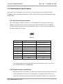
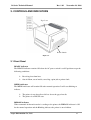
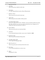
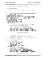
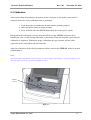
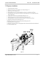
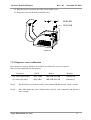
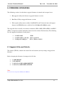
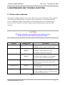
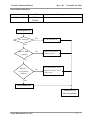
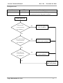
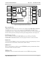
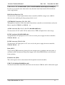
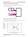
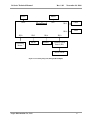
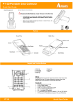
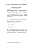
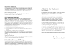
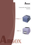
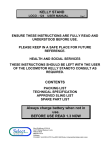
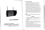
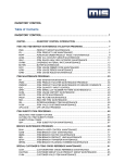
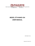
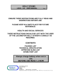
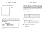
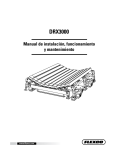
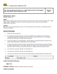
R-Series Technical Manual
Rev. 1.02
November 24, 2008
R-Series Technical Manual
Rev. 1.02
Argox Information Co., Ltd.
R-Series Technical Manual
Rev. 1.02
November 24, 2008
TABLE OF CONTENTS
R-Series Technical Manual ........................................................................................................... 1
1. GENERAL INTRODUCTION ................................................................................................ 4
1.1 Scope ................................................................................................................................. 4
1.2 Printer description ............................................................................................................. 4
1.3 Related manuals ................................................................................................................ 4
2. PRINTER SPECIFICATION .................................................................................................. 5
2.1 Printing .............................................................................................................................. 5
2.2 Fonts .................................................................................................................................. 5
2.3 Bar code............................................................................................................................. 6
2.4 Media ................................................................................................................................. 6
2.5 Electrical and operating environment ............................................................................... 7
2.6 Physical dimension ............................................................................................................ 7
2.7 Agency list ......................................................................................................................... 7
2.8 Communication interface .................................................................................................. 7
2.9 Communication specifications .......................................................................................... 8
2.10 The difference between R- Series and R-xxxK Series .................................................... 9
3. CONTROLS AND INDICATORS ......................................................................................... 10
3.1 Front Panel ...................................................................................................................... 10
3.2 Rear Panel ....................................................................................................................... 11
4. OPTIONS ................................................................................................................................. 13
4.1 Cutter mechanism ............................................................................................................ 13
4.2 FONT module.................................................................................................................. 14
4.3 Dispenser ......................................................................................................................... 14
4.4 RTC module .................................................................................................................... 14
5. SETUP AND DIAGNOSTIC .................................................................................................. 15
5.1 Inlet power voltage and grounding.................................................................................. 15
5.2 Performing the self test ................................................................................................... 15
5.3 Calibration ....................................................................................................................... 18
5.4 Printer reset ..................................................................................................................... 19
6. ADJUSTMENTS ..................................................................................................................... 20
6.1 Media sensor position adjustment ................................................................................... 20
7. OPTIONAL PARTS INSTALLATIONS ............................................................................... 21
7.1 Cutter Installation ............................................................................................................ 21
7.2 Dispenser Installation ...................................................................................................... 24
8. FIRMWARE UPGRADING................................................................................................... 26
8.1 Upgrade Utility and Diskette........................................................................................... 26
8.2 Upgrade through Printer Utility ...................................................................................... 29
Argox Information Co., Ltd.
2
R-Series Technical Manual
Rev. 1.02
November 24, 2008
8.3 ROM files (R-200/R-200K, R-400/R-400K, and R-600) ............................................... 31
8.4 Upgrade Firmware by Add-On Card (R-400plus/R-400Kplus Only) ............................. 32
8.5 Verification ...................................................................................................................... 32
9. MAINTENANCE AND TROUBLE SHOOTING ............................................................... 33
9.1 Printer status indication ................................................................................................... 33
9.2 Trouble Shooting ............................................................................................................. 34
9.3 Clearance ......................................................................................................................... 38
9.4 Replacement .................................................................................................................... 39
10. OPERATIONAL THEROREM ........................................................................................... 41
10.1 System block diagram ................................................................................................... 41
10.2 Panel board block diagram and description .................................................................. 47
10.3 Sensor board diagram and description .......................................................................... 47
10.4 Wiring diagram .............................................................................................................. 48
11. RECOMMENDED SPARE PARTS..................................................................................... 50
12. ASSEMBLY DRAWING ....................................................................................................... 51
Argox Information Co., Ltd.
3
R-Series Technical Manual
Rev. 1.02
November 24, 2008
1. GENERAL INTRODUCTION
1.1 Scope
This manual contains the information necessary for the proper maintenance Refine series label
printers of ARGOX. Most of the information included relates to hardware and mechanical parts.
1.2 Printer description
The ARGOX R-Series printer is a high-performance low-cost direct thermal and thermal transfer
label printer. Its user-friendly design and affordable price set new standard for the heavy-duty
label printer in retail, office and industrial applications.
The printer is designed with the most efficient memory management technology- True Speed,
prints up to 4 inches/second for R-200/R-200Kand R-600; 6 inches/second for R-400/R-400K
and R-400plus/R-400Kplus. When bundled with its smart printer driver, the user can easily print
a label by using any Windows applications, e.g. Microsoft Word, ArgoBar, Codesoft, Bar Tender,
Nicelabel under Windows XP/2000/98/95, Me, and NT. All popular bar codes and fonts are
resident in the printer memory to handle versatile application.
The solidly designed mechanism allows quick and easy media and ribbon loading. The optional
dispenser and cutter provide the alternatives of fan-fold label and continuous media handling.
1.3 Related manuals
User’s manual (Part No. 49-R4002-003).
Programmer’s manual.
Argox Information Co., Ltd.
4
R-Series Technical Manual
Rev. 1.02
November 24, 2008
2. PRINTER SPECIFICATION
2.1 Printing
R-200
R-200K
Type
R-400
R-400K
Thermal transfer and direct thermal
Resolution
203 dots/inch (8 dots/mm)
Max print width
4.25” (108mm)
4.25”(108mm)
Max print length
8” (203mm)
43” (1066mm)
Max print speed
4”(102mm) per second
6” (152mm) per second
512K bytes DRAM
2M bytes DRAM
Memory
Ribbon
Inside coating ribbon Outside coating ribbon Inside coating ribbon Outside coating ribbon
Emulation
PPLB
R-400plus
Type
PPLA and PPLB
R-400Kplus
R-600
Thermal transfer and direct thermal
Resolution
203 dots/inch (8 dots/mm)
300 dots (12 dots/mm)
Max print width
4.25” (108mm)
4.16”(104mm)
Max print length
43” (1066mm)
30” (762mm)
Max print speed
6”(152mm) per second
4” (102mm) per second
Memory
Ribbon
Emulation
2M bytes DRAM
Inside coating ribbon Outside coating ribbon
Inside coating ribbon
PPLA, PPLB and PPLZ
PPLA and PPLB
2.2 Fonts
Text fonts:
Printer Programming Language A (R-400/R-400K, R-400plus/R-400Kplus, and
R-600):
Courier (including PC set, Legal, ECMA94 and Roman-8), 7 alphanumeric fonts,
OCR-A/B, ASD smooth font. All fonts sizes are expandable by 24x24 (Refer to
the programmer’s manual).
Printer Programming Language B (R-200/R-200K, R-400/R-400K,
R-400plus/R-400Kplus, and R-600):
5 alphanumeric fonts. All fonts sizes are expandable by 24x24. (Refer to the
programmer’s manual).
Argox Information Co., Ltd.
5
R-Series Technical Manual
Rev. 1.02
November 24, 2008
Printer Programming Language Z (R-400plus/R-400Kplus):
15 internal bitmap fonts (including OCR A/B and SYMBOL) and one scalable
font (CG Triumvirate Bold Condensed). (Refer to the programmer’s manual).
Character rotation:
0, 90, 180 and 270 degree, 4-direction rotation.
2.3 Bar code
Bar code type:
Printer Programming Language A:
Code39, Code93, Code128/subset A, B and C, Codabar, Interleave 2 of 5, UPC
A/E/2 and 5 add-on, EAN 13/8, UCC/EAN-128, UCC/EAN-128 Random Weight,
Postnet, Plessey, HIBC, Telepen, FIM. MaxiCode, PDF-417, Data matrix.
Printer Programming Language B:
Code39, Code93, Code128/subset A, B and C, Codabar, Interleave 2 of 5, UPC
A/E/2 and 5 add-on, EAN 13/8, UCC/EAN-128, Postnet, Matrix 2 of 5,
Code-128UCC, PDF-417 and MaxiCode.
Printer Programming Language Z:
Code11, Interleave 2 of 5, Code39, Code93, EAN 13/8, UPCA/E, Code128/subset
A, B and C, Industrial 2 of 5, Standard 2 of 5, Codabar, UPC/EAN Extensions,
MSI, Plessey, PostNet, PDF-417, MaxiCode, DataMatrix, and QR code.
2.4 Media
Media type:
Thermal direct:
Direct thermal paper or vinyl, visible light and infrared scannable label, tag stock,
butt cut or die cut, with various adhesives.
Thermal transfer:
All above media, plus thermal transfer paper and tags, butt cut or die cut with
various adhesives.
Argox Information Co., Ltd.
6
R-Series Technical Manual
Max label roll diameter:
Label indexing:
Rev. 1.02
November 24, 2008
6” (152mm) outside diameter.
Black stripe and gap.
2.5 Electrical and operating environment
Electrical (R-200/R-200K):
19V AC, 50~60Hz.
4 Amps
Electrical (R-400/R-400K, R-400plus/R-400Kplus and R-600):
90V AC to 250V AC, 50~60Hz.
2 Amps/110V AC, 1 Amps/220V AC.
Environment:
Operation 40°~140 (4°~38), 10~90% non condensing.
Storage -40~140(-4°~60)
2.6 Physical dimension
Weight:
8.41bs(3.85kg) ~ 9.31lbs(4.2kg).
Size:
W12.4” x D9.1” x H8.6” (W314 x H231 x L218mm).
2.7 Agency list
CE, FCC class A, CCC, UL and CUL.
2.8 Communication interface
Serial interface:
RS-232 serial (1200~38400BPS), 8 data bits, 1 stop bit, no parity.
Parallel interface: Centronics parallel port.
USB interface:
USB 2.0 Full Speed (R-400plus/R-400Kplus only).
Argox Information Co., Ltd.
7
R-Series Technical Manual
Rev. 1.02
November 24, 2008
2.9 Communication specifications
Argox R-Series Label printers send and receive messages through serial, parallel or USB
(R-400plus only) communication interface. Printer checks each interface for incoming message
automatically.
2.9.1 Serial interface specification
The serial interface of R-Series printer is a standard RS-232C port with standard 9-pin
(DB9-S) connector located at the rear of the printer. The baud rate is user selectable by
sending command to the printer. Data bit number can be set as 7/8 data bits one/no parity
for both sending and receiving.
Figure 2-1
Pin No.
Direction
1
Description
Shorted to Pin – 6
2
IN
RxD
3
OUT
TxD
4
N.C.
5
GROUND
6
Shorted to Pin – 1
7
OUT
RTS
8
IN
CTS
9
OUT
+5V
Table 2-1
Pin assignment and description of serial port
For recommended connection details between host and printer, please refer to the
user’s manual (Part No. 49-R4002-003).
2.9.2 Parallel interface specification
The parallel interface of the R-Series printer is standard Centronics port with standard
36-pin connector located at the rear of the printer. A standard parallel cable can be
used for the interconnection between the host controller and the R series label printer.
Argox Information Co., Ltd.
8
R-Series Technical Manual
Rev. 1.02
November 24, 2008
Pin No.
Direction
Description
Pin No.
Direction
Description
1
IN
/STROBE
13
OUT
SELECT
2
IN
DATA1
14, 15
----
N.C.
3
IN
DATA2
16
OUT
CROUND
4
IN
DATA3
17
OUT
CROUND
5
IN
DATA4
18
----
N.C.
6
IN
DATA5
19~30
OUT
GROUND
7
IN
DATA6
31
----
N.C.
8
IN
DATA7
32
OUT
/FAULT
9
IN
DATA8
33~36
----
N.C.
10
OUT
/ACK
11
OUT
BUSY
12
OUT
PE
Table 2-2
Pin assignment and description of parallel port
2.9.3 USB Interface specification
This port complies with USB 2.0 Full Speed (R-400plus/R-400Kplus only).
Pin
Signal
Description
1
VBUS
2
D-
Differential data signaling pair-
3
D+
Differential data signaling pair+
4
GND
+3.3V
Table 2-3 Pin assignment and description of USB port
2.10 The difference between R- Series and R-xxxK Series
R-200, R-400, and R-400plus use BUSH-RIBBON (Part No. 42-R4023-001) for inside coating
ribbon.
R-200K, R-400K, and R-400Kplus use BUSH-RIBBON WHITE (Part No. 42-R4023-011) for
outside coating ribbon.
Argox Information Co., Ltd.
9
R-Series Technical Manual
Rev. 1.02
November 24, 2008
3. CONTROLS AND INDICATORS
Top Cover
Power Switch
Figure 3-1
3.1 Front Panel
READY indicator
The READY indicator remains ON when the AC power switch is at ON position except the
following conditions:
Receiving data from host.
Out of ribbon, out of media, canceling a print job or printer fault.
MEDIA indicator
The MEDIA indicator will remain ON under normal operation. It will start blinking to
indicate:
The printer is out of media or fails to detect the gap of media.
The printer is at PAUSE state.
RIBBON indicator
When command of thermal transfer is sending to the printer, the RIBBON indicator is ON
for the normal operation and the Blinking indicates the printer is out of ribbon.
Argox Information Co., Ltd.
10
R-Series Technical Manual
Rev. 1.02
November 24, 2008
When direct thermal command is sent to the printer, the RIBBON indicator is OFF and the
printer will ignore ribbon detection during printing.
FEED Button
The FEED button forces the printer to feed one label when printer is in idle (not printing) or
in PAUSE state.
Holding down the FEED button then turning on the power switch, the printer will perform a
self-test and a configuration report will be printed.
PAUSE Button
The PAUSE button stops and restarts the printing process in normal operation. If the
PAUSE button is pressed while printing is in progress, the printing stops once current label
is completed. Press this button again to restart the printing.
Holding down the PAUSE button then turning ON the power switch, the printer will
perform the media sensor calibration.
CANCEL Button
The CANCEL button interrupts and deletes the current printing job. If an error occurs,
pressing this button to cancel the error indication.
Holding down the CANCEL button then turning on the power switch, the printer will
perform a system reset, all the parameters which are stored in EEPROM will be reset to
factory default settings.
3.2 Rear Panel
Centronics connector (parallel port)
For parallel port connection. Mostly it is connected to the printer port of a PC.
RS232 connector (serial port)
For serial port connection. Mostly it is connected to the COM port of a PC.
Power switch
Controls application of AC power to printer. Turning the printer ON while holding down
certain front panel button will cause the printer to perform the self test, calibration or
system reset. The power should be turned OFF to connect or disconnect any internal cable.
Argox Information Co., Ltd.
11
R-Series Technical Manual
Rev. 1.02
November 24, 2008
Power Jack (R-200/R-200K)
To connect the power plug from the power adaptor.
Warning:
To protect the power, prevent the power jack from touching the Centronic’s hooks.
AC power socket (R-400/R-400K, R-400plus/R-400Kplus, and R-600)
For AC power connection.
USB connector (USB port)
Connector for USB application. Usually, it is connected to the USB port of a PC (R-400
plus/R-400Kplus only).
AC Electrical Outlet
Power switch
Power socket
USB
Parallel Port
Figure 3-2
RS232 Serial Port
Rear panel of R-400plus/R-400Kplus
Power Jack
Power adaptor
Parallel Port
RS232 Serial Port
Figure 3-3 Rear panel of R-200/R-200K
Argox Information Co., Ltd.
12
R-Series Technical Manual
Rev. 1.02
November 24, 2008
4. OPTIONS
4.1 Cutter mechanism
Optional A2 cutter, which is available for cutting label, tags or tickets, was refined into the new
type, A2+ cutter. Firmwares of all A-series label printers have been phased in A2+ cutter as the
default type of cutter.
Default
Type
Printer
R-400 /
R-400K
…
R-400plus/
R-400kplus
—
R-600
…
A2 Cutter
A2+ Cutter
Firmware Version (PPLA)
Firmware Version (PPLA)
R2A0-4.01
R2A0-4.02
122204
051105
—
—
R3A0-3.02
R3A0-3.03
R3A0-3.04
041405
021606
060906
R2A0-5.00
051806
…
…
…
Table 4-1
Default
Type
Printer
R-200/
R-200K
—
R-400 /
R-400K
…
R-400plus/
R-400kplus
—
R-600
…
A2 Cutter
A2+ Cutter
Firmware Version (PPLB)
Firmware Version (PPLB)
R1B0-1.00
R1B0-1.01
R1B0-1.02
042005
110605
051506
R2B0-3.06
R2B0-3.07
062905
111505
—
—
R3B0-3.05
R3B0-3.06
R3B0-3.07
092005
022806
060806
R2B0-4.00
052606
…
…
…
…
Table 4-2
Default
Type
Printer
R-400plus/
R-400kplus
…
A2 Cutter
A2+ Cutter
Firmware Version (PPLZ)
Firmware Version (PPLZ)
R2Z0-1.01
R2Z0-1.02
R2Z0-2.00
051804
122605
052506
…
Table 4-3
Argox Information Co., Ltd.
13
R-Series Technical Manual
Rev. 1.02
November 24, 2008
To use A2 cutter with printer firmware of R-400/R-400K and R-400plus/R-400Kplus, which has
been phased in A2+ cutter, users can send the command <ESC>KIT to adjust the rotational angle
of A2 cutter to avoid frequently label stuck and cutter jammed, or downgrade the firmware to the
former version (ex. R2B0-3.07).
Syntax
<ESC>KITm
Parameter
m: cutter delay time, a binary byte.
m = 0x00 for A2+ cutter (default).
m = 0x01 ~ 0xFF for A2 cutter (0x1E is recommended).
4.2 FONT module
Font module is used to store special fonts such as Traditional Chinese, Simplified Chinese,
Korean and Japanese
4.3 Dispenser
Dispenser provides the automatic peel-off function.
4.4 RTC module
The RTC module consists of two major components. A Real Time Clock with battery back-up &
a on-board flash memory. The RTC module provides function to enable the user to print time &
date messages on the label. The on-board flash memory can be used as permanent data storage
such as downloaded forms, graphics and true type fonts.
Argox Information Co., Ltd.
14
R-Series Technical Manual
Rev. 1.02
November 24, 2008
5. SETUP AND DIAGNOSTIC
5.1 Inlet power voltage and grounding
The R-Series printer is designed for both 110V AC and 220V AC outlet. The line voltage should
not lower than 90V AC or higher than 250V AC and the printer should be connected to a
properly grounded receptacle.
5.2 Performing the self test
Once the printer is first installed, a self-test should be performed. To perform the self-test, please
follow the procedure:
1.
2.
Turn off the power.
Load the media and ribbon properly.
3.
4.
5.
Press and hold the FEED button then turn on the power.
Release the FEED button after printer starts to print.
The configuration report will be printed out as Figure 5-1 and Figure 5-2.
6.
To return the printer to normal operation, please turn the power OFF and ON again or
press the CANCEL button for one second, otherwise the printer will enter dump mode,
all input data will not be interpreted.
Contents and information of R-Series “Self Test Label” are as the following:
1.
Printer programming language and version information
The printer programming language, firmware version and date information are listed
on the first line of the report.
2.
RS-232 Protocols
It contains data frame of RS-232 interface: baud rate, parity, data bit number, and stop
bit number.
3.
Standard RAM size
This message shows standard RAM size in the printer.
4.
Available RAM size
This message shows available memory can be used to hold the downloadable graphics,
Argox Information Co., Ltd.
15
R-Series Technical Manual
5.
Rev. 1.02
November 24, 2008
forms and soft fonts.
Code Page
This message shows symbol set of the font.
6.
Print Mode
It is either Thermal Transfer mode or Direct Thermal mode.
7.
Reflective Sensor
This message shows the media sensor type.
8.
Label Count
This message shows the number of labels printed.
9.
Accumulated Print Length
It keeps the length printed in meters. With this, you may check the print head warranty.
The value will not be reset even you replace the print head or any components. It is
changed only when the main board is replaced.
10. Flash On Board
This message shows the size of on-board flash.
11. Checksum
Used to check the firmware flash is correct or not. It should be ‘0000’.
12. H. Position Adjust
This message shows horizontal shift position.
13. LAB LEN (TOP to TOP)
Label length (Including gap height).
14. Media Sensor Level
This message shows the sensitivity of the media sensor.
15. Font Image
Used to check internal fonts are correct or not.
16. Speed
Printing speed setting.
Argox Information Co., Ltd.
16
R-Series Technical Manual
Rev. 1.02
November 24, 2008
17. Expansion RAM
This message shows expansion RAM size in the printer.
18. No. Of DL Soft Fonts
This message shows the number of soft fonts downloaded in the printer.
1
2
3
4
6
8
10
11
12
13
14
5
7
9
15
Figure 5-1 R-400 Self-test pattern
17
18
16
Figure 5-2 R-200 Self-test pattern
Argox Information Co., Ltd.
17
R-Series Technical Manual
Rev. 1.02
November 24, 2008
5.3 Calibration
After the first time of installation, the printer media is changed, or the media sensor board is
replaced, the media sensor calibration must be performed.
1. Load the media (and ribbon for thermal transfer printing) properly.
2. Move the media sensor to proper position.
3. Press and hold down the PAUSE button then turn on the power switch.
During the media calibration, 6 inches of media will be fed out. MEDIA indicator will be
blinking for a few seconds during calibration is proceeding. Then turn on printer again after the
calibration is completed. Without the proper calibration, the gap detection will not stable
especially for the small labels and special media.
After the calibration, all the related parameters will be stored in the EEPROM, which is located
on Main Board.
Note:
After the first time of installation or the media type is changed, this procedure must be carried out. Failing to do it,
the media-empty and media-gap detection might be incorrect.
Media
Sensor
Figure 5-3
Argox Information Co., Ltd.
18
R-Series Technical Manual
Rev. 1.02
November 24, 2008
5.4 Printer reset
The procedure of resetting the printer:
1.
Turn off the printer.
2.
3.
Press and hold the CANCEL button then turn on the printer.
Release the CANCEL button when RIBBON indicator blinks for three times and
READY indicator blinks for on time.
The following parameters will be reset to the default value:
Label parameters.
Printing darkness.
Printing speed.
Symbol set.
Others for specific emulation.
Argox Information Co., Ltd.
19
R-Series Technical Manual
Rev. 1.02
November 24, 2008
6. ADJUSTMENTS
6.1 Media sensor position adjustment
The media sensor senses either the gap between labels or a hole or notch in the media to
determine the position and length of the label or ticked stock.
When using label with gap, user can position the sensor anywhere in side the gap. But when
using media with notch or hole, it may be necessary to reposition the media sensor.
1.
2.
Open the print head module.
Load the media properly.
3.
4.
Adjust the sensor by moving the media sensor adjustment lever left or right.
Close the print head module and top cover.
Figure 6-1
Argox Information Co., Ltd.
20
R-Series Technical Manual
Rev. 1.02
November 24, 2008
7. OPTIONAL PARTS INSTALLATIONS
CAUTION
The printer electronics are susceptible to static discharge. Wear
an anti-static wrist and attach it to the printer chassis.
7.1 Cutter Installation
1. Turn off the power switch.
2. Remove the top cover and middle cover shown in Figure 7-1.
Figure 7-1
Argox Information Co., Ltd.
21
R-Series Technical Manual
Rev. 1.02
November 24, 2008
3. Remove the E-ring (I), gear (27) and release the screw (F).
4. Remove the bracket-peeler (71) from the module.
Figure 7-2
5. Secure two attached screws (B) for the cable connector as Figure 7-3.
6. Add a cutter baby board to JP29 on the main board (R-400/R-400K and R-600).
Add a motor driver IC 3717 to U19 on the main board (R-200/R-200K).
7. Plug the cable connector into JP13.
Figure 7-3
Argox Information Co., Ltd.
22
R-Series Technical Manual
Rev. 1.02
November 24, 2008
8. Click back the middle cover.
9. Click back the top cover.
10. Secure two attached screws (M) for the cutter.
11. Plug the cutter cable into external connector shown in Figure 7-4.
External Connector
Cutter Cable
Figure 7-4
Install the media and the ribbon after the cutter is properly installed.
1. Put the media end on the roller.
2. Close the printer module.
3. Turn on the printer.
4. Press the FEED button to let the media end to go through the cutter.
Argox Information Co., Ltd.
23
R-Series Technical Manual
Rev. 1.02
November 24, 2008
7.2 Dispenser Installation
1. Turn off the power switch.
2. Remove the top cover and middle cover shown in Figure 7-1.
3. Remove gear (27) and gear (31).
4. Plug spring-peeler (83) into the right hole on chassis 2 and lock screw (F) up.
5. Put shaft-peeler (86) and peeler-switch (88) into shaft-peeler (87) and then insert it in
hole on right side.
6. Guide peeler-switch (85) going through shaft-peeler (87).
7. Hook spring-peeler (83) on the circle notch of shaft-peeler (87).
8. Put spring-peeler (84) into the left hole of chassis 2 and lock screw (F) up.
9. Put peeler-switch (89) into shaft-peeler (87).
10. Hook spring-peeler (84) on the circle notch of shaft-peeler (87).
11. Put back gear (27) and gear (31).
12. Mount the cable into chassis 2 and plug the other side into the label on the main board.
13. Close the middle cover.
Figure 7-5
Argox Information Co., Ltd.
24
R-Series Technical Manual
Rev. 1.02
November 24, 2008
14. Plug the peeler sensor into the cable on the middle cover.
15. Put peeler cover on the front of middle cover.
P E E LE R
SE N SO R
Figure 7-6
7.2.1 Dispenser sensor calibration
If the dispenser sensor is failed to detect label, to calibrate the sensor is required.
There are two commands for this purpose:
Command
Set sensor without label
Set sensor with label
ASCII
<ESC>$R0
<ESC>$R1
Binary
1BH 24H 52H 30H
1BH 24H 52H 31H
Remark
Command 0
Command 1
Step 1:
Put the label away from the sensor, send command 0 and wait for 2 more seconds.
Step 2:
Put a label under the sensor (10 mm below), hold it, send command 1 and wait for 2
more seconds.
Argox Information Co., Ltd.
25
R-Series Technical Manual
Rev. 1.02
November 24, 2008
8. FIRMWARE UPGRADING
The following sections describe how to upgrade firmware in normal and corrupted cases.
1. Run upgrade utility and diskette to upgrade firmware version.
2. Run Pinter Utility to upgrade firmware version.
3. When update utility unsuccessfully, flash ROM U8 and U9 must be burn with proper
firmware by EPROM writer or Add-On Card (R-400plus/R-400Kplus only).
The Argox R-Series basically can run three emulations, PPLA (DPL), PPLB (EPL2) and PPLZ
(ZPL2). It depends on which emulation is burned on the on-board flash memory. The following
lists the supported emulation of each printer.
R-200/R-200K:
R-400/R-400K and R-600:
PPLB.
PPLA and PPLB.
R-400plus/R-400Kplus:
PPLA, PPLB and PPLZ.
8.1 Upgrade Utility and Diskette
The diskette (ZIP file) contains the related files and data that you may change or upgrade the
firmware.
Before changing the firmware, decompress the file first.
1.
2.
3.
4.
C:\>MD ARGOX
C:\CD ARGOX
C:\ARGOX\>COPY A:README.TXT
C:\ARGOX\>A:PKUNZIP A:FW.ZIP
Note:
You may also decompress the ZIP file from Windows.
Argox Information Co., Ltd.
26
R-Series Technical Manual
Rev. 1.02
November 24, 2008
8.1.1 Procedure to update firmware (PPLA emulation)
1. Turn on the printer and wait for three seconds.
2. Set PC to MS-DOS (exit from Windows).
3. C:\ARGOX\>PPLA
………
4. When “Upgrade Complete!” message is displayed on the screen, turn off the power until
all LEDs go OFF then turn on the printer again.
5. When update successfully, please reset the printer (press CANCEL button then turn on
the power).
8.1.2 Procedure to update firmware (PPLB emulation)
1. Turn on the printer and wait for three seconds.
2. Set PC to MS-DOS (exit from Windows).
3. C:\ARGOX\>PPLB
… … …
4. When “Upgrade Complete!” message is displayed on the screen, turn off the power until
all LEDs go OFF then turn on the printer again.
5. When update successfully, please reset the printer (press CANCEL button then turn on
the power).
8.1.3 Procedure to update firmware (PPLZ emulation)
1. Turn on the printer and wait for three seconds.
2. Set PC to MS-DOS (exit from Windows).
3. C:\ARGOX\>PPLZ
… … …
4. When “Upgrade Complete!” message is displayed on the screen, turn off the power until
all LEDs go OFF then turn on the printer again.
5. When update successfully, please reset the printer (press CANCEL button then turn on
the power).
Note:
It is very important that DO NOT TURN OFF the printer during changing the firmware till “Upgrade Complete!” is
present. Otherwise unpredictable results may occur.
Argox Information Co., Ltd.
27
R-Series Technical Manual
Rev. 1.02
November 24, 2008
8.1.4 Failing to upgrade firmware
If the whole procedure cannot be completed within three minutes or “Printer Time Out” happens,
please check the communication cable that is securely connected to the printer and PC. Then
restart the printer and rerun all updating procedure.
For example:
Write fault error writing device LPT1
Abort, Retry, Ignore, Fail?
You just type <ctrl-C> and then Y to terminate the procedure.
- Printer: turn off and turn on the printer.
- PC: Abort the transmission and type
>PPLA or
PPLB
Argox Information Co., Ltd.
or PPLZ
28
R-Series Technical Manual
Rev. 1.02
November 24, 2008
8.2 Upgrade through Printer Utility
1. Start Argox application software, Printer Utility.
2. Select “Download”.
3. Select printer model, printer language and interface.
4. Click on “Browse” button to choose the firmware.
Argox Information Co., Ltd.
29
R-Series Technical Manual
Rev. 1.02
November 24, 2008
5. Select “Local Disk C ” “ARGOX” “400-b.bin”, then click “Open”.
Argox Information Co., Ltd.
30
R-Series Technical Manual
Rev. 1.02
November 24, 2008
6. Click “Download” to upgrade the firmware.
8.3 ROM files (R-200/R-200K, R-400/R-400K, and R-600)
Following procedures can generate the binary files for U8 and U9:
1. >EPROMA.BAT
This command will generate AU8.BIN and AU9.BIN
2. >EPROMB.BAT
This command will generate BU8.BIN and BU9.BIN
These binary files are used for burning the flash ROMs on the EPROM writer.
Argox Information Co., Ltd.
31
R-Series Technical Manual
Rev. 1.02
November 24, 2008
8.4 Upgrade Firmware by Add-On Card (R-400plus/R-400Kplus Only)
In very abnormal case, the Boot-Up program located at BOOT sector of flash ROM in
R-400plus/R-400Kplus might be corrupted (supposedly it is impossible to happen). This will
cause the printer fail to perform firmware upgrade with the above normal procedures. In this case,
you might refer to the following to upgrade the firmware.
1. Refer to step 1~2 in section 7.1 and Figure 7-1 to disassemble the printer till expansion
slot (JP11) and JP5 are accessible.
2.
3.
4.
5.
All the jumpers on JP5 (1,2 position) should be put on 2,3 position.
Put “Add-On Card” (it is a 2MB Flash Memory Card with “Booter firmware”) on JP11.
Turn on the printer and wait until “MEDIA” and “RIBBON” LEDs blinking alternately.
Turn off the printer.
6. Remove “Add-On Card” from JP11.
7. Put all the jumpers on JP5 to the NORMAL (1, 2 position) position again.
8. Put top and middle covers back to reassemble the printer.
9. Turn on the printer, if “READY” LED blinks four times that means the corrupt case is
solved.
10. Then refer to steps in section 8.1 or 8.2 to upgrade firmware.
8.5 Verification
To confirm that you had successfully changed the firmware you just check the self-configuration
printout.
1. Turn off the printer until all the LEDs are OFF.
2. Press FEED button and turn on the printer.
3. When the motor starts rotation, release the button.
Check the version code and date code, also the checksum code (must be ‘0000’).
Argox Information Co., Ltd.
32
R-Series Technical Manual
Rev. 1.02
November 24, 2008
9. MAINTENANCE AND TROUBLE SHOOTING
9.1 Printer status indication
The printer has built-in monitors for the status. The status and error indications will be displayed
on the front panel LED indicators. Generally, when a malfunction or an abnormal condition
occurs, the READY LED will keep blinking, in the meantime printing and communication
between the host and printer will stop. To understand the problem, please check the LED
indicators.
CAUTION
The printer electronics are susceptible to static discharge. Wear
an anti-static wrist and attach it to the printer chassis.
Situation
Blinking LED
Description
PAUSE
MEDIA
The printer is at pause status. Press PAUSE or
CANCEL button to return to normal status.
MEDIA OUT
MEDIA
READY
Both LEDs blink synchronously.
The media is not installed or used up.
Printer fails to detect the media gap.
RIBBON OUT
RIBBON
READY
Both LEDs blink asynchronously.
The ribbon is not installed or end-of-ribbon
occurred. Load new ribbon to the printer.
SERIAL IO ERROR
READY
The format or baud rate of the RS232
communication is inconsistent between the
printer and host.
CUTTER FAILED
READY
The cutter can not cut off the media, check the
media and cutter.
MEMORY FULL
READY
The printer buffer is full caused by the loaded
soft fonts, graphics or forms. Check the format
of these data. Call for service.
Table 9-1
Argox Information Co., Ltd.
33
R-Series Technical Manual
Rev. 1.02
November 24, 2008
9.2 Trouble Shooting
No indication:
Status
LED
Description
All LEDs are OFF
All LEDs are OFF
Out of power or printer out of work
Power
No
connected?
Connect power
Yes
Power switch
No
is “ON” ?
Switch ON
Yes
Power supply
Yes
Replace the fuse
fuse broken?
No
Internal cable
connected
No
Connect the cable
properly
Yes
Power supply, main
board or panel board
is out of work
Argox Information Co., Ltd.
Switch power on
then start printing
34
R-Series Technical Manual
Rev. 1.02
November 24, 2008
Out of media indication:
Status
LED
Description
MEDIA OUT
MEDIA
READY
The media is not installed or used up.
Printer is failing to detect the media gap.
Switch power off
Out of media?
Yes
Load a new media roll
No
Media stuck
Yes
or jammed
Remove the stuck or
jammed media
No
Fail to detect
Yes
media gap?
No
Media loaded
No
Reload media
correctly?
Yes
Media sensor is at
No
proper position?
Move the sensor to
proper position
Yes
Continuous type
of media is used?
No
Disable gap
detection
Switch power on
Perform the media sensor
then start printing
calibration or the media
sensor is out of work.
Argox Information Co., Ltd.
35
R-Series Technical Manual
Rev. 1.02
November 24, 2008
Out of ribbon indication:
Status
LED
RIBBON OUT
RIBBON
READY
Description
The ribbon is not installed or out of ribbon.
Switch power off
Out of ribbon?
Yes
Load a new ribbon
No
Ribbon stuck
Yes
or jammed
Remove the stuck or
jammed ribbon
No
Ribbon is
moving during
printing?
Check the ribbon sensor.
Yes
Replace with new sensor
if necessary.
No
Check mechanism
Switch power on
then start printing
Argox Information Co., Ltd.
36
R-Series Technical Manual
Rev. 1.02
November 24, 2008
Serial port error:
Status
LED
Description
SERIAL IO ERROR
READY
The format or baud rate of the RS232 communication
is inconsistent between the printer and host.
Switch power on
Is the baud rate
No
consistent between
Set the same baud rate
in PC and Printer
PC and Printer?
Yes
Is the data bit number
No
consistent between
Set the same data bit
number in PC and Printer
PC and Printer?
Yes
Is the parity type
consistent between
No
Set the same parity type
in PC and Printer
PC and Printer?
Yes
Switch power on
then start printing
Argox Information Co., Ltd.
37
R-Series Technical Manual
Rev. 1.02
November 24, 2008
9.3 Clearance
CAUTION
The printer electronics are susceptible to static discharge. Wear
an anti-static wrist and attach it to the printer chassis.
There are some components need to be clean-up occasionally:
Thermal print head
The debris of thermal paper or riboon may collect on the print head causing characters or bar
codes to appear light or faded. To clean the print head, wet a soft paper towel with isopropyl
rubbing alcohol and use the damp towel to rub the dirt from the print head surface.
It is recommended to clean the print head after every roll of ribbon.
Platen roller
If the roller becoms contaminated with grit, label adhesive, or ink, printing quality may be
adversely affected. To clean the roller, using a clean cloth and alcohol, wipe off any accumulated
debris.
Media sensor
The dirt on the paper sensor will cause the miss or unstable detection of label gap. Clean it with
bristle brush or air blow once in a while.
Note:
Switch off the power before cleaning!
Argox Information Co., Ltd.
38
R-Series Technical Manual
Rev. 1.02
November 24, 2008
9.4 Replacement
CAUTION
The printer electronics are susceptible to static discharge. Wear
an anti-static wrist and attach it to the printer chassis.
TPH (thermal print head) replacement
To replace the print head, please follow the procedure as shown on Figure 9-1, 9-2. It is also
possible to replace the TPH without remove the print head module.
1. Remove the shaft-tph (65) from the module.
Figure 9-1
Argox Information Co., Ltd.
39
R-Series Technical Manual
Rev. 1.02
November 24, 2008
2. Release the screw (E) and (A).
3. Remove the print head cable from the print head.
4. Remove the print head (56) from the bracket-tph(55).
Figure 9-2
Argox Information Co., Ltd.
40
R-Series Technical Manual
Rev. 1.02
November 24, 2008
10. OPERATIONAL THEROREM
10.1 System block diagram
10.1.1 System block diagram of R-400/R-400K and R-600
Panel Board
Ribbon Sensor
Main Board
Parallel
Cutter Peeler sensor
Port
TPH
Serial
Paper sensor
Port
Roller
Motor
Switching Power
90~250 V AC
Figure 10-1 R-400/R-400K and R-600 System Block Diagram
Argox Information Co., Ltd.
41
R-Series Technical Manual
Rev. 1.02
November 24, 2008
10.1.2 System block diagram of R-400plus/R-400Kplus
Panel Board
Parallel
Port
Ribbon sensor
Main Board
Cutter Peeler sensor
Serial
TPH
Port
Paper sensor
USB
Roller
2.0 Full
Speed
Motor
Switching Power
90~250 V AC
Figure 10-2 R-400plus System Block Diagram
10.1.3 System block diagram of R-200/R-200K
Panel Board
Parallel
Port
Ribbon sensor
Main Board
Cutter Peeler sensor
Serial
TPH
Port
Paper sensor
Roller
Motor
External AC Adaptor
Figure 10-3 R-200/R-200K System Block Diagram
Argox Information Co., Ltd.
42
R-Series Technical Manual
Rev. 1.02
November 24, 2008
R-Series printer consists of:
Main board
A four layers PCBA, consists of a micro-controller, EPROMs, EEPROM, DRAM, etc.
components requried for the printing functions.
Panel board
A one layers PCBA, consists of a three push button switches, three LED indicators for user’s
access, status and error indication.
Ribbon sensor
A two layer PCBA, consist of a reflective type object sensor designate for ribbon detection.
Media sensor
A two layer PCBA, consist of a reflective type object sensor designate for meida detection.
Thermal print head (TPH)
There are 832 heat elements consist in theR-200/R-200K TPH (864 heat elements for
R-400/R-400K/R-400plus and 1248 heat elements for R-600). Each heat element can be turn
on/off individually.
Motor
A bipolar hybrid stepping motor is used for carrying label and ribbon during printing.
Peeler sensor (option)
An two layer PCBA, consist of a reflective type object senosr designate to detect the printed
label is removed or still exit.
Cutter assembly (option)
Consisting of a DC motor, a switch , gears and a rotary cutter. It is used for cutting the printed
label automatically.
SPS (Switching Power supply)
The switching power supply converts the power (90V AC to 250V AC) to 24V DC. A 5 Amps
fuse is also included in the power supply for over current protection.
Power adapter (R-200/R-200K only)
Power adapter converts the input voltage (120V AC or 230V AC) to 19V AC. A 4Amps fuse is
also included in the adapter for over current protection.
Argox Information Co., Ltd.
43
R-Series Technical Manual
Rev. 1.02
November 24, 2008
Host controller
An equipment which can send the printing command to printer through RS232 serial port ,
Centronics parallel port or USB2.0 Full Speed (R-400plus only). Usually a PC is connected.
Panel
Board
TPH
Cutter
Extension
TPH
12Mhz
Cutter
Motor
Motor
Driver
MCU
Parallel
Driver
RS232
Driver
Paper/Media/Peeler
Sensor
Linear
Adaptor
PC
Bipolar
DRAM
Signals
Flash ROM
AC/DC
DC/DC
A1~A20
Converter
Regulator
D0~D15
256KX16
Figure 10-4 R-200 Main Board Block Diagram
Panel
Board
TPH
Cutter
Extension
TPH
Cutter
Motor
Motor
Driver
DRAM
MCU
Parallel
Driver
RS232
Driver
Paper/Media/Peeler
Sensor
Switching
Power
PC
Bipolar
20Mhz
Signals
Flash ROM
DC/DC
A1~A20
Converter
D0~D15
512KX16
Figure 10-5 R-400/R-600 Main Board Block Diagram
Argox Information Co., Ltd.
44
R-Series Technical Manual
Rev. 1.02
Panel
Board
TPH
Cutter
TPH
Cutter
Motor
Motor
Driver
Extension
20Mhz
DRAM
Parallel
MCU
Driver
USB Chip
Net 2890
Paper/Media/Peeler
Sensor
Switching
Power
PC
Bipolar
November 24, 2008
RS232
Signals
Driver
DC/DC
Converter
Flash ROM
A1~A20
512X16
D0~D15
Figure 10-6 R-400plus Main Board Block Diagram
Micro-controller (U6)
A HITACHI 16 bit RISC processor is selected as the controller for R-200/R-200K. A HITACHI
32 bit RISC processor is selected as the controller for R-400/R-400K and R-600. The rich
on-chip functions such as: Integrated timer, DMA controller, A/D convert, Serial communication
interface, Pattern generator and I/O ports make the printer high performance and compact size.
FLASH memory (U8, U9)
There are 256K bytes FLASH on R-200/R-200K main board (512K bytes FLASH on
R-400/R-400K and R-600 main board) to store the program, characters, and bar code fonts.
DRAM (U10)
A sixteen mega bits DRAM is selected as the medium of storage for the printing image. In order
to have fast access to the memory, 16 bits data bus width is selected.
EEPROM (U7)
There are some parameters, which are stored in EEPROM for printing, communication, ribbon
and media detection, and special controls.
TPH driver (U1)
Through these drivers, the control and data signals are feed to TPH for image printing.
Argox Information Co., Ltd.
45
R-Series Technical Manual
Rev. 1.02
November 24, 2008
Cutter driver (U2: R-200/R-200K) (JP29: R-400/R-400K/R-600/R-400plus/R-400Kplus)
In order to prevent the cutter from stuck, relay function cutter baby board will be handle the
cutter stop position.
RS232 driver/Receiver (U4)
To convert the serial port signal to/from micro-controller to RS232 voltage level, a RS232
driver/receiver with integral charge pump circuit is used.
CENTRONICS interface (U11, U13, U15)
Through these interface, all the data come from the host controller are latched them read by the
Micro-controller, EPROM, and DRAM…etc.
AC/DC converter (D1, C2, C3, C4, C5) (R-200/R-200K only)
To convert the AC 19V to DC 24V for motor drivers, TPH, and option deice cutter usage.
DC/DC regulator (R-200/R-200K only)
To regulator the 24V input power to 5V, to be used as the power supply for micro-controller,
EPROM, DRAM…etc.
DC/DC converter (U20, L1, D2)
To convert the 24V input power to 5V, to be used as the power supply for micro-controller,
EPROM, DRAM…etc.
Relay (RY2)
To prevent the TPH from being damaged by the unstable power condition when the printer is
switched on, RY2 disconnected the power supply (24V) to the TPH. RY2 has to be activated
before printing.
Extension slot (JP11)
This slot designate for the connection of all the optional extension modules.
USB (U2) (R-400plus/R-400Kplus only)
To convert between the data form address bus and data bus to USB D+ and D- differential signal.
Argox Information Co., Ltd.
46
R-Series Technical Manual
Rev. 1.02
November 24, 2008
10.2 Panel board block diagram and description
The Panel board consists of three push bottom switches and three LED indicators for user’s
access, status ,and error indication.
+5V
READY
MEDIA
RIBBON
Main Board
JP10
FEED
PAUSE
CANCEL
Figure 10-7 Panel Board Diagram
10.3 Sensor board diagram and description
The circuit of all the sensor board (Media sensor board, Ribbon sensor board and Peeler board) is
identical. A reflective sensor is used for these purposes.
Figure 10-8 Sensor Board Diagram
Argox Information Co., Ltd.
47
R-Series Technical Manual
Rev. 1.02
November 24, 2008
10.4 Wiring diagram
Panel
Motor
JP10
JP3
Linear
Main Board
JP21
JP13
Cutter
JP18
TPH
JP15
JP14
JP12
Media
Ribbon
Connect sensor
Board (JP1)
Adaptor
Peeler sensor
Figure 10-9 Wiring Diagram (R-200/R-200K)
Panel
Motor
JP10
JP22
Switching
Power
Main Board
JP17
JP13
Cutter
JP18
TPH
JP15
JP14
JP12
Media
Ribbon
Connect sensor
Board (JP1)
Peeler sensor
Figure 10-10 Wiring Diagram (R-400/R-400K, and R-600)
Argox Information Co., Ltd.
48
R-Series Technical Manual
Rev. 1.02
Panel
Motor
JP19
JP22
Switching
Power
November 24, 2008
Main Board
JP17
JP13
Cutter
JP18
TPH
JP15
JP14
JP12
Media
Ribbon
Connect sensor
Board (JP1)
Peeler sensor
Figure 10-11 Wiring Diagram (R400plus/R400Kplus)
Argox Information Co., Ltd.
49
R-Series Technical Manual
Rev. 1.02
November 24, 2008
11. RECOMMENDED SPARE PARTS
R-200/R-200K spare parts
Part Number
Description
55-R2000-001
R-200 Main Board
55-R4005-002
R-series Connect Sensor Board
55-R4001-011
R-series Panel Board
55-R4002-011
R-series Paper Sensor Board
55-R4003-012
R-series Ribbon Sensor Board
23-80004-002
R-200 Thermal Print Head
22-80024-006
Stepping Motor
50-20401-001
RS232 Cable
59-R2001-001
Linear Adaptor
59-R4003-001
Core Adapter (Ribbon)
59-R4002-001
Cutter (Option)
59-R4001-003
Dispenser Kit (Option)
42-R4020-011
Holder-Paper
R-400/R-400K spare parts
Part Number
Description
55-R4000-005
R-series Main Board
55-R4005-002
R-series Connect Sensor Board
55-R4001-001
R-series Panel Board
55-R4002-001
R-series Paper Sensor Board
55-R4003-002
R-series Ribbon Sensor Board
23-80013-001
R-400 Thermal Print Head
22-80024-006
Stepping Motor
50-20401-001
RS232 Cable
98-R4003-002
Switching Power Supply
59-R4003-001
Core Adapter (Ribbon)
59-R4002-004
Cutter (Option)
59-R4001-003
Dispenser Kit (Option)
42-R4025-001
Holder-Paper
Argox Information Co., Ltd.
50
R-Series Technical Manual
Rev. 1.02
November 24, 2008
R-400plus/R-400Kplus spare parts
Part Number
Description
55-R4000-007
R-series Main Board
55-R4005-001
R-series Connect Sensor Board
55-R4001-011
R-series Panel Board
55-R4002-001
R-series Paper Sensor Board
55-R4003-012
R-series Ribbon Sensor Board
23-80013-001
R-400plus Thermal Print Head
22-80024-006
Stepping Motor
50-20401-001
RS232 Cable
98-R4003-002
Switching Power Supply
59-R4003-001
Core Adapter (Ribbon)
59-R4002- 004
Cutter (Option)
59-R4001-003
Dispenser Kit (Option)
42-R4025-001
Holder-Paper
R-600 spare parts
Part Number
Description
55-R4000-005
R-series Main Board
55-R4005-002
R-series Connect Sensor Board
55-R4001-001
R-series Panel Board
55-R4002-001
R-series Paper Sensor Board
55-R4003-002
R-series Ribbon Sensor Board
23-83424-001
R-600 Thermal Print Head
22-80024-006
Stepping Motor
50-20401-001
RS232 Cable
98-R4003-002
Switching Power Supply
59-R4003-001
Core Adapter (Ribbon)
59-R6001-003
Cutter (Option)
59-R4001-002
Dispenser Kit (Option)
72-R4025-001
Holder-Paper
12. ASSEMBLY DRAWING
Argox Information Co., Ltd.
51
R-Series Technical Manual
Rev. 1.02
November 24, 2008
R-200
Argox Information Co., Ltd.
R-Series Technical Manual
Rev. 1.02
November 24, 2008
R-200K
Argox Information Co., Ltd.
53
R-Series Technical Manual
Rev. 1.02
November 24, 2008
R-400plus
Argox Information Co., Ltd.
54
R-Series Technical Manual
Rev. 1.02
November 24, 2008
R-400K plus
Argox Information Co., Ltd.
55
R-Series Technical Manual
Rev. 1.02
November 24, 2008
R-600
Argox Information Co., Ltd.
56