1
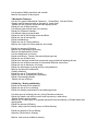
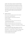
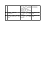
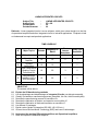
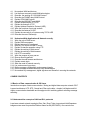
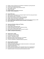
ELECTRONIC COMPONENTS AND DEVICES
Subject Title
:
Electronic Components and Devices
Subject Code
:
EC-105
Periods/Week
:
04
Periods/Year
:
120
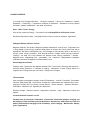
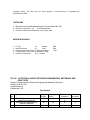
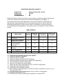
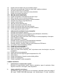
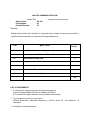
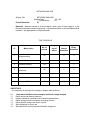
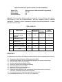
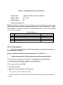
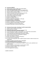
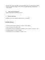
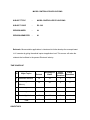
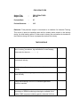
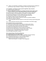
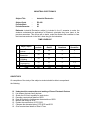
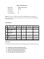
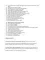
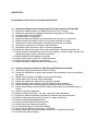
TIME SCHEDULE
Sl.
No
Major Topics
No. of
periods
Weighta
ge of
marks
Short
Answer
Questio
ns
Essay
Questio
ns
1
Basic Electricity Work
power and energy
24
13
1
1
2
Magnetism
10
8
1
1/2
3
Electrostatics &
Capacitance
16
13
1
1
4
Chemical effects of
electric current
&Batteries
6
8
1
1/2
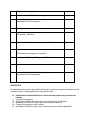
5
AC Fundamentals
10
13
1
1
6
Passive components
18
13
1
1
7
Switches and Relays
10
13
1
1
8
PCBs
8
8
1
1/2
9
Semiconductor Diode
6
8
1
1/2
10
Power supplies
12
13
1
1
120
110
10
8
Total
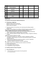
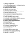
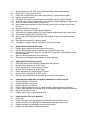
OBJECTIVES
On completion of the course the student should be able to
1.0 Comprehend the basic Principles of Electricity
1.1
1.2
1.3
1.4
1.5
1.6
1.7
1.8
1.9
1.10
1.11
1.12
1.13
1.14
1.15
1.16
1.17
1.18
1.19
1.20
1.21
1.22
1.23
1.24
Explain the concept of Electric current , Potential difference , Voltage and emf.
Distinguish between conductor, insulator and semi-conductor with respect
to valence electrons.
Explain the concept of a circuit State Ohm’s Law
Explain ohms law and its limitations.
Give the concept of Resistance to flow of electrons,
Define the terms specific resistance and conductivity.
Deduce the relation R =( l ) / a
Solve simple problems based upon the above formula.
Explain the effects of temperature on resistance
Define temperature co- efficient of resistance.
Derive the formula Rt = Ro (1+ost) to find resistance at any given temperature
Solve Simple problems using the above formula.
Explain series and parallel connections of Resistances
Derive the expressions for equivalent resistance for series and parallel connections.
Solve simple problems on series and parallel circuits
Explain the division of current in parallel circuits
Solve simple problems on the above.
List the effects of Electric current
Explain the Heating effect of Electric current
Derive expression for conversion of Electrical energy into equivalent heat energy in kilo Calories
(joules Law)
Define thermal efficiency
Solve problems on Electrical heating
Mention the practical applications of Electric heating like, Water heater, Electric Iron etc.
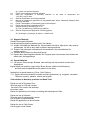
2.0 Know the magnetic effects of Electric Current
2.1
2.2
2.3
2.4
2.5
2.6
2.7
2.8
2.9
2.10
2.11
2.12
State coulombs laws of magnetism.
Define the terms Absolute and relative permeability of medium.
Explain the concept of lines of force & magnetic Field.
Define field intensity, Magnetic potential, Flux , Flux density .
Give the relation between Absolute and relative permeabilty
Draw and explain the field patterns due to
a. Straight current carrying conductor
b. Solenoid and
c. Toroid.
Explain Work law and its applications
State Laplace law (Biot-Savart’s Law)
Give expressions for field strength,
Develop the expression for magnitude of the force on a conductor in a magnetic field
State the Flemming’s left hand rule
Give the expression for the force between two
2.13
2.14
2.15
2.16
2.17
2.18
2.19
2.20
2.21
2.22
2.23
2.24
2.25
2.26
2.27
2.28
2.29
2.30
2.31
2.32
parallel current carrying conductors
State the nature of the force with different directions of the currents
Define ampere
Develop the concept of the Magnetic circuits
Define magneto motive force (mmf), permeability, flux and Reluctance
Solve problems on simple magnetic circuits
Compare magnetic circuit with electric circuit
Explain the terms leakage flux and leakage co-efficient
State Faraday’s laws of electro - magnetic induction
Explain dynamically and statically induced E.M.F.
State Lenz’s law and explain Flemming’s right hand rule
Develop the concept of self and mutual inductance
Derive the expressions for self and mutual inductances
State co-efficient of coupling
Explain the total inductance with series connections
with reference to direction of flux.
Give the equation for the energy stored per unit volume in a magnetic field.
Calculate energy stored per unit volume
Give the expression for lifting power of a magnet.
Solve problems on the above.
3.0 Understand Electric Charge and Electrostatic Field
3.1
3.2
3.3
3.4
3.5
3.6
3.7
3.8
3.9
3.10
3.11
3.12
3.13
3.14
3.15
3.16
3.17
3.18
State Coulomb’s law of electrostatics and define unit charge
Define absolute and relative permittivity.
Solve problems on the above
Explain electrostatic field.
Compare electrostatic and magnetic fields
State field intensity
State Gauss theorem
Explain electric potential and potential difference
Explain di-electric strength and di-electric constant
Give the Permitivity of commonly used die- electric materials
State unit of capacitance
Derive the formula for capacitance of a parallel plate capacitor
Explain equivalent capacitance of
Capacitors connected in series;
Capacitors connected in parallel
Explain charging and discharging of capacitor.
Give the expression for energy stored in a capacitor
Solve simple problems on the above
4.0 Chemical effects of Current and Batteries
4.1
4.2
4.3
Expalin Faradays laws of Electrolysis
Explain Polarisation or Back emf
Expain how the value of Back emf can be determined
4.4
4.5
4.6
4.7
4.8
4.9
4.10
4.11
4.12
4.13
4.14
4.15
4.16
4.17
4.18
4.19
4.20
Define Primary and Secondary Cells.
Explain the constructional details of a Lead acid Battery
List the active materials used in the construction of lead acid Battery
Explain the chemical reactions that take place during Charging and discharging
Explain the significance of internal resistance of a Battery
Define the two Efficiencies of the cell.
Draw the Electrical characteristics of Lead acid cell and explain.
Explain the condition of a Fully charged cell.
List the six important applications of Lead acid batteries
Explain constant current and Constant Voltage methods of Charging Lead acid batteries.
Solve simple problems to find charging current requirements
Explain the need for Trickle charging
Explain the sulphation and prevention
List the precautions to be observed to maintain the lead acid batteries.
List other types of Batteries used in Electronic Industry
Mention their applications
Compare Primary and Secondary cells.
5.0 Comprehend Vector representation of Alternating quantities.
5.1
5.2
5.3
5.4
5.5
5.6
5.7
5.8
5.9
5.10
5.11
5.12
5.13
5.14
Represent vector diagrams of sine waves of same frequency.
Perform addition and subtraction of alternating quantities using vector method.
Solve problems to find resultant vector of several alternating quantities.
Explain the effect of AC flowing through Pure Resistance , Inductance and Capacitance with
vector diagrams.
Explain mathematical representation of vectors in a) symbolic notation ,b) trigonometric c)
exponential and polar forms
Solve simple problems using J notation.
Define the terms Inductive reactance, Impedance, admittance, conductance and Power Factor
Explain Active and Reactive components of AC current
Explain Active and Reactive and apparent power in a AC circuit.
Define Q factor of a coil.
Explain power in an iron cored choking coil.
Explain AC through Resistance and capacitance connected in series.
Solve problems on RC series circuits.
Explain dielectric loss and Q factor of a Capacitor.
6.0 Understand passive components
6.1
6.2
6.3
6.4
6.5
6.6
6.7
6.8
6.9
6.10
Classify types of resistors.
List the specifications of a resistor, and state their importance.
Explain the necessity of preferred values in resistor.
Identify Resistance Value by using Colour Code.
Compare the features of carbon film metal film (thick and thin) and wire wound resistors with
respect to size, power rating, tolerance, temperature coefficient (PTC, NTC) and applications
Describe constructional details of carbon and wire wound potentiometers.
Compare the features of carbon and wire wound potentiometers
Mention the need for tapering in potentiometers.
Describe the working of rheostat and mention its application.
Explain the effects of temperature on resistance and define temperature co-efficient of resistance.
6.11
6.12
6.13
6.14
6.15
Understand the formula for resistance at any temperature
Rt = R0 (1+ o t)
Solve problems based on the above formula.
Describe the working of thermistor and sensistor and mention their applications.
List the common faults in resistors.
Familiarise with different types of inductors used in electronic circuit and their applications
6.16 Classify inductors.
6.17 Draw the symbol of different types of inductors
6.18 List the specifications of inductors.
6.19 List and Explain the important parameters of Air cored inductors
6.20 Explain the terms Stray inductance and stray capacitance
6.21 List various core materials used in the construction of inductors
6.22 Describe the constructional features
6.23 List the applications of A.F. and R.F chokes.
6.24 List the common faults in inductors
6.25 Explain the use of Ferrites in the construction of high frequency inductors
Familiarise with different types of capacitors used in electronic circuits and their
applications
6.26 Define the term capacitance.
6.27 Classify the types of capacitors.
6.28 List the specifications of a capacitor and state their importance.
6.29 Identify capacitor value by using colour code.
6.30 State the factors affecting the capacitance of a capacitor.
6.31 Define Di-electric constant and Di-electric strength of a material.
6.32 State the properties, range of values and applications of paper, mica, glass, polyester,
polystyrene, ceramic (different types) and electrolytic (different types) capacitors.
6.33 State different types of variable capacitors and mention their applications.
6.34 State losses in capacitors.
6.35 List the common faults in capacitors.
7.0 Familiarise with different types of switches, Connectors and Relays.
7.1
7.2
7.3
7.4
7.5
7.6
7.7
7.8
7.9
7.10
7.11
7.12
7.13
7.14
7.15
Explain the working of a switch.
Classify switches according to poles and throws (SPST, SPDT, DPST, DPDT, Multi-pole multithrow)
Explain the working of toggle, push button, rotary, slider, keyboard, and thumb wheel switches
with a mention to their ratings and applications.
Sketch the I.S.I symbols of various switches.
State the need of fuse in electronic equipment.
Mention different types of fuses.
Mention significance of ratings of fuse.
Explain the necessity of connectors in electronic circuits.
List different types of connectors.
Mention the use of MCB.
Define a relay.
Classify different relays based on principle of operation, polarization and application.
Mention specifications and applications of relays.
Explain the construction & working of general-purpose electromagnetic relay.
Explain the performance characteristics of relay.
7.16
List the contact materials used in relays and list their characteristics.
8.0 Comprehend PCB materials and their fabrication
8.1
8.2
8.3
8.4
8.5
8.6
8.7
8.8
8.9
8.10
8.11
8.12
8.13
8.14
9.0
Explain the need of PCB in electronic equipment.
Classify PCBs.
List types of laminates used in PCBs.
Mention the methods of layout preparation of PCB.
List the methods of transferring layout on the copper clad sheet.
List the steps involved in screen-printing for making PCBs.
List the materials used in screen-printing.
Describe the photo processing techniques for PCB preparation.
Mention the methods of etching, cleaning and drilling of PCB.
Describe the steps involved in making double-sided PCB.
List the materials used in soldering.
List the soldering methods of PCBs.
State the standard PCB specification.
Prepare a simple layout for a given circuit
Semiconductor Diodes
9.1
9.2
9.3
9.4
9.5
9.6
9.7
9.8
9.9
9.10
9.11
9.12
9.13
State the electrical properties of solid Semiconductor materials.
Sketch energy level diagrams for conductors, Semiconductors, Insulators.
Distinguish between Intrinsic and extrinsic Semiconductors.
Describe the formation of P type and N type materials and sketch the energy band diagrams.
Identify Majority and Minority carriers in P and N Type materials.
Distinguish between Drift and Diffusion current.
Explain the formation of PN junction diode.
Describe the working of PN junction Diode with various biasing voltages.
Sketch the forward/Reverse Bias Voltage characteristics of diode.
Interpret the manufacturer specifications of a given diode from data sheet.
Describe the formation and working of Zener diode.
Sketch the characteristics of Zener breakdown and Avalanche breakdown.
Distinguish between Zener breakdown and Avalanche breakdown.
10.0 DC Power Supplies
10.1 Explain the necessity of D.C. power supply for Electronic circuits.
10.2 Describe the working of HW, FW and Bridge section circuits with wave forms
10.3 Give the equations for RMS value, average DC value; ripple factor and efficiency for the above
10.4
10.5
10.6
10.7
10.8
Note:
circuits.
Define Voltage Regulation.
Explain the need for a filter circuit in power supplies.
Explain the operation of a rectifier circuit using RC, CRC, CLC filters.
State the need for a regulated power supply and list its specifications.
Explain the working of a simple Zener regulated DC Power supply.
Emphasis to be given to practice drawing Component symbols and circuits.
COURSE CONTENTS
1. Concept of DC Voltage and Current , - Conductor, Insulators -– Ohm’s law – Resistance – Specific
Resistance – Conductivity – Temperature coefficient of Resistance – Resistance in series, parallel
and series - parallel combinations – star/ delta equivalence
Units - Work - Power - Energy
Units of work, power and energy. – Conversion of Units Heating Effects of Electrical Current
Mechanical Equivalent of Heat - Heat produced due to flow of current in resistance- applications
2.Magnetic Effects of Electric Current
Magnetic materials.- Soft & Hard - Magnetic materials classification- Lines of force - Field pattern due
to long straight current carrying conductor-Field pattern of solenoid and Toroid -Work Law and its
applications -Biot Savart Law(Laplace Law) -Field strength at centre and any point on the axis of a
circular current carrying conductor- Field Strength around a straight current carrying conductorFleming’s left hand rule -Force between two parallel current carrying conductors – Ampere Magnetic circuit- Magnetising force – permeability - flux - reluctance - Magnetisation of Magnetic
materials Comparison of Magnetic circuit with electric circuit
Electro Magnetic Induction
Faraday’s laws - Dynamically and statically induced E.M.F -Lenz’s Law & Fleming’s right hand rule Self and mutual inductance - Co-efficient of coupling - Inductances in series -Energy stored in a
magnetic field - Energy stored per unit volume - Lifting power of magnet .
3.Electrostatics
Atom,Ion,positive and Negative charges -Laws of Electrostatics – coulomb - Permittivity - Electrostatic
induction -Electrostatic field - lines of force -Comparison of electrostatic and magnetic lines of force Strength of electric field- Flux density -Gauss theorem - Electric potential - potential difference –
Polarisation - Dielectric Loss - Applications of Dielectrics –
Dielectric strength - dielectric constant - Capacitance -Capacitor - types - Capacitors in series and
parallel
4.Chemical effects of electric current
Faradays laws of electrolysis- Polarisation –Construction of lead acid batteries- Charging and
Discharging of lead acid battery-Internal Resistance- AH efficiency & WH efficiency-Lead acid
battery characteristics-Charging of lead acid battery –trickle charging – Maintenance –Battery
types - Applications
5 AC Fundamentals : AC current Frequency , Time Period , Amplitude , RMS value and phase angle
AC through Resistance , Inductance , capacitance - concept reactance ,impedance and admittance,
6.Passive components
Resistors: Classification of resistors, colour code, Specifications, preferred values of resistors, their
properties and uses – Carbon film metal film wire wound resistors, characteristics and applications.
Constructional details of carbon and wire wound Potentiometers - tapering. Effect of temperature on
resistance. Thermistors, sensistors, faults in resistors.
Capacitors: Classification, specifications of capacitors, colour code, dielectric constant, dielectric
strength, properties and applications of paper, mica, ceramic polyester, polyesterene, glass and
electrolytic capacitors. Variable capacitors and applications, capacitor connected in series and
parallel. Energy stored in capacitors.
Inductors and Transformers: Self Inductance, mutual inductance, coefficient of coupling, A.F. and
R.F. chokes, transformers, auto transformers and specifications.
7. Switches, connectors and Relays: Different types of switches and connectors used in Electronic
circuits, their specifications, constructional details and ratings. Fuses. Types of relays-Relay contacts,
constructional features of relays.
8. PCBs: Classification of PCBs, screen-printing of PCBs, photo processing, double sided PCBs,
soldering methods of PCBs, standard PCB specifications.
9. Semiconductor diodes: Electrical properties of semiconductor materials, energy level diagrams of
conductor, semi conductor and Insulator. Formation of P-Type and N-Type materials and their
properties. Drift and diffusion current. Formation and behaviour of PN junction diode.- Zener diodezener breakdown and avalanche breakdown
10. DC Power supplies
Need of DC power supply, half wave, full wave and bridge rectifiers. RMS value, ripple factor, voltage
regulation. Filters – RC, CRC, and CLC. Zener regulator – series and shunt. IC regulators and
specifications of RPS
TEXTBOOKS
1. Electronic devices and applications by B. Somanathan Nair, PHI.
2. Electronic components by
Dr.K.Padmanabham.
3. Electronic Instruments and Systems by B.P Gupta TMH
REFERENCE BOOKS
1.
2.
3.
4.
5.
P.C.Bs
by
Boshart
Basic Electronics
by
Grob.
Electronic devices & Circuits by Millman & Halkias
Fundamentals of Accoustics by Lawrence & Frag.
Electronic Components
by F.J. Waters.
EC-106
TMH
TMH
TMH
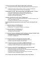
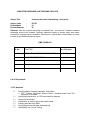
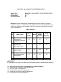
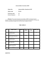
ELECTRICAL AND ELECTRONICS ENGINEERING MATERIALS AND
PRACTICES
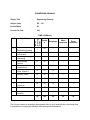
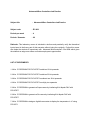
Subject Title:Electrical and Electronics Engineering Materials & Practices
Subject Code: EC-106
Periods/Week: 04
Periods/year: 120
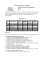
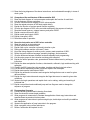
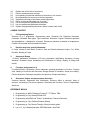
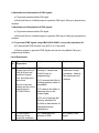
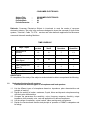
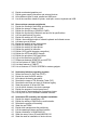
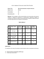
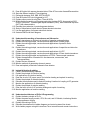
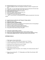
Time Shedule
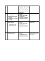
S
No
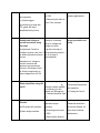
1
2
3
Major topics
Classification of materials and
properties of conductors
Properties and applications of
Insulating materials
Properties and applications of
No of
periods
20
Weightage of
marks
16
Short answer
questions
20
16
2
2
20
13
1
Essay
questions
1
1
1
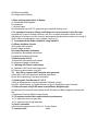
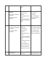
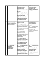
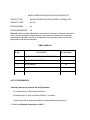
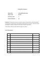
4
5
6
7
8
9
10
magnetic materials
Properties and applications of
Special materials
Introduction to Workshop
processes
Important machines used in the
wotkshops
Fastening
Sodering Brazing and Welding
Heat treatment
Electrical hazards- First Aid and
safety
total
12
13
1
1
12
13
1
1
12
13
1
1
12
13
1
1
12
13
1
1
120
110
10
8
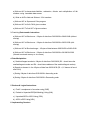
OBJECTIVES.
On completion of the study the student will be able to
1.0 Classification of Materials
Explain the atomic structure of the atom
Explain the electronic structure of the atom
Explain energy band diagram
1.1 Classify the material into conducting, semi conducting and insulating materials
energy bands
1.2 Explain how the resistance of a conductor is affected by presence of impurities 1.3
Classify the conducting material as low resistivity and high resistivity materials
List the 4 Metals commonly used in Electrical and Electronics fields .
1.4 Define Mechanical properties density,stress,strain,strength,ductility,hardness,wear
impact resistance,fracture toughness,fatigue of conductors
1.5 List the Electrical properties of Copper (conductivity, resistivity, temperature coefficient)
of copper.
Explain the mechanical properties of copper
1.6 Explain general properties like conductivity, resistivity, temperature coefficient,
solderability, contact resistance of aluminium and mechanical properties of hard and
annealed aluminium.
1.7 Explain general properties like conductivity, resistivity, corrosion, temperature
Coefficient and mechanical properties of Steel.
1.8 Application of different conductors in electronics engineering,.
1.9
1.12 Define corrosion,list four methods to prevent corrosion of conductors.
1.13 Define superconductivity.
1.14 List two types of super conductors.
1.15 List applications of super conductors.
2.0 Insulating materials; General Properties:
2.1 8.0 Insulating Materials.
8.1
State the important electrical properties of Insulating materials.
(a) Insulating resistance
8.2
8.3
8.4
8.5
8.6
8.7
8.8
8.10
(b) Volume and Surface resistance
Explain factors affecting insulating resistance.
State the classification of Insulating materials on the basis of temperature like
Y,A,E,B,F,H and C class.
State the classification of insulating materials.
Mention the properties & applications of Impregnated paper, Wood, Cardboard, Asbestos, Mica,
Ceramics and Glass.
Explain Thermoplastic & Thermosetting resins with examples.
Explain the properties & applications of PVC
State the effects of the following on P.V.C
(a) Filler (b) Stabilizer (c) Plasticizer (d) Additives.
State the Properties and application of following gasses.
Air (b) Nitrogen (c) Hydrogen (d) Sulphur – HexaFluoride
3.0 Magnetic Materials
Classify the magnetic Materials
List the important magnetic materials used in the industry
3.2 Explain Soft Magnetic Materials like Alloyed steels with silicon, high silicon, alloy steel for
transformers, low silicon alloy steel for electric rotating machines.
3.3 Explain Cold rolled grain oriented steels for transformer, Non-oriented steels for
rotating machine
3.4 Describe about Nickel-iron alloys,Soft ferrites
3.5 Explain about Hard magnetic materials like Tungsten steel, chrome steel, hard ferrites and
cobalt steel, their applications
4.0 Special Materials
4.1 List various Thermocouple, Bimetals, lead soldering and fuse material, mention their
Applications
Explain about low resistivity copper alloys: Brass, Bronze (cadmium and Beryllium),
and their practical applications with reasons for the same.
Applications of special metals e.g. Silver, Gold, Platinum .
1.11 Explain about high resistivity materials and their applications e.g., manganin, constantin,
Nichrome, mercury, platinum, carbon and tungsten
5.Introduction to Workshop practices and Hand Tools
.
Explain the use of Engineers Files
Show the parts of a file with a sketch.
list various Files used in the workshop
Know their usage.
Explain the precautions to be taken in handling and maintenance of files.
Explain the use of Hacksaw
Show the parts of hacksaw with a sketch.
List the types of Hacksaw blades .
Explain the applications of above blades.
Explain the use of Cold Chisels
List the types of cold chilsels
List the types of hammers.
Explain the parts of Ballpein hammer with a sketch.
Explain the use of Screwdrivers .
List the types of Screw Drivers used in the workshop.
Explain the use of Taps and Dies
Cutting tools and Cutting Fluids
List the 3 important properties a) Red hardness b) Abrasion Resistance, c) Toughness of
cutting tools.
Explain the above properties.
List the 6 important types of Cutting tool materials.
Explain the use of 1. High speed steels 2. Stelite 3.Cemented carbide 4. Ceramic 5. Cubic
Boron nitride 6. Diamond. For cutting tools.
Explain the need for cutting fluids
List the 5 types of cutting fluids
Mention the precautions to be taken while handling cutting fluids.
6. Machines Used in the workshop
List the % important Operations Used in the workshop . 1. Drilling 2. Turning . 3. Grinding . 4.
Milling
Name the machines used to carry out the above operations.
Name the various parts of a drilling machine and mention their purpose.
With a sketch explain the Drill chuck and safety chuck key
List the cutting tools usede with drilling machine.
Explain the use of twist drill and Reamer.
Explain Countersunk and Counterbore operations
.Explain how sheetmetal drilling is carried out.
Explain How Plastic drilling is carried out.
Explain the process of Turning.
List the parts of Centre Lathe machine.
Explain the parts of Centre Lathe machine.and their functions.
Explain the constructional details of 3 jaw self centring and 4 Jaw Independent chuck
Explain the use of Face plate.
List the 6 important operations of lathe machine .
Explain the operations 1. Turning 2. Drilling 3. Reaming 4. Boring 5. Taper turning.6. Thread
cutting
Explain the purpose of grinding.
List the parts of surface grinding machine
Explain the functions of above.
Explain how Grinding wheels are made.
Explain the terms Dressing ,Balancing and Guarding with respect to Grinding wheels.
Mention the two Abrasive materials used for grinding wheels.and explain the importance ofr
grain size.and grade.
Explain the milling operation.
List the Three types of Milling machines.
List the parts of Milling machines with a sketch.
Mention the purpose of above parts.
7.Mechanical Fasteners
List the Four types of Mechanical Fasteners 1. Screws Bolts , Nuts and Rivets.
Classify machine screws based on the types of screw Head
Explain the use of Socket screws and Self tapping screws
Explain the use of Bolts anjd Nuts
List different types of Nuts used in the industry.
Explain the Purpose of washers
List different types of screw threads
Explain the use of Self locking screws and Bolts.
Explain the use of locking Nuts
Explain threadlocking.
Expalin the use of Locking washers.
Mention the 4 types of Locking washers. And circlips.
Explain the process of Riveting
Mention any 4 advantages of Riveting
Mention the applications of Rivets.
List the metals used for riveting
Explain solid Rivets , Tubular rivets and self piercing rivets
Explain the use of Blind rivets.
Explain how electrical connections are secured using mechanical fastening devices
Explain the use of Bullet connector for Automobile Electrical connections.
Explain the use of Adhesives for joining
Explain the advantages of joining parts by using adhesives
Mention the demerits of adhesives.
Classify adhesives
Explain the use of Thermoplastic Resins.
Explain the use of cyanoacrylate (Superglue)
Explain Thermosetting Resins
Explain the use of Epoxys
8.Soldering , Brazing and Welding
Explain the process of soft soldering.
Expalin the use of flux in soldering
Explain the Heating requirements in the soldering process.
List three types of soldering joints for joining Electrical conductors.
Explain the metals and their mix ratios used in producing solder alloys.
Explain Eutectic point of metals.
Mention the Tin Lead ratios for a) general purpose Electrical soldering b) Plumber solder and
dipping baths.
Explain the process of Brazing.
Explain alloys used for brazing. brass and Silver Brazing
Explain the purpose of flux in Brazing.
Name the Fluxes used in Brazing
Mention heat sources suitable for brazing
With a sketch explain the joint designs suitable for brazing
List any 4 applications of Brazing.
Explain the process of welding
Mention the two types of Welding
Expalin the process of Arc Welding
Explain the Process of Gas welding.
Mention the applications of Arc and Gas welding.
9. Heat treatment of Steel
Explain the Process of Heat treatment.
List the desirable mechanical properties of steel
Explain the properties , Hardness , Brittleness , Strength, Ductility,
Malleabilty
Elasticity and toughness
With a Graph explain the relation between Critical temperature and carbon content
Explain the process of annealing
Explain the process of Normalizing
Explain the process of Hardening
Explain the process of Tempering .
Give the table showing Tempering temperatures and oxide colours.
10.0 Electrical Hazards – First aid and Safety
Explain the importance of safety in the industry.
8.1 Explain the major hazards which may arise from the use of electrical
equipment
8.2 Explain the precautions to be taken to prevent accidents while using
Machines
Explain how human body may act as a part of the circuit and cause Electrical shock
8.3 Explain method of first aid treatement for someone suffering from electric shock.
8.4 State general electrical safety rules
Explain the safety signs and colours
Show various safety symbols and Explain their meaning.
Explain the causes of ire and fire accidents in industry.
Explain Fire prevention measures.
List 6 types of Portable fire extuinuishers
Explain the choice of above extuinguishers.
Explain the First aid treatment in the case of burns
Course Content
1 Classification of materials
Classification of materials into conducting, semiconducting and insulating materials. Conducting
Materials: Resistivity and factors affecting resistivity, such as temperature, alloying. Low resistivity
materials e.g. copper, aluminum and steel, their general properties as conductor e.g. resistivity,
temperature co-efficient, mechanical properties, corrosion, solar ability, contact resistance and
practical application. High resistivity materials.Super conductors.
2 Insulating Materials
Properties of insulating material:- Electrical properties, Mechanical properties, Physical properties,
Thermal properties, Chemical properties, Insulating materials and their application-Definition and
classification of Thermo setting materials e.g. Phenol Formaldehyde, Resins (i.e. Bakelite),
Thermo Plastic materials e.g. Polyvinyl Chloride (P.V.C.), ,Natural Insulating Materials- Mica and
Asbestos ,Gaseous Materials e.g. Air, Hydrogen and SF6. (8 Lectures
3 Magnetic Materials:
B-H curve of magnetic materials, Classification of magnetic materials into soft and hard magnetic
materials. Soft magnetic materials - high silicon alloy steel for transformers and low silicon alloy
steel, for electric rotating machine cold rolled grain oriented and non-oriented steel, Nickel iron
alloy, soft ferrites, their properties and uses. Hard magnetic materials - tungsten steel, chrome
steel, cobalt steel, alnico, hard ferrites, their properties and applications. (8 Lectures)
4 Special Purpose Materials:
Thermocouple, bimetals, leads soldering and fuses material, mention their applications,
Introduction of various engineering materials necessary for fabrication of electrical machines such
as motors, generators, transformers etc.
6. Tools and their uses
Dfferent files,hacksaw,hammers,screwdrivers,drillers and grinders used in electronic industry
7.Joining Methods:
Mechanical fasteners,soldering,brazing,welding,adhesive bonding. Application of each method.
Comparision of different methods.
8. Electrical hazards - first aid and safety
Electric shock,electric burn,fire,arcing,explosion .Double insulation , earthing,use of safe voltages
Electric shock and treatement,General electrical safety rules.
RECOMMENDED BOOKS
1.Material science for Electrical and Electronic engineers by Ian p.Jones
2. Workshop processes, practices and Materials by Bruce J. Black
3. Electrical and Electronic Engineering Materials by SK Bhattacharya, Khanna Publishers,New
Delhi
4. Electronic Components and Materials by Grover and Jamwal, Dhanpat Rai and Co.,
NewDelhi
5. Electrical Engineering Materials by Sahdev, Unique International Publications
6. Electronic Components and Materials by SM Dhir, Tata Mc Graw Hill, New Delhi
7. Electronic Engineering Materials by ML Gupta, Dhanpat Rai & Sons, New Delhi
8. Electrical Engineering Materials by PL Kapoor, Khanna Publishers, New Delhi
9. Electrical & Electronics Engineering Materials by BR Sharma and Others, Satya Parkashan,
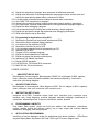
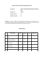
ENGINEERING DRAWING
Subject Title
:
Engineering Drawing
Subject Code
:
EC – 107
Periods/Week
:
06
Periods Per Year
:
180
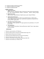
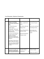
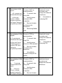
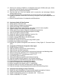
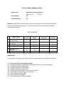
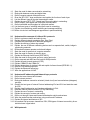
TIME SCHEDULE
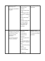
Major Topics
No. of
Drawing
plates
S.No
Period
s
Weightage
Short
Questions
--
03
-
-
-
01
03
-
-
-
01
06
5
1
-
01
09
5
1
-
03
21
15
1
1
03
21
10
-
1
01
06
5
1
-
Essay
Questions
7
Importance of
Engineering Drawing
Engineering Drawing
Instruments
Free hand lettering &
Numbering
Dimensioning
Practice
Geometrical
constructions
Projection of points,
Lines, Planes &
Auxiliary
Solids views
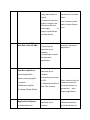
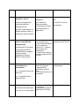
8
Sectional views
04
27
10
-
1
9
Orthographic
Projection
Pictorial drawing
04
33
10
-
1
04
30
10
-
1
Development of
surfaces
Total
03
21
10
-
1
25
180
80
04
06
1
2
3
4
5
6
10
11
The Course is aimed at developing basic graphic skills so as to enable them to use these skills
in preparation of engineering drawings, their reading and interpretation
Pre-Requisite: Clear visualization and sound pictorial intelligence
OBJECTIVES
Upon completion of this subject the student shall be able to
1. Understand the basic concepts of Engineering Drawing
1.1
State the importance of drawing as an engineering communication medium.
1.2
State the necessity of I.S. Code of practice for Engineering Drawing.
1.3
Explain the linkages between Engineering drawing and other subjects of
study in diploma course.
2.0
Use of Engineering Drawing Instruments (No. of drawing plates: 01)
2.1
Select the correct instruments and draw lines of different orientation.
2.2
Select the correct instruments and draw small and large Circles.
2.3
Select the correct instruments for measuring distances on the drawing.
2.4
Use correct grade of pencil for different types of lines, thickness and given
function.
2.5
Select and use appropriate scales for a given application.
2.6
Identify different drawing sheet sizes as per I.S. and Standard Lay-outs.
2.7
Prepare Title block as per I.S. Specifications.
2.8
Identify the steps to be taken to keep the drawing clean and tidy.
Drawing Plate 1: (Having two exercises)
3.0
Write Free Hand Lettering and Numbers (No. of drawing plates: 01)
3.1
Write titles using sloping lettering and numerals as per B.I.S (Bureau of Indian
standards)
3.2
Write titles using vertical lettering and numerals as per B.I.S.
3.3
Select suitable sizes of lettering for different layouts and applications.
3.4
Practice the use of lettering stencils.
Drawing plate 2: (Having 5 to 6 exercises)
4.0
Understand Dimensioning Practice (No. of drawing plates: 01)
4.1
State the need of dimensioning the drawing according to accepted
standard.
4.2
Define “Dimensioning”.
4.3
Identify notations of Dimensioning used in dimensioned drawing.
4.4
Identify the system of placement of dimensions in the given
dimensioned drawing.
4.5
Dimension a given drawing using standard notations and desired
system of dimensioning.
4.6
Dimension standard features applying necessary rules.
4.7
Arrange dimensions in a desired method given in a drawing.
4.8
Identify the departures if any made in the given dimensioned drawing
with reference to SP-46-1988, and dimension the same correctly.
Drawing Plate 3: (Having 08 to10 exercises)
5.0
Apply Principles of Geometric Constructions
(No. of drawing plates: 03)
5.1
Divide a given line into desired number of equal parts internally.
5.2
Draw tangent lines and arcs.
5.3
General method to construct any polygon.
5.4
Introduction to conics
5.5
Construction of ellipse, parabola and hyperbola by general method
5.5
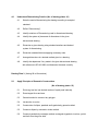
Construct ellipse by concentric circles method
5.6
Construct parabola by rectangle method, rectangular hyperbola, involute, cycloid
and helix from the given data.
5.7
State the applications of the above constructions in egineering practice.
Drawing Plate -4: Draw one plate having problems up to construction polygon
Drawing Plate -5: Draw one plate having problems of construction of conics
Drawing Plate -6: Draw one plate having problems of construction of involute, cycloid
and helix
6.0
Apply Principles of Projection of points, lines, planes & solids
(No. of Drawing Plate: 03)
6.1
Visualize the objects
6.2
Introduction to I-angle and III-angle projections
6.3
Draw the projection of a point with respect to reference planes (HP
& VP)
6.4
Draw the projections of straight lines with respect to two references
Planes (up to lines parallel to one plane and inclined to other plane)
6.5
Draw the projections of planes (up to planes perpendicular to one plane and
inclined to other plane)
6.6
Draw the projections of solids (up to axis of solids paralle to one plane and
inclined to other plane)
Drawing Plate -7: Draw one plate having problems up to projection of points and
Lines (15 exercises)
Drawing Plate -8: Draw one plate having problems of projection of planes
(6 exercises)
Drawing Plate -9&10: Draw Two plates having problems of projection of solids
(total 10 exercises)
7.0
Understand the need for auxiliary views
7.1
State the need of Auxiliary views for a given engineering drawing.
7.2
Draw the auxiliary views of a given engineering component
7.3
Differentiate between auxiliary view and apparent view
Drawing plate No.11: (Having 4 exercises)
8.0
Appreciate the need of Sectional Views
8.1
Explain the need to draw sectional views.
8.2
Select the section plane for a given component to reveal maximum
information.
8.3
Explain the positions of section plane with reference planes
8.4
Differentiate between true shape and apparent shape of section
8.5
Draw sectional views and true sections of regular solids discussed in 6.0
8.6
Apply principles of hatching.
Drawing Plate – 12: Draw one plate having problems of section of solids
.
(6 exercises)
9.0
Apply principles of orthographic projection (No. of plates: 04)
9.1 Explain the principles of orthographic projection with simple sketches.
9.2 Prepare an Engineering drawing of a given simple engineering part
in first angle projection.
9.3 Draw the orthographic view of an object from its pictorial drawing.
9.4 Draw the minimum number of views needed to represent a given object fully.
Drawing Plate 13 : (Having 10 to 12 exercises)
10.0
Prepare pictorial drawings
10.1
State the need of pictorial drawings.
10.2
Differentiate between isometric scale and true scale.
10.3
Prepare Isometric views for the given orthographic drawings.
Drawing plate 14: (Having 10 to 12 exercises)
11.0
Interpret Development of surfaces of different solids
11.1
State the need for preparing development drawing.
11.2
Prepare development of simple engineering objects using parallel line
and radial line method.
11.3
Prepare development of surface of engineering components like trays, funnel, 90 0
elbow & rectangular duct.
Drawing plate No. 15: (Having 10 exercises)
KEY competencies to be achieved by the student
S.No
List of Practical
1.
Importance of Engineering Drawing
2.
Engineering Drawing Instruments
3.
Free hand lettering & Numbering
4.
Dimensioning Practice
5.
Geometrical construction
6.
Projection of points, Lines, Planes & Solids
7.
Auxiliary views
Key Competency
8.
Sectional views
9.
Orthographic Projection
10.
Pictorial drawing
11.
Development of surfaces
Explain the linkages between Engineering
drawing and other subjects of study in
Diploma course.
Select the correct instruments to draw
various entities in different orientation
Write titles using sloping and vertical
lettering and numerals as per B.I.S
(Bureau of Indian standards)
Dimension a given drawing using
standard notations and desired system of
dimensioning
Construct ellipse, parabola, rectangular
hyperbola, involute, cycloid and helix from
the given data.
Draw the projection of a point, straight
lines, planes & solids with respect to
reference planes (HP& VP)
Draw the auxiliary views of a given
Engineering component
Differentiate between Auxiliary view and
apparent view
Differentiate between true shape and
apparent shape of section
Use conventional representation of
Engineering materials as per
latest B.I.S. Code.
Apply principles of hatching.
Draw simple sections of regular solids
Draw the minimum number of views
needed to represent a given object fully
Differentiate between isometric scale and
true scale.
Draw the isometric views of given
objects,.
Prepare development of Surface of
Engineering components like trays,
funnel, 900 elbow & rectangular duct.
COURSE CONTENT
NOTE
1.0
1.
I.S. / B.S Latest Specification should invariably be followed in all the topics.
2.
A-3 Size Drawing Sheets are to be used for all Drawing Practice Exercises.
The importance of Engineering Drawing
Explanation of the scope and objectives of the subject of Engineering Drawing Its
importance as a graphic communication -Need for preparing drawing as per standards –
SP-46 –1988 – Mention of I.S.O and B.I.S-Role of drawing in -engineering education –
Link between Engineering drawing and other subjects of study.
2.0
Engineering drawing Instruments
Classifications: Basic Tools, tools for drawing straight lines, tools for curved lines, tools
for measuring distances and special tools like mini drafter & drafting machine –
Mentioning of names under each classification and their brief description -Scales:
Recommended scales reduced & enlarged -Lines: Types of lines, selection of line
thickness - Selection of Pencils -Sheet Sizes: A0, A1, A2, A3, A4, A5, Layout of drawing
sheets in respect of A0, A1, A3 sizes, Sizes of the Title block and its contents - Care and
maintenance of Drawing Sheet, Drawing plate:
Lay out of sheet – as per SP-46-1988 to a suitable scale.
Simple Exercises on the use of Drawing Instruments. Importance of Title Block.
3.0
Free hand lettering & numbering
Importance of lettering – Types of lettering -Guide Lines for Lettering
Recommended sizes of letters & numbers - Advantages of single stroke or
simple style of lettering - Use of lettering stencils
4.0
Dimensioning practice
Purpose of engineering Drawing, need of I.S.I code in dimensioning -Shape
description of an Engineering object -Definition of Dimensioning size
description -Location of features, surface finish, fully dimensioned Drawing Notations or tools of dimensioning, dimension line extension line, leader line,
arrows, symbols, number and notes, rules to be observed in the use of above
tools -Placing dimensions: Aligned system and unidirectional system ( SP-461988)-Arrangement of dimensions Chain, parallel, combined progressive, and
dimensioning by co-ordinate methods-The rules for dimensioning standard,
features “Circles (holes) arcs, angles, tapers, chamfers, and dimension of
narrow spaces.
5.0
Geometric Construction
Division of a line: to divide a straight line into given number of equal parts
internally examples in engineering application.
Construction of tangent lines: to draw tangent lines touching circles
internally and externally.
Construction of tangent arcs
i) To draw tangent arc of given radius to touch two lines inclined at given
angle (acute, right and obtuse angles).
ii)Tangent arc of given radius touching a circle or an arc and a given line.
iii)Tangent arcs of radius R, touching two given circles internally and externally.
Construction of polygon:
construction of any regular polygon of given side length
using general method
Conical Curves: Explanation of Ellipse, Parabola, Hyperbola, as sections of a
double cone and a loci of a moving point, Eccentricity of above curves – Their
Engg. application viz. Projectiles, reflectors, P-V Diagram of a Hyperbolic process,
Construction of any conic section of given eccentricity by general method
Construction of ellipse by concentric circles method
Construction of parabola by rectangle method
Construction of rectangular hyperbola
General Curves: Involute, Cycloid and Helix, explanations as locus of a moving point,
their engineering application, viz, Gear tooth profile, screw threads, springs etc. – their
construction
6.0
Projection of points, lines and planes & solids
Projecting a point on two planes of projection -Projecting a point on three planes of
projection -Projection of straight line.
(a) Parallel to both the planes.
(b) Perpendicular to one of the planes.
(c) inclined to one plane and parallel to other planes
Projection of regular planes
(a) Plane perpendicular to HP and parallel to VP and vice versa.
(c) Plane perpendicular to HP and inclined to VP and vice versa.
Projection of regular solids
(a) Axis perpendicular to one of the planes
(b) Axis parallel to VP and inclined to HP and vice versa.
7.0
Auxiliary views
Need for drawing auxiliary views -Explanation of the basic principles of
drawing an auxiliary views explanation of reference plane and auxiliary plane Partial auxiliary view.
8.0
Sectional views
Need for drawing sectional views – what is a sectional view - Location of cutting plane –
Purpose of cutting plane line – Selection of cutting plane to give maximum information
(vertical and offset planes) - Hatching – Section of regular solids inclined to one plane
and parallel to other plane
9.0
Orthographic Projections
Meaning of orthographic projection -Using a viewing box and a model – Number of views
obtained on the six faces of the box, - Legible sketches of only 3 views for describing
object -Concept of front view, top view, and side view sketching these views for a
number of engg objects -Explanation of first angle projection. – Positioning of three
views in First angle projection Projection of points as a means of locating the
corners of the surfaces of an object – Use of miter line in drawing a third view when
other two views are given -Method of representing hidden lines -Selection of minimum
number of views to describe an object fully.
10.0
Pictorial Drawings
Brief description of different types of pictorial drawing viz., Isometric, oblique,
and perspective and their use - Isometric drawings: Iso axis, angle between
them, meaning of visual distortion in dimensions - Need for an isometric scale,
difference between Isometric scale, and ordinary scale difference between Isometric
view and Isometric projection - Isometric and non-Isometric lines -Isometric drawing of
common features like rectangles, circular - shapes, non-isometric lines - Use of
box and offset methods
11.0
Development of Surfaces
Need for preparing development of surface with reference to sheet metal work
-Concept of true length of a line with reference to its orthographic
projection when the line is (i) parallel to the plane of projection (ii) inclined to one
principal and parallel to the other -Development of simple solids like cubes, prisms,
cylinders, cones, pyramid (sketches only) -Types of development: Parallel line and radial
line development -Procedure of drawing development, drawings of trays funnels, 90 0
elbow pipes and rectangular ducts.
REFERENCES
1. Engineering Graphics by P I Varghese – ( McGraw-hill)
2. Engineering Drawing by Basant Agarwal & C.M Agarwal - ( McGraw-hill)
3. Engineering Drawing by N.D.Bhatt.
4. T.S.M. & S.S.M on “ Technical Drawing” prepared by T.T.T.I., Madras.
5. SP-46-1998 – Bureau of Indian Standards.
Electronic workshop
Subject title
: Electronic workshop
Subject code
Periods per week
:
:
EC-108
6
Periods / Semester
:
180
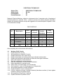
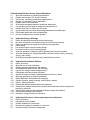
TIME SCHEDULE
Sl
NO
1
2
3
4
5
Major Topics
Periods
Identification of different Tools and Materials and their working
Identification of different wires, cables and House wiring
Soldering practice & Preparation of PCB
Study and use of Electronic equipment
Testing of Electronic components & characteristics
Total Periods
20
40
40
40
40
180
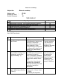
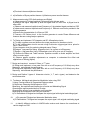
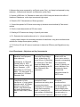
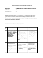
List of the Experiments
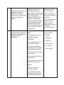
Exp
No
1
Name of the Experiment
Objectives
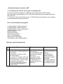
Key competencies
Know the safety precautions
and first aid
a) Take precautions
to prevent accidents
in the laboratory b)
Alerting under
emergency situations
c) Basic first aid.
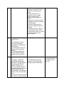
2
Cleaning the equipment and
Work Tables including Visual
inspection -reporting any
physical damage (3)
a) Precautions to be followed
in the laboratory ,(starting and
Stopping of equipment /
Machinery) b) symbols and
their meaning c) Clear
understanding of emergencies
, b) Sequence of actions to be
carried out c) basic first aid
procedure
Keeping work area clean
Familiarization with equipment
Procedure for cleaning
Use of Detergents, Shampoos
and solvents. Precautions to be
taken (use of masks, Gloves
etc)
Precautions to be taken a)
Handling the equipment b)
Personal (Washing hands with
soda after cleaning the
equipment)
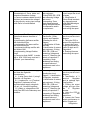
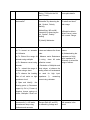
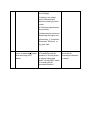
3
Identifying and practicing
with Measuring and Marking
Tools (3)
1Measuring Tape 2. Steel rule
3.Trysquare 4. Center Punch
5. Plumb
A) Handling the equipment
Should be able to
clean the equipment
with appropriate
cleaning agent.
Report any damage to
the power cords ,
missing fuses , Low
battery in DMMS etc.
B)Use the measuring tape to
measure a distance of 6 feet
and above accurately and
mark.
B) Use the steel rule to
measure an odd length
given in inches and in
millimeters accurately and
mark.
c) Use the Try square to mark
perpendicular lines by selecting
a finished edge.
d) Use the centre punch to
mark centre points as per the
drawing
e) Use the plumb to observe
1) inclination of wall ii) mark
two horizontal points on a wall
at a given height and at a
given distance.
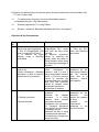
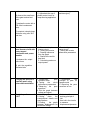
4
Working with different type of
screw Drivers .
(3)
a) Identifying 1. Screw
Driver a) b) Flat Head
Screwdrivers c) Ratcheting
Screwdrivers
b) Use the Screw Driver to
Remove and Fix wooden
Screws
C) Fixing and Removing
screws of Metal cabinets
using correct screw Driver
5
.Working With Basic tools
(6)
a) Identify 1.Hacksaw
frame/Blade 2. Ball peen
hammers 3. Sledge hammer.
4 Claw hammer 5 Anvil 6
Chisels 7. Bench vice
b) Fix the Hacksaw blade in
the frame and use it to cut a)
Conduit pipe b) Cut the
Wooden piece with hacksaw
frame by fixing it in the bench
vice.
c) Use a cold chisel to cut the
6mm Rod to required length.
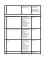
a) to identify and know the
usage b) To develop skills in
using the above instruments
Select Right tool for a
particular situation b)
Use the above tool
with skill
d) Use the sledge hammer to
bend a 6mm Rod into a ring
by striking it on the Anvil
e) Drive nails in to a wooden
piece with ball peen hammer.
f) Remove the Nails using
claw hammer
6
.Working with Tools used in
Electrical Wiring
(3)
A ) Identifying 1. wire
stripper . 2. Insulation
remover 3. Pocket knife
5.Electrical Tester 4.Phillips
Head Screwdrivers 5. Mallet
6. Rawl plug jumper 7
.Standard wire Gauge
b) Use the above tools to
remove the insulation.
c) Use the mallet to straighten
the cable/ Conductor
d) Measure the gauge of wire
using Standard Wire Gauge.
e) Make a hole in the wall for
fixing a Screw/ Nail using
Raw plug Jumper and ball
peen Hammer.
Identification of above tools,
know their purpose and usage
identifying the tools by
their shape and size
b) Identifying the tool
by their name . Select
correct tool for a
particular operation c)
measure the wire
Gauge d) Fix a screw
in the wall.
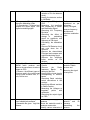
7
Working with different
fastening devices, spanners,
wrenches and Allen/ Hex
keys (3)
1. Identification of different
types of fastening devices like
Screws, Bolts and Nuts,
Rivets, and know their
specifications
b) Tightening the bolts and
nuts using correct type and
number of spanner a)
Normal b) Ring type ,
c) Use the Monkey Wrench
and Pie wrench to Tighten GI
pipe coupling
To identify various fastening
devices by their name and
shape
Know the usage and selection
of the tools
Use the fastening
devices
Use the tools.
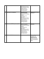
8
Identifying and Working with
Pliers (3)
a) Identify and Know the
various functions of cutting
pliers, Nose pliers, Pipe
pliers, Flush cutter, top
To identify various types of
{Pliers by their name and
shape
Know the usage and selection
of the tools
Use the suitable
pliers
For a given job
cutting pliers, Electronics
pliers, Insulated cutting
pliers
b) perform the following
operations 1. Holding 2. Wire
cutting 3. Component
bending 4. Twisting the wire
9
Working with Drilling Machine
. (3)
1. Identify the parts of Drilling
Machine and drill bits used
with hand drilling machine
b) Use the Hand drill to make
holes in the wood
c) use Electrical hand held
hammer drill to make holes in
the wall.
C . Identify Electrical drilling
machine and observe how
holes are made in Mild steel
Plates
Know the purpose and types of
drilling machines
Fix the drilling bit in the chuck
Safety precautions to be taken
Use the drilling
machine to make
holes
10
Identification of Grinding
machine 3.Lathe machine 4.
Milling machine 5. Blower. (3)
a) Identify Grinding machines
and observe its usage to
sharpen cutting tools and Drill
bits and for cutting operation
on metals.
b) Identify Lathe machine and
observe various operations
like turning , taper turning ,
Knurling , Boring Etc
c) Identify the milling machine
and Know its usage.
d) identify the Electric Blower
and use it for Removing dust
and cleaning
Identification of different5
machines and their use in the
workshop
Identify the machine
and its function.
11
Working with Adhesives (3)
a) Practice the use of
adhesives like Araldite ,
Feviquick, Fevicol, Mseal, to
join Non metals
b Using PVC cement to
join PVC Pipes
To know and practice joining
using different adhesives
Join the parts using
Araldite, Mseal etc.
Identifying conductors
Identify the Copper , aluminum
12
Know the use of adhesives in
Fixing components on PCBs
To identify conductors
insulating materials
semiconductors and magnetic
materials like
(1 ½)
1. Copper , Aluminum , Tin
,Solder Metal .
2. Plastics, Teflon, PVC,
glass, porcelain, ceramic
Bakelite, Mica, Paper, Cotton
sleeves, Prespahn sheet,
Transformer Oil. Etc
3. Carbon rods
4. Iron , Steel, Ferrites
, iron and other metals by
physical observation
Identify the Insulating materials
by their name and physical
observation
and Insulators
13
. Identification of different
wires and cables
(1 ½)
a)
Identifying different
wires and cables used in the
industry
1.Hookup wires a. PVC wire
b. Teflon wires c.single strand
d. multi strand
B) .Wires used for electrical
wiring
a) Service wire b..
TRS wires /PVC Wires (Al
and Cu)
c .single strand
d. Multi
strand e. twisted Flexible pair
wires f. Enameled copper
wire
B) 1. Power cord. 2. UTP
cables 4.Co axial cables 5.
Flat ribbon cable for antennas
6. 9.Telephone cable
10.Ethernet cable 11. Ribbon
cables 12 . Optical fiber
Knowing the technical names
of the wires
Knowing the gauge of the wire
Knowing the insulation used
and its purpose
Identifying the difference
between single strand and
Multistrand wire
Selecting a wire for a particular
application
Finding the current carrying
capacity from the gauge of wire
(refer to the standard tables)
Identifying the type of
wire and its current
carrying capacity
14
Practice of wire joints
6
To perform the following wire
joints operations a) Twisting
b) Splicing c) Insulating d)
Western union joint e)
Married joint f) Britania
(straight Joint) g) Tee joint h)
Joining running cables
,Pigtail or rat tail joint
To know the types of joints and
their purpose.
Removing the insulation
Taping the joint
Make the joint
professionally and
tape
15
.Practice Termination of wires
3
Know the usage of terminal
blocks
Use the terminal
Block
a) Using lugs Using screws ,
nuts Terminal blocks Fixing
Fuse wire
Making connections
16
Identifying the Electrical
accessories
a) SPST Switch ,SPDT
switch , Two pin and 3pin
Sockets and plugs ,Power
Socket and Power plugs
Lamp holders, Ceiling rose,
Mains Switch,MCB ,Kitkat
Fuse – Fuse wire ratings
Know the names of different
electrical accessories
Identify the item by its shape
Know the purpose of electrical
accessories
Connect the Electrical
accessories.
17
. Know the mains supply
Phase ,Neutral ,Ground
Voltage and frequency
specifications, Precautions
Identification of socket phase
and neutral by observation
(standard Practices)
Standard wire colours Testing
phase, neutral and ground
with Electrical tester &Test
lamp
b) Repairing /preparing 2pin
and 3pin power cords
Knowledge of mains supplyPrecautions to be taken
Identification Phase and
Neutral terminals in mains
supply
Identifying phase and
Neutral terminals in
mains supply with
tester
Identifying Earth
connections with Test
lamp
Understand the difference
between AC and DC by
demonstration
1. Experiment with 12 V
battery
2. Demonstrate unidirectional
current flow
3. Importance of polarity
4. Determination of polarity
using a Voltmeter /LED
5. Demonstrate reversal of
current using battery and
DPDT switch
6. Demonstrate AC using a
Low voltage Transformer
7. Show AC waveform on
CRO
To understand the behavoiur of
Direct Current
To Check the polarity of DC
voltage source
Know the importance of
polarity in DC circuits
. Know the electrical symbols
Identify the physical
18
19
Know the purpose of earthing
2pin and 3pin Plug connections
Distinguish between
AC and DC
Know the importance
of polarity in DC
circuits
Observing the AC signal on
CRO
Identify the physical
And identify the
corresponding component
/item
component from the symbol
component from the
symbol
20
Make simple switch
connections using low voltage
transformer
1. Connecting a 6V lamp to a
switch (toggle)
2. 2 way switch connections
3. Series and parallel
connection of lamps
To understand Switch
connections
To know the use of two way
switch for stair case wiring
Series and parallel connection
of lamps
Know the switch
connections
Make stair case wiring
21
..Making either of a lamp glow
by two way switch
5. Bright and Dim light
arrangement
(using a series lamp / using a
Diode)
6.either two lamps bright or
two lamps dim
To understand Switch
connections
To know the use of two way
switch for controlling lamps.
Know the usage of
two way switch
22
Tube light connections (To be
done in the presence of
Instructor)
Make the tube light
connections as per the circuit
and Test
a) Investigate the reason for
the flickering in tube light
b) Effect of Low Voltage On
tube light ( Instructor applies
low voltage With an auto
Transformer)
c) Observe whether tubelight
goes off when starter is
removed.
d) check whether the tube
light will light up without
starter
e) Short the terminals of
starter and insert in the
starter holder and check
whether the tube light will
work
f) Remove the starter and
repeatedly open and short
the starter terminals with a
short wire and check whether
you can make the tube light
Identifying the parts of tube
light set
To understand tube light
connections
Know the purpose of Choke
and starter
Observe the behavior of
tubelight under low voltage
conditions
Study the construction of
choke
Know the purpose of starter
Observe the CFL lamp
Make tube light
connections
glow.
Open the choke cover and
observe the construction .
Know the type of
laminations b) observe the
small airgap c) Observe the
Winding
h) connect a CFL Lamp and
draw comparision
23
Troubleshooting/wiring
electrical /
a) Electric Iron b) heating
coil c) Electric Heater d) Air
cooler
24
Identifying and drawing
Electronic circuit Symbols
. Identification of meters and
equipment
1. DMM 2. Analog Multimetr
3.DC Voltmeters/Ammeters 4.
DC Power supply
5. DRB 6. DCB 7. DIB
8. CRO 9. Function
Generator etc
Working with Multimeter
a) Measuring the resistance
using multimeter
b)Testing the wire continuity
with multimeter
c) Measurement of Battery
Voltage using Voltmeter and
Multimeter
25
26
Connecting batteries in series
and parallel and observing
the output voltage using DMM
27
Working with Resistors
Identify different types of
resistors
Resistance colour code
Connecting resistors in series
and parallel and measuring
the resistance using
multimeter
Identify the problem in
Electrical gadgets by testing it
with
a) physical observation
b) Using tester
c) Using test Lamp
To know the symbols used in
Electronic Circuits
Identifying the meters and
equipment
Know their purpose
Identifying analog and Digital
multimeters
Identifying and
rectifying the problem
in Electrical Gadgets
To know the symbols
used in Electronic
Circuits
Identifying the meters
and equipment
Use the Multimeter
Selecting the correct Range
Measuring Voltage , Current
and Resistance with Multimeter
To reinforce the practice of
DMM
To practice Series and Parallel
connection of Cells
Observe the polarity
To observe the effect on
Terminal Voltage
Identify different types of
resistors
Find the value of Resistance
from colour code of CFR ang
MFR types
Identifying the terminals on
Rheostat
Setting the Rhrostat to
Make sries and
parallel connection of
batteries
Use DMM to measure
Voltage
Identifying resistance
type by observation
Finding the value of
Resistance from
colour code of CFR
ang MFR types
Setting the Rhrostat
Rheostat connections
28
Measurement of DC Voltage
and DC current
29
Verification of Ohms Law
30
Measurement of Resistance
using Voltmeter and DRB
31
To Verify the laws of
Resistance using a nichrome
wire and Multimeter
32
Verify the effect of
temperature on Resistance
Using electric lamp and
Multimeter, Voltmeter and
Ammeter
Investigate voltage and
current relationship in series
and parallel resistive circuits
33
34
Winding coils using winding
machine
.a) Making an Electromagnet
and testing it on a DC power
supply.
35
Experimenting with
transformer
a)Identify the transformer
type based on tappings
i. Center tapped ii. Multi
tapped iii. Normal
b) Test the given transformer
using a multimeter identify the
windings
c) Find the Transformation
ratio
d) Demonstrate that
transformer can step up or
step down the voltage
Minimum and Naximum
positions
Observing Resistance change
using DMM
Connecting Voltmeter and
Ammeter to measure DC
Voltage and Current using
Voltmeter and Ammeter
To verify ohms law and
establish relation between
Voltage current and Resistance
Learn to Use the DRB
Applying Ohms law in practical
situations
To understand the laws of
Resistance by experimental
verification
Reinforce the skills of using
Multimeter
Observing the difference
between Cold Resistance and
Hot Resistance
to Minimum and
Naximum positions
Observing branch currents in
series Parallel circuits
Verifying current division in
parallel circuits with calculated
values
To use Coil winding Machine
and wind a coil of required
number of turns
Making an electromagnet
Observing the relation between
Current , Number of turns and
Power of magnet
a)Identify the transformer type
based on tappings
i. Center tapped ii. Multi tapped
iii. Normal
b) Test the given transformer
using a multimeter identify the
windings
c) Find the Transformation ratio
d) Demonstrate that
transformer can step up or step
down the voltage
Measuring currents
and Voltages and
drawing inferences
measure DC Voltage
and Current using
Voltmeter and
Ammeter
Perform experiment
as per procedure and
draw inference
Measure the
Resistance using
Voltmeter and DRB
Use the multimeter to
measure Resistance
Measuring Voltage
current and resistance
Wind the coil and Test
it
Identifying the type of
transformer
Testing the
transformer
36
37
38
39
40
41
. Identify different types of
capacitors
a) Find the
value/specifications of
capacitor from Value printed
,and from Color code
Demonstrate that capacitor
can hold charge ,charging
and discharging require a
specific time using an LED
a) Investigate the effect of
connecting capacitors in
series and parallel
b) Testing the capacitor Using
multimeter, AC source
(Transfomer / Function
generator) and headphones
Black box testing
a) identify the given
component concealed in a
box with two terminals
available for testing using
multimeter
Identifying different switches
a) Identify different types of
switches and their symbols
b) Toggle switches Rotary
switches, Push button
switches, DIP switches
b). Controlling a small Tape recorder motor with a DPDT
switch to run in forward and
Reverse Directions.
. Connect a Fan regulator to
ceiling fan and observe the
rotary witch connections and
power Resistors
Testing the relay
a) Use of NO and NC
Contacts
b) Using the relay to control a
lamp load
c) Using the double pole relay
to control a fan motor
d) Making a simple relay
motor control using double
Identifying different types of
capacitors by their name
Know the specifications and
Ratings
Find the value of capacitor
from the colour code
Learn the behavior of capacitor
by experimentation
Understand the
behavior of capacitors
Connecting Capacitors in
series and parallel and
observing the effect on total
capacitance
Testing the capacitors
Testing the capacitor using
multimeter and other methods
Identifying a given component
only by testing
Develop cognitive and Motor
skills
Test the given
component using
Multimeter
Identifying different types of
switches by observation , By
name and symbol
Identify the type of
switch and its name
Using DPDT switch to reverse
the Direction Tape recorder
motor
Observing the constructional
details and ratings of tape
recorder motor
Identifying and Using the
Rotary switch
Know the Fan Regulator
connections
Understand the working of Fan
Regulator
Identify the type of Resistors
used in the Fan Regulator
Know the constructional details
of Relay
Testing/identifying the coil
connections with Multimeter
Understand the purpose of
Relay experimentally
Use the relay in practical
circuits
Use DPDT switch
Know the Fan
Regulator
connections
Testing and using
the relay
pole relay and push button
switches
42
43
44
45
46
Identify the Bimetallic strip
(used in Iron box) ande
observe its construction
a) Open the tube light
starter and observe its
construction.
b) Connect a tubelight starter
in series with an
incandescent lamp and
observe the operation of
bimetallic strip
. Soldering practice
a. Making wire tips
b. joining wires
c. joining components
d. populating simple circuits
like, Audio amplifier ) on a
breadboard
e. testing the soldered
connections using multimeter
Practice Desoldering using
Desoldering Wick and
Desoldering Pump
Using General purpose PCB
a) Populating the circuits
b) Making necessary cuts and
joints
c) Use of jumper wires
d) Terminating all end
connections near an edge.
e) Following the colour code
for connecting wires.
f) Using solderless bread
board
Identification of Bimetallic Strip
Identifying different types of
connectors
a) Identifying power
connectors
b) Molex connectors
c)Edge connectors
d)Terminal blocks
e) Wire to Board, Board to
Board , Flat cable connectors
Keyed connectors for
microphone Male and Female
types
Understanding the behavior of
Bimetallic strip
Know the constructional details
of tube light starter
Application of bimetallic strip in
practical circuits
Identifying Bimetallic
strips
Use the Bimetallic
strips in applications.
Know the metals which can be
soldered
Know the solder specifications
Know the use of Flux in
soldering Practice the soldering
Practice Desoldering using
Desoldering Wick and
Desoldering Pump
Practicing soldering
and Desoldering
Populating PCBs
Bending the components
Designing the component lay
out
Use of common Ground
Populating the circuit
Cutting and joining the tracks
wherever necessary
Knowing the colour code foor
wires
Using solderless bread board
Solder the circuit on a
general purpose PCB
and Testing
Using solderless
Bread board
Identifying different types of
connectors used in electronic
circuits by their name
Know the choice of connector
based on the requirements
Identifying different
types of connectors
used in electronic
circuits by their name
and use them in the
circuits
47
48
49
50
f) Lugs , Blade connectors,
Ring and spade terminals etc
Amplifier- Speaker and
microphone connections
Connecting audio video
equipment and LCD projector
Tuning TV
a) Identifying user controls on
the equipment
b) Setting up the projector
using menu control/ Remote
control
c)Identifying audio video
sockets on LCD projector /TV
monitor/DVD player
d)Connecting audio video
cable to the Monitor/
Projector to the DVD / Settop
box and testing
Connecting computer
keyboard mouse etc
a) Identifying Computer
Power switch
b) Identifying various ports
on CPU
c) Identifying computer cables
Connecting mouse
d) Connecting keyboard
e)Connecting
headphones/speakers/
Microphone
f) Identifying the volume
Control
g)Connecting the monitor/
LCD Projector using VGA
/HDMI cable
Group Project:
Assemble and test a small
0 to 12V , 500mA DC Power
supply using Multi tapped
transformer
and a Rotary
switch with enclosure
To know the amplifier an d
speaker connections
Impedance matching
Knowing the various front
panel and back panel controls
Connecting LCD Projector/TV
monitor to the DVD player
Identifying audio video cable
Tuning the TV receiver/ settop
box
Connect the amplifier
, microphone and
speakers
Know the basic computer
Hardware and their
connections
CPU , Keyboard , Mouse etc
Know the names of the ports
on CPU
Connect Speakers to the
computer
Connect external
hardware to the CPU
To reinforce the skills of
a. Reading the circuit diagram
b. Using the Electronic
components
c. Populating on General
purpose PCB
d. Reinforce mechanical skills
e. Learn testing skills
f. Building creativity
Complete the project
and Test it
Connect Audio video
Equipment
ELECTRONIC DEVICES & CIRCUITS
Subject Title
Subject Code
Periods/Week
Periods/Semester
:
:
:
:
Electronic Devices & Circuits
EC-302
04
60
Rationale: Electronic devices and circuits is a core subject since Semi Conductor Devices and
circuits form the basis of Electronics & Communication Engineering , Knowledge of
semiconductor devices and their applications is very much essential for an Electronics and
communication engineering student not only from the industry point of view but also from
knowledge perspective also. Stress is laid on study of the behavior of various devices and
circuits including practical applications. This course serves as a foundation for other advanced
courses.
TIME SCHEDULE
Sl
1
2
3
4
5
1.0
1.1
1.2
1.3
1.4
1.5
1.6
1.7
1.8
1.9
1.10
Major Topics
Transistors & Field Effect
Transistors
Biasing and Small signal
Model of BJT and FET.
Feedback Amplifiers ,
Power Amplifiers,
Oscillators
Special Semiconductor
Devices
Practical Applications
TOTAL
Periods
Weightage
of Marks
Short Answer
Questions
Essay Type
Questions
12
13
1
1
14
29
3
2
14
29
3
2
12
26
2
2
10
60
13
110
1
10
1
8
Understand the working principle of BJT and FET
Explain the formation of transistor
Draw the symbol of transistor.
Explain the working of PNP and NPN Transistors.
Describe working of transistor as an amplifier (CB configuration)
Draw the different transistor configurations.
Know cut off, saturation and active regions.
Sketch the input/output characteristics of CB, CC and CE configurations.
Define alpha, beta and gamma Factors.
Relate alpha, beta and gamma Factors.
Write collector current expression in CB and CE modes of transistors in terms of α, β, γ,
IB, IC and ICBO, ICEO
1.11 Compare the performance characteristics of CB, CE and CC configurations
1.12 Classify different types of FETs
1.13 Describe the construction and principle of operation of n channel JFET.
1.14
1.15
1.16
1.17
1.18
Draw and explain the drain characteristics of JFET.
Draw and explain the mutual characteristics of JFET.
Define the parameters of JFET and obtain the relation among them.
List the advantages of JFET over BJT.
List applications of FETs of a communication system with block diagram.
2.0
2.1
2.2
2.3
2.4
2.5
Understand transistor biasing and working of small signal amplifiers
Explain the basic amplifier concept using BJT–CE mode.
Explain the reasons for wide use of CE amplifier .
Explain the concept of DC and AC load lines.
Explain the selection of operating point on the DC load line with wave forms.
Explain the need for proper biasing in amplifier circuits and List the types of biasing
circuits.
Explain the need for stabilization.
Define stability factor and derive an expression for stability factor of CE configuration.
Explain collector to base resistor method of biasing and explain its advantages and
disadvantages.
Explain potential divider method of biasing and explain its advantages.
Draw the practical transistor CE amplifier and explain the function of each
component(such as Cin,Cc,Ce,R1,R2 and Re)
Define h parameters of a transistor
Classify the amplifiers based on frequency, period of conduction, and coupling.
Need for Multistage amplifier (Cascading of amplifiers).
Define gain, frequency response and bandwidth of an amplifier.
Explain the principle of operation of two-stage RC coupled amplifier with circuit diagram.
Draw and explain the frequency response of RC coupled amplifier.
Draw and explain the circuit of common source FET amplifier.
Explain the principle of operation of two-stage transformer coupled amplifier with circuit
diagram.
Draw and explain the frequency response of transformer-coupled amplifier.
Explain the working of direct coupled amplifier with circuit diagram.
Explain the operation of Darlington pair With the help of circuit diagram.
Draw and explain the frequency response of tuned amplifier(single, double tuned)
Compare different types of couplings.
2.6
2.7
2.8
2.9
2.10
2.11
2.12
2.13
2.14
2.15
2.16
2.17
2.18
2.19
2.20
2.21
2.22
2.23
3.0
3.1
3.2
3.3
3.4
3.5
3.6
3.7
3.8
3.9
3.10
3.11
3.12
3.13
3.14
Understand working of Feedback amplifiers, Power Amplifier and oscillators
Explain the concept of feedback
Explain the two types of feedbacks
Compare Negative and Positive feedback.
Draw the block diagram of negative feedback amplifier and explain
List the types of negative feedback amplifiers
Draw the block diagrams of voltage series ,current series, current shunt and voltage Shunt
feedback amplifiers
Derive the expression for the gain of negative feedback amplifiers
Explain the effect of negative feedback on gain, bandwidth, input and output impedances.
List the advantages of negative feedback amplifiers.
Need for Power Amplifier
Different classifications of power amplifier.
State the condition for an amplifier to work as an oscillator.
State the requisites of an Oscillator
Explain the Barkhausen criteria in oscillators.
3.15
3.16
3.17
3.18
3.19
3.20
Classify oscillator circuits.
Draw and Explain the working of an RC phase shift oscillator
Draw and Explain the working of tuned collector oscillator
Draw and explain the working of Hartley oscillator.
Draw and Explain the working of Colpitts oscillator
Write the expressions for frequency of oscillation and condition for sustained oscillations of
the above circuits
3.21 Explain the disadvantages of RC and LC oscillators.
4.0
4.1
4.2
4.3
4.11
4.12
4.13
4.14
Understand working of special semiconductor devices
Explain the operation of simple Zener regulator
Explain the construction and principle of operation of depletion type n channel MOSFET.
Explain the construction and principle of operation of enhancement type n channel
MOSFET.
Compare JFET and MOSFET.
Explain the principle of operation of CMOSFET.
Explain the working principle of Varactor diode and draw its characteristics.
List the applications of varactor diode.
Explain the construction, working principle and characteristics of LED
Explain the construction and working principle of LCD.
Explain the applications of LED and LCD in discrete displays, dot-matrix and seven
segment displays.
Explain the construction, operation and characteristics of photo diode.
Explain the construction, operation and characteristics of photo transistor.
List the applications of photo diode and photo transistor
Explain the working of opto-coupler
5.0
5.1
5.2
5.3
5.4
5.5
5.6
5.7
5.8
5.9
5.10
5.11
Practical Applications
Explain the operation of transistor series voltage regulator.
Explain the operation of transistor shunt voltage regulator
Explain how a transistor works as a switch in CE model.
State the reasons for instability in oscillator circuits.over other types
List the advantages of crystal oscillators
Suggest the remedies for instability in oscillator.
Draw the equivalent circuit of crystal and explain.
Draw and explain the working of transistor crystal oscillator
Transistor circuit driving a relay
Twilight Switch using LDR/Photo Diode
Mains operated lamp using Opto-Coupler and relay.
4.4
4.5
4.6
4.7
4.8
4.9
4.10
COURSE CONTENT:
1. Formation and properties of PNP and NPN Transistor, Transistor configurations, input
and output characteristics. α, β, and γ factors. Comparison of CB, CE, and CC
configurations. Transistor as an amplifier. Classification of FETS,N-channel JFET
construction, Working principle, characteristics, applications, FET parameters, MOSFET
– types, working principle.
2. Transistor biasing and small signal amplifiers Transistor CE amplifier, DC and A.C load
lines, operating point, stabilization, stability factor, proper biasing, types of biasingcollector to base biasing, potential divider biasing, practical transistor CE amplifier,
definition of h parameters of a transistor , Classification of amplifiers, need of multi stage
amplifier, working and frequency response of two-stage RC coupled amplifier,
transformer coupled amplifier, direct coupled amplifier, emitter follower, Darlington pair,
Common Source Amplifier.
3. Feedback , Power amplifiers and Oscillators, Principle of negative and positive
feedback. Feedback amplifiers, block diagram, types, expression for gain, effects on
gain, bandwidth, input and output impedances, advantages, power amplifier classification amplifier. Requisites of an oscillator. Classification of oscillators. RC phase
shift oscillator, Colpitts,
4. Opto Electronic Devices, Classification of optoelectronic devices, LDR- working
principle, characteristics. LED &LCD–construction, working principle, characteristics,
photo diode and phototransistor – working principle characteristics, applications.
photovoltaic cell
5. Practical applications Transistor works as a switch, crystal oscillators, Transistor circuit
driving a relay Twilight Switch using LDR/Photo Diode, Mains operated lamp using Opto
coupler and relay.
REFERENCE BOOKS:
1.
Principles of Electronics by V.K. Mehta.
2.
Electronic Devices and Circuits by David A Bell, PHI
3.
Pulse digital and switching circuits by Millman and Taub TMH
4.
Basic Electronic Principles by Malvino. TMH
5.
Basic Electronics by B.L. Theraja S Chand
6.
Integrated Electronics Millman & Halkias TMH
7.
Electronic Circuits by Schilling & Belove
8.
Electronic devices and circuits by Sanjeev Gupta
9.
Electronic Devices and Circuits by .David A.Bell 4th edition PHI
10.
Basic Electronic Principles by Malvino. TMH
DIGITAL ELECTRONICS
Subject Title
Subject Code :
Periods/Week
Periods/Semester
:
:
:
:
DIGITAL ELECTRONICS
303
4
60
Rationale: Digital Electronics is a core subject as Digital Electronics form the basis for Digital
Communication and Microcontrollers .Hence the understanding of Digital electronics and their
applications is very much essential for an electronics and communication engineering from the
industry point of view Stress is laid on study of the behavior of various devices and circuits
including practical applications. This course serves as a foundation for other advanced courses.
TIME SCHEDULE
Sl
Major topics
1
2
3
4
Basics of Digital Electronics
Logic Families
Combinational Logic circuits
Sequential Logic Circuits
Registers and
Semiconductor Memories
Total
5
No. of
periods
Weightage
of marks
12
15
15
10
16
29
29
26
Short
Answer
Questions
2
3
2
2
8
10
1
1
60
110
10
8
Essay
Questions
1
2
2
2
OBJECTIVES
On completion of this unit the student shall be able to
1.0 Understand the basics of Digital Electronics
1.1 Explain Binary, Octal, Hexadecimal number systems and compare with Decimal system.
1.2 Convert a given decimal number into Binary, Octal, and Hexadecimal numbers and vice
versa.
1.3 Convert a given binary number into octal and hexadecimal number system and vice versa.
1.4 Perform binary addition, subtraction, Multiplication and Division.
1.5 Write 1’s complement and 2’s complement numbers for a given binary number.
1.6 Perform subtraction of binary numbers in 2’s complement method.
1.7 Explain the use of weighted and Un-weighted codes.
1.8 Write Binary equivalent number for a number in 8421, Excess-3 and Gray Code and viceversa.
1.9 Explain the use of alphanumeric codes (ASCII & EBCDIC)
1.10 Explain the importance of parity Bit.
1.11 State different postulates in Boolean algebra.
1.12 Explain the basic logic gates AND, OR, NOT gates with truth table.
1.13 Explain the working of universal logic gates (NAND, NOR gates) using truth tables.
1.14 Explain the working of an exclusive – OR gate with truth table.
1.15 State and explain De-Morgan’s theorems.
1.16 Realize AND, OR, NOT operations using NAND, NOR gates.
1.17 Apply De-Morgan’s theorems related postulates to simplify Boolean expressions (up to
three variables).
1.18 Explain standard representations for logical functions (SOP and POS form)
1.19 Write Boolean expressions from the given truth table.
1.20 Use Karnaugh map to simplify Boolean Expression (up to 4 variables only)
2.0 Understand different logic families.
2.1 Know the classification of digital logic families.
2.2 Explain the characteristics of digital ICs such as logic levels, propagation delay, Noise
margin, Fan-in, Fan-out, and Power dissipation.
2.3 Draw and explain TTL NAND gate with open collector.
2.4 Draw and explain TTL NAND gate with Totem pole output.
2.5 Draw CMOS NAND gate circuit and explain its operation.
2.6 Draw and explain the basic emitter coupled logic OR/NOR gate.
2.7 Compare the TTL, CMOS and ECL logic families.
2.8 List the numbers of two input Digital IC Logic gates.
3.0
3.1
3.2
3.3
3.4
3.5
3.6
3.7
3.8
3.9
3.10
3.11
3.12
3.13
3.14
3.15
3.16
3.17
Understand the working of combinational logic circuits
Give the concept of combinational logic circuits.
Draw the Half adder circuit and verify its functionality using truth table.
Realize a Half-adder using NAND gates only and NOR gates only.
Draw the full adder circuit and explain its operation with truth table.
Realize full-adder using two Half-adders and an OR – gate and write truth table
Draw and explain a 4 Bit parallel adder using full – adders.
Draw and Explain 2’s compliment parallel adder/ subtractor circuit.
Explain the working of a serial adder with a Block diagram.
Compare the performance of serial and parallel adder.
Draw and explain the operation of 4 X 1 Multiplexers
Draw and explain the operation of 1 to 4 demultiplexer.
Draw and explain 3 X 8 decoder.
Draw and explain BCD to decimal decoder.
List any three applications of multiplexers and decoders.
Draw and explain Decimal to BCD encoder.
State the need for a tri-state buffer and list the four t types of tri-state buffers.
Draw and explain One bit digital comparator.
4.0
4.1
4.2
4.3
4.4
4.5
4.6
4.7
4.8
4.9
4.10
4.11
4.12
4.13
Understand the working of Sequential logic circuits
Give the idea of Sequential logic circuits.
Explain NAND and NOR latches with truth tables
State the necessity of clock and give the concept of level clocking and edge triggering,
Draw and explain clocked SR flip flop using NAND gates.
Study the need for preset and clear inputs .
Construct level clocked JK flip flop using S-R flip-flop and explain with truth table
Analyze the race around condition.
Draw and explain master slave JK flip flop.
Explain the level clocked D and T flip flops with the help of truth table and circuit diagram.
Know the truth tables of edge triggered D and T flip flops and draw their symbols.
List any four applications of flip flops.
Define modulus of a counter
Draw and explain 4-bit asynchronous counter and also draw its timing diagram.
4.14
4.15
4.16
4.17
4.18
Draw and explain asynchronous decade counter.
Draw and explain 4-bit synchronous counter.
Distinguish between synchronous and asynchronous counters.
Draw and explain asynchronous 3 bit up-down counter.
List t any six commonly used IC numbers of flip flops, registers and counters.
5.0
5.1
5.2
5.3
5.4
5.5
5.6
5.7
5.8
Understand working of Registers and memories
State the need for a Register and list the four types of registers.
Draw and explain the working of 4 bit shift left and shift right registers
Draw and explain the working of 4-bit bi-directional shift register.
Draw and explain parallel in parallel out shift register
Explain the working of Universal shift register (74194 )
Explain the working of ring counter and list its applications
List the four common applications of shift registers.
State memory read operation, writes operation, access time, memory capacity, address
lines and word length.
Classify various types of memories based on principle of operation, physical
characteristics, accessing modes and fabrication technology..
Differentiate between ROM and RAM
Explain basic principle of working of diode ROM
Distinguish between EEPROM and UVPROM.
List six types of ROM and RAM ICs
Explain the working of basic dynamic MOS RAM cell.
Compare static RAM and dynamic RAM
Explain the working principle of NVRAM
State the difference between Flash ROM and NV RAM
know the memory modules used in computers.
5.9
5.10
5.11
5.12
5.13
5.14
5.15
5.16
5.17
5.18
COURSE CONTENT
1 Basics of Digital Electronics
Binary, Octal. Hexadecimal number systems. Conversion from one number systemto another
number system. Binary codes, excess-3 and gray codes. Logic gates :AND, OR, NOT, NAND,
NOR, Exclusive-OR. Logic symbols. Boolean algebra, Boolean expressions. Demorgan’s
Theorems. Implementation of logic expressions,SOP and POS forms, Karnaugh map
application.
5. Logic families
Chatacteristics of digital circuirs: logic levels,propagation delay,Noise margin, Fan-in, Fan-Out,
power dissipation,TTL NAND gate: open collector, totem pole output,CMOS NAND gate, ECL
OR/NOR gate , comparision ofTTL,CMS and ECL logic families.
2 Combinational logic circuits
Implementation of arithmetic circuits, Half adder, Full adder, Serial and parallel Binary adder.
Parallel adder/subtractor, Multiplexer, demultiplexer, decoder, encoder, tri-state buffer, 2-bit
Digital comparator.
3 Sequential logic circuits
Principle of flip-flops operation, Concept of edge triggering, level triggering,RS, D, JK, T, JK
Master Slave flip-flops., synchronous and asynchronousinputs and their use. Applications of flip
flops,. Binary counter- ripple counter, synchronous counter, up-down counter.
4. Registers and Memories
Shift Registers- Types, shift left ,shift right, bidirectional,Parallel in parallel out ,universal shift
registers, ring counter and its applications,Memories-terminology related to memories,RAM,
ROM, EEPROM,UVEPROM,static RAM, dynamic RAM, Flash ROM, NVRAM, memory modules
used in computers .
REFERENCE BOOKS
1. Digital Computer Electronics by Malvino and leach., TMH
2. Modern Digital Electronics By RP JAIN TMH
3. Digital Electronics Tokhem TMH
4. Digital Electronics Puri TMH
5. Digital Computer Fundamentals by Thomas Bartee.
6. Digital Electronics by GK Kharate, Oxford University Press.
ANALOG COMMUNICATIONS
Subject Title
Periods/Week
Periods/Semester
:
ANALOG COMMUNICATIONS
Subject Code
:
EC-304
:
04
:
60
Rationale: Analog communications is another core subject which forms the basis for Analogue
Communication Hence the understanding of Analogue Communication is very much essential
for an electronics and communication engineering student not only from the industry point of
view but also from knowledge perspective also. Stress is laid on study of fundamentals . This
course serves as a foundation for other advanced courses.
TIME SCHEDULE
Sl
Major topics
No. of
periods
Weightage of
marks
Short
Answer
Questions
Essay
Questions
1
Introduction to
Communication System
& Noise
10
16
2
1
2
Analog modulation
techniques
14
26
2
2
3
Transmitters & Receivers
12
26
2
2
4
Antennas
14
26
2
2
5
Wave propagation
10
16
2
1
Total
60
110
10
8
OBJECTIVES
On completion of the study of the subject a student should be able to comprehend the following:
1.0
1.1
1.2
1.3
1.4
1.5
1.6
1.7
1.8
1.9
1.10
1.11
Understand communication systems.
Describe the basic elements of a communication system with block diagram.
Explain frequency spectrum and mention the usage of frequencies for different
applications
Define modulation
State the need for modulation in communication systems.
Define amplitude modulation and draw the wave form
Define Frequency modulation and draw the waveform
Define phase modulation
Distinguish between baseband, carrier, and modulated signals and give examples.
Explain the relationship between channel bandwidth, baseband bandwidth and
transmission time.
List causes of distortion in transmission and measures for distortion less transmission.
Know the terms time domain and frequency domain.
1.12
1.13
1.14
List the types of noise
Describe internal and external Noise
Define signal to noise ratio, noise figure and noise temperature
2.0
2.1
2.2
2.3
2.4
2.5
2.6
2.7
2.8
2.9
2.10
2.11
2.12
2.13
2.14
2.15
2.16
2.17
2.18
2.19
2.20
2.21
2.22
Understand the principles of Analog Modulation Techniques
Derive the time-domain equation for an AM signal.
Define the modulation index of an AM signal.
Draw the frequency spectrum of an AM signal.
Determine the modulation index using CRO
Describe the effects of over modulation.
Calculate the bandwidth of an AM signal.
Derive the relation between total power and carrier power in AM
Explain the need for DSBSC and SSB modulation
List the advantages and disadvantages of SSB
List applications of SSB.
Explain Vestigial side band transmission
Examples on power calculations.
State the need for angle modulation
List the two types of angle modulation
Derive the time domain equation for FM signal
Define the modulation index of an FM signal
Explain noise triangle in FM
Compare AM and FM
Compare FM and PM
Explain narrow band and wide band FM
Define pre-emphasis and de-emphasis
State the need for pre-emphasis and de-emphasis in FM
3.0
3.1
3.2
3.3
3.4
3.5
3.6
3.7
3.8
3.9
3.10
3.11
3.12
3.13
3.14
3.15
3.16
Understand transmitters and receivers.
List the requirements and specifications of transmitters.
Draw the block diagram for high level modulated transmitter and explain
Draw the low level modulated Transmitter and explain.
Distinguish between low level and high level modulation
Draw the block diagram of basic SSB transmitter and briefly explain.
Draw the block diagram of FM transmitter using PLL and explain its working.
Draw the block diagram of indirect FM transmitter and explain (Arm strong method).
Draw the block diagram of TRF receiver and explain.
Explain the need for super heterodyning in radio receiver.
Draw the block diagram of super heterodyne receiver and explain.
Explain the choice of IF.
Define sensitivity, selectivity and fidelity, image rejection ratio
Explain the need for AVC (AGC).
Explain the process of demodulation in AM receivers.
Draw the block diagram of FM receiver and explain
Explain Foster-seely discriminator.
4.0
4.1
4.2
4.3
4.4
Understand the working Principles of antennas
State the principle of an antenna
Define radiation pattern
Define isotropic antenna and draw its radiation pattern
Explain an elementary doublet
4.5
4.6
4.7
4.8
4.9
4.10
4.11
4.12
4.13
4.14
4.15
4.16
4.17
4.18
4.19
4.20
4.21
Explain half wave dipole and give its radiation pattern
Define the terms power gain, directivity, beam width, radiation resistance
and front to back ratio of an antenna..
Explain the terms antenna impedance and polarization.
Explain the concept of grounding.
State the need for folded dipole.
State the need of antenna array.
Explain the operation of broadside and end fire arrays.
Define resonant and non-resonant antennas
Explain the construction and working of Rhombic antenna.
Describe the working of Yagi-Uda antenna.
Explain turnstile antenna
State the need for binomial array
Explain the principle of parabolic reflector.
Explain the working of Horn and Loop antennas
Explain the working of Helical and Log periodic antenna
List the applications of dish in VSAT.
5.0
5.1
5.2
5.3
5.4
5.5
5.6
5.7
5.8
5.9
5.10
5.11
5.12
5.13
5.14
Understand the methods of wave propagation
Describe electromagnetic spectrum.
Describe the properties of electromagnetic waves (Absorption, attenuation)
Define power density and electric field intensity
Calculate power density and electric field intensity for waves propagating in free space.
Define Decibel and Neper
Define polarization of EM waves
Describe vertical, horizontal, circular and elliptical polarization.
Know the characteristic impedance of free space.
Describe reflection, refraction, diffraction and interference of EM waves.
List 4 types of wave propagation methods
Explain ground wave propagation
Explain sky wave propagation
Explain different layers in ionosphere
Define the terms critical frequency, MUF, skip distance and virtual height in sky wave
propagation.
Explain space wave propagation
Define the term line of sight and give the expression for LOS
Define fading
Explain the methods of diversity to reduce fading effects
Explain duct propagation
Explain tropospheric scatter propagation.
5.15
5.16
5.17
5.18
5.19
5.20
COURSE CONTENTS
1.
Introduction to communication system.
Elements of communication system, need for modulation, types of modulation, Noise,
Signal to noise ratio, noise figure, noise temperature.
2.
Analog modulation techniques.
AM-Modulation index in AM, effects of over modulation, bandwidth, power and voltage of
AM signal. DSBSC-SSB-VSB-advantages and disadvantages of angle modulation,
Modulation index in FM, bandwidth, side bands, frequency deviation, pre-emphasis, deemphasis
3.
Transmitters and Receivers.
Requirements and specifications of transmitters, low level modulated, high level
modulated, SSB transmitter, FM transmitters. TRF receiver, super heterodyne receiver,
selection of IF, AVC, sensitivity, selectivity, fidelity- IMRR, AM detector, FM receiver-FM
detector.
4.
Antennas
Isotropic antenna-elementary doublet-half wave dipole – radiation resistance-efficiency,gain, directivity- beam width-front to back ratio-radiation pattern-polarisation-effect of
ground on antennas-folded dipole-non resonant antennas-antenna arrays – broadside
&end-fire arrays- binomial-Yagi-turnstile-parabolic reflectors-Loop antenna-log periodichelical antenna-horn antenna
5.
Wave Propagation
Electromagnetic waves-reflection- refraction-diffraction-ground wave propagationionosphere propagation- space wave propagation-LOS-duct propagation- tropospheric
scatter-propagation
REFERENCE BOOKS
1.
Electronic communications systems by Roy Blake, Thomson Delmar
2.
Electronic Communication System by George Kennedy.
3.
Communication Electronics Frenzel TMH
4.
Electronic Communication Modulation and Transmiission 2 nd Edition-Schoenbeck
Publisher PHI
5.
Communication Systems By Simon Haykin-John Wiley
6.
Modern analog and digital communications by B.P.Lathi –Oxford university press
7.
Radio communication by G.K.Mithal- khanna publishers
8.
Radio engg by Terman- McGrawhill
9.
Antennas and Wave propagation by K.D.Prasad- Sathya Prakasahan Publications
ELECTRONIC MEASURING INSTRUMENTS
Subject Title
Subject Code
Periods/Week
Periods/Semester
:
:
:
:
ELECTRONIC MEASURING INSTRUMENTS
EC-305
04
60
Rationale: Electronic Measuring Instruments is introduced in III semester to make the students
understand the principles of Electronic measurements which is essential for Instrumentation
industry and also to provide necessary cognitive inputs to handle equipment in the
laboratory/Industry.
TIME SCHEDULE
Sl
1
2
3
4
5
Major Topics
Analog instruments
Digital instruments
Cathode Ray
Oscilloscope
Signal generators
Testing Instruments
Total
No. of
periods
Weightage
of Marks
12
12
32
26
Short
Answer
Questions
2
2
12
32
2
2
12
12
60
26
20
136
2
2
10
1½
1
8
Essay
Questions
2
1½
OBJECTIVES
On completion of the study of the subject a student should be able to comprehend the following:
0.0
1. 1
1. 2
1. 3
1. 4
1. 5
1. 6
1. 7
Understand the working Analog instruments
Explain the construction and principle of operation of PMMC instrument.
Explain the principle of extending the range of DC ammeter
Explain the principle of extending the range of DC voltmeter.
Explain the principle and working rectifier type voltmeter and ammeter.
Explain the construction and principle of series and shunt type ohmmeters.
Describe and calculate meter-loading with example.
Explain the working of FET input voltmeter with necessary circuit (DC/AC) and emitter
follower voltmeter.
1. 8 Explain the working of differential voltmeters.
1. 9 Explain the use of high voltage probe and clamp on current probe.
1. 10 Explain the resistance measurement using Wheat Stone Bridge.
1. 11 Explain the inductance measurement using Maxwell’s Bridge
1. 12 Explain the capacitance measurement using Schering Bridge with block diagram.
1.0
2.1
Understand working of Digital instruments
List the advantages of digital instruments over analog instruments.
2.2
Explain the working of digital voltmeters (Ramp type, dual slope integration type,
successive approximation type) with block diagrams.
2.3 List the specifications of digital voltmeters.
2.4 Explain the working of Digital Multimeter with block diagram.
2.5 List the specifications of Digital Multimeter.
2.6 Explain the working of digital frequency meter with block diagram.
2.7 List the specifications of digital frequency meter.
2.8 Explain the accuracy of a frequency meter.
2.9 Explain the working of digital LCR meter with block diagram
2.10 List the specifications of digital LCR meter.
2.0
3.1
3.2
3.3
3.4
3.5
3.6
3.7
3.8
3.9
3.10
3.11
3.12
3.13
3.14
3.15
Understand construction, working principle and use of CRO
Draw block diagram of general purpose CRO and describe the function of each block.
Sketch CRT and describe the function of different parts.
Explain the necessity of time base, deflection amplifiers.
Write the expression for deflection sensitivity.
Solve simple problems on above.
List the conditions for stationary waveforms.
List the conditions for flicker free waveforms.
Explain the function of each stage in a CRO with block diagram.
Explain triggered sweep with necessary circuit, mention its advantages.
Identify the function and use of various controls and terminals of CRO and list its
specifications.
Explain the procedure for measurement of voltage (DC & AC) frequency, phase, time
interval, depth of modulation, pulse parameters, rise time, fall time, delay time with CRO.
Explain the method of conversion of single trace CRO into dual trace CRO with block
diagram.
Give basic principle of sampling oscilloscope.
List different types of probes used in oscilloscopes.
Explain sensitivity, frequency response, voltage measurement and accuracy.
4.0. Understand the construction, working principle of AF, RF signal generators and
power meters
Explain the working of AF Oscillator (sine & square) with block diagram.
List the front panel controls and specifications of AF Oscillator.
Explain the working of function generator with block diagram.
List the applications of AF oscillators and function generators.
Explain the working of RF signal generator.
List the specifications and applications of RF signal generator.
Explain the importance of shielding in RF generators.
Explain the working of AF power meter.
Explain the working of bolometer type RF power meters.
List the applications of power meters.
4. 1
4. 2
4. 3
4. 4
4. 5
4. 6
4. 7
4. 8
4. 9
4. 10
5.0
5. 1
5. 2
5. 3
5. 4
5. 5
Understand the construction and working of test instruments
Explain the working of Q meter diagram.
Explain the working of Distortion Factor Meter with block diagram.
Explain the working of digital IC tester with block diagram.
Explain the working of logic analyser with block diagram.
Explain the basic working principle of spectrum analyser and state its use.
5. 6 State the necessity of plotter and recorders.
5. 7 Explain the working of XY recorders.
5. 8 Explain the working of plotter.
COURSE CONTENTS
1. Analog instruments:
PMMC Instrument, extending the range of instruments, series and shunt type ohmmeter,
FET input voltmeter,differential voltmeter, Wheatstone, Maxwell, Schering Bridge.
2. Digital Instruments:
Digital voltmeter, Digital Multimeter. Digital frequency meter, Digital LCR Meter.
3. Cathode Ray Oscilloscope:
Block diagram of general purpose CRO, study of different blocks (in detail) sweep
circuits, triggered sweep circuit, controls, specifications, applications, single trace CRO,
dual trace CRO, sampling CRO.
4. Signal Generators & Power meters
AF oscillator, function generator, RF signal generator and specifications, AF and RF
power meters.
5. Test instruments:
Q meter, Distortion Factor Meter, Plotter and Recorders. digital IC tester, Logic analyser,
spectrum analyser.
REFERENCE
1. Electronic measurements by A K Sawhaney
2. Electronic Measurements & Instruments by William David Cooper PHI
3. Modern Electronic Equipment by Khandpur
4. Electrical, Electronic Measurements and Instruments by Sahney
5. Electronic Measuring Instruments Gupta TMH
6. Electronic instrumentation and measurements by David A Bell, PHI
7. Electronic Instrumentation by H S Khalsi, TMH
ELECTRICAL TECHNOLOGY
Subject Title
Subject Code
Periods/Week
Periods/Semester
:
:
:
:
ELECTRICAL TECHNOLOGY
EC-306
05
60
Rationale: Electrical Machines subject is reintroduced in the iii semester as the Knowledge of
electrical machines is essential for the student to survive in the industry and also understand
subjects like Industrial electronics as per the suggestions of industrial experts. Emphasis is laid
on Fundamental concepts.
TIME SCHEDULE
Sl
Major topics
No of
periods
Weightage
of marks
1
2
3
4
AC Circuits
DC machines
Polyphase Circuits
Transformers
22
12
6
8
26
26
13
16
Short
Answer
Questions
2
2
1
2
5
AC machines
6
16
2
1
6
Special Motors
6
13
1
1
60
110
10
8
Total
Essay
Questions
2
2
1
1
After completing this unit the learner will be able to
1.0
1.1
1.2
1.3
1.4
1.5
1.6
1.7
1.8
1.9
1.10
1.11
1.12
1.13
1.14
1.15
1.16
Working Of AC Circuits
Explain series RLC circuits
Solve problems on Series RLC circuits
Explain resonance in RLC series circuit
Explain the principle and working rectifier type voltmeter and ammeter.
Explain the construction and principle of series and shunt type ohmmeters.
Derive the formula for series resonance
State the conditions for series resonance
Draw the characteristic curves for series resonance.
Define bandwidth of a resonant circuit
Define lower cut off and upper cut off frequencies
Give formula for lower cut off and upper cut off frequencies
Solve simple problems on series Resonance.
Explain Parallel AC circuit containing RLC
List the 3 methods a) Vector or phasor method b) Admittance method c) Vector algebra
method.for solving AC parallel circuits.
Solve problems using above 3 methods
Explain Resonance in parallel circuits
1.17
1.18
1.19
1.20
1.21
1.22
State the conditions required for parallel resonance
Derive Equation for resonant frequency.
Give graphical representation of parallel resonance.
Compare Series and parallel resonance
Solve problems on Resonance
Explain effect of Resistance on Bandwidth.
2.0
2.1
2.2
2.3
2.4
2.5
2.6
2.7
2.8
2.9
2.10
2.11
2.12
2.13
2.14
2.15
2.16
2.17
2.18
2.19
Understand the working of DC Machines
Explain the principle of DC Generators.
Explain the constructional features of DC generator with a sketch.
Explain the function of commutator and brushes
List the two types of windings used in DC generators and state their use.
Classify DC generators based on the type of excitation and field winding connections
Write the emf equation of DC generator.
Explain the characteristics of DC shunt Generator
Explain the principle of DC Motor.
Explain the significance of back EMF
Derive voltage equation of DC motor and condition for maximum power.
Derive equation for armature torque of dc motor
Derive equation for speed of a) DC series motor b) DC shunt motor
Define speed regulation of DC motor
Explain torque-speed behaviour of DC motor
Explain DC motor characteristics a) DC series motor b)DC shunt motor
Compare DC series motor and DC shunt motor
Explain power stages in DC motor
Explain speed control of DC motors and factors affecting the speed.
Explain speed control of DC shunt motor by armature, field control and armature
resistance control
Solve simple problems related to DC motors
Compare the above methods
Explain electrical braking. List 3 methods of braking
Explain the need for starter.
Explain with a circuit the working of a 3 point starter
List important specifications of a motor and explain
List the various applications and choice of particular motor for a given application.
2.20
2.21
2.22
2.23
2.24
2.25
2.26
3.0
3.1
3.2
3.3
3.4
3.5
3.6
3.7
Comprehend the POLYPHASE CIRCUITS
Explain generation of 3 phase voltages.
List the merits of 3 phase system over single phase.
Write the emf equations for R, Y, B phases and draw the vector diagram.
Explain the concept of phase sequence.
Explain star Delta configurations with diagrams.
Give the relation between Line Voltages, Phase voltages and Line currents &Phase
currents in Star configuration
Explain the formation of Neutral at the junction in Star connections
3.8
3.9
4.0
4.1
4.2
4.3
4.4
4.5
4.6
4.7
4.8
4.9
4.10
4.11
4.12
4.13
4.14
4.15
4.16
4.17
4.18
5.0
5.1
Give the relation between Line Voltages, Phase voltages and Line currents &Phase
currents in Delta configuration
Solve simple problems in 3 phase circuits
Understand the working of Transformers
Explain the working principle of transformer
Give constructional details of a) Core type transformer b) Shell type transformer
Give reasons for using laminations in transformer core
Derive the emf equation of a transformer
Explain voltage transformation ratio
Explain the operation of transformer on NO load and write the equation for no load
current
Explain the operation of transformer on LOAD with the help of vector diagram under
leading lagging and unity power factor
Solve problems on the above
Explain the losses in a transformer
Explain open circuit and short circuit tests and their purpose.
Define efficiency and regulation of transformer
Solve problems on the above
Classify transformer based on power rating, construction and applications
Explain the construction and working of an auto transformer
Explain the three phase connections of transformer, star-star, star-delta, delta-delta,
delta star
Explain the applications of a transformer a)potential transformer b) current transformer c)
impedance matching transformer d) isolation transformer
List important specifications of a transformer and explain
List the various applications and choice of particular transformer for a given application
5.2
5.3
5.4
5.5
5.6
5.7
5.8
5.9
5.10
5.11
5.12
5.13
5.14
5.15
Understand the working of AC Machines
Classify ac motors based on the principle of operation type of current and structural
features
Explain the principle of induction motors
Explain the production of rotating magnetic field
Explain the constructional features of squirrel cage motor
Define slip, synchronous speed of an induction motor and give the relation
Write the equation for the frequency of rotor current
Draw the torque speed characteristics and explain
Explain the principle of Alternator
Mention various parts of an alternator and explain
Give equation of induced emf
Explain the principle of synchronous motor
Explain the effect of excitation
Give applications of synchronous motors
List important specifications of an ac motor and explain
List the various applications and choice of particular ac motor for a given application
6.0
6.1
6.2
Understand the working Special motors
Explain the working principle capacitor start single phase induction motor.
Explain the principle of universal motor
6.3
6.4
6.5
Explain the working principle and constructional features of a) stepper motors b) Servo
motors
Explain the choice of selecting a motor for a particular application
List 5 applications for each of above.
COURSE CONTENT
1.0
.
2.0
AC CIRCUITS
Representation of AC Series – parallel AC circuits - Problems - Resonance in A.C. Circuits
& Coupled circuits - Series and parallel resonance. Condition for resonance, resonance
curves, effect of resistance on Q factor selectivity and bandwidth,
DC MACHINES
Construction of D.C generators, simple lap and wave winding E.M.F., equation,
classification of D.C machines on the basis of excitation, write voltage equations,
elementary study characteristics of series shunt and compound generators. Losses and
efficiency, principles of D.C. motors back E.M.F., speed torque equations, characteristics of
series,, shunt and compound motors, motor starters, speed control
3.0
POLYPHASE CIRCUITS
Generation of polyphase voltages and currents. Advantages of 3-phase system, 1–phase
system, 3– phase star and 3–phase delta circuits-solving simple problems
4.0
TRANSFORMERS
Principle of transformer- Core type transformer-Shell type transformer-Laminationstransformation ratio- transformer on NO load- vector diagram-unity power factor-losses in a
transformer-open circuit and short circuit tests-efficiency and regulation of transformer auto transformer- three phase connections of transformer, star-star, star-delta, delta-delta,
delta star- applications of a transformers
5.0
AC MACHINES
Principle and construction of alternator, types of alternator, e.m.f. equation and frequency,
Production of rotating magnetic fields, principle and construction of 3 – phase induction
motors, slip ring and squirrel cage, DOL, Star / delta starters, applications, Single phase
induction motors, split phase, Capacitor start,.
6.0
SPECIAL MOTORS
Capacitor start single phase induction motor - universal motor- features of stepper motors,
Servo motors - choice of selecting a motor-applications for each of above
REFERENCE
1. Electrical Technology by B L Theraja,
Electronic Devices and Circuits Lab Practice
Subject title
Subject code
Periods per week
Periods / Semester
:
:
:
:
Electronic Devices and Circuits Lab Practice
EC-307
6
90
Rationale: Electronic Devices &Circuits lab is a core lab as the student is expected to
understand and demonstrate practical skills in handling , identifying and using different
instruments and various Electronic components with ease .Emphasis is laid on imparting
S. No.
Major Topics
No. of
Period
s
I.
Semiconductor Diodes and Rectifiers
12
II.
Transistors &Field Effect transistors
12
III.
Transistor Amplifiers
12
IV.
Oscillators
12
V.
Special Devices
12
VI
Circuit simulation using Pspice or equivalent
30
List of Experiments:
1. To draw the forward & reverse characteristics of Silicon diode and a) determine
Knee voltage, b) identify Cutoff , and Linear regions
a) Connect a 6V lamp in series with diode and test it on DC power supply
b ) Using the CRO & Curve tracer to observe the Characteristics.
c) Heat the diode with a soldering Iron and observe the effect on reverse current
2. To draw the forward & reverse characteristics of Zener diode and determine
Breakdown Voltage
a) Connect resistance ladder circuit(3 resistors) and measure the voltages at the output by
varying input voltage while Zener is reverse biased
3. To implement Rectifier circuits using Diodes and observe the effect of Filtering
a) Implementing Half wave rectifier with and without filter
b) Implementing Full wave rectifier with and without filter
c) Implementing Bridge rectifier with and without filter
d) Implementing Voltage Doubler circuit
e) Connect a diode IN4007 in series with a 60W 230V Lamp and test it .(Record your
observations)
4. To build a Regulated power supply and draw the regulation characteristics
a. i) using Zener diode ii) using 3 Terminal +ve Regulator
b. i) implement a –ve 3 Terminal Regulator ii) Implement a Dual regulated power supply
using both +ve ad –ve 3 terminal regulators
C. i) Obtain a voltage above 30V using Dual RPS in the laboratory and measure
5. To draw Input and output characteristics of NPN Transistor and determine Beta of the
transistor
a) For CB configuration and for CE configuration
b) Turn on and turn off a relay using Transistor ( BC148 as a switch.)
c) Connect a 6v lamp in series with BD139 and observe the effect of base current variation
on lamp brightness .
d) Know the package and differences between BC148A, 148B, 148C and BF194 from the
data sheets.
6. To Draw the input and output characteristics of JFET and determine pinchoff voltage
and transconductance.
a) Demonstrate that a FET can be used as a constant current source with appropriate bias
b) Apply -2 volts to the gate circuit through resistors of value 10k, 100k and 1M separately and
measure the output current and analyse.
7. Plot the frequency response characteristics of a RC coupled Amplifier.
a) Calculate the gain, f1, f2 and band width from the response.
b) Observe the effect of connecting and disconnecting the emitter bypass capacitor on gain, and
distortion.
c) Measure the voltage across Emitter Resistance using CRO, with and without emitter bypass
capacitor Ce
d) Measuring the output power using ac power meter
8. To observe the output of a tuned circuit oscillator and identify the osillator type from the
components in the circuit
a) Colpitt’s oscillator and Hartley oscillator
b) observe the effect of varying the core of inductor
c) Observe the effect of using a crystal in the oscillator circuit
9) To plot the characteristics of a Photo electric devices
a)Photodiode b)photo transistor c)LDR
10. To determine the effective current gain of a Darlington Pair
a) Connect two BC148 transistors in a Darlington pair and calculate the effective Beta
b) Find out the device specifications of TIP 120 from the data sheets and compare the hfe with
that of BD 139.
c) Connect a 6V lamp in the collector circuit of TIP120 transistor and apply few micro amperes
current at the base and observe the effect.
Part 2: Circuit Simulation using pspice
1) Representation of passive elements
2) Representation of active elements
3) Representation of time varying signals
4) Representation of nodes
5) Zener regulator
6) Half wave rectifier
7) BJT model description
8) BJT I/V characteristics
9) Simulation of CE amplifier
10) Simulation of RC Coupled amplifier
Objectives and Key Competencies
Exp Name of the Experiment
NO
Objectives
Key Competencies
1
1.Identification of meters
and equipment
2.Using DRB, DIB, DCB
and measuring Voltage
and current
3.Interpreting diode
datasheets and finding
the specifications of
components used in the
experiment
1. assembling the
circuit as per the circuit
diagram
2. Identification of
Diode terminals by
observation and also
with DMM
& Analogue Multimeter
3. Drawing inference
and writing the report
To draw the forward & reverse
characteristics of Silicon diode and
a) determine
Knee voltage, b) identify Cutoff ,
and Linear regions
a) Connect a 6V lamp in series with
diode and test it on DC power supply
b ) Using the CRO & Curve tracer to
observe the Characteristics.
c) Heat the diode with a soldering
Iron and observe the effect on
reverse current
2
a)To draw the forward & reverse
characteristics of Zener diode and
determine Breakdown Voltage
b) Connect resistance ladder circuit(3
resistors) and measure the voltages
at the output by varying input voltage
while Zener is reverse biased
1.Identification of meters
and equipment
2.Using DRB, DIB ,DCB
and measuring Voltage
and current
3.Interpreting Zener
diode datasheets and
finding the specifications
of components used in
the experiment
1. Assembling the
circuit as per the circuit
diagram
2. Identification of
Zener Diode terminals
by observation and
with DMM &Analogue
Multimeter
3.Drawing inference
and writing the report
3.
To implement Rectifier circuits using
Diodes and observe the effect of
Filtering
a) Implementing Half wave rectifier
with and without filter
b) Implementing Full wave rectifier
with and without filter
c) Implementing Bridge rectifier with
and without filter
d) Implementing Voltage Doubler
circuit
e) Connect a diode IN4007 in series
with a 60W 230V Lamp and test it
.(Record your observations)
1. Drawing the symbols of
Transformer , Diode ,
Inductor and Capacitor
2.Reading the circuit
Diagram
3. Identification of Diode
terminals
4. Identification of meters
and equipment 5.Using
DRB, DIB ,DCB and
measuring Voltage and
current. 6. Observing the
polarity of capacitors. 7
Interpreting diode
datasheets and finding
the specifications of
components used in the
experiment
1. Assembling the
circuit as per the circuit
diagram
2. Using the CRO to
observe the waveforms
3. Assess the Power
supply performance in
terms of ripple and %
Regulation
4. Drawing inference
and writing the report
4.
To build a Regulated power supply
and draw the regulation
characteristics
A. i) using Zener diode ii) using 3
Terminal +ve Regulator
B. i) implement a –ve 3 Terminal
Regulator ii) Implement a Dual
regulated power supply using both
+ve ad –ve 3 terminal regulators
C) i) Obtain a voltage above 30V
using Dual RPS in the laboratory and
measure
1. Drawing the symbols 2.
Reading the circuit
Diagram 3. Identification
of Regulator terminals
4. Identification of meters
and equipment 5.Using
DRB, DIB ,DCB and
measuring Voltage and
current. 6. Observing the
polarity of capacitors. 7
Interpreting IC Regulator
datasheets and finding
the specifications of
components used in the
experiment
1. Assembling the
circuit as per the circuit
diagram
2. Identification of 3
terminal
Regulator
and its package &pin
Configuration
3. Finding the output
voltage and type from
the
IC
Regulator
number
4. Using the CRO to
observe
the
waveforms
5. Assess the Power
supply performance in
terms of ripple and
%Regulation
5
To draw Input and output
characteristics of NPN Transistor and
determine Beta of the transistor
a) in CB configuration and CE
configuration
b) Turn on and turn off a relay
using Transistor( BC148 as a switch.)
c) Connect a 6v lamp in series
with BD139 and observe the effect of
base current variation on lamp
brightness .
d) Know the package and
differences between BC148A, 148B,
148C and BF194 from the data
sheets.
6
Draw the input and output
characteristics of JFET and
determine pinch off voltage and
transconductance.
1. Drawing the symbols of
FET,
2. Reading the circuit
Diagram
3. Identification of FET
b) Show that a FET can be used as a terminals
constant current source with
4. Identification of meters
appropriate bias
and
equipment
c) Apply -2 volts to the gate
5.Interpreting
JFET
circuit through resistors of value datasheets and finding the
10k, 100k and 1M separately
specifications.
and measure the output current
and analyse.
4. Study the MMBFJ175L
1. Assembling the
circuit as per the circuit
diagram
2. Identifying the
ground, drain, gate and
source terminals using
multimeter (DMM and
Analogue) also by
physical observation
3. Observing the pinch
off voltage accurately
(P channel FET) data sheet
7
Plot the frequency response
characteristics of a RC coupled
Amplifier.
b) Calculate the gain, f1, f2 and band
width from the response.
c) Observe the effect of connecting
and disconnecting the emitter bypass
capacitor on gain, and distortion.
d) Measure the voltage across
Emitter Resistance using CRO, with
and without emitter bypass capacitor
Ce
e) Measuring the output power using
ac power meter
1. Assembling the circuit
as per the circuit
diagram
2. Identifying the
coupling and bypass
capacitors(types,
values)
3. Observing the 3db
points
4. Observing the
distortion(clipping ) of
signal on CRO and
adjusting the input for
distortionless output
.5.Plot
the
output
characteristics on semi
log graph sheet and
also on normal graph
sheet.
.6. Calculating the gain
in db
8
9
10.
Tuned circuit oscillators : To observe
the output of a tuned circuit oscillator
and identify the type from the
components in the circuit
a) Colpitt’s oscillator b) Hartley
oscillator c) observe the effect of
varying the core of inductor
ii) Observe the effect of using a
crystal in the oscillator circuit
Identifying Tuned circuit
ii. Identifying the active
component and amplifier
circuit . iii. Identifying feed
back circuit iv. Observing
the waveforms on CRO.
V. Observe the effect of
varying the core of
inductor VI) Observe the
effect of using a crystal in
the oscillator circuit
To plot the characteristics of a Photo
electric devices
A) Photodiode
B)photo transistor
C)LDR
Identifying the devices b.
Drawing the symbols c.
Noting down the
Assembling the circuit and
performing the experiment
as per procedure
specifications
Connect two BC148 transistors in a
Darlington pair and calculate the
effective Beta
A) Find out the device specifications
of TIP 120 from the data sheets and
compare the hfe with that of BD 139.
B) Connect a 6V lamp in the collector
circuit of TIP120 transistor and apply
few micro amperes current at the
base and observe the effect.
To know Darlington Pair
connections b)
Calculating the Effective
Beta from individual
Betas of the transistors c)
Identifing darlinton
component from the
device number d)
Knowing the typical
current gains of
1.Identifying different
sections in the
Oscillator circuit
2.Identifying the Type
of oscillator .3.
Observe the
waveforms on CRO
Performing the
experiment as per
procedure . Plotting the
characteristics of the
Photo diode , Photo
transistor and LED
,Identifying the device
from the
characteristics. Noting
down the
specifications.
To assemble the circuit
and Perform the
experiment as per
procedure.
To identify Darlington
pair connections in the
circuit.
Searching for
Darlington pair devices
Darlington devices. E)
Using the darlington pair
in practical circuits.
from data sheets, d)
Knowing the typical
current gains of
Darlington devices. E)
Using the darlington
pair in practical circuits.
PARTB
11
Representation of passive elements
12
Representation of active elements
a) Familiarity with
computer operation
b) Familiarity with pspice
interface
c) Defining circuit
parameters
d) Modelling the circuit
e) simulating the circuit
f) Observing and
interpreting results
g) Saving the files
Using Pspice for circuit
simulation
a) Familiarity with
computer operation
b) Familiarity with pspice
interface
c) Defining circuit
parameters
d) Modelling the circuit
e) simulating the circuit
f) Observing and
interpreting results
g) Saving the files
Using Pspice for circuit
simulation
13
Representation of time varying
signals
a) Familiarity with
computer operation
b) Familiarity with pspice
interface
c) Defining circuit
parameters
d) Modelling the circuit
e) simulating the circuit
f) Observing and
interpreting results
g) Saving the files
Using Pspice for circuit
simulation
14
Representation of nodes
a) Familiarity with
computer operation
b) Familiarity with pspice
Using Pspice for circuit
simulation
interface
c) Defining circuit
parameters
d) Modelling the circuit
e) simulating the circuit
f) Observing and
interpreting results
g) Saving the files
15
Zener regulator
a) Familiarity with
computer operation
b) Familiarity with pspice
interface
c) Defining circuit
parameters
d) Modelling the circuit
e) simulating the circuit
f) Observing and
interpreting results
g) Saving the files
Using Pspice for circuit
simulation
16
Half wave rectifier
a) Familiarity with
computer operation
b) Familiarity with pspice
interface
c) Defining circuit
parameters
d) Modelling the circuit
e) simulating the circuit
f) Observing and
interpreting results
g) Saving the files
Using Pspice for circuit
simulation
17
BJT model description
a) Familiarity with
computer operation
b) Familiarity with pspice
interface
c) Defining circuit
parameters
d) Modelling the circuit
e) simulating the circuit
f) Observing and
interpreting results
g) Saving the files
Using Pspice for circuit
simulation
18
BJT I/V characteristics
a) Familiarity with
computer operation
b) Familiarity with pspice
interface
c) Defining circuit
Using Pspice for circuit
simulation
parameters
d) Modelling the circuit
e) simulating the circuit
f) Observing and
interpreting results
g) Saving the files
19
Simulation of CE amplifier
a) Familiarity with
computer operation
b) Familiarity with pspice
interface
c) Defining circuit
parameters
d) Modelling the circuit
e) simulating the circuit
f) Observing and
interpreting results
g) Saving the files
Using Pspice for circuit
simulation
20
Simulation of RC Coupled amplifier
a) Familiarity with
computer operation
b) Familiarity with pspice
interface
c) Defining circuit
parameters
d) Modelling the circuit
e) simulating the circuit
f) Observing and
interpreting results
g) Saving the files
Using Pspice for circuit
simulation
11) Industrial Visit
Observe the
equipment and
machinery in the
industry and note
down the important
points and prepare a
report.
ANALOG COMMUNICATION LAB
Subject Title
:
Subject Code
:
EC-308
Periods/Week
:
03
Periods/Semester :
45
Analog Communication Lab
Rationale:
Analog communication lab is included to comprehend the concepts of analog communications
, Network theorems and also to impart skills of using software tools
S. No.
Major Topics
No. of
Periods
I.
Using Electronic measuring equipment
6
II.
Resonance and verification of Network theorems
6
III.
Measurements using CRO
6
IV.
Integrators and Differentiators
6
V.
Filters and Attenuators
6
VI
Modulation & Demodulation Techniques &Antennas
6
VII
Circuit simulation using Pspice
9
45
LIST OF EXPERIMENTS
1. To measure the component values using special equipment
a) Use of bridges/Digital LCR meter to measure RLC and Q
b) To measure the signal distortion using a Distortion Factor Meter
2. To plot resonant curves of a tuned circuit
a)Series Resonance., b)Parallel Resonance. c) Wind a small coil
inductance
3. Verification of Network theorems
and determine
its
a)Thevinen’s theorem.b)Nortons theorem
4. a)Verification of Super position theorem. b) Maximum power transfer theorem.
.
5. Measurements using CRO (both analogue and Digital)
a) Measurement of Voltage amplitude, b)frequency and c)phase angle
b) Measure the signal amplitude a) when the signal level is in milli Volts b) Signal level is
above 80V
c) Observe and measure Amplitude and Frequency of the standard signal provided on CRO
d) observe and measure Amplitude and Frequency of Different wave forms provided in the
function generator
e)Observe the characteristics of a Pulse on CRO
f) Connect a RC Series circuit to the function generator to create Phase difference and
measure the same using lissajous patterns.
6. To Design and implement RC integrator and RC differentiator circuits
A) To apply a square wave and observe the output waveform for the above circuits
B) To use a differentiator circuit to convert a long Push button trigger signal into a pulse for
use in Timer circuits
C)Use integrator circuit for producing triangular wave / Ramp
D)Design a Low pass filter Using Integrator circuit for a given cut off frequency
F) Design a High pass filter Using Differentiator circuit for a given cut off frequency
G) Observe the Bass and Treble controls. Equalizer controls on Audio amplifier and their
effect on music output
H) Observe graphic equalizer adjustments on computer to understand the effect and
applications of filtering (digital)
7. Design and construct constant K filters of 1 st order
A) Design and implement a Low pass filter with a cut off frequency of 10 KHz(or any other
frequency) and evaluate the performance
B) Design and implement a High pass filter with a cut off frequency of 10 KHz(or any other
frequency) and evaluate the performance
8. Design and Realize 3 types of Attenuator circuits ( L, T, and π types) and determine the
actual attenuation.
9. To observe AM signal and determine Modulation index using CRO
i) Using Envelop method b) Trapezoidal Pattern method
a) Objectives: Observing the AM signal on CRO
Measuring the amplitude and frequencies of carrier and Modulating Signal
Observing the maxima and minima of Envelop
Observing the effect of over modulation on the envelop
Measuring the modulation index using two methods
b) To Demodulate A.M signal and compare the output signal with original modulating signal.
10.
11-
a)To generate FM signal and determine Modulation index
b)To Demodulate F.M signal and compare the output signal with original modulating signal
a) Identify different sections in AM/FM radio receiver and observe the waveforms at
various stages on CRO.
b) Observe the different types of inductors used in the radio tuned circuits.(Local oscillator coils,
IFT coils, Ferrite cored)
.
12
.To determine the frequency of a given folded dipole antenna .
a) Assemble the given Yagi-Uda antenna
13.
Simulate experiments 6,7,8 using PSpice
14.
Simulate constant K Band pass and Band stop filters using pspice
Objectives & Key Competencies
Exp
No
1.
Name of the Experiment
Objectives
Key competencies
To measure the component
values using special equipment
a) Use of bridges/Digital LCR
meter to measure RLC and Q
b) To measure the signal
distortion using a Distortion
Factor Meter
Identify RLC meters
b) Using the RLC
meter and Distrotion
factor meter
2.
To plot resonant curves of a
tuned circuit
a)Series Resonance., b)Parallel
Resonance. c) Wind a small coil
and determine its inductance
3.
Verification of Network theoremsI
a) To identify the RLC
bridge/Digital RLC meter
and note the front panel
controls.
b)
Measure
component
values by selecting the
proper mode and range c)
Using distortion factor meter
for measuring percentage of
distortion
a) To identify the TUNED
circuit
components
b)
connect L and C to form a
series and parallel resonant
circuit c) Plot the resonant
curves d) Calculate the
resonant frequency and BW
and verify with measured
values e) compare series
and parallel resonances
percentage of distortion
To Verify above Network
theorems.
Estimate
the
voltages
¤ts
in a circuit
element
when
multiple
sources are involved
Understand the importance
of Thevenins impedance
and applying the knowledge
in analogue circuits
Reinforce the skills of using
Voltmeters and Ammeters
Connecting the Components
as per the circuit
a) Thevinen’s theorem.
b) Nortons theorem
a) performing the
experiment as per
procedure b) Observe
that the resonant
circuit acts as a
frequency
selector
and magnifier.
Perform
the
experiment as per
procedure
and
analyze the reasons
for errors
Correlate
the
Experimental
knowledge in the
Electronic circuits.
4.
Verification of Network theoremsII
a)Verification of Super position
theorem.
b) Verification of Maximum
power transfer theorem
5.
Measurements using CRO (both
analogue and Digital)
a)
Measurement of Voltage
amplitude,
b)frequency
and
c)phase angle
b) Measure the signal amplitude
a) when the signal level is in milli
Volts b) Signal level is above
80V
c)
Observe
and
measure
Amplitude and Frequency of the
standard signal provided on CRO
d)
observe
and
measure
Amplitude and Frequency of
Different wave forms provided in
the function generator
e)Observe the characteristics of a
Pulse on CRO
f) Connect a RC Series circuit to
the function generator to create
Phase difference and measure
the same using lissajous patterns
6.
To Design and implement RC
integrator and RC differentiator
circuits
A) To apply a square wave and
observe the output waveform for
the above circuits
B) To use a differentiator circuit to
convert a long Push button
trigger signal into a pulse for use
in Timer circuits
Follow the sequence of
procedure
To Verify above Network
theorems.
Estimate
the
voltages
¤ts when multiple
sources are involved
Understand the importance
of impedance matching and
applying the knowledge in
analogue circuits
Reinforce the skills of using
Voltmeters and Ammeters
Connecting the Components
as per the circuit
Follow the sequence of
procedure
To use various controls and
select appropriate ranges on
analog and Digital CROs
Testing the BNC Cable
before applying the signal
Observing
Positive
and
Negative peaks of a wave
form.
Measure the amplitude and
frequencies of small and
high level signals using CRO
Probes
Measuring phase angle by
lissajous pattern method and
interpreting them
Experimentally verifying the
concept of Phase angle in
circuits
involving
RC
elements. and observing
the effect of variation of R
and C on the phase angle at
different frequencies
1. To
understand
the
behaviour
of
Passive
Differentiator ad integrator
circuits.
2. Know the Time constant
and its importance in the
circuit design.
Perform
the
experiment as per
procedure
and
analyze the reasons
for errors
Correlate the
Experimental
knowledge in the
Electronic circuits
To
measure
the
Amplitude
,
Frequency and phase
angles
of
given
Signals and
also
observe
the
waveform
for
its
shape and Distortion.
To know the Pulse
parameters
and
Observing them on
CRO
To perform
experiment as per
procedure and
observe waveforms
on CRO
C)Use integrator circuit for 3. Know
the
use
of
producing triangular wave / Ramp Differentiator and integrator
D)Design a Low pass filter Using circuits for wave shaping
Integrator circuit for a given cut
off frequency
F) Design a High pass filter
Using Differentiator circuit for a
given cut off frequency
G) Observe the Bass and Treble
controls. Equalizer controls on
Audio amplifier and their effect on
music output
H) Observe graphic equalizer
adjustments on computer to
understand
the effect and
applications of filtering (digital)
7.
Design and construct constant K
filters of 1st order
A) Design and implement a Low
pass filter with a cut off frequency
of
10
KHz(or any other
frequency)
and evaluate the
performance
B) Design and implement a High
pass filter with a cut off frequency
of
10
KHz(or any other
frequency)
and evaluate the
performance
8.
Design and Realize 3 types of
Attenuator circuits ( L, T, and π
types) and determine the actual
attenuation
9.
To observe AM signal and
determine Modulation index using
CRO
i) Using
Envelop method b)
Trapezoidal Pattern method
To Know the purpose of
filters and Types
Know the formulas for Filter
Design
Know the specifications of
Filters
To understand the filter
design
Evaluate the performance of
constant k filters (observe
the limitations)
Observe and locate 3db
points
on the response
curve
Know the
Function and
types of Attenuators
Know the formulas used for
attenuator
design
(impedance
matching
criterion)
Know the specifications of
attenuator
Using dB measurements/
calculations
Implementing attenuator and
evaluating performance
Observe diode demodulator
circuit components
Observe the input and
output signals
Compare modulating signal
waveform with that of
detected signal
Know the formulas
for Filter Design
Designing Constant
K filters for a given
cut off frequency
Designing attenuator
with
required
specifications
and
evaluation
To
perform
the
Experiment as per
procedure
and
calculate modulation
index.
b) Identify the diode
detector circuit in an
10-
a)To generate FM signal and
determine Modulation index
b)To Demodulate F.M signal and
compare the output signal with
original modulating signal
11
a) Identify different sections in
AM/FM radio receiver and
observe the waveforms at various
stages on CRO.
b) Observe the different types of
inductors used in the radio tuned
circuits.(Local oscillator coils, IFT
coils, Ferrite core
12
To determine the frequency of a
given folded dipole antenna .
a) Assemble the given Yagi-Uda
antenna
Observe the effect of
variation of C in the detector
circuit.
Identify the detector section
in AM Radio.
Observing the FM signal on
CRO
Measuring the amplitude
and frequencies of carrier
and Modulating Signal
Observing the Frequency
Deviation
Observing the effect of
change in
modulating
signal on amplitude and
frequency of FM signal
Calculating the modulation
index
Observe FM Detector circuit
and note down the IC
numbers
Observe the demodulated
FM signal and compare with
original modulating signal
Observe
the
amplitude
limiter section on FM
detector
to familiarize with Radio
Circuits
Observe
the
Radio
frequency Bands
by
observing the Dial.
Identifying the tuned circuits
corresponding to different
bands
Observing Band selection
switch connections in AM
receiver
Identifying different sections
in Radio receiver .
Measuring the Voltages at
important
points
with
multimeter
Observing the output signal
on CRO.
AM radio receiver
To identify the yagi uda
antenna
Know the materials used in
antenna construction
Identify various elements of
identifying
Yagi
antenna
and
its
elements
Assembling
the
antenna
Perform
the
experiment as per
procedure
Identify FM signal,
measure frequency
deviation and
calculate modulation
index
Identifying different
sections n Radio
receiver and
observing the signal
at test points
13
14
antenna
Know the design formulas
for
element
dimensions
given the frequency
Assembling the antenna
Observing the
directional
properties of antenna.
Simulate
experiments
6,7,8 To reinforce the knowledge
using PSpice
of
filters
and
Pspice
simulation
Simulate constant K Band pass To reinforce the knowledge
and Band stop filters
using of
filters
and
Pspice
pspice
simulation
Calculating the
dimensions for a
given frequency
Using pspice for filter
design
Using pspice for filter
design
DIGITAL ELECTRONICS LAB PRACTICE
Subject Title
:
Subject Code
Periods/Week
Periods/Semester
:
:
:
Digital Electronics Lab Practice & CAD Tools Lab .
Practice
EC-309
06
60 + 30
Rationale: This is a core lab . student is expected to understand and demonstrate practical skills
in handling , identifying and using different instruments and various Digital ICs with ease
.Emphasis is laid on imparting practical skills useful in the industry. CAD tools part is also
included to enable the students learn latest software tools used in the industry .
S. No.
Major Topics
No. of
Periods
I.
Basic Gates
6
II.
Resonance and verification of Network theorems
6
III.
Measurements using CRO
6
IV.
Integrators and Differentiators
6
V.
Filters and Attenuators
6
VI
Modulation & Demodulation Techniques &Antennas
6
VII
Circuit simulation using Pspice
9
45
LIST OF EXPERIMENTS
1. Identification of Digital Ics and noting down pin details from data sheets
a) Identify the given digital ICs and draw the pin diagrams. ( use TTL and CMOS ICs of
AND, OR,NOT, NAND, NOR and XOR gates with two and three inputs)
b) Realize basic gate functions using toggle switches and a bulb
2. Verify the truth tables of AND, OR,NOT, NAND, NOR and XOR Gates
a) Verify the Functionality of Different logic gates and Write the corresponding truth
table
b) Measure threshold voltages resulting in change of a state of a NAND gate
c) Verify the truth table of 7403 IC and give your observations
3. Realize AND , OR , NOT , XOR functions using 2 input NAND and NOR TTL Gates
a) From the data sheets find out CMOS Equivalent of above ICs
b) Implement a 4bit complement generator using 7486 quad XOR IC
c) Realize a simple comparator using XOR Gate
d) Realize a NOT gate using XOR gate
4. Realize a given Boolean function using TTL NAND gates
a) Realize a clock circuit using 4093 CMOS Nand Gate , Resistor and capacitor and
observe the waveform on CRO
b) Interpret the specifications of 4093 IC from data sheets
5. Implement Half adder and full adder circuits using TTL gates and verify the truth
tables.
6 . To study the Features of 74138 Decoder IC
a) Verify the function of 74138 decoder IC.
b) Combine two 3 to 8 decoder to realize a 4 to 16 Decoder
7 . To study the Features of 74148 Encoder IC
a) Verify the function of 74148 Encoder
b) Combine two 74148 Encoder
8. To Verify the Functions of Multiplexer and De multiplexers (Using IC 74153&IC 74154)
a) Understand the function of Multiplexer and demultiplexer
b) Implement the given function using IC 74153 and 74154
c) Combine two Multiplexers
9. To Verify the function of 4-bit magnitude comparator 7485IC.
a) Verify the effect of giving different logic inputs to pins 2,3,4 of IC
b) Realize a simple 2bit comparator using XOR Gate
10. To Construct and verify the truth tables of NAND & NOR latches
a) Realize a Bistable element with two NOT gates and a Feedback Resistor
b) Implement a bounce Elimination switch using the above Gates
11. To Construct clocked RS FF using NAND gates and Verify its truth table.
a)Verify the truth table of CD 4013 Dual D flip Flop
b)Verify the functionality and truth table of 74L71 RS flip flop with Preset and Clear
c) Verify the Truth table of JK FF using 7476 IC.
d) Construct D and T flip flops using 7476 and verify the truth tables.
e) Verify the function of octal latch 74LS373
12.To Construct and verify the function of decade counter using 7490 ICs.
a) change the modulus of the counter
b) display decimal number using 7447
c) From data sheets Findout other Types of counter ICs available and their Pin
configuration
13. To Verify the function of up/down counter using 74190, 74193
a) change the modulus of the counter and verify
b) Verify the Functionality of CD4029 up/down counter
c) Use the Preset inputs of CD4029 Counter
14. To Verify the function of shift register (ICs like 7495, 74194 etc.)
15.To Verify the function of Johnson counter using CD 4017 IC
a) Change the modulus of the counter
b) Design a Frequency divider circuit using 4017 IC
c) Implement running LED circuit with 4017 IC
16.To Identify Various Memory ICs and Note their pin Configuration from the datasheets
a) RAM b) ROM c) EPROM d)EEPROM
Part 2: CAD TOOLS LAB PRACTICE ( 30 Periods)
1.
Familiarization of usage of ORCAD suite of tools for the design and layout of printed
circuit boards (PCBs).
2.
Enter the following schematic, simulate and obtain the current vs. voltage characteristics
of a linear resistor using PSPICE.
3.
Draft the following circuit , simulate and obtain forward and reverse bias characteristics of a
diode using PSPICE
4.
Using ORCAD PSPICE design, simulate and observe the output waveforms.
a. Half wave rectifier
b. RC circuit with square wave input.
c .RC Phase Shift Oscillator
5.
Using ORCAD design, simulate and prepare the PCB layout of the following circuits.
a. Regulated power supply 0-30V, 1A using LM317 Regulator
b. 3 digit decade counter using 7490ICs
ELECTRICAL TECHNOLOGY LAB PRACTICE
Subject Title
Subject Code
Periods/Week
Periods/Semester
:
:
:
:
Electrical technology Lab Practice Practice
EC-310
03
45
Rationale: Electrical Technology lab is included to enable the student to supervise and handle
electronically controlled electrical equipment with confidence when they join the industry. Sound
knowledge in electrical engineering greatly helps the students in understanding the concepts in
subjects like Industrial electronics. Emphasis is laid on basic electrical engineering skills.
List Of Experiments
1. Identifying Electrical Machines and Equipment, wires cables etc
2. Identifying Single phase Transformer b) Auto transformer c) single phase Induction motor
d) 3 Phase induction motor e) DOL Starter f) Star Delta starter g) Loading Resistance h)
Electric Lamp Load i) Water load
3. Identifying Electrical Instruments.
4. A)Moving coil Volt meters B) Moving coil Ammeters c) Moving Iron Voltmeters d) Moving Iron
Ammeters e) Dynamo meter type watt meter .
5.To study the PMMC meters
a) To convert an ammeter into Voltmeter
b) To Extend the range of voltmeter using multiplier
c) To Measure current using voltmeter
d) To extend the range of ammeter using a shunt
e) To observe the Loading effect of volt meter on high impedance circuit
f) Open and identify the following parts a) Permanent magnet b) Coil c) Former d) Phosphor
bronze springs e) Pointer , Multiplier / Shunt etc
6. Measure the power consumed by a 100 watts incandescent lamp using Voltmeter and
ammeter method a) On AC 230V b) DC 220V
7. Apply a Low voltage to an Incandescent lamp using auto Transformer and observe the effect
of voltage on Light output (Measure the Voltage and current)
8. Measure the power consumed by an Electric motor (Fan) and Lamp load separately using
wattmeter , Voltmeter and Ammeter and Determine power factor
9. Connect a 2500 ohm 1A Rheostat in series with a 100 W Lamp and observe the effect of
Variation of Resistance on the input current and Light output
10. Draw the OCC Characteristics of Shunt generator
11. Control the speed of a DC shunt motor using a) Armature control method b) Field control
method
12. Plot the Load characteristics of DC shunt motor
13. Starting a DC Series motor Using a 2 point/4 point starter
14. To Determine the transformation ratio of a 1 phase transformer
a) Apply rated Voltage to the secondary terminals of transformer using auto transformer and
measure the Voltage across primary winding
15. To Perform OC and SC tests on transformer to determine Efficiency and Regulation at any
given
List of Experiments , Objectives and Key Competencies
1
Identifying Electrical
Machines and Equipment,
wires cables etc.
a) Identifying a) Electrical
Control Panel a) SCR
Power Rectifier unit b) DC
shunt Generator , c) DC
Shunt Motor d) DC Series
Motor e) 3 point starter f) 4
point starter e) DC Motor
Generator Sets
2
Identifying Single phase
Transformer b) Auto
transformer c) single phase
Induction motor d) 3 Phase
induction motor e) DOL
Starter f) Star Delta starter
g) Loading Resistance h)
Electric Lamp Load i) Water
load
a)Identifying the Control
Panel and Correct Mains
switch b)Identifying DC
power Source c) Identifying
DC machines by Their Size
Shape and Name plate
details d) Identifying the DC
Motor Starters by their
construction.
a) Should be able to
switch on/Off the
correct mains switch in
the panel corresponding
to the experiment
location. b) Identify the
correct Machine in the
laboratory by Name
c) Identify the
appropriate starter for
the DC motor
a)Identifying the 1 phase
transformer & Auto
Transformer and noting down
the name plate details
b)Identifying AC motors and
noting down name plate
details c) Identifying AC
motor starters d) Identifying
Different electrical loads and
a) Should be able to
Guess the
transformer/Auto
transformer capacity by
size and weight .b)
Interpret Name plate
details and Estimate the
fuse wire rating .b)
Identify the suitable
3
1. Identifying Electrical
Instruments.
operating them e) Fuse
Rating (1.25 times the Full
load Current)
Electrical load from the
name plate details
a)Identifying MC and MI
Voltmeters by observing the
dial , Symbol , Polarity
Marking
a)Identify different types
of meters and know
their usage
b)Identifying MC and MI
Ammeters by observing the
dial , Symbol , Polarity
Marking
b)Should be able to
select Correct meter
with correct Range.
C) Identify Wattmeter
4
PMMC a) Identify PMMC
a) To convert an ammeter meters and observe the linear meters
To study the PMMC meters
into Voltmeter
a)
To
identify
the
scale.
b) Understanding the
b) To Extend the range of b) Measure meter Resistance importance of high
input impedance of
voltmeter using multiplier
c) noting
down full scale
voltmeter c) extend the
c) To Measure current using deflection current.
range of meters.
voltmeter
d) To
d) Calculation of Multiplier and
extend the range of shunt values e) observe the
ammeter using a shunt
loading effect and understand
e) To observe the Loading the
need
for
effect of volt meter on high impedance. f)
impedance circuit
f) Open and identify
high
input
measuring
current using voltmeter.
the
following parts a) Permanent
magnet b) Coil c) Former d)
Phosphor bronze springs e)
Pointer , Multiplier / Shunt etc
5
Measure the power
consumed by a 100 watts
incandescent lamp using
Voltmeter and ammeter
a) Select Correct meters and
Ranges (Both AC and DC)
for measuring Voltage and
: a) connect Voltmeter
and ammeter in the
circuit
method a) On AC 230V b)
DC 220V
Current
b) To know that Lamp load is
Resistive c) Infer that for
resistive loads power
consumption is same for both
AC and DC
b) Choose Correct
meters and select
correct Ranges
c) Take the reading
without parallax error d)
Draw inference from the
results.
6
Apply a Low voltage to an
Incandescent lamp using
auto Transformer and
observe the effect of voltage
on Light output (Measure the
Voltage and current)
a) Understand the Purpose of
Auto Transformer b) Adjust
the Auto transformer to
required Voltage c) Infer that
Low voltage causes less
brightness of the lamp
a) Use the Auto
transformer and adjust
to produce required
Low/ High Voltage
7
. Measure the power
consumed by an Electric
motor (Fan) and Lamp load
separately using wattmeter ,
Voltmeter and Ammeter and
Determine power factor
a) Connect Wattmeter for
power measurement b)
choose correct ranges , Type
for wattmeter , Voltmeter and
Ammeter c) Calculate
multiplying factor d)
Calculate PF from the
resultse) e) Infer that Power
factor causes decrease in
the output power .
a) Use the Wattmeter to
measure the power
Connect a 2500 ohm 1A
Rheostat in series with a 100
W Lamp and observe the
effect of Variation of
Resistance on the input
current and Light output
Familarize with the
construction and operation of
Rheostat ,b) Setting rheostat
to minimum and Maximum
positions c) Using the
rheostat as a variable
Resistance d) understand the
heating effect of Electric
current e) infer that
Resistance is proportional to
length of the conductor by
observation
a)Use the rheostat as
variable Resistance
Connect the Rheostat as a
potential divider and produce
a variable voltage
Familarize with the
construction and operation of
Rheostat ,b) Setting rheostat
to minimum and Maximum
positions c) Using the
a)Use the rheostat as
variable Resistance
8
9
b) infer that PF is unity
for resistive loads and
Power factor causes
decrease in the output
power .
b) Setting rheostat to
minimum , Maximum
and to desired values of
Resistance
b) Setting rheostat to
minimum , Maximum
10
Draw the OCC
Characteristics of Shunt
generator
rheostat as a Potentiometer
d) understand the heating
effect of Electric current
and to desired values of
Resistance
: a) Interpreting name plate
details
Perform the experiment
and interpret the results.
b) Identify the Terminals on
shunt generator b) Measure
the resistance of field winding
and armature winding with
multimeter and note the
readings
c) Identify the winding with
i) high resistance and ii)
Low resistance
d) Set the Rheostat to
minimum and maximum
Resistance positions
d) Identify the following parts
1)Yoke 2)Pole shoes 3.
Field winding 4)Armature 5)
Commutator 6)Brushes 7)
Coupling 8) Bearing
9) 3 point starter 10)Knife
switch
e) Touch the pole shoes with
a screw driver and observe
residual magnetism.
f) Make connections as per
circuit diagram
g) Perform the experiment
as per procedure and plot the
characteristics
h) Interpret the results.
11
Control the speed of a DC
shunt motor using a)
Armature control method b)
Field control method
a) Interpreting name plate
details
a) Identify 3point starter
b) Identify i) No Volt coil and
ii) Overload relay
d) Set the Rheostat to
minimum and maximum
Resistance positions
c) Measure the resistance
between 1st and last studs on
3point starter and note your
observations
d)Identify the terminals of DC
shunt motor with test lamp
f) Make connections as per
circuit diagram
g) Perform the experiment as
per procedure
h) Measuring the speed with
tachometer
h) Reverse the polarity and
check whether motor
direction reverses
i) Interchange either armature
or field connections and
observe the direction of
rotation
j) Interchange both field and
armature windings and
observe the direction of
rotation.
k) Plot the required graphs
and interpret.
Perform the experiment
and interpret the results.
12
Plot the Load characteristics
of DC shunt motor
: a) Observe how load on
Motor can be varied with
Brake arrangements.
Perform the experiment
and interpret the results.
b) Choose appropriate wires
(Gauge and Colours) and
Correct meters.
c) Adjusting the load in steps
d) Measuring the speed with
tachometer
e) Making connections as per
circuit diagram
f) Perform the experiment as
per the procedure.
g) Plot the required graphs
and interpret the results.
h) Know the precautions
13
Starting a DC Series motor
a) Identifying 2/4 point
Using a 2 point/4 point starter starter
Perform the experiment
and interpret the results.
f) Making connections as per
circuit diagram
g) Performing the
experiment as per procedure
h) Measuring the speed with
tachometer
h) Reverse the polarity and
check whether motor
direction reverses
14
To Determine the
transformation ratio of a 1
Familiarize with the
construction and operation of
Transformer b) Interpreting
Identify the transformer
windings
phase transformer
b) Apply rated Voltage to the
secondary terminals of
transformer using auto
transformer and measure the
Voltage across primary
winding
15
To Perform OC and SC tests
on transformer to determine
Efficiency and Regulation at
any given load and
Powerfactor
name plate details c)
Identifying Primary and
secondary windings i) by
observation ii) by testing with
DMM c) Making connections
as per circuit diagram
d)Measure AC current and
voltages d) Performing
experiment as per procedure
e) Interpreting the results f)
Determine transformation
Ratio g) understand the step
up and step down functions
of transformer.
b) Interpret name plate
details and know the
transformer rating
a) Interpreting name plate
details
a)Perform experiment
as per procedure
b) Identifying Primary and
secondary windings
b) Calculate
c) use transformer for
Step down and Step up
applications
d) Infer that transformer
provides Electrical
isolation between
Primary and Secondary.
e) determine
transformation Ratio
i .% Regulation ,
1. OC Test :
ii. % Efficiency
a. Using Autotransformer to
apply desired voltage
b) Connecting Wattmeter
,choosing correct range and
finding Multiplication factor
c) Making connections as per
circuit diagram
d) Performing experiment as
per procedure
e) Interpreting the results and
determining the iron loss
SC test
A) Short circuiting the
secondary winding
b) Connecting Wattmeter,
choosing correct range and
finding Multiplication factor
iii. Copper losses
iv. Iron :Losses
v. Plot the graphs
c) Making connections as per
circuit diagram
d. Applying low voltage
using Autotransformer
without exceeding the rated
current
e) Performing experiment as
per procedure
f) Interpreting the results and
determining the copper loss
g)Calculating % Regulation ,
total losses , Efficiency at
any given load
16
To Run the AC 1 Ø Servo
motor in forward and reverse
directions using SPDT
Switch
a) Identifying AC servomotor
b)To familiarize with the
operation of AC servomotor
b) Interpret name plate
details c)Using SPDT switch
for reversing the AC
servomotor direction
a) Identifying AC
servomotor b)
Reversing the direction
of rotation.
LINEAR INTEGRATED CIRCUITS
Subject Title
Subject Code
Periods/Week
Periods/Semester
:
:
:
:
LINEAR INTEGRATED CIRCUITS
EC- 402
04
60
Rationale : Linear integrated circuits is a core subjects which gives a clear insight in to the Use
of operational amplifiers and other integrated circuits in Industrial applications . Emphasis is laid
on fundamental concepts and practical applications
TIME SCHEDULE
Sl
Major Topics
Periods
Weightage of
Marks
1
IC Manufacturing
08
16
Short
Answer
Questions
2
10
16
2
1
16
16
1
2
4
Non Linear Wave
Shaping Circuits,
Timers and PLL
16
29
3
2
5
Instrumentation
amplifiers, A/D &
D/A Converters
10
26
2
2
60
110
10
8
2
3
Operational
Amplifier
Op-Amp
Applications
Essay Type
Questions
1
OBJECTIVE:
The student will be able to
6.0
6.1
6.2
6.3
6.4
6.5
6.6
6.7
6.8
Explain the IC Manufacturing methods
List the advantages and disadvantages of Integrated Circuits over discrete assembly.
Classify ICs based on manufacturing process (monolithic, thin film, thick film and hybrid).
Describe the manufacturing process of monolithic ICs.
Describe the fabrication of resistor, and capacitor on monolithic IC.
Describe the fabrication of diode and transistor on monolithic IC.
List different IC packages.
Explain various levels of integration (SSI, MSI, LSI, VLSI etc.,).
Give an idea of Surface Mount Technology (SMT) and know its advantages.
7.0
7.1
Understand the working Differential amplifiers and Operational amplifiers.
Draw and explain the differential amplifier.
7.2
7.3
7.4
7.5
8.0
8.1
State the function of an operational amplifier.
Define the operational amplifier characteristics like Input impedance, Open loop gain,
Slew rate, CMRR, Input offset voltage, Input offset Current,
Draw the block diagram and pin out diagram of IC 741 and explain each block and pin
Open loop gain, Slew rate, CMRR, Input offset voltage, Input offset Current,
List the specifications of ideal operational amplifier.
8.18
Understand Operational Amplifier applications
Explain how operational amplifier works as summer, integrator, differentiator, inverter and
multiplier.
Draw and explain OP-Amp Wein-bridge Oscillator.
Define Sweep Voltage.
State the fundamental consideration of sweep waveform.
Distinguish between voltage and current time-base generation and list their applications.
Draw and explain Bootstrap sweep circuit.
Draw and explain Miller’s sweep circuit using op Amp.
Classify Multi vibrators.
Draw and explain the working of OP-Amp Bistable multi vibrator with waveforms.
Draw and explain the working of OP-Amp Mononstable multivibrator with waveforms.
Draw and explain the working of OP-Amp Astable multi vibrator with waveforms.
List 6 applications of multivibrators
Draw and explain the working of OP-Amp Schmitt trigger circuit.
Understand the working principle of different OP-AMP circuits.
Use of opamp for implementing Active low pass and high pass filters of first order.
List the types of IC regulators and give the advantage of IC regulators
Explain the operation of fixed positive and negative voltage regulators.(using 7800 series
and 7900 series)
Explain the operation of adjustable voltage regulator (LM317).
9.0
9.1
9.2
9.3
9.4
9.5
9.6
9.7
9.8
9.9
9.10
9.11
9.12
9.13
9.14
9.15
Understand Non Linear Wave Shaping Circuits, Timers and PLL
List the different types of clippers.
Explain the unbiased and biased clippers.
Explain the double ended clipper.
Explain the principle of clamper circuit.
List the applications of clippers and clampers
Draw the block diagram of 555 IC and explain.
Explain the working of astable multi using 555 IC.
Explain the working of Monostable Multivibrator using 555 IC.
State PLL
Draw and explain the block diagram of PLL – LM565.
Explain the operation VCO (LM566)
Define lock range of PLL
Define capture range of PLL.
List the applications of PLL.
Explain frequency multiplier and FM demodulator using PLL.
10.0
10.1
10.2
10.3
10.4
Understand Instrumentation amplifiers, A/D and D/A Converters.
Draw and explain the instrumentation amplifier using three Op-Amps
Advantages of instrumentation amplifier.
State the need for A/D and D/A converters.
Explain the terms resolution, Accuracy, Monotonicity and settling time of D/A converter.
8.2
8.3
8.4
8.5
8.6
8.7
8.8
8.9
8.10
8.11
8.12
8.13
8.14
8.15
8.16
8.17
10.5 Explain D/A conversion using binary weighted resistors.
10.6 Explain D/A conversion using R-2R ladder network.
10.7 Explain A/D conversion using counter method.
10.8 Explain A/D conversion using successive approximate method
10.9 State the need for A/D and D/A converters.
10.10 Explain the terms resolution, Accuracy, Monotonicity and settling time of D/A converter.
10.11 Explain D/A conversion using binary weighted resistors.
10.12 Explain D/A conversion using R-2R ladder network.
10.13 Explain A/D conversion using counter method.
10.14 Explain A/D conversion using successive approximate method
COURSE CONTENTS:
1. IC Manufacturing Classifications of ICs based on manufacturing process, IC packages ,
IC Regulators Transistor series and shunt regulators.
2. Operational amplifiers Differential amplifiers and Operational amplifiers. Parameters
definitions.
3. Operational Amplifier applications –OP-Amp as summer, integrator, differentiator,
inverter and multiplier.,OP-Amp as Sinr Wave and Square Wave generator( Wein Bridge
Oscillators and Schmitt Trigger circuit).
4
Non Linear Wave Shaping Circuits Like Clippers and Clamper Circuits,555 Timer
block diagram, 555 Timer as Astable and Monostable Multivibrator , voltage Control
Oscillators and PLL.
5
Instrumentation amplifiers (three op-Amps type), A/D and D/A Converters, define the
terms the terms resolution, Accuracy, Monotonicity and settling time of D/A converter.
DAC and ADC using op-Amps.
REFERENCE BOOKS
1. Electronic Devices and Circuits by Bogart, TMH
2. Integrated Electronics by Milliman and Hallkias, TMH
3. Linear Integrated Circuits by Gaykwad,
4. Linear Integrated Circuits by Roy Chowdary
5. Linear Integrated Circuits by Clayton.
NETWORK ANALYSIS
Subject Title
:
Periods/Semester
:
NETWORK ANALYSIS
Subject Code
:
EC- 403
Periods/Week :
04
60
Rationale ; Network analysis is a core subjects which gives a clear insight in to the
Electronics &communication Engineering . care has been taken to limit the Mathematical
treatment , just appropriate for a diploma holder
TIME SCHEDULE
Sl
Major topics
No. of
periods
Weight
age of
marks
Short
Answer
Questions
Essay
Questions
1
Mesh current and Node
voltage analysis
20
2
1
2
Network theorems
10
2
2
3
Transient analysis
08
4
Application of Laplace
transforms
06
2
2
5
Two port networks
10
2
2
6
Filters and Attenuators
06
10
8
Total
60
1
OBJECTIVES
On completion of the study of the subject a student shall be able to:
1.0
1.1
1.2
1.3
1.4
1.5
1.6
Understand the Mesh current analysis and Node voltage analysis
Define active and passive elements.
Explain resistance, capacitance and inductance parameters.
Define energy source and classify the energy sources.
Define junction, branch and loop in circuits.
State limitations of Ohm’s law.
State Kirchhoff’s current law and Kirchhoff’s voltage law.
1.7
1.8
1.9
1.10
1.11
1.12
1.13
1.14
1.15
1.16
1.17
1.18
1.19
1.20
1.21
Solve problems on KCL,KVL, star to delta and delta to star transformations .
Define tree, co-tree, twigs and links.
Obtain the tie set tie-set matrix and cut set matrix for a given network graph.
Identify the mesh currents.
Determine the number of mesh equations required to solve the given Network
Write the mesh current equations for a given network and arrange them in matrix form.
Solve for mesh currents using Crammer’s rule.
Apply super mesh technique to find the mesh current for the circuits having current
sources.
Identify the nodes in a network.
Determine the number of node voltage equations.
Write the node voltage equation for a given network and arrange them in matrix form.
Solve node voltages using Crammer’s rule.
Apply super node technique to find the node voltage for the circuits having voltage
sources.
Draw the dual network for a given network.
Transform a voltage source to a current source and vice versa.
2.4
2.5
Understand the network theorems
Explain ideal voltage source and ideal current source
Convert ideal voltage source to ideal current source and vice versa.
State and use Thevenin’s, Norton’s, superposition, Reciprocity, and Maximum power
transfer theorems.
Apply the above theorems to solve networks.
Bring out the advantages and limitations of above theorems.
3.0
3.1
3.2
3.3
3.4
3.5
3.6
3.7
Understand the transient analysis.
Define the terms initial conditions, steady state and transient.
Explain the dc response for an RL circuit.
Derive expression for current for an RL circuit.
Explain the dc response for an RC circuit.
Derive expression for current for an RC circuit.
Explain the dc response for an RLC circuit.
Solve the simple problems on series RL,RC circuits of DC excitation.
4.0
4.1
4.2
4.3
4.4
4.5
4.6
4.7
Understand the application of Laplace transforms in circuit analysis
Express Resistor in S-domain.
Express capacitor in S-domain.
Express inductor in S-domain.
Find the natural response of an RC circuit through Laplace transform technique.
Find the step response for a parallel RLC circuit through Laplace transform technique.
Define the transfer function.
Explain the concept of complex frequency
5.0
5.1
5.2
5.3
5.4
5.5
Understand the Two port networks
Define port.
Explain the open circuit impedance (Z) parameters with equivalent circuit.
Explain the short circuit admittance(Y) parameters with equivalent circuit.
Explain the hybrid (h) parameters with equivalent circuit.
Explain the Transmission (ABCD) parameters.
2.0
2.1
2.2
2.3
5.6
5.7
Give the conditions for symmetry, reciprocity in terms of Z,Y, h, ABCD parameters.
Find the Z- parameters for a given T- network and Y parameters for a π-network
6.0
6.1
6.2
6.3
6.4
6.5
6.6
6.7
6.8
6.9
6.10
Understand the filters and attenuators
Define neper, decibel, characteristic impedance, propagation constant, Attenuation
Define filter, LPF, HPF, BPF, BEF.
Derive the expression for characteristic impedance for T and π network.
Give the expression for fc for constant k-LPF, HPF.
Design a simple LPF and HPF for a given cutoff frequency and resistance
Explain the need of m-derived filter.
Explain the m-derived T-section.
Give the expression for fc for m-derived low pass filter and m-derived high pass filter
Design a T-type attenuator for the given attenuation and characteristic impedance.
Design a π-type attenuator for the given attenuation and characteristic impedance.
REFERENCE BOOKS
1.
Circuit analysis by Hayt & Kemerly.
2.
Network analysis by Van Valkenberg.
3.
Circuits and Networks Sudhakar & Shyam Mohan
4.
Network Theroy-Adminster-Schaum Series
TMH
DIGITAL COMMUNICATIONS
Subject Title
Periods/Semester
:
Digital Communications
Subject Code
:
EC-404
Periods/Week :
04
:
60
Rationale ; Digital communication is a core subject which gives a clear insight in to the
concepts of digital telephony . Emphasis is laid on fundamental concepts and practical
applications . sound knowledge in this course is helpful for those who join telecommunication
sector.
TIME SCHEDULE
Sl
1
Major Topics
Digital
Communication
Short
Essay Type
Answer
Questions
Questions
Periods
Weightage
of Marks
14
26
2
2
2
Error Detection
and Correction
12
16
2
1
3
Digital Modulation
techniques
12
26
2
2
4
Multiplexing
Techniques
12
26
2
2
5
Telephone system
10
16
2
1
60
110
10
8
Total
OBJECTIVES
On completion of the study of the subject the student shall be able to
1.0
1.1
1.2
1.3
1.4
1.5
1.6
1.7
Understand the principles of Digital Communication
Explain analog and digital signals.
Compare analog and digital communication techniques.
Define information capacity of a channel.
State sampling theorem and explain its significance.
Classify pulse modulation techniques.
Define PAM,PWM and PPM
State the advantages and disadvantages of PAM
1.8
1.9
1.10
1.11
1.12
1.13
1.14
1.15
1.16
1.17
1.18
1.19
1.20
1.21
Explain the generation and demodulation of PAM with block diagram.
List the advantages and disadvantages of PAM.
Describe PWM and PPM with waveforms.
List three advantages and disadvantages of PWM
List three advantages and disadvantages of PPM
Compare PAM, PWM and PPM.
Define quantization, bit rate, and dynamic range for PCM systems.
Describe the coding and decoding of a PCM signal.
Explain delta modulation with block diagram.
Explain the advantages of delta modulation over PCM.
Describe adaptive delta modulation with block diagram and waveform
Compare PCM, DM and ADM
Describe the operation of vocoders.
Describe different data compression techniques.
2.0
2.1
2.2
2.3
2.4
2.5
2.6
2.7
2.8
2.9
2.10
2.11
2.12
2.13
2.14
2.15
2.16
2.17
2.18
2.19
2.20
2.21
Understand the principles of Digital Data Transmission
Explain analog and digital signals.
Compare analog and digital communication techniques.
List four digital signal encoding formats
Explain NRZ line coding techniques.
Explain RZ line coding techniques
Understand the various error detection and correction techniques.
Define the term bit overhead. Define overhead efficiency.
Describe the conversion between parallel and serial data.
Describe the process of synchronous transmission.
List different types of errors during data transmission.
Mention different error detection techniques.
Explain parity check method of error detection.
Explain VRC method of error detection with an example.
Explain LRC method of error detection with an example.
Explain Checksum method of error detection.
Explain CRC method of error detection with an example.
State the advantages of CRC method of error detection.
List different error correction techniques.
Explain retransmission method of error correction.
Explain symbol substitution method of error correction.
Explain importance of hamming code in error detection and correction.
3.0
3.1
3.2
3.3
3.4
3.5
3.6
3.7
3.8
3.9
3.10
3.11
3.12
Understand various Digital Modulation Techniques.
State the need for digital modulation
Explain the difference between bit rate and baud rat
List the three basic types of digital modulation techniques.
Define ASK,FSK and PSK
Explain ASK modulator with block diagram.
Explain ASK coherent demodulator with block diagram
List four advantages of ASK
List two disadvantages of ASK
Explain BFSK modulator with block diagram.
Explain Coherent BFSK demodulator.
Draw and explain FSK demodulator using PLL.
List two advantages and disadvantages of FSK
3.13
3.14
3.15
3.16
3.17
3.18
3.19
3.20
Draw and explain BPSK modulator.
Draw and explain BPSK demodulator.
List four advantages of BPSK
State the importance of Constellation diagram.
Explain QPSK and 8 PSK with constellation diagrams briefly
Compare ASK, FSK and PSK.
Explain Quadrature Amplitude Modulation (QAM).
State typical application areas of different digital modulation techniques.
4.0
4.1
4.2
4.3
4.4
4.5
4.6
4.7
4.8
4.9
4.10
4.11
4.12
4.13
4.14
Understand the principles of Multiplexing techniques.
State the need for multiplexing
Explain Frequency Division Multiplexing
Explain Time Division Multiplexing.
List four advantages of TDM
List three disadvantages of TDM
Compare TDM and FDM
State the need for a modem in data communication.
Describe the operation of telephone modem.
Explain the difference between fax and data modem.
Explain cable modems.
Explain Digital Subscriber Line (DSL).
Explain Asynchronous Digital Subscriber Line (ADSL) technology
Describe ISDN
State the advantages of ISDN.
5.0
5.1
5.2
5.3
5.4
5.5
5.6
5.7
5.8
5.9
5.10
5.11
5.12
5.13
5.14
5.15
5.16
5.17
5.18
Know Telephone System.
Classify different switched telephone systems.
Describe the topology of the switched telephone network.
Mention the advantages of electronic telephony over manual telephony.
Define local loop in telephone system.
Mention various signals present on a local-loop telephone line.
State the functions of various signals present on a local-loop telephone line.
List the types of dialling.
Explain pulse dialling and DTMF.
State the advantages of DTMF.
Compare in-band and out-of-band signalling systems for telephony.
Explain briefly the use of Signal system Seven(SS7).
Explain the use of FDM in telephony
Explain the use of TDM in telephony.
State the need for EPABX
List important functions of EPABX
Explain the use of FAX machine.
Explain Internet telephony.
Explain IP telephony (VOIP).
COURSE CONTENTS
1. Digital Communication and Digital Modulation.
Introduction to digital communication, Sampling theorem, pulse modulation, pulse code
modulation, delta modulation, vocoders and data compression techniques.
2. Data Transmission
Data coding, asynchronous transmission, synchronous Transmission, error detection and
correction: Parity check, VRC, LRC, Checksum, CRC, hamming code, symbol substitution
method.
3.Digital Modulation Techniques
Digital modulation, Amplitude shift keying(ASK), frequency shift keying (FSK), phase shift
keying (PSK), QPSK,8PSK, Constellation diagrams, quadrature amplitude modulation (QAM).
4. Multiplexing techniques.
Multiplexing techniques: FDM and TDM, Telephone modem, fax modem and data modem,
cable modem, digital subscriber lines, ADSL,ISDN
5. Telephone System.
Public switched telephone network(PSTN), manual and electronic Telephony , the local loop,
signals on local loop, in band and out band signaling, SS-7system,FDM and TDM in telephony,
EPABX, FAX, Internet telephony.
REFERENCES BOOKS
1. Electronic communications systems by Roy Blake, Thomson Delmar
2. Analog & Digital Communication by T L Singal, Tata McGraw Hill.
3. Electronic Communication System by George Kennedy.
4. Electronic Communication Systems A Complete Course –4th Edi by Schweber PHI
5. Comminication systems:Analog and Digital by RP Singh, SD Spare, Tata McGraw Hill.
6. Digital communication Theory, Techniques & applications, by R.N Mutagi, Oxford university
press
7. Communication systems by V.Chamdrasekhar, Oxford university press.
8. Data Communications and networking by VBehrouz A Forouzan, TMH
MICROPROCESSOR & MICROCONTROLLER PROGRAMMING
Subject Title
Subject Code
Periods/Week
Periods/Semester
:
:
:
:
Microprocessor & Microcontroller Programming
EC-405
04
60
Rationale ; Microprocessors &Microcontroller programming is a core subjects which gives a
clear insight in to the Use of Microcontrollers and other integrated circuits in Industrial
applications . Emphasis is laid on fundamental concepts and practical applications to enable
the student Industry ready .
TIME SCHEDULE
Major Topics
Sl.
1
Introduction to 8085
architecture, timing
diagrams
2
Architecture of 8051
3
Instruction set
4
Programming of 8051
5
Applications using 8051
Total
No. of
Periods
Weightage
of marks
Short
Answer
Questions
Essay
Questions
16
21
2
1½
14
18
1
1½
12
29
3
2
12
26
2
2
06
16
2
1
60
110
10
8
OBJECTIVES
On completion of the study of the subject a student should be able to comprehend the following:
1.0
1.1
1.2
1.3
1.4
1.5
1.6
1.7
1.8
Comprehend the architecture of Microprocessor 8085
Draw the block diagram of a microprocessor and explain the function of each block.
Know the features of micro processors
Give the functional block diagram of 8085
Working of Address and Data Bus/multiplexing
Know the register structure of 8085.
Explain the function of various registers.
Draw the pin out diagram of 8085
Explain the terms operation code, operand and illustrate these terms by writing an
instruction. Understand the hex code for the same
1.9 Understand fetch cycle, execution cycle and instruction cycle
1.10 Understand execution of STA, LDA, IN, OUT instructions.
1.11 Draw the timing diagrams of the above instructions, and understand thoroughly in terms of
clock cycles
2.0
2.1
2.2
2.3
2.4
2.5
2.6
2.7
2.8
2.9
2.10
2.11
Comprehend the architecture of Microcontroller 8051
Draw the block diagram of a microcomputer and explain the function of each block.
List the features of micro controllers.
Give the functional block diagram of 8051 microcontroller
Draw the register structure of 8051and explain briefly
Explain the function of various special function registers.
Give the pin diagram of 8051 micro controller and specify the purpose of each pin.
Describe internal memory, external memory and ports of 8051.
Explain counters & timers in 8051
Explain serial input/output of 8051
Explain interrupts in 8051
Describe modes of operation.
3.0
3.1
3.2
3.3
3.4
3.5
3.6
3.7
3.8
3.9
Know the instruction set of 8051 micro controller
State the need for an instruction set.
Give the instruction format of 8051.
Explain fetch cycle, execution cycle and instruction cycle.
Distinguish between machine cycle and T-state.
Know the timing diagram for memory write, memory read operations of 8051.
Define the terms machine language, assembly language, and mnemonics.
Give the difference between machine level and assembly level programming.
List the major groups in the instruction set along with examples.
Explain the terms operation code, operand and illustrate these terms by writing an
instruction.
Explain the data manipulation functions, data transfer, arithmetic, logic and branching with
examples
Classify the 8051 instructions into one byte, two byte and three byte instructions.
List the various addressing modes of 8051and Explain with examples.
Explain data transfer instructions of 8051.
Explain the arithmetic instructions and recognise the flags that are set or reset for given
data conditions.
Explain the logic instructions and recognize the flags that are set or reset for given data
conditions.
Illustrate the logic operations and explain their use in making, setting and resetting of
individual bits.
Explain unconditional and conditional jump and how flags are used to change the
sequence of program.
3.10
3.11
3.12
3.13
3.14
3.15
3.16
3.17
4.0
4.1
4.2
4.3
4.4
4.5
4.6
4.7
Programming Concepts
List the various symbols used in drawing flow charts.
Draw flow charts for some simple problems.
Write programs in mnemonics to illustrate the application of data copy instructions and
translate these mnemonics into hex codes.
Write programs of instructions to perform single byte, double byte and multi byte addition
and subtraction.
Illustrate the application of jump instruction in the program.
Write a program using counter techniques.
Define a subroutine and explain its use.
4.8
4.9
4.10
4.11
4.12
4.13
4.14
4.15
4.16
4.17
Explain the sequence of program when subroutine is called and executed.
Explain how information is exchanged between the program counter and the stack and
identify the stack pointer register when a subroutine is called.
List and explain unconditional and conditional call and return instructions.
Use PUSH, POP instructions in programs.
Illustrate the concept of nesting, multiple ending and common ending in subroutines.
Use input/output, machine related statements in writing assembly language programs.
Explain the term debugging a program.
List the important steps in writing and trouble shooting a simple program.
Explain the principles of single step and break point debugging techniques.
Write instructions to set up time delay.
5.0
5.1
5.2
5.3
5.4
5.5
5.6
5.7
5.8
5.9
5.10
5.11
5.12
5.13
Programming for Applications using 8051
Describe the Interfacing of push button switches and LEDs.
Describe the Seven segment display interface
List reasons for the popularity of LCDs
Describe the functions of pins of LCD
List instruction command code for programming a LCD
Interface LCD to 8051
Program LCD in assembly language
Explain the basic operations of keyboard
Explain key press and detection mechanisms
Interface a 4 X 4 Matrix Key Board.
Explain RS232 standards
List RS232 pin , DB 25 and DB 9 connectors
MAX 232 and 233 and interfacing
COURSE CONTENT
1.
ARCHITECTURE OF 8085
Block diagram of microcomputer, Block diagram of 8085, Pin out diagram of 8085, registers,
timers, interrupts, modes of operation-address and data bus multiplexing-. Instructionsinstruction cycle-timing diagrams
2.
ARCHITECTURE OF 8051:
Block diagram of microcomputer, Block diagram of 8051, Pin out diagram of 8051, registers,
timers, interrupts, fetch cycle, execution cycle, machine cycle
3.
INSTRUCTION SET OF 8051:
Instruction set of 8051, instruction format, fetch cycle, execution cycle, instruction cycle,
machine cycle, timing diagrams, machine language, assembly language, classification of
instructions, addressing modes- Groups of instructions, opcode, operand
4.
PROGRAMMING CONCEPTS:
Flow charts, Data transfer, single and multi byte addition and subtraction, subroutines,
nesting, multiple ending and common ending, use of Input output and machine related
statements, debugging, time delay program.
5.
APPLICATIONS PROGRAMMING:
Interfacing of various hardware circuits for applications-push button switches - LEDs-Seven
segment display-Matrix Key Board- ADC chip - DAC chip- DC motor- Stepper motor
REFERENCE BOOKS:
1. 8085-Micro Processors by Ramesh S Gaonkar
2. 8051 Micro controller by Mazidi and Mazidi.
3. 8051 Micro controller by Kenneth J. Ayala.
4. Programming customizing the 8051 Microcontroller by Myke Predko, TMH
5. Microprocessors and interfacing by Douglas Hall.
6. Intel Microprocessors by Barry Brey, Prentice-Hall.
7. Introduction to microprocessors for engineers and scientists by by Ghosh & Sridhar,
Prentice-Hall.
8. Microprocessors and Microcontrollers by N.Senthil Kumar, M. Saravanan, S.
Jeevanathan, Oxford press.
PROGRAMMING IN ‘C'
Subject Title
Subject Code
Periods / Week
Periods / Sem.
:
:
:
:
PROGRAMMING IN C
EC- 406
04
60
Rationale ; Programming in C is introduced as the programming skills have become
very common even at school level The knowledge of c programming is essential for
courses in microcontrollers Emphasis is laid on fundamental concepts and practical
applications . Further Programming knowledge is a must in the industry.
TIME SCHEDULE
OBJE
CTIVES
On
compl
etion
of the
study
of this
subje
ct a
stude
nt
shall
be
able
to
1.0
1.1
1.2
1.3
1.4
1.5
1.6
1.7
1.8
1.9
1.10
1.11
1.12
1.13
1.14
1.15
1.16
1.17
Sl.
1
2
3
4
5
Major Topics
C Programming
Basics
Decision & Loop
Control
Statements
Arrays & Strings
Functions and
Pointers in C
Structures,
Unions &
Preprocessor
Directives
Total
Periods
Weightage
of marks
Short
Type
Essay Type
10
16
2
1
10
26
2
2
10
26
2
2
18
26
2
2
12
16
2
1
60
110
10
08
Understand C Programming Basics.
Explain Binary, Octal, Hexadecimal number systems and compare Decimal system
Convert a given decimal number into Binary, Octal, and Hexadecimal. numbers and vice
versa.
Know the character set of C language working of transistor as an amplifier (CB
configuration)
Know the data types in C
List the five Arithmetic Operators
Define an expression and show how to evaluate.
know the assignment statement.
Explain the increment and decrement operators.
Identify compound Assignment Operators.
Explain the Nested assignments.
Explain printf ()and scanf () functions
Know various type conversion techniques and discuss them.
List the four relational operators.
List the three logical operators supported by ‘C’
Give the operator precedence.
Evaluate a logical expression.
Explain bitwise logical operators.
2.0 Understand Decision & Loop Control Statements
2.1
State the importance of conditional expression.
2.2
Explain the concept of DC and AC load line.
2.3
List the four conditional statements supported by C
2.4
Explain If, If-else and If-else-If statements.
2.5
Explain Switch Case statement.
2.6
Write simple programs based on conditional statements.
2.7
List the three types of iterative statements supported by C.
2.8
Explain while loop, Do-While and For loops.
2.9
Know nested loops and write simple programs based on nested loops
2.10 Differentiate break and continue statements.
2.11 Know null statement and comma operator.
3.0
3.1
3.2
3.3
3.4
3.5
3.6
3.7
3.8
3.9
4.0
4.1
4.2
4.3
4.4
4.5
4.6
4.7
4.8
4.9
4.10
4.11
4.12
4.13
Understand Arrays & Strings
Define one dimensional and two dimensional arrays.
Know the initialization of the above arrays & Access Array elements.
Pass array elements as arguments and arrays as arguments.
Define string
List three functions used for reading strings
List three functions used for writing strings.
Write the operation of getchar(),getch(),getche() and putchar() functions.
Write the operations of string manipulation functions strcat(), strchr(), strncmp(),
strcpy(), and strlen()
Write simple programs based on string manipulation functions.
4.14
4.15
4.16
Understand Functions & Pointers
Define a function.
State the use of return statement.
Explain passing parameters to the function
Write programs using function call technique.
List the four storage classes supported by C.
Differentiate local and external variables.
Identify automatic and static variables and discuss them in detail
State the application of external declaration.
Define Recursion and Explain with examples.
Declare a pointer, assign a pointer, and initialize a pointer.
Discus pointer arithmetic.
Differentiate address and de referencing operators.
Illustrate with example how pointer can be used to realize the effect of parameter
passing by reference.
Illustrate with examples the relationship between arrays and pointers.
Discuss pointer arrays with example.
Describe concept of pointers to functions.
5.0
5.1
5.2
5.3
5.4
5.5
Understand Structures, Unions and preprocessor directives
Define a structure
Describe structure variable.
Explain initialization of structures.
Know the accessing of members of a structure.
Illustrate concept of structure assignment
5.6
5.7
5.8
5.9
5.10
5.11
5.12
5.13
5.14
Explain how to find size of a structure.
Discuss nested structure concept.
know passing of individual members of a structure to a function
Know passing entire structure as function argument.
Illustrate the concept of structures containing pointers.
Define a Union and Illustrate use of a union.
List six unconditional preprocessor directives.
List six conditional preprocessor directives.
Explain the preprocessing directives: define, include, ifdef, ifndef.
COURSE CONTENT
1.
C-Programming Basics
Structure of a C programme, Programming rules, Character Set, Delimiters Keywords,
Constants, Variables, Data types, Type conversion. Arithmetic, Logical, Relational operators
and precedences – Assignment, Increment, Decrement operators, evaluation of expressions.
Console IO formatted and unformatted functions.
2.
Decision and Loop control Statements
If, If-else, Nested If else, Break, Continue, Goto and Switch statements Loops:- For, While,
Do-while, Nesting of Loops.
3.
Arrays and Strings
1 D Array declaration, Initialization, 2 D Array declaration, Initialization, Accessing of Array
elements, Character Arrays declaration and Initialization of Strings, Display of strings with
format.
4.
Functions and pointers in C
Function-Definition, Declaration, Return statement, passing parameters to function- Function
calls, Nesting of functions and Recursion Storage classes of variables, Scope and visibility.
Pointer declaration, Arithmetic operations and pointers, Pointers and Arrays
5.
Structures, Unions and preprocessor directives
Structure features, Declaration and Initialization, Structure within a structure, Array of
structure, Accessing of Structure members, Structures and functions, Unions. Preprocessor
directives.
REFERENCE BOOKS
1. Programming in ANSI C,Balaguru Swamy.E , 3rd Edition, TMH
2. Programming In C by Samarjit Ghosh-PHI
3. Programming with ANSI and Turbo C by Kamthane, Pearson Education
4. Programming in C by Gottfried (Schaum Series)
5. Programming in C by Reema Thareja, Oxford university press.
6. Let us C, by Yashwant Kanetkar, BPB Publication, New Delhi
LINEAR INTEGRATED CIRCUITS LABORATORY PRACTICE
Subject Title
Subject Code
Periods/Week
Periods/Semester
:
:
:
:
LINEAR INTEGRATED CIRCUITS LAB PRACTICE
EC-407
06
90
Rationale: Linear integrated circuits lab is introduced to reinforce the theoretical knowledge by
experimental verification. Experiments on opamps are designed in such a way they also give
insight into design concepts.
TIME SCHEDULE
S. No.
Major Topics
No. of
Period
s
I.
Clippers and Clamper Circuits
12
II.
Operational Amplifier Circuits
12
III.
Opamp Oscillators &555 Timer IC
12
IV.
Phase locked loops
12
V.
Op Amp applications
12
VI
Circuit simulation using Pspice or equivalent
30
List of Experiments
1 To Realize Clipper and Clamper circuits and observe the waveforms on CRO
A) Realize Series and Parallel clippers
B) Assemble Positive and negative clipper circuits with and without bias
c) Connect two diodes back to back and apply an AC signal from function generator and
observe the waveform on CRO. Draw the inference.
D) Connect a Zener diode in place of diode and measure the output voltage with DMM and also
observe waveform on CRO
2. Familiarize with Operational amplifier 741 and Quad opamp LM 324 and comparator LM
339 Ics
3. Determine the CMRR and Slew Rate of the OP-AMP.
4) Applications of Operation amplifier as
a) inverting amplifier
b) Non Inverting amplifier
c) summer
d) Difference amplifier
e) Voltage follower (Buffer),
5. Wave shaping Applications of Opamp.
a) differentiator and integrator.
b) comparator
c ) Schmitt trigger
d) Interfacing op amp with TTL gates with input amplitude limiting circuit
6. To implement Current to Voltage and Voltage to current converters using Op amps
a) Implement Current to Voltage converter and use it to detect photodiode reverse current.
b)Implement a Voltage to current converter that produces a proportionate current in the range of
4mA to 20mA corresponding to input voltages from 0 to 5V
7) To assemble Audio Power Amplifiers using LM 380 IC
8.) OPamp Oscillator Circuits
a) RC-phase shift oscillator
b) Wein bridge oscillator
9) Op-Amp Relaxation Oscillators
a) Implement Monostable multivibrator
b) Implement Astable multivibrator
10) Working with 555 IC.
a) Implement Monostable multi vibrator
b) Implement Astable multivibrator
11 . Working with Phase Locked loops
A) Implement 565 Phase locked loop circuit
b) Frequency demodulation using 565
12) Use 566 as a square and Triangular wave generator
a) use 566 for VCO and waveform generator applications
b) use 566 for producing Frequency modulation
13. Working with Tone Decoder IC 567 IC
( Refer to the application notes and implement following circuits)
a)10 Khz signal detector b) Double frequency output c) Quadrature output Oscillator
14. D/A conversion using R-2R ladder network/Binary Weighted type.
A) Implement D/A converter using Opamp and R-2R ladde and Binary weighted network and
test
a ) Implement Precision Rectifier using Opamp
15. To implement active filters and evaluate the performance
a) To implement active low pass filter
b). To implement Active High pass filter
16, Pspice simulation
a) Simulate the experiments 4,5,6,8,9,10, 15 using Pspice
17. Industrial Visit
3hrs
List of Experiments , Objectives & Competencies
Exp
No
Name of the Experiment
Objectives
1
1 To Realize Clipper and
Clamper circuits and
observe the waveforms on
CRO
Appreciate the wave
Assembling the circuit
shaping applications of
and testing with proper
Diodes
bias.
A) Realize Series and
Parallel clippers
b) Familiarize with wave
Observing the waveforms
shaping circuits
and drawing inference
c) Use of Zener diode for
Use the clipper and
amplitude limiting
clamper circuits in the
B) Assemble Positive and
negative clipper circuits with
and without bias
c) Connect two diodes back
to back and apply an AC
signal from function
generator and observe the
waveform on CRO. Draw the
inference.
d) Analyze the behavior
Key Competencies
projects
of clamper circuits
D) Connect a Zener diode in
place of diode and measure
the output voltage with DMM
and also observe waveform
on CRO
2
2. familiarize with
a) Identify the package b) Identify the Opamp Type
Operational amplifier 741
from the IC number.
Note down the Pin
and Quad opamp LM 324
c)
and comparator LM 339 Ics configurations
Choose the suitable IC
Understand the Power
to meet the circuit
supply requirements of
requirements. From data
OpAmp .
sheets.
d) Produce Positive and
Negative Voltages and
supply to power Opamp
Ground from the dual
power supply
Use Laboratory power
.e)
circuit.
Interpret specifications
from Data sheets.
3
Determine the CMRR and
Slew Rate of the OP-AMP.
a) Assemble the Circuit .
b) Performing the
experiment as per
Choose the suitable
opamp for high speed
applications
procedure
c) Comparing the results
with data sheet
specifications
4
4) Applications of
Operation amplifier as
experiment as per
a) inverting amplifier
procedure
b) Non Inverting amplifier
c) summer
d) Difference amplifier
a)Performing the
.b) Observing wave forms
on CRO.
Draw Inference from the
C). Observing the effect of
Observed waveforms
circuit Time constant
b) use the Opamp for
general and
e) Voltage follower (Buffer),
wave
shaping applications.
5
Wave shaping
Applications of Opamp.
a) Performing the
Draw Inference from the
experiment as per
Observed waveforms
a) differentiator and
procedure
b) use the Opamp for
integrator.
.b) Observing wave forms
general and
b) comparator
on CRO.
shaping applications.
wave
c) Observing the effect of
c ) Schmitt trigger
circuit Time constant
d) Interfacing op amp with
TTL gates with input
amplitude limiting circuit
6
To implement Current to
Voltage and Voltage to
current converters using
Op amps
To know the use of
Opamp for converting
current to voltage and
Voltage to current
a) Implement Current to
Voltage converter and use it
to detect photodiode reverse
current.
To give the concept of
current telemetry and the
use of Op amp in
Instrumentation
Perform the experiment
as per procedure and
verify
b)Implement a Voltage to
current converter that
produces a proportionate
current in the range of 4mA
to 20mA corresponding to
input voltages from 0 to 5V
7
8
7) To assemble Audio
a). Constructing the circuit
Power Amplifiers using LM .
b)
380 IC
Testing the audio amplifier
by connecting it to the
speaker and Microphone .
c) Calculate Amplifier Gain
at 1
Assembling the circuit b)
.) OPamp Oscillator
Circuits
a) Performing the
Draw Inference from the
experiment as per
Observed waveforms
a) RC-phase shift oscillator
procedure
b) Use the Opamp for
b) Observing wave forms
sine wave Oscillator
on CRO.
applications.
b) Wein bridge oscillator
c) Observing the effect of
Connecting Microphone
and speakers
c) Testing the Circuit .
changing R, C component
Values
9
Op-Amp Relaxation
Oscillators
a) Performing the
Draw Inference from
experiment as per
the Observed
a) Implement Monostable
multivibrator
procedure
waveforms
b) Observing wave forms
b) use the Opamp for
b) Implement Astable
multivibrator
on CRO.
sine wave Oscillator
c) Observing the effect of
applications.
changing R, C component
Values
10
Working with 555 IC.
a)Familiarize with 555 pin
a) Draw Inference from
a) Implement Monostable
multi vibrator
configuration
the Observed waveforms
b) Performing the
b) use 555 for Square
experiment as per
wave Oscillator/Clock
procedure’s
and Voltage controlled
c) Observing wave forms
Oscillator
b) Implement Astable
multivibrator
applications.
on CRO.
d). Observing the effect of
changing R, C component
Values
e) .Observe wave forms at
Pins 2 , 3 and 5
f) observe the effect of
applying a voltage to pin 5
g) Observe the effect of
connecting pin 4 to ground.
11
. Working with Phase
Locked loops
a) familiarize with 565 pin
Draw Inference from the
configuration
Observed waveforms
A) Implement 565 Phase
locked loop circuit
b) Performing the
b) use 565 for PLL
experiment as per
applications.
b) Frequency demodulation
using 565
procedure’s
c) Observing wave forms
on CRO.
d). Observing the effect of
changing R, C component
Values
e)
Determine free running
frequency
f) Calculate Locking range
g) Determine capture
range experimentally
h) using 565 as FM
demodulator
12
Use 566 as a square and ) Familiarize with 566pin
Triangular wave generator configuration
Using 566 for VCO
applications b) Using 566
a) use 566 for VCO and
waveform generator
applications
b) Performing the
for Frequency modulation
experiment as per
applications
b) use 566 for producing
Frequency modulation
c) Observing wave forms
procedure’s
on CRO.
d). Observing the effect of
changing R, C component
Values
e) Determine free running
frequency
f) Observing the
waveforms at different
pins
g) Using 566 for
frequency modulation
13
Working with Tone
Decoder IC 567 IC
To develop design
To explore features of
capabilities
567
( Refer to the application
notes and implement
following circuits)
b) To search for
Resource material.
c) Assemble the circuits
d) Developing 567 IC
applications
b) use 567 in circuits
Assemble the circuit and
test the performance.
b) refer to the data sheets
and note down the
number of IC version of
D/A converter and
specifications
c) Observe the output of
precision rectifier on CRO
and infer.
Assemble the Digital to
analog converter and test
a)To implement active
filters using Opamps
b) Appreciate the
performance of active
filters .
c) To determine the cut off
frequencies
Implement active filters
using Opamps.
Practice using P spice
for simulation .
b) Appreciate the special
applications of Op amp
Use pspice for simulation
a)10 Khz signal detector b)
Double frequency output c)
Quadrature output Oscillator
14
D/A conversion using R-2R
ladder network/Binary
Weighted type.
a) Implement D/A converter
using Opamp and R-2R
ladde and Binary weighted
network and test
a)Implement Precision
Rectifier using Opamp
15
To implement active filters
and evaluate the
performance
a) To implement active low
pass filter
and projects
b). To implement Active
High pass filter
16
16, Pspice simulation
a) Simulate the experiments
4,5,6,8,9,10, 15 using Pspice
17
.Industrial Visit
3hrs
To Know the industrial
Practices
Noting down important
points and preparing a
report
DIGITAL COMMUNICATION LAB PRACTICE
Subject Title
: Digital Communication Lab Practice
Subject Code
: EC – 409
Periods/Week
: 03
Periods/ Semester: 45
Rationale: Digital communication lab is designed to reinforce the theoretical concepts
learnt in digital communication by experimental verification. Sound knowledge in Digital
communication is essential to learn new technology trends in the ever growing
communication Industry
S.No.
1
2
3
4
5
TIME SCHEDULE
Major Topic
Pulse Amplitude Modulation
Pulse Code Modulation
Time Division &Frequency Division Multiplexing
Keying Techniques
DTMF Signalling
No. of Periods
9
9
9
9
9
LIST OF EXPERIMENTS
1.
To sample an analog signal (using IC 398) at Nyquist rate and above Nyquist rate.
And observe the waveforms
b) Refer to the data sheets and find out the specifications of LF198/LF398 Ics
2.
To demonstrate working of Pulse amplitude modulation and demodulation.
3. To Perform an experiment to study Pulse Code Modulation and Demodulation
4. To demonstrate Pulse Width modulation and demodulation.
5. To demonstrate 2-channel TDM .
6. To demonstrate FDM.
7. Modulation and Demodulation of ASK signals
a)To generate and demodulate ASK signal
b) Enter and execute a Matlab program to generate ASK signal. Debug any programming
mistakes
8. Modulation and Demodulation Of FSK signals
a).To generate and demodulate FSK signal
b) Enter and Execute a Matlab program to generate FSK signal. Debug any programming
mistakes.
9. Modulation and Demodulation Of PSK signals
a).To generate and demodulate PSK signal
b) Enter and Execute a Matlab program to generate PSK signal. Debug any programming
mistakes.
10. To generate DTMF signals using UM91214B IC/5089IC or any other equivalent ICs
a)To demonstrate DTMF decoder using 8870 IC or its equivalent
b) Enter a program to generate DTMF Signals and execute using Matlab. Debug any
programming mistakes
List of Experiments
Exp
No
Name of the
Experiment
Objectives
1
1.
To sample an
analog signal (using IC
398) at Nyquist rate
and above Nyquist
rate. And observe the
waveforms
a)To understand the
working of sample and
Hold Circuits by
experimenting.
B) refer to the data
sheets and find out the
specifications of
LF198/LF398 Ics
b) To observe the effect of
holding capacitor value on
bandwidth.
Key Competencies
To perform the
experiment as per
procedure , observe
the waveforms and
analyze
c)To observe the effect of
sampling rate on the
output signal.
d)To be conversant with
industry standard ICs
e) Refer to data sheets for
specifications and
applications
2
To demonstrate
working of Pulse
amplitude modulation
a)To understand the
process of PAM
a)To identify PAM
signal
and demodulation.
b)To pulse amplitude
modulate the input
sinusoidal signal
c)To observe the waveform
on CRO
b)To perform the
experiment as per
procedure and
analyze the observed
waveform.
d)Observing the effect of
low sampling rate (aliasing)
on the output signal
e) To Demodulate the
PAM signal and recover
the modulating signal
3
To Perform an
experiment to study
Pulse Code Modulation
and Demodulation
a. To understand the
process of PCM
b) To comprehend the
process of quantization by
experimental verification
c) To pulse code modulate
the input signal
d) To observe the
waveform on CRO
a)
Key
competencies: To
identify quantized
signal
b)
To perform the
experiment as per
procedure and
analyze the observed
waveforms.
e) Observing the effect of
quantization on the
output signal
f) To identify various
sections in PCM decoder
g) To Demodulate the
PCM signal and recover
the modulating signal
4
4.To demonstrate
Pulse Width
modulation and
demodulation.
a)
To understand the
process of PWM
a)
To identify PWM
signal
b)
To comprehend the
process of PWM by
experimental verification
b)
To perform the
experiment as per
procedure and
analyze the observed
waveforms
c)
To pulse Width
modulate the input signal
d)
To observe the
waveform on CRO
e)
Observing the effect
of PWM on the output
signal
To Demodulate the
PWM signal and recover
the modulating signal
f)
5
5. To demonstrate 2channel TDM .
a)
To comprehend the
Process of TDM by
experimentation.
b)
To transmit two
signals (sine wave and
square wave) using TDM
To perform the
experiment as per
procedure and
analyze the observed
waveforms
c)
Identify various
sections in TDM
multiplexer
Demultiplex TDM
signal and observe the
waveforms.
d)
6
6.To demonstrate
FDM.
a)
To comprehend the
Process of FDM by
experimentation.
b)
To transmit two
signals (sine wave and
square wave) using FDM
c)
Identify various
sections in FDM
multiplexer
Demultiplex FDM
signal and observe the
waveforms.
d)
To perform the
experiment as per
procedure and
analyze the observed
waveforms
7
7. Modulation and
Demodulation of ASK
signals
a)
To comprehend the
Process of ASK by
experimentation.
a)To generate and
demodulate ASK signal
b)
To transmit data
using ASK
b) Enter and
execute a Matlab
program to generate
ASK signal. Debug any
programming mistakes
c)
Identify various
sections in ASK
transmitter
a)
To perform the
experiment as per
procedure and
analyze the observed
waveforms
b)
Use matlab for
analyzing ASK
d)
Recover the data
and observe the
waveforms.
e)
Reinforcing Matlab
skills
8
Modulation and
Demodulation Of FSK
signals
a)
To comprehend the
Process of FSK by
experimentation.
a).To generate and
demodulate FSK signal
b)
To transmit data
using FSK
a)
To perform the
experiment as per
procedure and
analyze the observed
waveforms
b) Enter and Execute
a Matlab program to
generate FSK signal.
Debug any
programming mistakes.
c)
Identify various
sections in FSK transmitter
b)
Use matlab for
analyzing FSK
d)
Recover the data
and observe the
waveforms.
Using Matlab
program to analyse FSK
signals
e)
9
Modulation and
Demodulation Of PSK
signals
a)
To comprehend the
Process of PSK by
experimentation.
a)
To generate
and demodulate PSK
signal
b)
To transmit data
using PSK
b)
Enter and
Execute a Matlab
program to generate
PSK signal. Debug any
c)
Identify various
sections in PSK
transmitter
d)
Recover the data
To perform the
experiment as per
procedure and
analyze the observed
waveforms
programming mistakes.
and observe the
waveforms.
Reinforcing Matlab
e)
skills
10
To generate DTMF
signals using
UM91214B IC/5089IC
or any other equivalent
ICs
a)To demonstrate
DTMF decoder using
8870 IC or its
equivalent
a)
To understand
dialing method in
telephone systems
b)
To know the
frequencies that represent
16 alphanumerical
characters on telephone
set
c)
To observe DTMF
signal waveforms on CRO
b) Enter a program to
generate DTMF
Signals and execute
using Matlab. Debug
any programming
mistakes
d)
To understand
DTMF Decoder IC
Functioning
a)
To use the
DTMF Encoder and
Decoder ICs in the
circuits
b)
Identifying the
character from the
frequencies observed.
c)
Reinforcing
Matlab skills.
d)
Using Matlab to
generate DTMF signals
and listen to the DTMF
tones
e)
To know the Pin
configuration of 8870 IC
To observe decoded
DTMF signal on LED
display
f)
Programming in C and MATLAB Practice
Subject Title
Subject Code
Periods/Week
Periods/Semester
:
:
:
:
Programming in C & MAT LAB Practice
EC- 410
06
90
Rationale ; Programming in C Lab Practice is introduced to reinforce the programming skills
learnt in the class Room . Mat Lab is also included to give an opportunity to the students to
understand the design concepts by simulate electronic circuits .
TIME SCHEDULE
Sl
1
2
3
4
Major Topic
C Programming Basics
Decision & Loop Control Statements
Exercises on functions
Arrays, Strings and Pointers in C
No. of Periods
6
12
15
15
5
6
Structures, Unions & Preprocessor Directives
MAT Lab Practice
12
30
LIST OF EXPERIMENTS
At end of this lab practice, the student shall be able to perform
1. Editing, compiling and executing programs
2. Exercises on printf and scanf functions
3. Exercises on Selective Structures
4. Exercises on Repetitive Structures
5. Exercises on functions to demonstrate prototyping, parameter passing, function
returning values.
6. Exercises on recursion
7. Exercises on global variables.
8. Exercises on arrays and Strings
9. Exercises to demonstrate use of Pointers, pointers as function arguments, functions
returning pointers
10. Exercise on structures.
11. Exercises on C preprocessor Directives.
MAT LAB PRACTICE
1. Compute the following quantities
a.
b.
c.
2. The equation of a straight line is y=mx+c, where m and C are constants. Compute
the y-coordinates of a line with slope m=0.5 and the intercept c =-2 at the following
co-ordinates: X=0, 1.5, 3, 4, 5, 7, 9 and 10
3. Create a column vector for
with values
Take r=2
and compute the column vectors x and y.
4. Plot
taking 100 linearly spaced points in the given
interval. Label the axes and put “Plot created your name” in the title.
5. Write a script file that when executed, greets you, displays the date and time
6. Write a function to calculate factorial of a given number. Enter the following matrices.
Compute a) A+B b) B+A c) A*B
7. An exercise to import data from a JPEG file and reconstruct the image.
8. Plot simple graphs using fplot()
9. Plot simple graphs using ezplot()
10. Solve the following linear equations using MATLAB
5x-3y+2z=10
-3x+8y+4z=20
2x+4y-9z=9
Reference Book:
1. Getting started with MATLAB by Rudra Pratap, Oxford university Press
ADVANCED COMMUNICATION SYSTEMS
Subject Title
:
Advanced Communication Systems
Periods/Week
:
Subject Code :
04
Periods/Semester
:
60
EC-501
Rationale: Advanced Communication systems subject is a core subject aimed to impart
sufficient theoretical inputs in Transmission lines Microwave devices, Radars, and satellite
communication to keep in pace with the fast changing technology.
TIME SCHEDULE
Short
Essay
Answer
Questions
Questions
2
1
No. of
periods
Weightage
of marks
1 Transmission Lines
Microwave components and
2
Tubes
Microwave semiconductor
3
devices and MICs
4 RADAR
10
16
14
26
2
2
10
16
2
1
13
26
2
2
5 Satellite Communication
13
26
2
2
60
110
10
8
Sl
Major Topics
Total
OBJECTIVES
On completion of the study of the subject a student should be able to comprehend the following:
1.0
1.1
1.2
1.3
1.4
1.5
1.6
1.7
Transmission Lines
List different types of Transmission Lines.
Draw the Electrical equivalent circuit of a Transmission line.
Define Primary and Secondary constants of a Transmission line.
Study the transmission line equations
Derive the expressions for attenuation and phase constants
Define group and phase velocities in transmission lines
Study the concept of Infinite Line
1.8
1.9
1.10
1.11
1.12
1.13
1.14
1.15
1.16
1.17
1.18
1.19
1.20
Define lossless Line
List two types of distortions in transmission lines
Derive the condition for distortion less line
Define Reflection coefficient and SWR
Derive the relation between Reflection Coefficient & SWR
Explain the need for impedance matching in transmission lines.
Impedance Matching using quarter wave transmission line.
Explain single stub matching in transmission lines.
List the various bands in microwave frequency range.
Define rectangular and circular waveguides.
Describe various modes of operation of waveguides.
Define dominant mode and cut-off wavelength in rectangular waveguide.
Calculate the cut-off frequency, cut-off wavelength, guide wavelength, phase velocity,
group velocity and characteristic impedance in rectangular waveguide.
2.0
2.1
2.2
2.3
2.4
2.5
2.6
2.7
2.8
2.9
2.10
2.11
2.12
2.13
2.14
2.15
2.16
Microwave Components and Tubes
State the need for microwave devices.
State the need for microwave bends, corners and twists
List different T-Junctions
Explain the operation of E-Plane Tee and H-Plane Tee.
Explain the operation of Magic Tee
State the need for isolators and circulators
Explain the operation of Isolator
Explain the operation of Circulator.
Explain the construction and working of Multi cavity Klystron amplifier.
List the applications of Multi cavity Klystron.
Explain the construction and working of Reflex Klystron oscillator
List the applications of Reflex Klystron.
Explain the construction and working of Magnetron oscillator
List applications of Magnetron.
Explain the construction and working of Travelling Wave Tube amplifier
List applications of TWTA.
3.0
3.1
3.2
Microwave Semiconductor Devices and MICs
State the need for microwave semiconductor devices
Distinguish between ordinary semiconductor devices and microwave semiconductor
devices.
Define Gunn Effect.
Describe constructional features and working principle of GUNN diode
List the applications of GUNN diode.
State the Tunnelling phenomena
Explain the operation of Tunnel diode
Explain the working of IMPATT diode
Explain the working of TRAPATT diode
List the applications of IMPATT & TRAPATT
List the advantages of microwave semiconductor devices over electron beam devices.
State the need for Microwave Integrated Circuits (MICs)
Explain the working of micro-strip antenna
List the applications of micro-strip antennas.
3.3
3.4
3.5
3.6
3.7
3.8
3.9
3.10
3.11
3.12
3.13
3.14
4.0
4.1
4.2
4.3
4.4
4.5
4.6
4.7
4.8
4.9
4.10
4.11
4.12
4.13
4.14
4.15
4.16
4.17
4.18
Understand RADAR
State the basic principle of Radar with a block diagram.
Derive the basic Radar range equation.
Predict the range performance factors from range equation.
Draw and explain the block diagram of pulsed Radar system.
State the need for duplexer in Radar
Explain the operation of branch type Duplexer with sketch.
List the types of indicators used in radar systems.
Briefly explain A-scope and PPI displays.
State the disadvantages of pulsed radar.
Explain the Doppler Effect.
Explain the principle of CW radar
Draw and explain the block diagram of CW radar.
List the limitations of a CW Radar
Explain the working of FM CW Radar.
Explain the application of FM CW Radar as altimeter
Draw and explain the block diagram of MTI Radar.
List the applications of various Radar systems.
Explain the principle of instrument landing system.
5.0
5.1
5.2
5.3
5.4
5.5
5.6
5.7
5.8
5.9
5.10
5.11
5.12
Understand the principle of working of satellite communication
State the need for satellite communication
Define foot print of a satellite
Describe the basic structure and uses of microwave links.
Explain fixed microwave link with block diagram.
List the advantages of satellite communication over terrestrial radio communication.
Explain geostationary satellites and satellites in lower orbits.
List the advantages and disadvantages geostationary satellites.
Define azimuth and elevation with reference to satellites.
Define terms apogee and perigee.
Define uplink frequency and down link frequency
List the functions of a transponder
List three types transponders used in satellites (single conversion, double conversion and
regenerative)
Explain the working of the three types of transponders.
Explain bandwidth allocation of a satellite.
List the three methods of increasing satellite capacity
Explain the methods of increasing channel capacity. Frequency reuse, polarization and
spatial isolation).
Draw and explain the block diagram of communication satellite.
Draw and explain the block diagram of Earth station.
Explain the working of GPS
List the applications of satellites.
5.13
5.14
5.15
5.16
5.17
5.18
5.19
5.20
COURSE CONTENTS
1. Transmission Lines
Introduction-electrical equivalent circuit-primary constants- characteristic impedancepropagation constant-infinite line-lossless line-condition for distortion less line-reflection
coefficient-SWR-impedance matching-quarter wave line-stub matching-rectangular waveguidemodes of operation-dominant mode in rectangular waveguide-cut off wavelength-group velocityphase velocity
2. Microwave components and Tubes
Introduction to microwave devices -microwave bends-corners-twists-tees-circulators-isolatorsMulti cavity Klystron-Reflex Klysron-Magnetron-TWT-applications.
3. Microwave semiconductor devices and MICs
GUNN Effect-GUNN diode-Tunnel diode-IMPATT-TRAPATT-MICs-applications
4. RADAR
Introduction to Radar system-Radar range equation - Pulsed Radars-Indicators-Duplexer-CW
radar-FM CW Radar-Radar altimeter-MTI Radar-Instrument landing system
5. Satellite Communication
Microwave link-advantages of satellite communication system - Frequency bands-bandwidthchannel capacity-communication satellite-Earth station-GPS-applications of satellites
REFERENCE BOOKS
1.
2.
3.
4.
5.
6.
7.
8.
Electronic communication system by George Kennedy, TMH
Electronic Communication Systems by Blake. Thomson
Communication Electronics by Frenzel, TMH
Introduction to RADAR Engineering by Merryl I Skolnik. TMH
Understand Microwave Engineering by Sanjeeva Gupta
Communication systems by Shradar
Modern Electronic Communication by Ashok Raj.
Microwave Integrated circuits by Samuel Leo
CONSUMER ELECTRONICS
Subject Title
Subject Code
Periods/Week
Periods/Semester
:
:
:
:
CONSUMER ELECTRONICS
EC-502
04
60
Rationale: Consumer Electronics Subject is introduced to meet the needs of consumer
electronics Industry. The units in the course are designed to impart the concepts of Audio Video
systems, Television, Cable TV, DTH services and other domestic appliances like Microwave
ovens and Automatic washing Machines.
TIME SCHEDULE
Sl.
Major Topics
No. of
periods
Weightage of
marks
Short Answer
Questions
Essay
Questions
1
Microphones &
Speakers
10
21
2
1½
2
Audio Systems
8
13
1
1
16
23
1
2
8
21
2
1½
10
16
2
1
8
60
16
110
2
10
1
8
3
4
5
6
TV Picture & Composite
Video Signal
Colour T.V.
Cable, Satellite and
digital TV
Domestic Appliances
Total
OBJECTIVES
On completion of the study of the subject a student should be able to comprehend the following:
1.0
Understand basics of audio systems.
Familiarise with different types of microphones and loud speakers
1.1
1.2
1.3
1.4
1.5
List the different types of microphones based on impedance, polar characteristics and
principle of working.
Explain the working of carbon, condenser, Crystal, ribbon and dynamic microphones along
with their polar characteristics.
Compare the parameters like sensitivity, noise, frequency response, directivity, output
impedance, bias necessity, size, cost and applications of above microphones.
List the ratings of condenser, crystal, carbon, ribbon and dynamic microphones.
Explain the constructional features and principle of operation of PMMC Loudspeaker and
its ratings.
1.6
Mention the necessity of Baffle for a Loudspeaker and types of Baffles (like open, infinite,
bass reflex, acoustic labyrinth) and constructional details.
1.7 Mention the use of woofers and tweeters.
1.8 Give the need for a Horn loud speaker with its construction and advantages. Mention
different types of horns.
1.9 Compare the performance characteristics of cone type and horn type loud speakers.
1.10 Explain the principle, construction and working of magnetic and crystal headphones and
their uses.
1.11 Mention the specifications of Loudspeaker and Microphones
2.0
2.1
2.2
2.3
2.4
2.5
2.6
2.7
2.8
2.9
2.10
2.11
2.12
2.13
2.14
2.15
Understand Audio & Video Systems
Define speech, music and noise.
Explain frequency response and equalization.
Define the concept of Hi-Fi and Stereo.
State the need of bass, treble, balance, and volume control in stereo amplifier.
Explain a simple circuit showing the above controls.
Briefly explain the principle of magnetic recording and reproduction.
List five advantages and disadvantages magnetic recording.
State the principle of optical recording.
Explain the method of optical recording of sound on film
Explain the working principle of DVD player.
Explain working of DVD player with block diagram.
Define the MP3 & MP4 formats..
Explain the concept of noise reduction using DOLBY system.
Explain home theatre sound system.
Describe the speaker arrangement and features of Dolby Digital 5.1 Surround Sound
(AC3)
3.0
3.1
3.2
3.3
3.4
3.5
3.6
3.7
3.8
3.9
3.10
3.11
3.12
3.13
3.14
3.15
Comprehend TV Picture & Composite video signal
Explain formation of picture.
State the need for horizontal and vertical scanning.
State the frame and field frequencies.
State need for vertical synchronisation, horizontal synchronisation and blanking pulses.
Mention the frequency allocation of T.V. Channels used in India.
List all standards of T.V. transmissions as per C.C.I.R.
List different types of scanning
Distinguish between progressive and interlaced scanning.
Draw the standard scanning pattern in an interlaced scanning.
State the need for interlaced scanning with reference to Bandwidth.
List all different pulses in a composite video signal.
State and compare positive and negative modulation.
Sketch composite video signal as per I.S.I. specification.
State the need for front porch and back porch in blanking pulses.
State the necessity of equalising pulses and serrated vertical blanking pulses.
4.0
4.1
4.2
4.3
4.4
Understand the working of Colour Television.
Explain the main characteristic of human eye with regard to perception of colours.
Distinguish between additive and subtractive mixing of colours.
Explain complementary colours, hue, saturation, and Colour circle.
Explain compatibility in TV system.
4.5
4.6
4.7
4.8
4.9
4.10
4.11
4.12
List three standards of Colour transmission system like NTSC, PAL and SECAM.
Explain how chrominance signals are transmitted on one carrier in PAL system.
Draw the block diagram of a Colour TV transmitter and state the function of each block.
Draw the block diagram of a Colour TV receiver and state the function of each block.
Explain the processing of Colour video signal (PAL system) in a Colour receiver.
List different types of Colour TV monitors.
Explain basic principles of above technologies
Explain the features of HDTV
5.0
5.1
5.2
5.3
5.4
5.5
5.6
5.7
5.8
5.9
5.10
Understand the principles of Cable, Satellite and Smart TV
Draw and explain the block diagram of CATV.
Explain the cable TV components such as amplifiers directional couplers and Converters.
Explain the necessity of mid-band and super-band channels
State the need for satellite for TV broadcasting over wide area.
Explain the merits of DTH system
With a block diagram explain DVB-S channel reception with block diagram.
State the need for SET TOP BOX.
Explain TV Remote control transmitter with block diagram
List all features of Projection TV
List applications of Projection TV
6.0
6.1
6.2
6.3
6.4
6.5
6.6
6.7
Understand the working of Domestic Appliances
State the working principle of Microwave oven
Explain functional block diagram of Microwave oven
List advantages of Microwave oven
Explain the functional block diagram of Electronic Washing machine
List any three advantages of Fuzzy logic in washing machines
Explain functional block diagram of Camcorder
List applications of Camcorder
COURSE CONTENTS
1.
Introduction to Audio Systems
properties of sound, Hi-Fi and stereo systems, disc recording and reproduction. Magnetic
recording and reproduction, optical recording. Working of DVD player, MP3 & MP4 player..
2.
TV Picture & Composite Video Signal
Picture elements. Horizontal and vertical scanning, frame and field frequencies, Horizontal
and vertical synchronisation, Horizontal and vertical blanking. T.V. Channel standards.
Construction of composite Video signal, Horizontal blanking time and vertical blanking time.
Linear scanning, standard scanning pattern. Flicker, sync Pulses, blanking signals.
3.
Colour Television
Fundamental concepts of 3 colours systems. Additive and subtractive mixing of colours.
Different Colour systems like NTSC, PAL, and SECAM. Colour TV Transmitter block diagram.
Colour TV receiver block diagram (PAL). Colour video signal processing, operating and
service controls,
4.
Cable, satellite and digital TV
Cable TV, DTH system, DTH receiver, HD TV
5.
Domestic Appliances
Microwave oven, washing Machine, Digital camera – camcorders-
REFERENCE BOOKS
1. Electronic communication systems by Roy Blake, Thomson Delmar.
2. Colour Television by R.R.Gulati. TMH
3. How Electronic Things Work.& What to Do When They Don’t -Robert L. Goodman, -TMH
4. Consumer electronics - SP Bali, -Pearson
5. Digital Satellite Television Handbook By Mark E. Long
COMPUTER HARDWARE
Subject Title
Subject Code
:
:
Computer Hardware
EC-503
Periods /Week
:
04
Periods/Semester
:
60
Rationale : Computer Hardware subject is included in the V semester as the understanding of
computer and its associated hardware is rather a necessity for survival in the present situation.
Units are designed to give a clear understanding of Computer Hardware including Operating
system. The knowledge of computer hardware makes the students eligible for jobs computer
industry also.
TIME SCHEDULE
Sl.
Major Topics
No. of
periods
Weightage
of marks
1
2
3
Mother Board
Peripherals.
Windows OS
20
20
10
19
36
36
Short
Answer
Questions
3
2
2
4
PC assembly
& Software
Installation
10
19
3
1
Total
60
110
10
8
Essay
Questions
1
3
3
OBJECTIVES
On completion of the study of the subject a student should be able to comprehend the following:
1.0
1.1
1.2
1.3
1.4
1.5
Understand mother board and its features
Draw the layout of components in the motherboard.
List different expansion slots available on the motherboard.
List all the details of different chipsets in use.
Explain the processor interface and specifications of processor.
List all different types of MEMORIESs in use..
1.6
1.7
1.8
1.9
Explain accelerated graphics port.
Explain power supply connectors and external devices.
Know different types of serial, parallel and USB ports.
List all the connector details for printer, serial port, mouse, keyboard and USB.
2.0
2.1
2.2
2.3
2.4
2.5
2.6
2.7
2.8
2.9
2.10
2.11
2.12
2.13
2.14
2.15
2.16
2.17
2.18
2.19
2.20
Know various computer peripherals
Explain the Working of Hard Disk and data access.
Explain the storage of data on DVD
Explain the functioning of GRAPHIC CARD.
Explain the functioning of Network card and list its specifications.
List five specifications of monitor.
Explain the working of LCD monitor.
Explain the working principle of infrared keyboard and infrared mouse
List three types of printers.
Explain the working of dot matrix printer.
Explain the working of Laser printer.
Explain the working of inkjet printer.
Explain the working of scanners.
Explain OCR (optical character recognition).
Explain the JPEG and MPEG formats.
Explain the principle of DVD and Writer.
List out the features of a LAPTOP
Differences between DESKTOP and LAPTOP.
List five features of TABLET(TAB)
List three features of FABLET
List out features of TOUCH SCREEN for modern gadgets.
3.0
3.1
3.2
3.3
3.4
3.5
3.6
3.7
3.8
3.9
3.10
Understand windows operating systems.
Define the Power On Self Test (POST).
Explain the need for BIOS settings.
Know about the booting procedure.
Describe the usage of File Allocation Table (FAT).
Describe the structure and uses of Windows registry
State the purpose of INI and INF files
List all device classes in the device manager.
Explain the purpose of control panel icons
List all types of viruses and ways of removing viruses.
List any five Anti-Virus Software available in market
4.0
4.1
4.2
4.3
4.4
4.5
4.6
4.7
4.8
4.9
Understand PC assembly and software installation
Explain the steps in assembling a PC.
Explain the editing of CMOS set up and its details.
Describe the process of formatting.
State the use FDISK.
Explain disk manager and disk partitioning
List the operating systems and their features.
Explain Installation of WINDOWS OS
State the uses of Linux OS and ANDROID OS
State the need for installation of device drivers.
4.10 Explain blocking, damaged sectors, Defragmentation, and Removal of temporary files.
4.11 List different microprocessors (INTEL, MOTORALA) for PC applications
COURSE CONTENTS
1. Motherboard.: Motherboard – component layout, chip set, slots, serial port, parallel
USB port, connectors. RAM, cache memory, AGP.
port,
2. Peripherals: HDD, FDD, sound card, Video grabber card, network card, Monitor,
Keyboard, and mouse. Laptop
3. Accessories: Working and specifications of dot matrix, Laser and inkjet printers-ScannerJPEG, MPEG-DVD RW-ANTI VIRUS
4. Windows Operating System: Power On Self Test, BIOS, Booting, auto executable batch
file, config.sys file, windows registry, Device manager, control panel, viruses.
5. PC assembly and Software Installation: Assembling PC, CMOS set up, Installation OS,
Installation of device drivers, system tools.
REFERENCE BOOKS
1. Peter Norton’s complete guide to PC upgrades 2 nd edition by Peter Norton, Micheal
Desmond, PHI
2. Peter Norton’s new inside the PC by Peter Norton, Scott Clark, PHI
3. Microprocessors, PC Hardware and interfacing by N. Mathivanan PHI
4. Trouble shooting your PC by M. David Stone and Alfred Poor,PHI
5. Enhanced guide to managing and maintaining your PC-Third Edition,Thomson
OPTICAL FIBER COMMUNICATIONS
Subject Title
:
Optical Fibre Communications
Periods/Week
:
Subject Code :
04
Periods/Semester
:
60
EC-504
Rationale: Optical fibre communication is introduced as a separate course keeping fast growing
trends of communication Engineering in mind and to meet the needs of Internet and Mobile
communications industry
TIME SCHEDULE
Sl
Major Topics
1
Over View of Fiber Optic
Communication
Fiber Drawing Process
and cabling
Fiber Optic Components
Fiber Optic Devices
2
3
4
5
WDM and Optical
Networks
Total
No. of
periods
Weightage of
marks
Short Answer
Questions
Essay
Questions
10
16
2
1
12
21
2
1½
13
26
2
2
15
31
2
2½
10
16
2
1
60
110
10
8
OBJECTIVES
On completion of the study of the subject a student should be able to comprehend the following:
1.0
1.1
1.2
1.3
1.4
1.5
1.6
1.7
1.8
1.9
Over View of Fibre Optic Communication
State the advantages of Light wave communication system over EM wave systems.
List different optical spectral bands.
List three generations of optical fibres
Explain the structure of optical fibre
Classify optical fibres based on refractive index profile
List the types of fibres based on core diameter
Define Single mode fibre (SMF)
Define multimode fibre (MMF)
List the advantages of SMFs over MMfs.
1.10
1.11
1.12
1.13
1.14
1.15
1.16
Define Snell’s law in optics
Explain Total internal reflection in optical fibre.
Define acceptance angle
Define cone of acceptance.
Define numerical aperture (NA)
Derive the expression for NA in terms of core and cladding refractive indices.
List the advantages of optical fibres over other communication media
2.0
2.1
2.2
2.3
2.4
2.5
2.6
2.7
2.8
2.9
2.10
2.11
2.12
2.13
2.14
2.15
2.16
Fibre manufacturing and cabling
List four types of fibre drawing processes.
Explain Outside Vapour Phase Oxidation (OVPO)method
Explain Vapour phase Axial Deposition (VAD) method
Explain Modified Chemical Vapour Deposition (MCVD) method
Explain Plasma activated Chemical Vapour Deposition (PCVD) method.
List different structural elements used for cable design.
List two types of fibre optic cables.
Describe the characteristics of loose buffered cable
Describe the characteristics of tight buffered cable
List various losses in optical fibres.
Explain intrinsic and extrinsic losses
Classify different types of dispersions occur in optical fibres.
Explain Group velocity dispersion
Distinguish between inter modal and intra modal dispersion.
Define wave guide dispersion
Briefly explain Polarization mode dispersion
3.0
3.1
3.2
3.3
3.4
3.5
3.6
3.7
3.8
3.9
3.10
3.11
3.12
3.13
3.14
3.15
3.16
Fibre Optic components and measuring instruments
List various fibre optic components
State the need for connectors in FOC
State the function of splice in optical fibres
List two types of connectors.
List two types of splices.
Distinguish between mechanical splice and fusion splice
Predict different losses occur due to improper splicing
State the need for optical coupler/splitter
List different optical couplers
Explain the working of an optical coupler
State the need for isolator in OFC
Explain the working of isolator.
List different types of measuring/testing instruments used in the field of OFC.
Describe the use of optical power meters
State the use of optical attenuators
Explain the working of Optical Time Domain Reflectometer (OTDR).
4.0
4.1
4.2
4.3
4.4
Fibre Optic Devices
List two types of sources used in OFC
Define salient features of an optical source
List two types of detectors used in OFC
Define salient feature of an optical detector
4.5
4.6
4.7
4.8
4.9
4.10
4.11
4.12
4.13
4.14
4.15
4.16
4.17
4.18
Explain the construction and working of an LED
State the principle of LASER.
Explain the construction and working of LASER source.
List the differences between LED and LASER sources
Explain the construction and working of PIN photo diode.
Explain the construction and working of APD (Reach through APD)
State the need for repeater/regenerator in FOC
List three types of repeaters
Differentiate R, 2R and 3R repeaters.
Distinguish between repeaters and optical amplifiers.
Draw the block diagram of Erbium Doped Fibre Amplifier (EDFA).
Explain the principle and operation of EDFA
Draw the block diagram of fibre optic communication system and explain each block.
List the other applications of LED and LASER
5.0
5.1
5.2
5.3
5.4
5.5
5.6
5.7
5.8
5.9
5.10
5.11
5.12
5.13
5.14
Wavelength Division Multiplexing & Optical Networks
Define optical time domain multiplexing
Limitations of time division multiplexing (OTDM) in FOC
Define wavelength division multiplexing.
Explain the need for WDM in fibre optic communication
List two types of WDM systems
Distinguish between wideband WDM and narrowband WDM (DWDM)
Draw the block diagram of WDM system
Draw and explain the block diagram of DWDM
List three types of network topologies
Briefly explain bus, ring and star topologies used in fibre optic networks.
State the use of fibre optic cables in local area networks.
Describe use of fibres in Ethernet and Gigabit Ethernet.
Explain the use of fibre optic cables as submarine cables.
Explain the use of fibres in local telephone and cable T.V (FTTH)
COURSE CONTENTS
1. Over View of Fibre Optic communication
Motivation-optical spectral bands-generations of optical fibers-structure of fiber-classification of
fibers-Single mode fibers-multimode fibers-total internal reflection-acceptance angle-cone of
acceptance-numerical aperture-advantages of fibers
2. Fiber manufacturing and cabling
Types of fiber drawing processes-outside vapor phase oxidation method-vapor phase axial
deposition (VAD)-modified chemical vapor deposition (MCVD)-Plasma activated Chemical
Vapor Deposition (PCVD)-cable design-types of fiber optic cables-losses in optical fibers-types
of dispersions.
3. Fiber Optic components and measuring instruments
Connectors-splices-optical couples/splitters-isolator-optical power meters-optical attenuatorsoptical time domain reflectometer (OTDR)
4. Fiber Optic Devices
LED-LASER-PIN diode-APD-repeaters-optical amplifiers-Erbium Doped Fiber Amplifier
(EDFA)-.block diagram of fiber optic communication system
5. Wavelength Division Multiplexing & Optical Networks
OTDM- wavelength division multiplexing-types of WDM-block diagram of DWDM-network
topologies-applications-Ethernet-gigabit Ethernet-FTTH
Reference Books
1.
Optical Fiber Communications by Gerd Keiser McGraw Hill
2.
Optical fiber and Laser- Principles and applications by Anuradha De, New Age
publications
3.
Optical fiber communications-Principles and practice, John M. Senior, Pearson
Publications
4.
Optical Fiber Communications and Its Applications – S.C.Gupta, 2004, PHI.
MICRO CONTROLLER APPLICATIONS
SUBJECT TITLE
:
MICRO CONTROLLER PPLICATIONS
SUBJECT CODE
:
EC- 505
PERIODS/WEEK
:
04
PERIODS/SEMESTER
:
60
Rationale: Microcontroller applications is introduced to further develop the concepts learnt
in IV semester by giving theoretical inputs at application level. This course will make the
students feel confident in the present Electronic industry.
TIME SCHEDULE
Sl
Major Topics
No. of
Periods
Weightage of
marks
1
Hardware Interface
10
16
2
Interfacing External
Memory
15
26
2
2
3
Interfacing 8255 PPI
15
26
2
2
4
Interfacing with RTC
10
26
2
2
5
Control Applications
10
16
2
1
60
110
10
8
Total
OBJECTIVES
Short
Essay
Answer
Questions
Questions
2
1
On completion of the study of the subject a student should be able to comprehend the following:
6.0
6.1
6.2
6.3
6.4
6.5
6.6
6.7
6.8
6.9
6.10
6.11
HARDWARE INTERFACING
Explain hardware interfacing of ADC chip.
Explain Interfacing temperature sensors to 8051
Explain the process of data acquisition using ADC chips
Explain the choice of selecting ADC chip
Explain the function of 8047/809/848/ ADC chips
Describe the function of chips MAC 1112 ADC chip
Interface serial ADC chip to 8051
Program serial and parallel chips in 8051 in ‘ C’ and assembly
Describe the basic operation of DAC chip with 8051.
Explain the function of precision IC temperature sensors
Describe the signal conditioning and its role in data acquisition
7.0
7.1
7.2
7.3
7.4
7.5
7.6
7.7
7.8
INTERFACING EXTERNAL MEMORY
Explain semiconductor memories with respect to memory capacity and organisation
Explain the features of EPROM
List any 6 popular UV EPROM chips and explain the pin configuration of any one
List other memory types flash memory, mask RAM, RAM, SRAM, NVRAM, DRAM,
checksum byte ROM, DRAM
Explain memory address decoding 740LS138 3 X 8 decoder
Explain interfacing with external ROM
Explain data memory space of 8051 and accessing
Explain interfacing of large external memory (256KB)
8.0
8.1
8.2
8.3
8.4
8.5
8.6
8.7
8.8
INTERFACING 8255 PPI chip
Describe expansion of I/O ports using 8255
List 3 ports of 8255 and describe their features
Explain the use of control register in selecting a mode
Define modes of 8255
Define the term memory mapped I/O and describe its application
Program 8255 as simple i/o port for connection with LCD and ADC
Interface 8051 with external devices such as stepper motor using 8255
Program 8255 in simple I/O mode using ‘C’ language
9.0
9.1
9.2
9.3
9.4
9.5
9.6
9.7
9.8
9.9
Interfacing with RTC
Interfacing DS12887 RTC with 8051
Explain how RTC chip works
Explain the function of DS12887 pins
Explain the function of registers
Understand the interfacing of DS12887 RTC to 8051
Writ e a program in C to access RTC registers
Write a program to display time and date in assembly and C
Understand interrupt and alarm features DS12887
Explore and program the alarm and interrupt features of RTC DS12887
10.0 CONTROL APPLICATIONS AND 8051 FAMILIES (FLASH VERSIONS)
10.1 Explain the need of relays and opto couplers for interfacing
10.2 Interface 8051 with relay to drive a lamp
10.3 Interface a solid state relay to drive a mains operated motor
10.4 Interface a stepper motor
10.5 Write a program to motor continuously
10.6 Describe the controlling of stepper motor using opto isolator and write a program in C
10.7 Explain pulse width modulation for controlling the speed
10.8 Draw the interfacing circuit for Control of a small DC motor using Darlington and MOSFET
10.9 Write a program in C for Control of a small DC motor.
10.10 Develop applications for traffic control, pump, lift controller, temperature controller
COURSE CONTENT
HARDWARE INTERFACING
hardware interfacing -temperature sensors-process of data acquisition-selecting ADC chip8047/809/848/ ADC chips -MAC 1112 ADC chip-‘ C’ and assembly -DAC chip with 8051.-IC
temperature sensors-Signal conditioning
INTERFACING EXTERNAL MEMORY
semiconductor memories -memory capacity and organization – EPROM - UV EPROM chips flash memory, mask RAM, RAM, SRAM, NVRAM, DRAM, checksum byte ROM, DRAM memory address decoding-interfacing external ROM-memory space of 8051 and accessinginterfacing of large external memory (256KB)
INTERFACING 8255 PPI chip
Expansion of I/O ports using 8255 -Ports of 8255-features-control register-modes of 8255memory mapped I/O-connection with LCD and ADC-Interface 8051 with external devicesstepper motor
Interfacing with RTC
Interfacing DS12887 RTC with 8051-RTC chip working-function of DS12887 pins-program in C
to access RTC registers-display time and date in assembly and C-interrupt and alarm features
DS128878051 Applications
Interfacing Relays and opto couplers - Driving a lamp with relay –Interfacing a solid state relay
–Interfacing a stepper motor- running motor continuously -controlling of stepper motor using
opto isolator in C-PWM control of speed-interfacing DC motor-traffic control- pump & lift
controller-Temperature controller
REFERENCE BOOKS:
9. 8051 Micro controller by Mazidi and Mazidi.
10. 8051 Micro controller by Kenneth J.Ayala.
11. Programming customizing the 8051 Microcontroller by Myke Predko TMH
12. Microprocessors and interfacing by Douglas Hall. McGraw Hill.
13. Microcontrollers (theory and applications) by Ajay V Deshmukh
DATA COMMUNICATIONS AND COMPUTER NETWORKS
Subject Title
:
Data Communications Computer Networks
Subject Code
:
EC-506
Periods/Week
Periods/Semester
04
:
60
Rationale: The Knowledge of Data communications and communication and computer
networks is essential for Electronics & Communication engineering students as
everything from Banking to Railway ticket booking being completely computerized there
are ample opportunities for the students to get good jobs .
TIME SCHEDULE
Sl
1
2
3
4
5
Major Topics
No. of
periods
Basics of Data
communication and
OSI Layer
10
Concepts of LAN &
DLL Protocols
16
IP addressing &
Network Layer
Protocols
WAN Protocols
12
10
Web Applications &
Network Security
12
Total
60
Marks
Short
Answer
Questions
Essay
Questions
21
2
1½
26
2
2
21
2
1½
21
2
1½
21
2
1½
110
10
8
OBJECTIVES
On completion of the study of the subject a student should be able to comprehend the following:
1.0
1.1
Basics of Data communication & OSI Layer
Define data communication
1.2
1.3
1.4
1.5
1.6
1.7
1.8
1.9
1.10
1.11
1.12
State the need for data communication networking.
Distinguish between analog and digital data.
Define computer network and state its use.
Draw the ISO: OSI 7 layer architecture and explain the function of each layer.
List the different types of physical transmission media.
Explain the use of UTP, STP, Coaxial and Fiber optic cable in networking.
Define simplex, half-duplex and full-duplex communication.
Define bandwidth and throughput of a physical medium.
List the three types of switching techniques used in networking.
Explain circuit switching, packet switching and message switching.
Define virtual circuit and datagram approaches in packet switching
2.0
2.1
2.2
2.3
2.4
2.5
Understand the concepts of LAN and DLL protocols
Define Local area network and state its use.
Explain different network topologies (Bus, Star, Ring)
Compare the performances of the three topologies.
Explain the working of token ring network.
Explain the use of different networking devices such as repeater/hub, switch, bridge in
constructing networks
Differentiate between repeater, switch and bridges.
State the need for protocols in computer networks.
State the need for framing in data link layer.
Explain the Ethernet frame format (IEEE 802.3).
State the need for flow control and error control protocols.
Define stop-and-wait ARQ and Go-back-N ARQ protocols.
Explain the point-to-point protocol (PPP).
Explain CSMA/CD and CSMA/CA.
Explain the topology of wireless LAN and explain its frame format (IEEE 802.11).
Discuss FDDI and its properties.
Explain the Bluetooth technology.
Write the applications of WAP.
2.6
2.7
2.8
2.9
2.10
2.11
2.12
2.13
2.14
2.15
2.16
2.17
3.0
3.1
3.2
3.3
Understand IP addressing and Network layer protocols
Define the terms Internet and Intranet.
Define internet protocol.
Distinguish between connection oriented (virtual circuit) and connectionless (datagram)
services.
3.4 Classify the two types of Internet Protocol addressing IPv4 and IPv6 and state the need
for IPv6.
3.5 Explain classful addressing and classless addressing in IPv4.
3.6 Describe Internet protocol version-6 (IPv6) addressing.
3.7 Explain the use of routers in networking
3.8 Explain the concept of routers and routing.
3.9 Define cut through & store-and-forward and adaptive switch mechanisms.
3.10 Write the packet transfer mechanism using routers and IP address.
3.11 Explain the internal architecture of ISP.
3.12 Know about Dial up access, leased line, DSL, ISDN types of internet connectivity for an
individual user/ organization.
4.0
WAN protocols
4.1
4.2
4.3
4.4
4.5
4.6
4.7
4.8
4.9
4.10
4.11
4.12
4.13
Know about WAN architecture.
List the three commonly used WAN technologies.
Describe the working of X.25 WAN Protocol
Describe the FRAME relay WAN Protocol.
Explain ATM WAN Protocol.
Describe the ARPANET and WWW.
Explain different layers of TCP/IP.
Explain the features of TCP.
Explain Address Resolution Protocol (ARP).
Write the functions of port and sockets.
Describe the features of UDP
Explain the connectivity of systems using TCP & UDP
Describe the use of Gateways.
5.0
5.1
5.2
5.3
5.4
5.5
5.6
5.7
5.8
5.9
5.10
5.11
5.12
5.13
5.14
5.15
5.16
5.17
Understand Web Applications & Network security.
Write the role of DNS server.
Explain DNS namespace.
Explain how email is transferred.
Discuss POP server and SMTP server.
Explain file transfer operation using FTP
Explain the working of Web server.
Explain the working of Web browser.
List HTTP commands.
Write the purpose of proxy server.
Discuss about hyperlinks.
Describe the web browser architecture.
Explain remote login.
State the need for network security.
List various security services.
Define message confidentiality and message integrity
Define message authentication and entity authentication.
Know about key management, digital signature and firewalls in securing the networks
COURSE CONTENTS
1.0 Basics of Data communication & OSI Layer
Introduction-concepts of data communication- analog and digital data-computer network-OSI 7
Layered architecture-UTP- STP- Coaxial and Fiber optic cable - simplex, half-duplex and fullduplex communication-bandwidth and throughput-circuit switching-packet switching-message
switching
2.0 Understand the concepts of LAN and DLL protocols
Local area network-network topologies (Bus, Star, Ring)-Token ring network-Hub/Repeatersbridges-routers-need for protocols-Ethernet frame format (IEEE 802.3)- flow control-error
control-simplest protocol - stop-and-wait protocol-stop-and-wait ARQ-Go-back-N ARQ
protocols-PPP-CSMA/CD-CSMA/CA-wireless LAN frame format (IEEE 802.11)-FDDI-BluetoothWAP.
3.0 Understand IP addressing and Network layer protocols
Internet and Intranet- Internet protocol-connection oriented (virtual circuit) and connectionless
(datagram) services-IPv4 addressing-classful and classless addressing-IPv6 addressing-router
and routing-cut through & store-and-forward protocols-packet transfer mechanism using routers
and IP address-architecture of ISP-PSTN Internet connectivity: Dial up access-leased line-DSLISDN
4.0 WAN protocols
WAN architecture-X.25, FRAME relay and ATM WAN Protocols- ARPA NET and WWWTCP/IP-Address Resolution Protocol- port and sockets-UDP- gateways
5.0 Understand Web Applications & Network security.
DNS server- email transfer-POP server-SMTP server-FTP- Web server-Web browser- HTTP
commands-proxy server- hyperlinks-web browser architecture-remote login-network securitysecurity services.
Reference Books:
1.
Network communication Technology by Ata Elahi Thomson
2.
Data Communication and Networking by Godbole
3.
Data and Computer Communications: William Stallings 7th edition. PHI
4.
Data Communication and Networking: Behrouz Forouzan 3rd edition.TMH
5.
Computer Networks by Andrew S. Tanenbaum 4th Ed. PHI
TMH
Computer Communications and Network Technologies by Michael A.Gallo & William
Hancock , Thomson
COMPUTER HARDWARE & NETWORKING PRACTICE
Subject Title
:
Computer Hardware & Networking Lab Practice
Subject Code
Periods/Week
Periods/Semester
:
:
:
EC-507
04
60
.
Rationale: With the computer becoming a household item , the need for Computer hardware
knowledge need not be stressed. Computer hardware industry is another major area where
excellent job opportunities are available. Experiments in Optical fibre communication are also
included to give additional practical inputs.
TIME SCHEDULE
Major Topics
S. No.
S
N
PRACTICE
No. of Periods
1.
COMPUTER SYSTEM(DESKTOP,LAPTOP)
20
2.
COMPUTER PERIPHERALS
10
3.
NETWORKING
20
4
FIBRE OPTICS
10
Total
60
List of Experiments
1.0 PC Hardware
1.1
1.2
1.3
1.4
1.5
1.6
1.7
Identifying Basic Computer Hardware and Cables
a. CPU . Cabinet , Key Board , Monitor, Mouse , Speakers, power Cord, TRs
connector, VGA Cable
Identifying external ports on CPU and know their purpose
Study of mother board
Identification of various slots in the mother board
Inserting and Removing RAM
Identifying ports on the cards and interfacing
Assembling the PC and Testing
1.8
1.9
1.10
1.11
1.12
1.13
1.14
1.15
1.16
1.17
Understanding control panel settings.
Installing Operating system Windows and Linux
PC Troubleshooting
CMOS Setup
Partitioning and formatting Harddisks.
Installing system and application software
Working with antivirus software
Preventive maintenance of a PC
Working with Backups and Archival utilities
Study of Laptop Hardware
2.0 Printers , Scanners, Cameras
2.1
2.2
2.3
Study of a) Inkjet Printer b) Laser Printer c) Dotmatrix Printer
Study of Scanner
Study of Web Cam
3. Computer Networking
3.1 To study the functions of various networking devices used in local area
3.2
3.3
3.4
3.5
3.6
3.7
3.8
networks.
Preparing the UTP cable for cross and direct connections using crimping tool
Connecting systems in a network using switch.
IP addressing and Subnet masking
Installing wireless access point
Remote login using Team viewer
Cloud sharing -Working with google drive -Permissions
Study the features of Windows 2000 server
4.0 Fibre Optics
4.1 Setting up fiber analog link.
4.2 Setting up fiber digital link.
4.3 Study of modulation & Demodulation of light source by pulse width modulation
technique.
4.4 To demonstrate Fibre optic Voice Link .
4.5 To demonstrate the NRZ & RZ modulation formats in Optical Communication.
MICROCONTROLLER APPLICATIONS LAB PRACTICE
SUBJECT TITLE
:
MICROCONTROLLER APPLICATIONS LAB PRACTICE
SUBJECT CODE
:
EC-509
PERIODS/WEEK
:
04
PERIODS/SEMESTER :
60
Rationale: Microcontroller Applications Lab Practice is included in the same semester to
ensure contiguity and give an opportunity for the students to reinforce their theoretical
knowledge by practically verifying in the laboratory. care has been taken to match the
Experiments with field requirements.
TIME SCHEDULE
Major Topics
S. No.
S
EXPERIMENT
N
No. of Periods
1.
COMPUTER SYSTEM(DESKTOP,LAPTOP)
20
2.
COMPUTER PERIPHERALS
10
3.
NETWORKING
20
4
FIBRE OPTICS
10
Total
60
LIST OF EXPERIMENTS
1.Working with microcontroller kits and Simulators
a) Familiarization of 8051 Microcontroller Kit
b) Familiarization of 8051 simulator EDSIM 51 ( or similar)
c) Write small ALP to demonstrate different register addressing techniques
2. Practicing Arithmetic instructions of 8051
a) Write an ALP to demonstrate Addition , subtraction , division and multiplication of 8 bit
numbers using immediate data access.
b) Write an ALP to Add and Subtract 16 bit numbers
c) Write an ALP to Square and Cube program
d) Write an ALP to find LCM of given numbers
e) Write an ALP To find HCF of given numbers
3. Practicing Data transfer instructions
a) Write an ALP to Block move - 10bytes of data from 0X30-0X39 to 0X40-0X49 (without
overlap)
b) Write an ALP to Block move - 10bytes of data from 0X30-0X39 to 0X35-0X39 (with
overlap)
c) Write an ALP to Block exchange – 10bytes of data between 0X30-0X39 to 0X40-0X49
d) Write an ALP to Block move - 10bytes of data from 0X30-0X39 to 0X1000-0X1009
(Internal to external memory or vice versa)
4. Data Manipulation
a) Smallest/Largest number in 10bytes of data from 0X30-0X39 (R3 – should store the
smallest/largest number and R4 – should store address of the smallest/largest number)
b) Search an element in the 10bytes of data from 0X30-0X39 (R3 =1, if element is found
else R3=0)
c) Sorting 10bytes of data from 0X30-0X39 in Ascending order
d) Sorting 10bytes of data from 0X30-0X39 in Descending order
5. Boolean & Logical instructions :
a) Find 2’s complement of a number using (CMP)
b) Packed to Unpacked BCD(bit Masking) Using (ANL)
c) Unpacked BCD to ASCII Using (ORL)
d) ASCII to BCD Using(XRL)
6. Implementing Counters
a) To implement a HEX up/down counter - (Program should check value @R0=0X30, if
0X30=0 then up counter else down counter)
b) To implement BCD(00-99) up/down counter - (Program should check value @R0=0X30, if
0X30=0 then up counter else down counter)
7. Implementing Delays and Timers
a) To write a program in assembly language and in “C” produce required time delay a)Using
instructions only b) Using Timers
b)To write a program in assembly language and C to demonstrate Call and return
instructions with port programming
c) To write a program in assembly language and C to demonstrate Logical or Delay loop
using Call and return instructions
8. Using Interrupts and Flags
To Write a program to generate a square wave of 50 Hz on pin 1.2 . Assume that crystal
frequency is 11.0592 MHz
9. Micro controller interfacing
9.1
Interfacing Switches and LEDS to 8051
a) To make an LED connected to port 1.5, light up for specific time on pressing a switch
connected to port 2.3
b) Write a Program to make an LED connected to pin 1.7 to blink at a specific rate
c) Connect a Relay in place of LED to control a AC 230 V Lamp
9.2
To Interface a Single DOTMATRIX DISPLAY and display the given number
9.3
To Interface 3-digit 7SEGMENT LED DISPLAY using timer for digit scan
9.4
To Interface a (3x4 matrix) Key Board to 8051
9.5
To control the direction of rotation of a small DC motor
9.6
To interface I2 C BUS Device using DS1307 IC .
9.7
To interface a) ADC IC b) DAC IC
9.8
To interface Microcontroller serial interface to PC COM port
10. Burning of an EPROM and Loading flash controllers for 8051
FIELD PRACTICES
Subject Title
Subject code
:
:
FIELD PRACTICES
EC-510
Periods/Week
:
07
Periods/Semester
:
105
Rationale: Field practices subject is introduced as a substitute for industrial Training.
This course is aimed at imparting same skills a student would acquire in the industry
during the initial training period. in other words industry like environment is simulated in
the institution during this course to prepare the students for Industry.
TIME SCHEDULE
1
Industrial Safety, First Aid and Role play ( supervisory role in
labs, inventory, procedures, log maintenance, house keeping,
dress code,tie, shoe etc…………….)
7
2
Identification and familiarization of various tools/equipment used
in electronic industry
7
3
Familiarization of measuring equipment used in electronic
industry
7
4
Preparation of PCB using copper clad for a particular circuit
(Use ORCAD)
7
5
Design and drawing a circuit for an industrial application/
electronic machine
7
6
Fabrication/Rigging up the circuit for above exercise. Acquiring
knowledge on different soldering technologies available in the
market. SMD component soldering practice Industrial Visit to a
7
PCB manufacturing industry
7
Industrial Visit to a PCB Manufacturing Industry
7
8
Reverse Engg: Derive circuit from circuit board and
interpretation of circuit diagrams
7
9
Testing the given circuit and finding faults and their rectification
7
10
Simulation of electronic circuit using different tools like Pspice
and Multisim , Matlab etc
7
11
Industrial visit to local telephone exchange/ TV relay station
7
12
a) Maintenance/ Testing of Domestic appliances
7
b) Maintenance/ Charging of the batteries
13
Installation and Testing of Solar panels, UPS and inverters
7
14
Industrial visit to a process industry
7
15
Industrial Safety, First Aid and Role play (inventory, procedures,
log maintenance, housekeeping)
7
OBJECTIVES
On completion of the practice the student shall be able to practice and perform/implement at the
Institution /Hostel/ nearby establishment along with the staff
1.0
1.1
1.2
1.3
1.4
1.5
Identification and familiarization of various tools/equipment used in electronic
industry
Cleaning the equipment
Student should attend laboratory with in-shirt and wearing formal shoes.
Identification of Electronic components and noting their numbers
Finding the significance of the numbers
Identification of Different tools used in electronic industry and their applications
2.0
2.1
2.2
2.3
2.4
2.5
2.6
3.0
3.1
3.2
3.3
3.4
3.5
3.6
3.7
4.0
4.1
4.2
4.3
4.4
4.5
5.0
Familiarization of measuring equipment used in electronic industry
Cleaning the equipment
Student should attend laboratory with in-shirt and wearing formal shoes.
Identification of electronic measuring equipment like multi meter, ammeter, voltmeter,
power meter and CRO
Observing the front panels of each instrument
Drawing the front panel diagrams
Identifying the Various parameters measured using the above instruments
Preparation of PCB using copper clad for a particular circuit (Use ORCAD)
Cleaning the equipment
Student should attend laboratory with in-shirt and wearing formal shoes.
Develop the PCB layout using ORCAD for simple circuits with timer 555 IC(LED Flasher,
Tone Generator)
Take print out of the BOM circuit diagram, pcb layout.
Transfer the layout onto the copper clad board. Drill holes as per the required sizes then
etch the remaining clad.
Fix the components onto the pcb and solder neatly.
Test the various check points and apply power supply to get the expected results
Design and drawing a circuit for an industrial application/ electronic machine
Cleaning the equipment
Student should attend laboratory with in-shirt and wearing formal shoes.
Identify the one simple industrial application by the lecturer
Design the circuit required for above application
Draw the circuit on a paper
Identify and list the components and equipment required
5.1
5.2
5.3
5.4
5.5
5.6
5.7
Fabrication/Rigging up the circuit for above exercise. Acquiring knowledge on
Different soldering technologies available in the market
Cleaning the equipment
Student should attend laboratory with in-shirt and wearing formal shoes.
Indenting the components and tools required for rigging up the circuit
Preparing PCB for the above circuit
Drilling holes for installing components on the PCB
Soldering the components on the PCB
Identify the various soldering techniques
6.0
6.1
6.2
6.3
6.4
6.5
6.6
6.7
6.8
Industrial Visit to a PCB manufacturing industry
Student should attend industry with in-shirt and wearing formal shoes.
The student should maintain utmost discipline in the industry premises
Student should accompany the lecturer to the industry
Student should observe the various activities in the industry
Note down the specifications of various machines used in industry
Note down the various operations carried out by industry
Prepare report on industrial visit and submit to Lecturer
Each Student should give a seminar on the visit
7.0
Reverse Engg: Derive circuit from circuit board and interpretation of circuit
diagrams
7.1
7.2
7.3
7.4
7.5
7.6
7.7
7.8
8.0
8.1
8.2
8.3
8.4
8.5
8.6
8.7
8.8
Cleaning the equipment
Student should attend laboratory with in-shirt and wearing formal shoes.
Derive the circuit diagram from a given PCB with components
Redraw the circuit diagram
Understand the functioning of the circuit
List the various stages in the circuit
Interpret the functional specifications of the board
Note down the active devices numbers (Diode, IC and transistors)
Testing the given circuit and finding faults and their rectification
Cleaning the equipment
Student should attend laboratory with in-shirt and wearing formal shoes.
Identify the given circuit
Identify the function of the circuit
List various components in the circuit
Test the given circuit and compare with its theoretical results
Identify the faults in the circuit
Rectify the fault and test the circuit again
9
9.1
9.2
9.3
9.4
9.5
9.6
9.7
9.8
Simulation of electronic circuit using different tools like Pspice and Multisim
Student should attend laboratory with in-shirt and wearing formal shoes.
Switch on the Computer system
Go to the particular software tool like PSPICE or Multisim
Go to the design console (Multisim)
Draw the given circuit diagram using tools present in the various tools console (Multisim)
Simulate the Circuit and get the PSPICE code on PSPICE console
Apply inputs and observe the outputs
Observe the waveforms on equipments available on equipment console
10 Industrial visit to local telephone exchange/ TV relay station
10.1 Student should attend industry with in-shirt and wearing formal shoes.
10.2 The student should maintain utmost discipline in the industry premises
10.3 Student should accompany the lecturer to the industry
10.4 Student should observe the various activities in the industry
10.5 Note down the specifications of various machines used in industry
10.6 Note down the various operations carried out by industry
10.7 Prepare report on industrial visit and submit to Lecturer
10.8 Each Student should give a seminar
11
11.1
11.2
11.3
11.4
11.5
11.6
11.7
Maintenance /Charging of the Batteries
Record the Electrical specifications of the Battery.
Record the specific gravity of the Electrolyte of each cell using Hydrometer.
Note the level of Electrolyte in each cell.
Add the distilled water if necessary.
Record the Voltage of each cell using multi-meter.
Keep the ventilating plugs open while charging if it is not a maintenance free battery.
Connect the battery to the Battery charger by selecting proper method (constant current,
Constant voltage), and voltage.
11.8 Observe the temperature of the battery after charging.
11.9 Clean the terminals and apply Grease/petroleum Gelly to avoid sulphation.
11.10 Testing and repair of domestic appliances
11.8
Perform the dismantling, assembling, and testing of following Domestic appliances
with Electronic tools: (Television, Computer, Printer, Setup box, Remotes)
12.0 Installation and Testing of solar panels & appliances, Ups, Inverters
12.1 Identify the solar collector used.
12.2 Note the applications of solar energy in different areas like water heaters, driers,
Cookers, furnaces, Green houses, water distillation, Pond Electric power plant.
12.3 Identify the type of solar cell, different module, panel and array construction.
12.4 Note the rating of UPS and sequence of operations of switching ON/OFF.
12.5 Record the maintenance of UPS, batteries and inter connections.
12.6 Note the block diagram of Inverter and describe about each block.
12.7 Design the rating of Inverter as per the given load
12.8 Prepare the external wiring to connect an Inverter to a particular installation.
12.9 Observe the rating of the MG set .
12.10 List the electrical accessories required to connect the Generator output through panel
board.
12.11 List the electrical accessories required to connect Motor to an Electric supply.
13.0
13.1
13.2
13.3
13.4
13.5
13.6
13.7
13.8
Industrial visit to a process industry
Student should attend industry with in-shirt and wearing formal shoes.
The student should maintain utmost discipline in the industry premises
Student should accompany the lecturer to the industry
Student should observe the various activities in the industry
Note down the specifications of various machines used in industry
Note down the various operations carried out by industry
Prepare report on industrial visit and submit to Lecturer
Each Student should give a seminar
14.0
14.1
14.2
14.3
14.4
14.5
Industrial Safety, First Aid and Role play
Learn about the use of fire extinguishes
Safety precautions to be taken in case fire accidents in electronic industry
Taking demonstrations from Fire service dept of Government
Learn about first aid required in case of electrical shocks
Keeping rehearsals regularly and playing a role
Student should be given a role play in task management.
INDUSTRIAL MANAGEMENT & ENTREPRENEURSHIP
Subject Title
Subject Code
Periods/Week
Periods/Semester
:
:
:
:
INDUSTRIAL MANAGEMENT & ENTREPRENEURSHIP
EC-601
04
60
Rationale: Industrial management Entrepreneurship subject is aimed at giving the
concepts of Industry , its functioning and management to encourage the students to set
up their own enterprise. Care has been taken to cover all the essential topics including
quality management.
TIME SCHEDULE
Sl
Major Topics
1
Principles of
Management,
Organisation structure
and behaviour
Production, Materials
Management,
Marketing & Sales.
2
Marks
Short
Answer
Questions
Essay
Questions
15
26
02
2
25
38
04
03
No. of
periods
3
Introduction to ISO
9000 & T.Q.M.
10
26
02
02
4
Role of Entrepreneur
and Entrepreneurial
Development
10
16
02
01
60
110
10
8
Total
OBJECTIVES
On completion of the study of the subject a student should be able to comprehend the following:
1.0
1.1
1.2
1.3
1.4
1.5
Understand the principles of management as applied to industry.
Define industry, commerce (Trade) and business.
Know the need for management.
Understand the evolution of management
Explain the principles of scientific management.
Understand functions of Management.
1.6
1.7
1.8
1.9
1.10
1.11
1.12
1.13
1.14
1.15
1.16
1.17
1.18
1.19
1.20
1.21
1.22
Differentiate between management and administration.
Understand types of ownerships
Differentiate types of ownerships.
Understand salient features of joint stock companies.
Understand the philosophy and need of organisation structure of an industry.
List types of organisation structures.
Explain line organisation and its advantages and disadvantages.
Understand the line and staff organisation.
List the advantages and limitations of line and staff organisation.
Explain functional organisation and its advantages & disadvantages.
Understand organisational behaviour.
Conduct job analysis.
Assess the incurring applicants.
Outline the selection process.
Understand the sources of manpower.
State motivation theories.
Explain Maslow’s theory.
2.0
2.1
2.2
2.3
2.4
2.5
2.6
2.7
2.8
2.9
Understand the different aspects of production, Materials Management and
Marketing & Sales
Differentiate and integrate production, planning and control.
Relate the production department with other departments.
State the need for planning and it’s advantages.
Explain the stages of Production, planning and control.
Explain routing methods.
Explain scheduling methods.
Explain dispatching.
Draw PERT/CPM networks.
Identify the critical path.
3.0
Understand the concepts of materials and Market management
3.1
3.2
3.3
3.4
3.5
3.6
3.7
3.8
3.9
3.10
3.11
3.12
3.13
Explain the role of the materials in Industry.
Derive expression for inventory control.
Explain ABC analysis.
Define safety stock.
Define reorder level.
Derive an expression for economic ordering quantity.
Study Stores layout and duties of store keeper
List various material handling equipment
Explain the concept of cost.
List out the elements of cost.
Explain the concept of contribution.
Explain break-even analysis.
Explain marketing functions.
Understand the principles of Marketing management.
3.14 Explain Sales function.
3.15
3.16
3.17
3.18
3.19
List out market conditions.
Differentiate Sellers and Buyers’ market.
Differentiate monopoly, oligarchy, and perfect competition.
Conduct market and demand surveys.
Differentiate product and production analysis.
4.0
Understand ISO 9000 & TQM.
4.1
4.2
4.3
4.4
4.5
4.6
4.7
4.8
4.9
4.10
Understand the concept of quality.
Know the quality systems and elements of quality systems.
Know the principles of quality Assurance.
Know the Indian Standards on quality systems.
Know the evolution of ISO standards.
Discuss ISO standards and ISO 9000 series of quality systems.
State the constituents of ISO 9000 series of standards for quality systems.
State the outstanding features and drawbacks of ISO 9000 series of standards.
List the beneficiaries of ISO 9000.
Understand 5-S principles and ZERO DEFECT.
5.0 Understand the role of entrepreneur in economic development and in improving the
quality of life.
5.1
5.2
5.3
5.4
5.5
5.6
5.7
5.8
5.9
5.10
5.11
5.12
5.13
5.14
5.15
5.16
5.17
Outline the concepts of Entrepreneurship.
Define the word entrepreneur.
Determine the role of Entrepreneurship.
Describe the profile of an entrepreneur.
Explain the requirements of an entrepreneur.
Outline the expectations of Entrepreneurship.
Determine the role of entrepreneurs in promoting Small Scale Industries.
Describe the details of current self-employment schemes.
Explain the method of product selection.
Explain the factors influencing the site selection.
Outline the methods of plant layout.
State the needs for a planned and co-ordinated effort.
State the importance of follow up.
List the financial assistance programmes.
List out the organisations that help an entrepreneur.
List features of demand survey.
List features of market survey.
COURSE CONTENTS
1.
Principles of management, Organisation structure and Behaviour
Definitions of Industry, Commerce and Business. Evolution of - Types of ownership – Sole
proprietorship, Partnership management theories. Principles of Scientific Management,
functions of management. Difference of administration and managemen, Private limited,
Public limited company, Industrial Cooperatives, Philosophy, types of Organisations, Line
and Staff and functional organisations. Advantages and limitations - Effective organisation.
Job analysis, Assessing applicants, selection, motivation, different theories – Maslow’s
theory.
2.
Production, Materials Management and Marketing & Sales
Production, planning and control, relation with other departments, need for planning and
advantages Routing, scheduling, despatching - PERT and CPM, - simple problems.
Materials in industry, inventory control model, ABC Analysis - Safety stock, re-order, level,
Economic ordering quantity – Cost, Elements of Cost, Contribution, Break even analysis,
Stores layout, stores equipment, Stores records, purchasing procedures, purchase
records,
.
Sellers and Buyers markets - Marketing, Sales, Market conditions, monopoly, oligarchy,
perfect competition, Pricing Policies. Market Survey, Product and production.
3.
Introduction to ISO 9000 and TQM.
Concept of quality discussed by B. Crosby W. Edward, Deming, Joseph M. Jura Kooru
Ishikawa, Genichi Taguchi, Shigco Shingo.
Quality systems – Definitions of the terms used in quality systems like, quality policy,
quality management, quality systems, quality control and quality assurance.
Elements quality systems : Management responsibility, Quality system, contract review,
design control, document control, purchasing, purchaser – supplied product, product
identification and traceability, process control, Inspection and testing.
Principles of quality assurance – Definition of quality assurance.
Indian standards on quality systems – Main features of IS 13999 : 1990, IS 14000 : 1990,
IS 14004 : 1990, IS 14001: 1990, IS 14002 : 1990, IS 14003: 1990.
Know the necessity of International standards – Evolution of ISO. 5-S principles –
importance – meaning – approach – benefits
Various standards under ISO – Outstanding features of ISO 9000 series of standards –
ISO 9000 Phenomenon ISO 9000 series of quality systems – Constituents of ISO 9000
series of standards for quality systems.
Drawbacks of ISO 9000 series of standards, list the beneficiaries of ISO 9000 (Whom
does ISO 9000 help).
4.
Role of Entrepreneur & Entrepreneurial Development.
Concept, definition, role, expectation, entrepreneurship Vs Management, promotion of
S.S.I. Self – employment schemes. Product selection, site selection, plant layout, profile
and requirement, need for a planned and co-coordinated effort, following, Institutional
support needed, Financial assistance programmes, Demand survey, Market survey.
REFERENCE BOOKS
1.
Industrial Engineering and Management
- by O.P Khanna
2.
Production Management- by Buffa.
3.
Engineering Economics and Management Science - by Banga & Sharma.
4.
S.S.I Hand Book by S.B.P. Publishers.
5.
Personnel Management by Flippo.
6.
Industrial Management and Entrepreneruship by Zakria Baig.
7.
Entrepreneurship – by NITTT&R, Chennai.
INDUSTRIAL ELECTRONICS
Subject Title
:
Industrial Electronics
Subject Code
Periods/Week
Periods/Semester
:
:
:
EC-602
04
60
Rationale: Industrial Electronics subject is included in the VI semester to make the
students understand the applications of Electronic principles they have learnt in the
previous semesters. This course will no doubt, make the students feel confident to face
the interviews and work in the field when they join the industries.
TIME SCHEDULE
Sl
1
2
3
4
5
Major Topics
Power Electronic
Devices
Transducers &
Ultrasonics
Industrial heating
& Welding
PLC &
Programming
Control Engg
Total
No. of
periods
Weightage of
marks
Short Answer
Questions
Essay
Questions
14
26
2
2
12
26
2
10
21
2
12
21
2
1½
12
60
16
110
2
10
1
8
OBJECTIVES
On completion of the study of the subject a student should be able to comprehend
the following:
1.0
1.1
1.2
1.3
1.4
1.5
1.6
1.7
1.8
Understand the construction and working of Power Electronic Devices
List different thyristor family devices.
Sketch the ISI circuit symbols for each device.
Describe constructional details of SCR.
Draw & Explain the Volt-Ampere characteristics of SCR.
Mention the ratings of SCR.
Explain the construction of GTO SCR
Compare the characteristics of GTO SCR and SCR.
Give constructional details of Diac & Triac.
2
1½
1.9
1.10
1.11
1.12
1.13
1.14
1.15
1.16
1.17
1.18
Draw & Explain Volt-ampere characteristics of Diac & Triac under forward/Reverse bias.
State the different modes of Triac triggering.
Distinguish between SUS, SBS, SCS & LASCR
Draw & Explain SCR circuit triggered by UJT.
Explain power control circuits Diacs, Triacs & SCR’s
Briefly explain the working of Reverse conducting thyristor (RCT), Asymmetrical SCR
(ASCR), Power BJT, Insulated gate Bipolar transistor (IGBT), MOS-controlled thyristors
(MCT) with characteristics.
Describe the mechanism in protecting power devices.
Study of Manufacturer’s data sheet of power electronic devices.
List the applications of all power electronic devices.
Illustrate SMPS with block diagram.
2.0
2.1
2.2
2.3
Understand the working of transducers and Ultrasonics
Classify transducers on the basis of principle of operation and applications.
Explain the working principle, construction and applications of strain gauge.
Explain the working principle, construction and applications of potentio metric
transducer.
2.4 Explain the working principle, construction and applications of capacitive and inductive
transducers.
2.5 Explain the working principle, construction and applications of LVDT.
2.6 Explain the working principle, construction and applications of Piezo electric transducer.
2.7 Explain the working principle and applications of RTD & Thermocouple transducer.
2.8 Explain the application of transducer in Accelerometer, servomotors, and
Tachogenerators.
2.9 Explain the term Ultrasonic.
2.10 Mention methods of generating ultrasonic waves.
2.11 Draw and explain pulsed-echo ultrasonic flaw detector
3.0
3.1
3.2
3.3
3.4
3.5
3.6
3.7
3.8
3.9
3.10
Industrial Heating & welding
Classify industrial heating methods.
Explain the principle of induction heating.
List applications of induction heating.
Draw the circuit of HF power source for induction heating and explain its working.
Explain the principle of dielectric heating.
Describe the electrodes used in dielectric heating & method of coupling to RF generator.
Mention the applications of dielectric heating.
Explain the principle of resistive welding.
Draw the basic circuit of AC resistive welding and explain its working.
Mention applications of resistive welding.
4.0
4.1
4.2
Understand architecture of PLCs & Programming
Explain the basic principle of PLCs.
Explain the power supply module, CPU, Bus unit, and I/O Module, Interfacing Module
and programmer module.
Explain the working of PLCs.
Describe the statement list Ladder diagrams and control systems flow charts.
Write Ladder program using bit instructions Timer instructions and counter instructions
4.3
4.4
4.5
4.6
4.7
4.8
List types of PLCs.
Know about Siemenis , Allenbradly PLC instruction set and programming concepts.
Explain applications to a simple process control.
5.0
5.1
5.2
5.3
5.4
5.5
5.6
5.7
5.8
Control Engineering
Explain the basic block diagram control system
Explain an open loop and closed loop system with gain equations
Block diagram reductions methods
Practice reducing 5 examples.
Explain system stability
State the importance of poles and zero
Routh Hurwitz criterion
Bode plots
COURSE CONTENTS
1. Power Electronic Devices
Types of power semiconductor devices – SCR, Triac, Power BJT, IGBTConstruction,
Working principle of all devices, symbol. Two transistor analogy for SCR – V-I
characteristics, Forward break over voltage, latching
current, holding current, turn on triggering time, turn off time - triggering of
SCR using UJT – protection of power devices-Applications.
2. Transducers & Ultrasonics
Introduction, classification of transducers, strain gauge, variable
resistance transducer, capacitive, inductive, piezoelectric, LVDT.
Thermocouples,Transducer applications - accelerometers,
Tachogenerators, Servomotors Ultrasonic- generation –Pulsed echo
ultrasonic flaw detector
3. Industrial Heating and Welding
Induction heating, Dielectric heating, and Resistance welding.
4. PLCs & Programming
Relay logic control panel – PLC based control panel - Architecture of PLC.
Programming software – Bit instructions – Timer/Counter instructions – Compare
instructions – Move instructions – Math instructions – Program control instructions - Memory
organization in PLC – analog inputs.
5.
Control Engineering
basic block diagram - open loop and closed loop system - gain equations-Block diagram
reductions- system stability-importance of poles and zero-Routh Hurwitz criterion-Bode plots
REFERENCE BOOKS
1.
2.
3.
4.
5.
6.
7.
8.
9.
10.
11.
12.
13.
14.
15.
16.
17.
18.
Industrial Electronics and Control by S.K.Bhattacharya, S.Chatterjee
User manuals of PLCs, SCADA
Industrial Electronics & Control by Bhattacharya, TTTI Chandigarh
Industrial Electronics by Harish .C Rai, Khanna Publications
Power Electronic systems Theory and Design by Jai. P. Agrawal (Pearson Education)
Industrial Electronics and Control by Biswanath Paul (p.H.I)
Power Electronics Principles and Applications by Joseph Vithayathis (McGraw Hill)
Power Electronics Circuits, Devices and Applications by M.H.Rashid
Introduction to Prgrammable Logic controllers by Gary Dunning
Control Engg, by Nagarath & Gopal
Power Electronics by Jamil Asghar – PHI, New Delhi.
Power Electronics – Devices, Circuits and applications PHI,New Delhi
Industrial Electronics by Kissell PHI
Industrial Electronics by Mithal
Industrial Electronics by P.C.Sen.
Industrial Electronics by Berde
Advanced Power Electronics by P.C.Sen.
Industrial & Power Electronics by Harish Rai.
ELECTRONIC PRODUCT DESIGN & QUALITY ASSURANCE
Subject Title
:
Electronic Product Design and Quality Assurance
Subject Code
Periods/Week
:
:
EC-603
04
Periods/Semester
:
60
Rationale: This is a new subject introduced in the final year based on the suggestions
from the industry . This subject is aimed to make the students understand the steps
involved in product design and quality assurance. This course helps the students
immediately adapt to the procedures in R&D departments in the industry.
Sl
Major Topics
No of
Periods
Weightage of
marks
Short Answer
Questions
Essay
Questions
1
Product Design and
Development Stages
14
29
3
2
2
PCB design
14
26
2
2
3
Hardware design and
Testing
12
16
2
1
4
Product testing
12
26
2
2
5
Documentation
06
13
1
1
60
110
10
8
Total
OBJECTIVES
On completion of the study a student should be able to comprehend the following:
1.0
1.1
1.2
1.3
Understand Product design and Development stages
Introduction
Know The Techno Commercial Feasibility of specifications
State R&D prototype Assessment of reliability.
1.4
1.5
1.6
1.7
1.8
1.9
1.10
Explain Concept of Ergonomic and aesthetic considerations of pilot production
Estimate power supply requirements
List two types of Power supply protection devices
Define Noise reduction.
Explain Grounding
Explain Shielding and guarding techniques
Explain Thermal management
2.0
2.1
2.2
2.3
2.4
2.5
2.6
2.7
2.8
Know PCB design
General layout considerations for analog and digital circuits Poer and ground traces
State routing for better Decoupling
State Recommendations for decoupling and bypassing.
Explain layout considerations for mixed signal circuits
Explain Component mounting considerations.
study of packages for discrete devices and ICs calculation of parasitic elements in PCB
List two types of High speed EMI reduction methods in PCB designing
Define Cross talk
3.0
3.1
3.2
3.3
3.4
3.5
3.6
3.7
Understand Hardware design and Testing
Use of logic analyzer ,
Explain Digital storage oscilloscope
Explain Mixed signal oscilloscope for hardware testing ,
List two types of signal integrity issues
State the uses and limitations of different types of analysis
Explain DC operating point analysis
Explain Ac analysis, Transient analysis
4.0
4.1
4.2
4.3
4.4
4.5
4.6
Know Product testing
Introductions to product testing
Environmental testing: Dry heat
Vibration < temperature cycling
Bump and Humidity tests as specified in IS standards
EMI EMC compliance testing standardization
UL and CE Certification of industrial electronic products.
5.0
5.1
5.2
5.3
5.4
5.5
5.6
5.7
Understand Documentation
Explain PCB documentation
Understand Assembly and fabrication related documentation Laminate grade
Understand drilling details Plating ,
Explain bare board testing
Explain product documentation Bill of materials Production test specifications
Know product documentation Bill of materials Production test specifications
Describe Instruction, user manual service maintenance manual
COURSE CONTENTS
1. Introduction to Product design and Development stages :Introduction, Know The Techno
Commercial Feasibility of specifications, Explain R&D prototype Assessment of
reliability, Concept of Ergonomic and aesthetic considerations of pilot production,
Estimating power supply requirements, Power supply protection devices, Noise
reduction,. Grounding, Shielding and guarding techniques, Thermal management,
2. PCB design: General layout considerations for analog and digital circuits Poer and ground
Traces, routing for better Decoupling, Recommendations for decoupling and bypassing, layout
considerations for mixed signal circuits, Component mounting considerations,study of packages
for discrete devices and ICs calculation of parasitic elements in PCB,High speed EMI reduction
methods in PCB designing, cross talk,
3. Hardware design and Testing:Use of logic analyzer ,Digital storage oscilloscope, Mixed
signal oscilloscope for hardware testing ,signal integrity issues ,use and limitations of different
types of analysis, DC operating point analysis , Ac analysis, Transient analysis,
4. Product testing: Introduction to product testing,Environmental testing: Dry heat, Vibration <
temperature cycling, Bump and Humidity tests as specified in IS standards, EMI EMC
compliance testing standardization, UL and CE Certification of industrial electronic products,
5.Documentation :PCB documentation, Assembly and fabrication related documentation
Laminate grade, drilling details Plating, bare board testing, product documentation Bill of
materials Production test specifications, product documentation Bill of materials Production test
specifications, Instruction. User manual service maintenance manual,
REFERENCE:
1.
2.
3.
4.
System engineering management by new York: Wiley
Electronic Product Design, R.G.Kaduskar, V.B.Baru, Wiley India
Printed Circuit Board design and technology-Walter CBosshart TMH-CEDT
Handbook of Printed Circuit manufacturing – Raymond H. Clark (Van Nostrand Reinhold
Company, New York)
5. Electronic testing and fault diagnosis –G.C. Loveday (Ah wheeler Publication, India)
6. Electronics Engineers reference book 5th Edition – Edited by F.F. Mazda Butterworths
Publication Co., UK)
7. Principles of Reliable Soldering Techniques, Sengupta R., New Age International
MOBILE COMMUNICATION
Subject Title
:
Mobile Communication
Subject Code
:
EC-604
Periods/Week
:
04
Periods/Semester
:
60
Rationale: The Course Mobile communication is included keeping the ever growing man
power requirements in Telecommunications Industry. This course covers the fundamentals of
mobile communications.
TIME SCHEDULE
Sl
Major Topics
No. of
periods
Weightage of
marks
Short Answer
Questions
Essay
Questions
8
16
2
1
2
Introduction to wireless
communication system
Cellular system design
fundamentals
14
26
2
2
3
Multiple access
techniques
16
26
2
2
14
21
2
2
8
16
2
1
60
110
10
8
1
4
5
Digital Cellular mobile
system
Modern wireless
communication systems
Total
OBJECTIVES
On completion of the study of the subject a student should be able to comprehend the following:
1.0
1.1
1.2
1.3
1.4
1.5
Introduction to wireless communication system
List the limitations of conventional mobile phone system.
Evolution of cellular mobile communication system.
Define the terms mobile station and base station
State the functions of Mobile switching centre (MSC)
List various channels in mobile communication
1.6
1.7
1.8
1.9
1.10
1.11
1.12
1.13
Define voice and control channels in mobile communication
Define Roamer
List the features of various mobile radio systems around the world
Define simplex, half duplex and full duplex channels.
Distinguish between frequency division duplex (FDD) and time division duplex (TDD).
Define uplink and downlink channels in mobile communication
Draw the block diagram of a basic cellular system.
Explain the process of call progress in a cellular telephone system
2.0
2.1
2.2
2.3
2.4
2.5
2.6
2.7
2.8
2.9
2.10
2.11
2.12
2.13
2.14
2.15
2.16
2.17
2.18
Cellular system design fundamentals
State the need for cellular concept in mobile communication
State the need for hexagonal cell site.
Explain the concept of Frequency reuse.
Explain capacity of a mobile cellular system.
Define the term Cell
Define the term cluster
Explain the capacity of a cellular system
State the relation between capacity and cluster size.
State the probable sizes of cluster with formula.
Define co-channel interference.
State the relation between co-channel interference and system capacity.
Define Hand-off in mobile communication
Explain channel assignment strategies
List two methods of improving channel capacity
Explain Cell splitting and sectoring
Define micro-cell concept
Define umbrella cell
Solve problems on system capacity.
3.0
3.1
3.2
3.3
3.4
3.5
3.6
3.7
3.8
3.9
3.10
3.11
3.12
3.13
3.14
3.15
3.16
4.0
Multiple access techniques
State the need for multiple access techniques
List the three types of multiple access techniques.
Explain FDMA
List the features of FDMA
Explain TDMA
Draw the TDMA frame structure
List the features of TDMA
Explain the concept of spread spectrum technique
List two types of spread spectrum techniques
Explain the Direct sequence spread spectrum (DSSS) technique
Explain the frequency hopped spread spectrum (FHSS) multiple access technique.
Explain code division multiple access technique.
List the features and advantages of CDMA
Compare FDMA, TDMA and CDMA
State near-far effect in CDMA
Explain the concept of soft hand off and power control in CDMA
Digital Cellular mobile system
4.1
4.2
4.3
4.4
4.5
4.6
4.7
4.8
4.9
4.10
4.11
4.12
4.13
4.14
4.15
List the specifications of analog mobile phone system (Advanced mobile phone system
AMPS).
Explain the radio interface of AMPS.
State the features of Narrow band AMPS (N-AMPS)
List the drawbacks of analog cellular system.
List the features of digital cellular system.
Explain the United States Digital Cellular system (IS-54)
Explain the radio interface specifications of USDC
Explain the Global system for mobile communication (GSM)
Explain the GSM architecture with block diagram.
List various interfaces in GSM architecture
Explain the GSM radio subsystem
Explain the frame structure of the GSM
List the service and security aspects of GSM.
Compare AMPS and GSM
List the advantages of GSM over AMPS
5.0
5.1
5.2
5.3
5.4
5.5
5.6
5.7
5.8
5.9
5.10
5.11
5.12
5.13
Modern wireless communication systems
List the draw backs of GSM system.
List the features of GPRS
List the features of EDGE
Compare the features of GSM, GPRS and EDGE systems
List specifications of Digital European Cardless Telecommunication (DECT) system.
Draw the architecture of DECT
Explain the architecture of DECT
Basic concept of Wireless local loop (WLL)
List the salient features of 3G system
List the advantages of 3G over earlier versions
List the basic concepts of 4G aspects
Introduction to Iridium system
Introduction to global star system.
COURSE CONTENTS
1. Introduction to wireless communication systems :Evolution of cellular mobile
communication-basic cellular system-various mobile radio systems-important definitionssimplex, half duplex and full duplex channels-FDD- TDD-process of call progress
2. Cellular system design fundamentals: Cellular concept-frequency reuse-capacity of a
cellular system-cochannel interference-hand off-channel assignment-Methods of improving
coverage and capacity- micro cell-umbrella cell- problems.
3. Multiple access techniques: Introduction-types of multiple access techniques-FDMATDMA-spread spectrum technique-DSSS-FHSS-CDMA-soft hand off- near far effect-power
control
4. Digital Cellular mobile system :Advanced mobile phone system AMPS-Concepts of digital
cellular system-USDC (IS-54)-GSM-GSM architecture-GSM radio subsystem-service and
security aspects-frame structure
5. Modern wireless communication systems: GPRS-EDGE-DECT-WLL-3G mobile phone
system-4G aspects-salient features-iridium system-global star system
REFERENCE BOOKS
1.
Mobile and Personal communication sytems and services by Raj Pandya, PHI
2.
Wireless communications-Principles and practice by Theodore S. Rappaport, PEARSON
3.
Mobile Cellular Telecommunications-Analog and Digital systems by Willium C. Y. Lee,
McGrawHill
4.
Mobile Communications by Jochen Schiller, PEARSON
Advanced Micro Controllers & DSP
Subject title
:
Advanced Micro Controllers & DSP
Subject code
:
EC-605
Periods per week
:
04
Periods / Semester :
60
Rationale: The course Advanced microcontrollers &DSP is introduced in the VI
semester keeping in view the vast developments in the field of microcontrollers. This helps the
students to get good job opportunities and have them an edge over others .
TIME SCHEDULE
Sl
Major Topics
Periods
Weightage
of Marks
Short
Type
Essay Type
1
PIC MICRO
CONTROLLERS
15
29
3
2
2
MCS-96
MICROCONTROLLERS
15
26
2
2
3
ARM MICRO
CONTROLLERS
12
23
1
2
4
INTRODUCTION TO DSP
PROCESSORS
18
32
4
2
5
Introduction to embedded
systems and RTOS
60
110
10
8
TOTAL
OBJECTIVE:
1.0
1.1
1.2
1.3
1.4
1.5
1.6
1.7
1.8
1.9
Introduction to PIC micro controller
Study about PIC micro controller family
Describe PIC16F8XX and PIC16CX/7X families
Describe PIC16F877
Explain Features of PIC16F877
Familiarize Pin diagram of PIC16F877
Explain Block diagram of PIC16F877
Explain Instruction Set of PIC16F877
Explain Memory Organization of PIC16F877
List any 10 Applications of PIC Micro Controller.
2.0
2.1
2.2
2.3
2.4
2.5
2.6
2.7
Describe MCS- XX family
Describe MCS – 96 Microcontrollers
List Important Features of MCS – 96 Microcontrollers
Familiarize Pin Diagram of MCS – 96 Microcontrollers
Explain Internal Architecture of MCS – 96 Microcontrollers
Explain Memory Map of MCS – 96 Microcontrollers
Explain addressing Modes of MCS – 96 Microcontrollers
Explain Instruction set of MCS – 96 Microcontrollers.
3.0
3.1
3.2
3.3
3.4
3.5
3.6
3.7
Introduction to ARM Microcontrollers
Explain ARM Core Architecture,
Study the versions of ARM
List the10 application of various versions of ARM
Explain Memory Map of ARM
Explain Addressing Modes ARM
Explain Instruction set of ARM
List 5 Important Features of ARM
4.0
4.1
4.2
4.3
4.4
4.5
4.6
4.7
4.8
4.9
4.10
4.11
4.12
4.13
4.14
4.15
4.16
Introduction to programmable DSPs
Explain Multiplier and Multiplier Accumulator (MAC)
Define Modified Bus Structures and Explain?
Explain Memory Access schemes in DSPs
Explain multiple access memory, multiport memory
Explain VLSI Architecture of DSPs
Define Pipelining and Explain?
Explain Special addressing modes
Define On-Chip Peripherals and list them.
List versions and applications of TMS 320C5X family
Familiarize Architectural block diagram of TMS 320C5X
Explain Bus Structure of TMS 320C5X
Explain Central Arithmetic Logic Unit with diagram
Define Auxiliary Registers and explain
Define Index Register and explain
Define Auxiliary Register Compare Register and explain
Define and Explain Block Move Address Register
4.17
4.18
4.19
4.20
Define Parallel Logic Unit
Explain Memory mapped registers
Explain program controller with sketches
List some flags in the status registers of TMS 320C5X
5.0
5.1
5.2
5.3
5.4
5.5
5.6
5.7
5.8
5.9
5.10
5.11
5.12
5.13
5.14
Introduction to Embedded System
Explain an Embedded System
Compare Embedded System and General Computing System
List five Application areas of Embedded System
Draw general block diagram of an embedded system
Describe Core of the Embedded System
Describe Memory
Describe Embedded Firm ware
Describe Communication Interface
Real Time Operating System
Explain Operating System Basics
List three Types of. Operating System
Explain Tasks, Process and Threads
Define Multi Processing and Multi Tasking
List three Types of Multi Tasking
CONTENTS
1. PIC MICRO CONTROLLER : Introduction and Evolution of PIC family, Introduction to
PIC16F8XX and PIC16CX/7X, Features of PIC16F877, Pin and Block diagram of
PIC16F877, Instruction Set and Memory Organization of PIC16F877 and Applications of
PIC Micro Controller.
2. ADVANCED MICROCONTROLLERS: MCS –XX family, MCS – 96 Microcontrollers:
Important Features, Pin Diagram, Internal Architecture, Memory Map, Addressing
Modes, Instruction set.
3. ARM MICROCONTROLLERS: ARM Microcontrollers: ARM Core Architecture, Versions
of ARM, Memory Map, Addressing Modes, Instruction set and Important Features.
4. INTRODUCTION TO DSP PROCESSORS: Introduction to programmable DSPs:
Multiplier and Multiplier Accumulator (MAC), Modified Bus Structures and Memory
Access schemes in DSPs Multiple access memory, Multiport memory, VLSI
Architecture, Pipelining, Special addressing modes, On-Chip Peripherals. Architecture of
TMS 320C5X- Introduction, Bus Structure, Central Arithmetic Logic Unit, Auxiliary
Registrar, Index Registrar, Auxiliary Register Compare Register, Block Move Address
Register, Parallel Logic Unit, Memory mapped registers, program controller, some flags
in the status registers
5. INTRODUCTION TO EMBEDDED SYSTEM AND RTOS :Introduction, embedded
system vs General computing system, classification and applications, Typical Embedded
System-Core Memory, Communication Interface, Firmware
Real Time Operating System: Operating System basics, Types of OS, Tasks,
Process, Threads, Multiprocessing and Multitasking, Types
REFERENCES:
1. Digital Signal Processors – Architecture, Programming and Applications, Venkataramani,
M.Bhaskar, TATA McGraw Hill, 2002
2. Micro Processors and Micro Controllers- M.Senthil Kumar, M.Saravanan and
S.Jeevanathan Oxford University Press, 1st Edn, 2010
3. Microcontrollers-Deshmukh, Tata Mc-Graw Hill Edition, 2004.
4. Microcontrollers Architecture, programming, interfacing and system Design-Raj kamal,
Pearson Education, 2005.
5. Microcontrollers Theory and Applications -Deshmukh, Tata Mc-Graw Hill Edition, 2005.
6. DSP Processor Fundamentals, Architectures & Features – Lapsley et al. S. Chand & Co,
2000.
DIGITAL CIRCUIT DESIGN THROUGH VERILOG HDL
Subject title
:
DIGITAL CIRCUIT DESIGN THROUGH VERILOG
HDL
Subject code
:
EC-606
Periods per week
:
04
Periods / Semester :
60
Rationale: The course Digital Circuit Design Through Verilog HDL is introduced in the
VI semester keeping in view the vast developments in the field of VLSI Circuits. to helps the
students get good job opportunities and have them an edge over others .
TIME SCHEDULE
Sl
Major Topics
Periods
Weightage
of Marks
Short
Type
Essay Type
1
Basic Concepts of Verilog
HDL
15
19
3
1
2
Gate Level, Data flow and
Behavioral Modeling
16
29
3
2
3
Modeling of Combinational
Logic Circuits
15
26
2
2
4
Modeling of Sequential
Logic Circuits
10
26
2
2
5
System design concepts
4
10
-
1
60
110
10
8
TOTAL
OBJECTIVES :
On completion of the course the student will be able to
1.0
1.1
1.2
1.3
1.4
1.5
1.6
1.7
1.8
1.9
1.10
1.11
1.12
1.13
1.14
1.15
2.0
2.1
2.2
2.3
2.4
2.5
2.6
2.7
2.8
2.9
2.10
2.11
2.12
2.13
2.14
2.15
2.16
2.17
2.18
2.19
Understand Design flow for designing VLSI IC and concepts of Verilog HDL
Explain the steps involved in the design flow for the VLSI IC design
Explain the importance of Hardware Description Languages in VLSI design
Compare VHDL and Verilog HDL
List the features of Verilog HDL
Explain the difference between an instantiation and inference of a component.
Explain differences between modules and module instances in Verilog.
Describe four levels of abstraction to represent the internals of a module
Identify the components of a Verilog module definition
Describe the port connection rules in a module instantiation
Explain the lexical conventions like number specification, Identifiers keywords, etc
Explain different data types like value set, nets, registers, vectors, integer, real and time
register data types, arrays, memories and strings.
Explain defparam and localparam keywords
Explain about system tasks and compiler directives
Define expressions, operators and operands.
Explain all types of operators used in the Verilog HDL
Analyze concepts of Gate level, Data Flow and Behavioral modeling
Identify the logic gate primitives provided in Verilog
Explain the instantiation of gates, gate symbols, and truth tables for and/or and buf/not
type gates.
Explain rise, fall and turn-off delays in the gate level design
Explain about the initial and always statements.
Explain the assignment statements in data flow modeling
Explain different types of delays used in the data flow level modeling
Explain blocking and nonblocking procedural assignments with examples
Explain about timing controls like delay based timing control and event based timing
control.
Explain conditional statements.
Explain multiway branching - use case, casex and casez statements.
Explain the difference between conditional if statement and case statements.
Explain looping statements such as while, for, repeat, and forever.
Explain sequential and parallel blocks.
know about User Defined Primitives(UDP)
Explain about the hierarchical modeling,
List the advantages of hierarchical modeling
Explain about modeling techniques in Verilog HDL.
Design simple logic circuits like adders, subtractors using Behavioral, Data
Flow and Structural modeling.
3.0
3.1
Design Verilog Modeling of Combinational and Sequential Circuits
Design combinational circuits like multiplexers, decoders, encoders, Comparators and
ALU
3.2 Design RS, JK, T and D flip flops with Asynchronous and Synchronous Clock and reset
3.3 Implement shift registers like SISO, SIPO, PISO, PIPO, etc.
3.4 Design synchronous and asynchronous counters
3.5 Design a divide by 3 counter
3.6 Design shift register counters like ring counter, etc.
3.7 Design memories like RAM and ROM.
3.8 Compare RTL level and structural level modelings.
Note: Use three levels of modelings (behavioral, dataflow and gate level) for the above
designs.
4.0
4.1
4.2
4.3
4.4
4.5
4.6
4.7
4.8
Apply Functional verification and Testing of Verilog modules.
Define test bench module.
Explain the need of a stimulus module.
Explain the structure of stimulus module.
Apply the stimulus modules for combinational and sequential circuits of Verilog designs.
Explain the concept of Finite State Machines.
Explain the Mealy and Moore types of State Machines.
Solve simple problems on Mealy and Moore state machines.
Design above state machines using Verilog HDL.
5.0
5.1
5.2
5.3
Analyze the system design concepts
Know various design tools which are useful in different stages of design
Explain various programmable logic devices such as PLAs, PALs ,CNLD and FPGAs,
Design simple systems like UART, Traffic Light controller using FPGA board
REFERENCE BOOKS:
1. Digital systems design by Morris Mano
2. Verilog HDL: A guide to digital design and synthesis by S. Palnitkar
3. Advanced Digital Design with the VERILOG HDL by Michael D. Ciletti
4. Switching and finite automation theory by Zvi Kohavi
5. Digital state machine design by David J. Comes
6. Digital Systems by Ronald Tocci
7. Digital design principles and practice- John F Wakerly, PHI / Pearson education Asia 3 rd
Edn,2005
8. Design through Verilog HDL – T.R. Padmanabhan and B. Bala Tripura Sundari, WSE,
IEEE Press, 2004.
9. A Verilog Premier – J. Bhasker, BSP, 2003.
10. Fundamentals of Logic Design with Verilog – Stephen. Brown and Zvonko Vranesic, TMH,
2005.
11. Advanced Digital Design with Verilog HDL – Michael D. Ciletti, PHI, 2005.
INDUSTRIAL ELECTRONICS LABORATORY PRACTICE
Subject Title
Subject Code
Periods/Week
:
:
:
INDUSTRIAL ELECTRONICS LABORATRY PRACTICE
EC-607
04
Periods/Semester
:
60
Rationale: Industrial Electronics lab is included in the VI semester to make the students
industry ready by giving them practical inputs and making them experiment with Power
Electronic devices which are in wide usage in Industry. This helps the students to get better
job opportunities and work with confidence.
List of Experiments with Objectives and Key competencies
Exp
no
Name of the experiment
1
Identification of scr, triac,
diac,, sus sbs, mosfet,
igbt, lascr, ujt, heatsinks,
opto couplers mct2e,
moc 3011 and
interpreting their
specifications
2
To plot the
characteristics of scr
a) identify the terminals
by observation
b) identify the terminals
by testing with dmm and
analogue meter
Objectives
1. Identification of scr, triac
, diac
2. Identify various scr
family device s and their
symbols
3. Reading the data sheets
and identifying the
terminals
4. Note down the typical
applications from the data
sheet
Identify scr and its package
2.estimate scr rating by
observation
3.test the scr using meter
4. Interpret scr
specifications from data
sheets.
Key competencies
1. Identifying the scr
family devices and
observing their size and
shape with regard to
their power rating.
2. Noting down the
important specifications
from data sheets
1. Plot the
characteristics and
interpret the graph.
2.
Determine holding
current and triggering
current.
c) demonstrate that scr
remains in on state once
triggered
5. Explain the behavior of
scr
6. Use scr in projects
d) demonstrate 3
methods of switching off
scr.
e) observe the
differences between power
scr and low current scr.
f) design a simple
burglar alarm circuit using
scr and test it
3
To plot the
characteristics of triac
and diac
c) demonstrate that triac
can be triggered by positive
and negative pulses
d) demonstrate 3
methods of switching off
triac
e) observe the
differences between power
triac and low current triac
4
To plot the
characteristics of ujt and
determine the intrinsic
standoff ratio
a) identify the terminals
1. Identify the terminals by
observation
2. Identify the terminals by
testing with dmm and
analogue meter
3. Identify triac and its
package
1. Plot the
characteristics and
interpret the graph. Of
triac and diac
2. Determine turn on
voltage ,holding current
and triggering
4. Estimate triac rating by
observation
5. Test the triac using
meter
6. Interpret triac
specifications from data
sheets.
7. Verify the behavior of
triac
8. Verify the behavior of
diac experimentally
Current. Of triac and
diac
1. Identify ujt and its
package
2. Interpret specifications
from datasheets
3.test the triac using
1. Plot the characteristics
and interpret the graph.
Of ujt
2. Determine intrinsic
standoff ratio of ujt
by observation
digital multimeter.
b) identify the terminals
by testing with dmm and
analogue meter
4. Verify the behavior of
ujt
c ) construct a relaxation
oscillator circuit and i)
observe the output
waveforms on
5. Use ujt in simple
applications.
3. Construct ujt
relaxation oscillator and
test
4. Pspice simulation of ujt
relaxation oscillator
6. Use pspice for
simulation.
Cro
ii) connect a speaker
in the output and observe.
d) simulate the same in
pspice
5
To plot the
characteristics of mosfet
and determine gate source
threshold voltage
a) identify the terminals
by observation
b) identify the terminals
by testing with dmm and
analogue meter
1. Identify mosfet and its
package
2. Interpret specifications
from datasheets
3. Test the mosfet using
digital multimeter.
4. Verify the behavior of
mosfet
5. Interfacing with digital
circuits
1. Plot the characteristics
and interpret the graph. Of
mosfet
2. Determine gate source
threshold voltage
3. Interfacing with digital
circuits
c ) implement a mosfet
switch and control a 6v
lamp using nand gate
6
To vary the speed of a 1
phase ac motor using
triac-diac phase control
A) construct the speed
control circuit and test the
1. Construct simple phase
control circuit
2. Testing the controller
3. Drawing inferences from
the waveforms
4. Observe the variation in
1. Constructing an
phase control circuit
2. Testing the ciruit with
multimeter
3. Observing
the
variations in waveform
performance
B) observe the waveforms
at the gate terminal and
load
the speed.
5. Appreciate the use of
phase control circuit for
lamp dimming application
with
change
resistance(pot)
in
C) replace the motor with a
230 volts incandescent
lamp
D) construct a simple lamp
controller using moc 3011
and triac
7
To implement a square
wave inverter circuit with
centre tapped
transformer and power
mosfets
a) observe the output
wave forms.
1. Construct simple
inverter circuit.,
2. Testing the inverter ,
3. Drawing inferences
from the graph
4. Realize the need for
heat sink
5. Calculating maximum
output power.
1. Constructing an
inverter circuit
2. Testing the inverter
performance parameters
B) plot the regulation
characteristics
8
. Varying the speed of a
small dc motor using
pulse width modulation
9
Study the performance of
LVDT
1. Constructing
pwm 1. Understand
the
controller circuit
principle of pwm for
2. Testing
the
circuit speed control
performance parameters
2. Observing the pwm
3. Observing
the
pwm waveform on cro
waveform
4. Plot the graph between
voltage and speed
1. Identifying t6he lvdt
1. Understand the
2. Noting
down
the
working principle of
constructional details and
lvdt
specifications
2. Use lvdt in the circuits
3. Plotting
the graph
to measure
between displacement an
displacement/pressure
differential voltage
10
11
4. Identify the null voltage
and know its significance
5. Observe
the
linear
variation of the graph on
either side of the null point
6. Know the number of
secondary windings and their
interconnection
Using the PLCs to build 1. Drawing the ladder
Using the plc for
diagram
basic logic gates
building combinational
2. Entering the program
logic
into the plc kit
a) Implement basic gates
3. Executing the program
using plc
b) Imlement xor xnor gates 4. Observing the output
using plc
Implementing delay
timers using plc
a)
b)
12
Implement on timer
Implement off timer
1. Drawing the ladder
diagram
2. Entering the program
into the plc kit
3. Executing the program
4. Observing the output
To implement up counter 1. Drawing the ladder
diagram
and down counter
2. Entering the program
into the plc kit
3. Executing the program
4. Observing the output
Using the plc for
building timers
Using the plc for
building up counter and
down counter
Verilog HDL lab Practice
Subject title
:
Verilog HDL lab Practice
Subject code
:
EC-608
Periods per week
:
3
Periods / Semester :
45
Rationale: This laboratory course is Included to reinforce and practically verify the theoretical
inputs learnt in the theory part of this semester without losing the contiguity. Further this course
also helps the students to experiment with latest tools used in the VLSI
Circuit design which gives the students an edge over others .
List of Experiments
Sl
Practical Name
No of Periods
1
Implement Basic Logic Gates
2
2
Implement Adders(Half adder and Full Adder)
2
3
Implement Subtractors(Half Subtractor and Full Subtractor)
2
4
Implement 4-bit Parallel Adder
3
5
Implement Multiplexers (2:1, 4:1 and 8:1 MUX)
3
6
Implement Demultiplexers (1:2, 1:4 and 1:8 DEMUX)
3
7
Implement Decoders ( 1:2, 2:4 and 3:8 Decoder)
3
8
Implement Encoders (2:1, 4:2 and 8:3 encoder)
3
9
Implement Comparator (2-bit and 4-bit)
2
10
Implement ALU
3
11
Implement Flip Flops (JK- Flip Flop and SR-Flip flop)
2
12
Implement Flip Flops (D- Flip Flop and T-Flip flop)
2
13
Implement Shift Registers (SISO, SIPO)
3
14
Implement Shift Registers (PISO, PIPO)
3
15
Implement Counter (BCD and Decimal Counters)
3
16
Implement Ring Counter
3
Tools Required:
Xilinx ISE 9.2i simulator and Modelsim Software
Implement the following practices using Verilog HDL
Advanced Micro Controllers Lab Practice
Subject title
: Advanced Micro Controllers Lab Practice
Subject code
: EC-609
Periods per week
: 4
Periods / Semester
: 60
Rationale: This laboratory course is Included to reinforce and practically verify the theoretical
inputs learnt in the theory part of this semester without losing the contiguity. Further this course
also helps the students to experiment with Advanced Microcontrollers like ARM which gives
the students an edge over others and better employment opportunities.
LIST OF EXPERIMENTS
1. Write C PROGRAM FOR PIC16F877to add two 16-bit operands
2. Write C PROGRAM FOR PIC16F877to add two 32-bit operands
3. Write C PROGRAM FOR PIC16F877to subtract two 16-bit operands
4. Write C PROGRAM FOR PIC16F877to multiply two operands
5. Write C PROGRAM to generate a Square wave by interfacing 8-bit bipolar DAC with
PIC16F877
6. Write C PROGRAM to generate a Sine wave by interfacing 8-bit bipolar DAC with
PIC16F877
7. Write C PROGRAM to design a digital thermometer to display the temperature in 0C using
PIC16C71
8. Write C PROGRAM to design a LVDT interfacing with PIC16C71 using AD698
9. Write C PROGRAM to add two 16-bit operands using ARM controller
10. Write C PROGRAM to add two 32-bit operands using ARM controller
11. Write C PROGRAM to subtract two 16-bit operands using ARM controller
12. Write C PROGRAM to multiply two operands using ARM controller
13. Write C PROGRAM to interface ADC module with PIC16F877
14. Write C PROGRAM to generate PWM by interfacing ADC module with PIC16F877
PROJECT WORK
Subject Title
:
Project Work
Subject Code
:
EC- 610
Periods / Week
:
06
Periods / Semester
:
90
OBJECTIVES
On completion of the subject duration the student should be able to perform the following
1.0
Project work
1.1
Identifies different works to be carried out in the Project.
1.2
Collects data relevant to the project work.
1.3
Carry out need survey.
1.4
Select the most efficient method from the available choices based on preliminary
investigation.
1.5
Design the required elements of the project work as per standard practices.
1.6
Prepares the working modules / equipments required for the project work.
1.7
Estimates the cost of project, technological need, computer skills, materials and other
equipments.
1.8
Prepares the plan and schedule of starting time and sequence of operations to be
carried out at the various stages of the project work in detail.
1.9
Preparation of critical activities at the various stages of the project work.
1.10
Tests to be carried at various conditions with different electrical input parameter if
required.
1.11
Implementation of project work and recording the results at various places.
1.12.
Collects the necessary information to procure necessary finance, and
equipment.
1.13
Preparation of the chart or model for each of the project.
1.14
Preparation of project report.
2.0
Report on observations in Industrial visits
2.1
Visit nearby electronics/communication engineering industries
COURSE CONTENT
Project work is intended to provide training in the solution of various fields of engineering
problems relating to
Rural Communication Systems: Connection remotely scattered hamlets with wireless
technology.
Energy Saving Equipments:
Replacing of Tungsten filament lamps with effective
Implementation of LED, CFL Lamps at various applications.
Automobile Field: Solar Operated Vehicles, Battery Operated Vehicles with remote Operated
electrical Devices involving power control with wireless technology.
Embedded Systems:
Various applications in industry involving the microcontrollers for
automation and efficient supervision of the systems.
Power Devices: Inverter, SCR based applications, UPS and Automatic switching DG Sets etc.
Project work will also include the implementation of Innovative Ideas which improves the
nation growth and preparation of the feasibility report for any one type of enterprise under self –
employment schemes also.
Students shall be divided into groups of five each and shall be assigned a problem that
calls for application of the knowledge he/she acquired in the course and also which involves
some extra study of reference materials.
Every student should prepare a project report and submit the same for assessment.
Every student puts his share to the work in all the operations of the project. The end
examination in Project work shall consist of power point presentation and Viva-voce test to be
assessed by a panel of examiners comprising of an External examiner, the Head of Section,
and member of staff who guided the project as Internal examiner.
Scheme of assessment
1)
Seminar
-
20 Marks
2)
Internal assessment
-
20 Marks
3)
Power point presentation,
-
60 Marks
Report & Viva-Voce (3x20)
-------Total Marks
--------
100