1
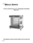
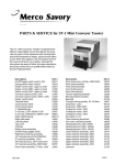
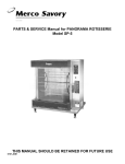
PARTS & SERVICE Manual for BG-1T Horizontal Grilling
Toaster
The BG-1T horizontal conveyer grilling
toasters are engineered for efficient,
dependable service throughout the
years. Like any piece of equipment
with moving parts, physical wear takes
its toll. When this happens, the
information in this manual will prove
helpful. Although the instructions are
easy to follow, the work should be
handled by a qualified Savory Certified
Service Technician.
THIS MANUAL SHOULD BE RETAINED FOR FUTURE USE
1200-JDM
07011
PARTS LISTING for BG-1T
DESCRIPTION PART#
DESCRIPTION PART #
Bearing retainer, front (Pk/4)
1” plastic leg (Pk/4)
90 Deg strain relief bushing Metal
Speed control
Conveyor drive sprocket 14T
Front spacers
Bearings
Terminal block
Thermostat knob
1” metal legs (Pk/4)
Power indicator light
Handle shield, black
Strain relief bushing
Strain relief lock nut
Speed control decal
Front adjustment pins
Thermostat
Hi-limit control
Motor Fan
Belleville washers
Conveyor wire belt 5”-69 links
Rear spacers
6’ cordset 120V NEMA 5-15P
On/off rocker switch 15A
Master link 5” conveyor wire belt
Coated platen sheets (Pk/10)
Heater platen 120V 1500W
Platen power cord
Platen cover
Platen back cover
Teflon strip, heat barrier
Thermostat insulator
Platen brace
Platen insulation holder
Platen sheet holder bracket
Platen safety latch
Front platen adjustment bracket
Bearing retainer, rear
Conveyor tension adjust. Bracket
Loading ramp insert
Delivery chute
Toast tray
Front shelf
Rear adjustment cover
Left side panel
Right side panel
Platen handle
Motor assy., w/fan 120V
Drive chain 60 links
Platen mounting bracket
Front shaft assy., 5”
Rear shaft assy., 5”
Loading ramp
Motor sprocket 12T
12381
12668
12682
12464
13733
14606
22754
21858
22566
41087
51052
68258
69523
69524
69526
69527
69528
69529
12946
69532
69538
69542
69549
69550
69754
69556
69571
69574
69576
69578
69580
69581
69584
69605
69607
69609
69622
69654
69655
69666
69670
69671
69693
69703
69707
69708
69714
69716
69719
69747
69751
69752
69773
69787
PARTS REPLACEMENT INSTRUCTIONS
WARNING:
2.
DISCONNECT UNIT FROM POWER SOURCE
BEFORE ATTEMPTING AND SERVICE PROCEDURES.
3.
4.
General instructions:
The BG-1T has two 5” wide conveyor belt systems.
The parts replacement information contained in this
manual will pertain to the BG-1T model only.
5.
B Conveyor Speed Control Replacement
A Panel Removal
1.
All parts replacement procedures will require the
removal of one or both toaster side panels and/or
the bottom panel. Parts replacement procedures
on the platen assembly will require the removal of
the platen cover and the platen back panel.
To remove either the right or left side toaster panel,
remove all 5 sheet metal screws and pull downward
on the panel to remove.
To remove the bottom toaster panel, remove the 2
sheet metal screws.
To remove the platen cover, remove the 4 sheet
metal screws and lift upward.
To remove the platen back panel, remove the 6 sheet
metal screws.
2
(Figure 2)
1. Remove the right side panel. (Section A)
2. Pull off speed control knob.
3. Disconnect the 2 wire leads, one at the on/off switch
and the other at the wire connector.
4.
5.
Remove the nut securing the control to the
front toaster panel and pull control out from
back side of panel.
Reverse this procedure to install new
control. (Refer to wiring diagram)
E Terminal Block Replacement
(Figure 2)
1. Remove the right side panel. (Section A)
2. Disconnect all wires from terminal block noting proper
orientation.
3. Remove the 2 nuts and screws securing the terminal
block to the toaster floor and remove terminal block.
4. Reverse this procedure to install new terminal block.
(Refer to wiring diagram)
C Power Indicator Light
Replacement
(Figure 2)
1. Remove the right side panel. (Section A)
2. Disconnect the 2 wires from back of light.
3. Press spring loaded tabs on back of light
and push light through front of panel.
4. Insert new light from front of panel and snap
into place.
5. Re-attach wires to light terminals. (Refer to
wiring diagram)
F Main Power Cord Replacement
(Figure 2)
1. Remove the right side panel. (Section A)
2. Disconnect wire at on/off switch, terminal block and
ground wire.
3. Remove retaining nut securing the 90 deg., elbow to the
toaster floor and remove power cord along with the 90
deg., elbow.
4. Remove the power cord from the 90 deg., elbow by
loosing the two screws on the 90 deg., elbow.
5. Reverse this procedure to install a new power cord.
(Refer to wiring diagram)
D On/Off Switch Replacement
(Figure 2)
1. Remove the right side panel. (Section A)
2. Disconnect all wires from back switch noting
proper orientation.
3. Press spring loaded tabs on back of switch
and push through front of panel.
4. Install new switch from front of panel and
snap into place.
5. Re-attach wires to switch terminals. (Refer
to wiring diagram)
G Drive Chain Replacement
(Figure 2)
1. Remove the right side panel. (Section A)
2. Loosen, but do NOT remove, the 4 motor mounting
screws.
3. Slide motor slightly to loosen drive chain tension and
remove drive chain from around the motor and conveyor
sprockets.
3
4. Install new drive chain over sprockets with
open looped side of chain facing upward.
5. Slide motor to remove excess slack from
drive chain and tighten the 4 motor mounting
screws.
2.
H Conveyor Chain Sprocket
Replacement
5.
3.
4.
6.
(Figure 2)
1. Remove the right side panel. (Section A)
2. Remove the drive chain. (Section G)
3. Loosen the set screw on hub of sprocket and
slide sprocket off shaft.
4. When installing new sprocket, make sure set
screw rests in hole on the shaft.
5. Replace the ddrive chain. (Section G)
7.
8.
I Motor Sprocket Replacement
9.
(Figure 2)
1. Remove the right side panel. (Section A)
2. Remove the drive chain. (Section G)
3. Loosen the 2 set screws on hub of sprocket
and slide sprocket off shaft.
4. When installing new motor sprocket, make
sure that one of the two set screws rests on
the flat of the motor shaft.
5. Replace drive chain. (Section G)
Loosen, but do NOT remove, the bearing
retainer brackets on both sides of toaster.
Loosen, but do NOT remove, the tension
adjusting brackets on both sides of toaster.
Push front conveyor shaft towards the back
of toaster to loosen belt tension.
Separate the conveyor belt at any link and
slide out of toaster.
When installing new conveyor belt, check for
proper link orientation. (Figure 5)
Starting at front of toaster, slide belt under
front shaft and push towards rear of unit.
Bring belt up and over rear shaft and pull
towards front of unit. Make sure belt is
resting on top of all belt support guides. Reconnect links. CAUTION: MAKE SURE
BELT IS NOT INSTALLED AT AN ANGLE.
Pull forward on front conveyor shaft until
excess slack is removed from the belt.
Tighten tension adjusting brackets and
bearing brackets on both sides of toaster.
L Front And Rear Shafts
And Bearing Replacement
(Figure 2, 4 & 5)
1. Remove both right and left side panels.
(Section A)
2. To remove front shaft and front shaft
bearings: Remove bearing retainers on
both sides of toaster.
3. Loosen conveyor belt tension adjusting
brackets on both sides of toaster.
4. Bearings (with shaft) will now slide out. Note
proper orientation of spacers.
5. To remove rear shaft and rear shaft
bearings: Remove drive chain (Section G),
and conveyor shaft sprocket. (Section H)
6. Remove rear bearing retainer brackets
from both sides of toaster.
7. Bearings (with shaft) will not slide out. Note
proper orientation of spacers.
8. Replace bearings, spacers and shaft.
Replace conveyor belt tension adjusting
brackets (on front shaft) and bearing retainer
brackets on both front and rear shafts.
9. Replace conveyor shaft sprocket and drive
chain on rear shaft.
10. On front shaft, adjust tension of conveyor
belt to remove excess slack from belt.
J Motor Replacement
(Figure 3)
1. Remove the right side panel and the panel
from underside of unit. (Section A)
2. Remove the drive chain (Section G), and the
motor sprocket. (Section I)
3. Disconnect the wire leads at the terminal
block and at the wire connector.
4. Remove the 4 motor mounting screws and
lock washers and remove motor.
5. Install new motor and secure with the 4 motor
mounting screws and lock washers.
6. Re-attach wire leads at the wire connector
and at the terminal block. (Refer to wiring
diagram)
K Conveyor Belt Replacement
(Figure 2 & 5)
1. Remove both the right and left side panels.
(Section A)
4
5
PLATEN ASSEMBLY COMPONENTS PARTS REPLACEMENT
INSTRUCTIONS:
R Thermostat Replacement
(Figure 6 & 7)
1. Remove entire platen assembly from toaster
body. (Section Q)
2. Remove the 6 sheet metal screws on back
panel of platen assembly and remove the
panel.
3. Disconnect wires going to the hi-limit control
and the power cord.
4. Remove the temperature control knob.
5. Remove the 2 screws (located behind the
temperature control knob) securing the
thermostat to the retaining bracket.
6. Remove the insulation from the platen
insulation holder.
7. Remove the thermostat bulb retainer bracket
which slips over the capillary tube, and
carefully pull thermostat and bulb from inside
the platen.
8. IMPORTANT: Before installing new thermostat, coat entire capillary bulb with a thin layer
of Thermal Mastic compound.
9. Set thermostat to desired platen temperature.
(Section U)
General Instructions: The following instructions
will describe how to replace components of the platen
assembly. To gain access to the internal parts of the
platen you must first remove the platen cover by
removing the 4 sheet metal screws securing the cover
to the platen assembly. For some parts replacement
procedures you will be required to remove the entire
platen assembly from the toaster body. Instructions on
platen assembly removal will be found in Section P.
M Platen Handle Replacement
(Figure 1 & 6)
1. The platen handle screws onto the threaded weld
stud. Be sure black handle shield is properly
located between the handle and the platen side.
N Hi-limit Control Replacement
(Figure 6)
1. Disconnect the 2 wires at the control.
2. Remove the 2 screws and washers securing the
control to platen.
3. Reverse this procedure to install new control.
(Refer to wiring diagram)
4. Before installing new hi-limit control, coat entire
bottom of control with Thermal Mastic compound.
S Platen Replacement
(Figure 6 & 7)
1. Remove platen power cord. (Section P)
2. Remove entire platen assembly from toaster
body. (Section Q)
3. Remove thermostat. (Section R)
4. Remove the 2 sheet metal screws securing
platen strip to platen insulation holder.
5. Disconnect all wires from platen and hi-limit
control.
6. Remove the 4 large nuts and Belleville
washers securing the platen. IMPORTANT:
Note proper orientation of Belleville washers.
7. Remove the 4 screws and nuts securing the
platen brace and remove the brace. Note
proper orientation of brackets and platen
brace.
8. Remove platen.
9. IMPORTANT: When replacing platen, be
sure that teflon strip is properly located
between the rear edge of the platen and the
platen insulation holder.
10. Before installing new platen, coat entire
bottom surface with Thermal Mastic compound.
11. Reverse this procedure to install new platen.
P Platen Power Cord Replacement
(Figure 6 & 7)
1. Disconnect the wire leads at the thermostat,
platen and the ground wire.
2. Remove the lock nut from inner wall and
carefully pull out power cord with wires intact.
3. Reverse this procedure to install new power
cord. (Refer to wiring diagram)
Q Platen Assembly Removal
(Figure 6 & 7)
1. To replace the following components, the
entire platen assembly must first be removed
from the toaster body.
2. Remove platen cover and platen cord. (Section P)
3. Remove the acorn nut from the platen pivot
rod and slide out rod. Note proper orientation
of washers on both platen assembly.
4. Carefully lift off platen assembly.
6
Adjust the two front adjustment pins until they just
touch the bottom surface of the front adjustment
brackets. Tighten lock nut on each.
8. Tighten the four #10 nuts on the rear adjustment
brackets. Adjust the two rear adjustment nuts until
they just touch the lower edge and tighten the lock
nut on each.
9. Remove platen height adjustment device. Retain
for future use.
10. Replace side panels and rear adjustment cover.
7.
T Platen Height Adjustment
Instructions
(Figure 3 & 10)
It is recommended that the amount of space between
the conveyor belt surface and the platen surface be ¼”
less than the thickness of the product being toasted.
1. Remove both side panels and the rear adjustment
cover.
2. Loosen the lock nut on the two front adjustment
pins. (Figure 3)
3. Loosen, but do NOT remove, the 4 #10 nuts on the
rear adjustment brackets (2 on each bracket), and
the lock nut on each bracket.
4. CAREFULLY lift the loosened platen and rest on the
safety latch. (Figure 3). Position height adjustment
device over conveyor belt making sure the slots fall
over the two front adjustment pins.
5. Slide adjustment device to the desired “step” height.
6. CAREFULLY lower loosened platen making sure
platen making sure platen comes into contact with
the same “step” in all four corners,
IMPORTANT
BEFORE TIGHTENING ADJUSTMENT HARDWARE,
BE SURE PLATEN IS RESTING SQUARELY ON THE
SAME “STEP” IN ALL FOUR CORNERS. PLATEN
SHOULD NOT WOBBLE.
U Platen Temperature Adjustment Instructions
7
(Figure 6)
1. Remove platen cover. (Section A)
2. To increase platen temperature; turn temperature
control knob clockwise. To decrease platen
temperature; turn temperature control knob counterclockwise.
3. IMPORTANT: Allow at least a 30 minute warm-up
or cool-down period. It is recommended that
temperature should be noted at the center point of
the platen surface. There will be a 10 deg., to 20
deg., drop in temperature between the actual
platen casting and the platen cooking surface.
Platen will reach set temperature after 4 to 5
complete temperature control cycles.
4. Replace platen cover.
8
9
10
WIRING DIAGRAM
BG-1T
11
208V SYSTEM PARTS LIST
CORDSET
DRIVE CHAIN
PLATEN HEATER
MOTOR ASSY.
SPEED CONTROL
CONVEYOR SPROCKET 14T
#69940
#69538
#69870
#69935
#69880
#13300
12
1111 N. Hadley Rd.
Fort Wayne, In 46804
Tel. 800-701-2992
Fax (260) 436-0735
www.mercosavory.com