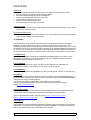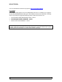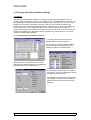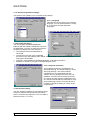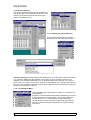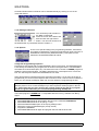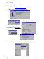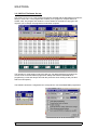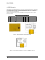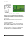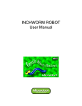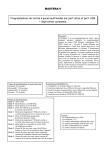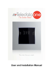
1
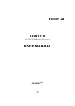
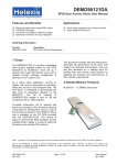
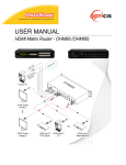
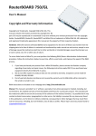
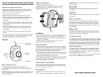
MASTERA
USER REFERENCE MANUAL
1: Introduction
Congratulations on your purchase of the MASTERA Universal Card programmer.
The MASTERA programmer combines the functionality of several discrete programmers in
one design. MASTERA is developed especially to program ISO-CARDS and many variants of
the “GOLD” card and GOLD card replica family containing PIC or ATMEL processors. The
different programmer mode’s are selected trough a push-button. The selected program is
clearly indicated by a bright seven-segment LED display. A 12V net adapter powers the
programmer. The net adapter is delivered with the programmer. MASTERA is connected to
the host PC COM port with a 9 pin RS-232 cable. The programmer is measures 7 x 12 x 3cm
and is mounted in an appealing black PVC housing.
The programmer uses professional quality SMD components. The hart of the circuit is an
EPLD. The Programmable Logic Device enables upgrading of the programmer in the case
that a new programmer mode would emerge.
1: Programmer Modes
MASTERA presently contains 7 different programmer modes (Display 0 to 6).
MODE 0:
Mode 0 is the well-known PHOENIX or SMARTMOUSE programmer mode with a 6MHz clock
frequency. This mode is generally used to program ISO-CARDS trough CRD’s or to program
the EEPROM section of GOLD cards.
MODE 1:
Mode 1 is identical to Mode 0 but operates at 3.58Mhz.
MODE 2:
Mode 2 is compatible with the JDM or LUDI programmer. This mode is used to program the
PIC section of, e.g. a GOLD card. The PIC’s are usual 16F84 devices but in principal all serial
programmable PIC devices can be programmed in this mode. The programmer has an
internal voltage boost circuit that generates the required accurate 13V programming voltage.
MODE 3:
Mode 3 is used to program EEPROM’s on cards with separate I2C contacts (8 pin contacts).
You can program the EEPROM on these cards completely separate from the PIC processor.
MODE 4:
This mode is compatible with the ATMEL-JUPITER. It programs AT90s2343 on a JUPITER
card but it is also capable of programming other AVR type microprocessors on this type of
cards.
MODE 5:
Mode 5 is used to program the EEPROM direct on the JUPITER card over the separate I2C
contacts.
MODE 6:
Mode 6 is used to read and write GSM cards, German and Dutch telephone cards and
German Cash and Insurance cards.
MASTERA User Manual Rev 1.1 :
13/06/01
1/12
MASTERA
GSM cards
• You can manage the telephone book and move telephone books to other cards.
• You can create, print and edit Short Messages (SMS).
• Select and disable networks from the roaming list.
• Activate cost blocking and set the cost per unit.
• Create backup copies from your card.
• Modify, unlock and deactivate PIN’s
• View and modify the contents of card files.
Telephone cards:
• You can read the card contents and display the data and value this mode works on Dutch
and German telephone cards.
Cash and Insurance card:
• You can read and print out card information, the current balance and the last transactions
of the German Cash and Insurance cards.
2: Software
The programmer can be used in combination with several different software packages,
depending on the programmer mode. The software can be found on the Internet. The
following paragraph give’s a short description of the software and the URL where you can find
the software. It is wise to check these URL’s regularly to get software updates for bug fixing or
for new devices. All programs are working under WIN95-98. Windows 2000 and Win NT are
not supported on all programs, check the system requirements and updates on the Internet.
2.1: WinPhoenix
This program is capable of writing the embedded EEPROM trough the Processor on the
smartcard. The processor (PIC) is first programmed with “LOADER” software. Next the
EEPROM is programmed in mode #0 or #1.
2.2: CardWizard
This program is designed to upload .crd files to smartcards using a WinPhoenix or
SmartMouse interface. This software can be used in mode #0 and #1
2.3: CardMaster
This is a similar program as CardWizard. It is also used to upload .crd files in mode #0 or #1
2.4: ICProg
This program is mainly used in mode #2 and #3 to program PIC’s and EEPROMS directly on
the board. But the program can also be used in mode #1 to program embedded EEPROMS
trough the PIC using a Loader program.
The use of this program is described in more detail in the next chapter.
You can find this beautiful written program from Bonny Gijzen at his home page:
http://WWW.h2deetoo.demon.nl
2.5: PonyProg 2000
This program is used in mode #4 and #5 for the ATMEL devices and the EEPROM on the
Jupiter cards. Also this program is explained in more detail in the next chapter.
You can download last version of PonyProg at http://www.lancos.com/prog.html
(http://www.lancos.com/ppwin95.html )
2.6: ChipCard
This program is used for MASTERA mode #6. It enables read/ write operation of phone and
GSM cards. The program can be installed in different languages. It is largely self-explaining
and has an extensive help menu embedded in the program.
MASTERA User Manual Rev 1.1 :
13/06/01
2/12
MASTERA
You can download last version this program at http://www.teledata-update.de
2.7: ChipCat
This program makes optimum use of the MASTERA mode 0 to 5. It enables you to program
the internal EEPROM different card types. This software uses it’s own loader files. Following
cards can presently be programmed directly with the CHIP-CAT Revision 2.0:
•
•
•
•
The PIC/Wafer-CARD (GOLDCARD) 16F84 + 24C16.
The AVR/Yupiter-CARD, AT90S2323 + 24C16
The AVR/Yupiter-CARD, AT90S2343 + 24C16
And the FUN-Card AT90S8515 + 24C64
Note: MASTERA is a universal programmer and can therefore be used with different software
programs. When the programmer is used with Shareware or Licensed software then royalties
should be paid to the developer or reseller of that software package.
MASTERA User Manual Rev 1.1 :
13/06/01
3/12
MASTERA
3: ICProg and PonyProg Software settings
3.1: ICProg
The user could use different software to control this programmer as already mentioned.
However the IC-Prog software of Mr. Bonny Gijzen is very complete and free on the Net. The
next paragraphs containing screens from this programmer. The program is very much selfexplaining and contains a good HELP function. This part of the manual is therefore not
intended as a user manual for the software but the could help you on the way in making the
correct settings to use it in combination with the Universal Programmer. Mr. Gijzen is
continuously improving his software and adding new devices, so check from time to time his
website for upgrades. The description below is created from IC-Prog Revision 1.04 newer
revisions could be slightly different.
3.1.1: Port Settings and Hardware selection:
⇐ A similar, general overview screen is
displayed when IC-Prog is started.
The first time you have to select the serial
port and the type of programmer: These
settings are entered as shown below: ⇓
Select the proper serial port (Com1 to Com4)
And select the JDM Programmer. For WIN9x you
should select Direct I/O. Windows API
could be selected for Windows NT. The
Communication checks boxes are usually
not required. These are intended for special
hardware and test purposes.
The settings are automatically stored when
the software is closed so you don’t have to
repeat this setup every time you start the
program!
MASTERA User Manual Rev 1.1 :
13/06/01
4/12
MASTERA
3.1.2: General Programmer settings:
The Option menu enables you to customize many settings.
3.1.2.1 Language
This submenu let you select your preferred
language. You can select between a variety
of 11 European and east European
languages.
3.1.2.2 Smartcard Option
You can program embedded EEPROMs
indirectly with this software, MODE #0 or #1 from
the MASTERA. You have to make the necessary
programmer settings first in this submenu.
• The COM port where the MASTERA is
connected.
• The Device is the type of the embedded
processor in the card. (Most modern GOLD cards are 16F84. 16C84 will be found on
older type of GOLDcards
• Frequency: Select 6MHz for MASTERA Mode #0 / 3.58 MHz for Mode #1
• Multimac or Secanix is the type of LOADER program used.
3.1.2.3 Program verification
The programmed device is verified during or
after programming. The default setting is “Verify
after programming”. This means that the
complete device is programmed and then
verified. This is a good practice but it has one
drawback: most PIC devices having a security
bit. This bit prevents program readout when set.
So, when this bit set that it is impossible to verify
the programming process. For these devices it
is better to change the setting to “Verify during
programming”
3.1.2.4 Shortcut setting.
You can call device settings very fast without going
trough the separate setup menus by pre-setting
them to a shortcut key sequence. You can create 4
Shortcuts (CTRL + F1 to F4).
MASTERA User Manual Rev 1.1 :
13/06/01
5/12
MASTERA
3.1.3: Device selection:
The device can be selected out of an extensive list.
The devices that can be programmed directly in the
sockets can be found in the “Microchip PIC” list ⇒
and the “I2C EEprom” list. ⇓
3.1.4: Loading and saving data files:
Program files can be loaded or saved in
any directory and in many data formats ⇓.
A word of warning about the data formats: Reading in, e.g. a HEX file in .H16 format when it
is a .H8 will be detected by the software and results in an error message. However, the
software is not capable of detecting errors in .BIN files because this file type is not using a
CRC check or any other control check. Also the format of Binary files can differ depending on
the source that created the .BIN file. Always check a BIN file on its contents before using this
file type for programming a device.
3.1.5: The Command Menu:
The command menu is the final menu where you can select the
required action.
The device is verified automatically after programming. You have
to remember that it is not possible to verify a device when the
security bit is set. You could program a device without the
security bit and verify the program integrity after programming.
Next you set the security bit and perform the “Program Config”
(F4) action.
MASTERA User Manual Rev 1.1 :
13/06/01
6/12
MASTERA
Command ICON’s Most commands can be activated directly by clicking on one of the
command ICON’s.
3.1.5: Editing a Data field:
You can directly edit a location in
the Data or Code field.
Place the cursor at the start of the
data and click the right mouse
button. You can now choose to fill
the whole buffer or just edit the selected location ⇒
3.1.6: Special:
There is one special setting in the programming software. “Smartcard”,
This setting is intended for Trough PIC programming using a Phoenix or
SmartMouse card interface (Mode #0 and #1). This option is to be
switched of in MASTERA Mode #2 and #3.
Trough PIC Programming sequence.
Programming ISO Cards with a buried EEPROM is done in tree steps. The EEPROM device
is not directly accessible by the programmer as shown in the figure above. The EEPROM is
accessible in Phoenix Mode (#0 or #1). The buried PIC has to contain a LOADER program to
enable the serial communication. The data is transferred by a serial protocol to or from the
PIC. The PIC relays the data to the EEPROM and vice versa.
Some Smartcard PIC software having this serial protocol build in. So as soon as the PIC is
programmed you can access the EEprom date in Phoenix mode. This kind of PIC software is
ideal; you can change the EEprom data over and over without re-programming the PIC.
Most PIC software however is not prepared for “trough Pic programming” or the are using a
different protocol. So to access the EEprom you have to place a loader program in the PIC
first. This means that you have to know the original code from the PIC to re-program
the PIC’s original code when you are finished programming the EEprom!
The loader program “LOADER.hex” is compatible with the IC-Prog software from Bonny
Gijzen.
PROCEDURE:
1. Select MASTERA Mode #2 and program the PIC on the card with LOADER.hex
2. Select MASTERA Mode #0 or #1 (see § 3.1.2.2)
3. Select the SMARTCARD option in the ICprog settings menu
4. Select the correct I2C EEPROM type (usualy 24C16)
5. Program the EEPROM
6. Select MASTERA Mode #2 again and program the PIC with the final code.
MASTERA User Manual Rev 1.1 :
13/06/01
7/12
MASTERA
3.2: PonyProg Software Setup:
The software description in this chapter refers to the “PONYProg” program from Claudio
Lanconelli. (Download at http://www.lancos.com/ppwin95.html )
•
Install and start PonyProg2000 under Windows 95/98 or NT.
• The first time you have to make the correct
Hardware settings,:
Open SETTINGS, Open HARDWARE, now
select Si Prog API programmer and the
correct COM port for your PC connection.
•
Run Calibration
•
The programmer and the software is now ready to program. Select the AVR
microprocessor type or I2C Bus eeprom
MASTERA User Manual Rev 1.1 :
13/06/01
8/12
MASTERA
3.3: CHIP-CAT Software Set-up:
The CHIP-CAT rev 2.0 is a new program that works splendid with the MASTERA programmer
family in mode 0 to 5. This program also enables you to program a complete GOLD or
ATMEL card. The program also writes the correct loader for the different chip types and
requests you to change the programmer mode when required.
The operation is strait forward, select the card type (as displayed above) and select the
correct mode on the MASTERA programmer always start with the EEPROM when
programming a card and always start with the processor when reading a card (see also
GOLD140 description).
The Software should be configured first to recognize the connected MASTERA programmer.
MASTERA User Manual Rev 1.1 :
13/06/01
9/12
MASTERA
You can now READ, WRITE, ERASE and
Verify the card by clicking the different
ICON’s .
You can Load and Save data to and from the PC
with the 4 file icon’s. The two on the left (identified
by “1”) are used for the processor part. The two on
the right (identified by “2”) are used for the
EEPROM part of the card.
Also with this programmer you can manipulate the different typical processor setting as, e.g.
the Oscillator setting or Code Protect bit.
MASTERA User Manual Rev 1.1 :
13/06/01
10/12
MASTERA
4: CARD Information
ISO Cards are sold under different names and colors, the are called SmartCards, Gold Wafer
Cards, Platinum, Galaxy or Gold card, MM2 Gold Wafer Cards and so on. Also variants build
on a small thin PCB containing a discrete PIC and EEPROM can be found. The internal
layout of most cards is standardized.
The ISO card interface on the programmer enables you to program the 16C84 or 16F84
inside these cards.
SMARTCARD CONTACT DESCRIPTION
Pin
C1
C2
C3
C4
Name
Vcc
MCLR
RB6/Osc1
N/C (or SDA)
Function
Power Supply
Master Clear
Clock Input
No Connect (or SDA)
Pin
C5
C6
C7
C8
Name
Vss
N/C
RB7
N/C
Function
Ground
No Connect
Data I/O
No Connect (or SCL)
Figure 1: GOLD Card layout (Mode #0 , #1 and #2)
SDA
SCL
Figure 2: GOLD card replica with separate contacts for EEPROM (Mode #3)
MASTERA User Manual Rev 1.1 :
13/06/01
11/12
MASTERA
Figure 3: ATMEL – Jupiter card (Mode #4 & #5)
The figures above are the schematic drawing of some of the popular SmartCards on the
market. The PIC devices in fig1 and 2 are identical wired. The 24LC16 in fig 1 is connected
internally to the PIC processor and can only be accessed trough the PIC. Fig 2 type has an
internal EEprom but the program lines (SDA & SCL) are also directly accessible trough pin C4
and C8.
Card type Fig 2 and Fig 3 can be programmed direct. The user can program the Processor an
EEprom independently.
Note: Do not select the SmartCard programming option in ICProg for this card type (see
above!)
The 1e type requires a special action called Trough PIC programming. See § 3.1.6
5: Programming Discrete Devices
Discrete PIC or ATMEL processors and I2C Eeprom’s can also be programmed by placing
them on an adapter card. This adapter card is usually a GOLD card replica as e.g. the “Two
Stone Card”. This type of card has the same circuit as Fig 1 or Fig 2. The chips are placed in
IC sockets. The JUPITER type card can be used for ATMEL devices or I2C Eeprom’s (fig 3).
Empty adapter cards are sold separately.
GSM SIM cards are normally sold in the standard card size with a break-out area. You can
use this standard card to change the MINI SIM’s back to the original card size (use a small
piece of tape on the back). You can also find an adapter in your local telecom shop.
MASTERA User Manual Rev 1.1 :
13/06/01
12/12