1
US006222484B1
(12) United States Patent
(10) Patent N0.:
Seiple et al.
US 6,222,484 B1
(45) Date of Patent:
(54) PERSONAL EMERGENCY LOCATION
Apr. 24, 2001
“Get A Grip”, editor, Boating World, Jun. 1999.
SYSTEM
* cited by examiner
(76) Inventors: Ronald L. Seiple, 1063 Koohoo Pl.,
Kailua, Oahu, HI (US) 96734; Robert
(*)
Notice:
B- _SeiPle, 12319 Cane Albara #3, E1
calon, CA (Us) 92017
Primary Examiner—Daniel T. Pihulic
(74) Attorney, Agent, or Firm—Leighton K. Chong
Subject to any disclaimer, the term of this
patent is extended or adjusted under 35
(57)
U_S_C_ 154(k)) by 0 days_
A personal emergency location system (PELS) employs a
(21) APPL N0, 09634,859
Jun. 16, 1999
ABSTRACT
small battery-powered personal unit Worn by a person Who
may be lost overboard. The personal unit has a GPS receiver
and processor for determining the person’s GPS location
coordinates, and an RF transmitter for sending an RF
emergency signal With the GPS coordinate data to a nearby
vessel Within a short range. The nearby vessel is equipped as
(22)
(51)
Filed:
Int- Cl?
(52)
(58)
US. Cl. ....................................................... .. 342/357.09
Field Of Search .................. .. 342/35709; 340/5736,
a base Station to receive the RF emergency Signal and the
person’s GPS Coordinate data and Send out an RF broadcast
340/984; 701/213; 116/210
signal of the person’s position over a long range to the
H04B 7/18 5
authorities or other rescue vessels. The personal unit is
(56)
References Cited
updated With the most current GPS data and recharged
U_S_ PATENT DOCUMENTS
during inactive periods vvhen the person on-bo'ard a vessel
equipped as a base station. The personal umt sends the
4,219,819 *
8/1980 Patel ................................... .. 116/210
emergency Signal until an acknowledgment Signal is
5,119,101
5,191,792
6/1992 Barnard .
3/1993 Gloor .
received from a base station, Whereupon the personal unit is
placed in a “Receive-Only” mode to save battery poWer. The
5,408,238 *
4/1995
5,420,592
5/1995 Johnson .
Smith ............................ .. 342/357.09
5 552 794
9/1996 Colley et a1__
base station is equipped With a GPS system that can be
updated With the most current GPS data, so that it can
5,815,126
5,862,511
9/1998 Fan et a1__
1/1999 Croyle .
calculate an accurate vector of approach to the person’s
position. The PELS system handles communications in the
preferred GMDSS/DSC signal format (as de?ned by the
OTHER PUBLICATIONS
International Maritime Organization).
“Keeping Tabs On Criminals”, J. Hosen et al., IEEE Spec
trum, Feb. 1995.
20 Claims, 7 Drawing Sheets
BROADCAST" (W
SIGNAL
A,
18
U.S. Patent
Apr. 24, 2001
Sheet 1 0f 7
US 6,222,484 B1
BROADCAST” (W
SIGNAL
A_
1s
FIG. 1
V
1 CH
~86; I31
g
2 (D ‘D
-
/~
‘ma
18 <
.
_ I
P'EEs UNIT’
GPS
SYSTEM
I
I
_
PEEs UNIT "
51
I
-
I
K
I
I
U
PIE" UN”: FEES UNIT“
' TRANSCEIVER
\
31a
Q
L__
5°
FIG. 2B
PELS UNIT
‘
U.S. Patent
Apr. 24, 2001
Sheet 2 0f 7
US 6,222,484 B1
GPS L1 VHF
Antenna Antenna
22a
26
GPS
Digital Signal
Processor
Crystal 27
Oscillator
Serial
23 Data
H Radio 2
1
Microprocessor Comm
Address-bus
Lines
<—>
Selim
Data
Control
Lines
Power Supply
Circuit
(supplies all
32
components)
\—____———__—_————_ _——___-n__——‘
+
-
31
Battery Pack
29
10
gain Equipment Housing
28
30
Serial Indicator Activation
"0
Lights switch
Figure 2A
J
U.S. Patent
Apr. 24, 2001
Sheet 3 of 7
US 6,222,484 B1
Dormant State Flowchart Figure 3.1
101
Set Maximum
Power Conservation:
a) GPS subsytern power off.
b) Radio subsystem power off.
c)lndicator Lamp Green blink slowly.
d) CPU clock speed to minimum.
;
Else
__-__>
If switched on go to:
Else
.htlvated
103
.
.
'
.
h - tand'
If unit 120115. t s
Download/Update
104
Is battery charge
> 80%?
105
Set Indicator Lamp
Red to blink slowly.
106
Are GPS data
?les valid?
ephemeris < 4hrs
107
If ephemeris >3 hrs
attempt every 5 minutes:
Dormant/Update
108
1 09
Do system
Set Indicator Lamp
diagnostics tests
Red to be on
pass?
continuously.
U.S. Patent
Apr. 24, 2001
Sheet 4 0f 7
US 6,222,484 B1
Dormant/U?ate Flowchart Figure 3.2
201
Set System for GPS Update:
a) GPS subsytem power on.
b) Radio subsystem power off.
c)lndicator Lamp Green blink quickly.
(1) CPU clock speed as appropriate for GPS
processing.
203
Set GPS subsystem
power off.
204
Download and save latest Almanac,
and Ephemeris data sets from
available GPS satellites.
Calculate and record current
Position and Time datum.
l
U.S. Patent
Apr. 24, 2001
Sheet 5 of 7
US 6,222,484 B1
Download/Update State Flowchart Figure 3.3
301
Set System for GPS Download:
a) GPS subsytem power off.
b) Radio subsystem power off.
c)Indicator Lamp Green blink quickly.
d) CPU clock set to full-speed.
303
Were hardware
Yes
faults present?
No
l
304
Wait until battery pack is fully charged.
Y
305
Download and save latest
Almanac, and Ephemeris data
sets and current Position and
Time datum from host syste
l
306
Upload fault
status to host.
U.S. Patent
Apr. 24, 2001
Sheet 6 0f 7
US 6,222,484 B1
AWE
401
Set System for Distress Transmittal:
a) GPS subsytem power on.
b) Radio subsystem power on.
c)Indicator Lamp Red blink quickly.
d) CPU clock set to full-speed.
f___.l
402
Start processing new GPS
position ?x. Turn GPS
power off when complete.
403
Is last ?x older
than 10 min‘?
Transmit Distress signal
with position and time from
last download, update to
new GPS position ?x and
time when GPS Receiver
has processed new ?x.
405
Wait for prescribed interval.
(Interval period increases at
a prescribed rate to
Has Distress been
preserve battery power,
while still in Activated
Acknowledged?
mode.)
407
Go to:
Receive Mode RPD
U.S. Patent
Apr. 24, 2001
US 6,222,484 B1
Sheet 7 of 7
Receive Mode 152D) State Flowchart Figure 3.5
501
Set System for Radio Receive mode:
a) GPS subsytem power off.
b) Radio receiver subsystem power on.
c)Indicator Lamps Red & Green blink slowly.
d) CPU clock set to slow-speed.
Yes
Has radio received
n update request?
Has operator manually
Yes
re-activated the
system?
504
Go to:
MAME.
US 6,222,484 B1
1
2
PERSONAL EMERGENCY LOCATION
SYSTEM
mate position and carrier Doppler frequency (i.e., the fre
quency shift carried by the rate of change in range to a
FIELD OF INVENTION
moving satellite) of each satellite in the constellation.
Ephemeris data consist of detailed orbital information for
The present invention relates to a system and method for
locating a person lost overboard from a vessel. More
particularly, the invention concerns a system that is attached
to the person at all times While at sea and operates to signal
the speci?c observed satellite. It can take up to 15 minutes
to initialiZe a GPS system if the almanac and ephemeris data
the person’s exact location to the vessel or to other rescue
be equipped With a small GPS receiver and a radio to send
their latitude and longitude coordinates over the radio. This
are not available or not up to date.
GPS-based locator systems have required individuals to
vessels.
requires the person to have both devices When lost, Which is
unusual for most recreational boating situations and typi
cally only occurs With military pilots Who are thus equipped.
BACKGROUND OF THE INVENTION
For years persons have been lost overboard and not been
able to be located even When near their oWn ship. Although
Emergency Position Indicator Radio Beacons (EPIRBs)
have been Widely used for decades, they have not been
sufficiently small enough to be carried by individuals.
Additionally, EPIRBs use radio frequency direction ?nding
Another approach has been to carry a device that sends an
15
broadcast an alert of the overboard situation and give at least
the vessel’s location With its on-board GPS navigation
system When the emergency signal is received. This Would
provide rescue vessels With the position of the vessel from
Which the person has fallen overboard, but cannot provide
and therefore are not very accurate in pin-pointing an
individual or even a small boat lost at sea. They are not even
very effective for alloWing the person’s ship to locate the
the exact location of the person nor an update of the person’s
person Who has fallen overboard. EPIRBs are typically used
location adrift With the current. Aperson overboard in heavy
by the United States Coast Guard (USCG) service, Which
continually monitors for EPIRB emergency radio broadcasts
and have the ability to determine the location of the EPIRB
RF emergency signal to the person’s vessel or a nearby
vessel When overboard, so that the creW on the vessel can
sea often cannot be seen even one hundred feet aWay from
25
a pending rescue vessel. If rescue is not accomplished
by Doppler signal processing from the satellite receivers. An
quickly, that person can easily be lost. Larger ships and
EPIRB-determined location is only accurate to Within sev
eral square miles and can be off as much as thirty square
miles.
their course, so not having an exact location of the overboard
person can greatly diminish the effectiveness of the rescue
Other rescue locating devices include mirrors, strobes and
lights, Whistles ?ares and other items. These are certainly
better than nothing but they are not ideal. In many instances,
these devices must be operated by the overboard person Who
may quickly be overcome and incapacitated by the environ
sailing vessels typically take time to turn around and retrace
effort. In small sailing vessels often only one person is on
Watch; if that person falls overboard, it may be hours before
it becomes knoWn.
SUMMARY OF THE INVENTION
35
In accordance With the present invention, a personal
emergency location system (PELS) comprises a small
battery-poWered personal unit adapted to be Worn by a
ment.
More recently, Global Positioning Systems (GPSs) have
been used to locate lost persons. GPS systems determine
person Who may have fallen overboard from a vessel having
a GPS receiver and processor for determining the person’s
GPS location coordinates, and an RF transmitter for sending
an RF emergency signal of the person’s coordinate data to
a nearby vessel (such as the person’s vessel) Within a short
position by receiving signals from a sub-set of the 24 US.
GPS satellites that are in operation. The signals transmitted
by each satellite include a time code, Which is synchroniZed
With the time codes transmitted by the other satellites. The
GPS system calculates an earth-centered-earth-?xed (ECEF)
position for the location Where the signals are received,
based on the time differences betWeen the signals received
from the satellites and the knoWn location of the satellites.
ECEF positioning uses a 3-axis coordinate system With the
origin located at the center of the earth, and can be translated
to a global coordinate-based system (i.e., latitude and
45
longitude).
The GPS satellites are not in geo-synchronous orbits. The
location of the satellites are determined from almanac and
Within a short range can receive the PELS emergency signal,
provide a distress acknowledgment, mark the position of the
ephemeris data either doWnloaded from the ship’s host
person based on the received emergency signal, and broad
system or from the satellites themselves. Almanac data are
good for several Weeks and are updated Weekly. Ephemeris
range. The PELS personal unit is updated With the most
current ephemeris data during a time When the person is
inactive on-board the vessel by plugging it into an input
module connected With the vessel’s GPS system. The person
Wears the PELS personal unit When on active duty on the
vessel. If the person falls overboard, the PELS personal unit
is activated to send an emergency signal With the person’s
location coordinates. The person’s vessel or a nearby vessel
55 cast an alert and emergency signal to other rescue vessels or
stations of the person’s position.
data are good for about 4 hours and are updated hourly.
Almanac data consist of general information regarding all
In a preferred embodiment of the present invention, the
satellites in the constellation and atmospheric data for a
PELS personal unit includes a ROM memory for storing a
GPS calculation program of machine-readable instructions
in order to determine the person’s GPS location coordinates
to be sent via radio frequency to a nearby GPS-equipped
vessel. The RF signal is preferably formatted as a digitiZed
determination of RF propagation delays. Almanacs have
approximate orbital data parameters for all satellites. The
typical ten-parameter almanac describes the satellite orbits
over extended periods of time of up to several months and
a set for all satellites is sent by each satellite over a period
of 12.5 minutes minimally. Signal acquisition time on
receiver start-up can be signi?cantly aided by the availabil
ity of current almanac and ephemeris data. The approximate
orbital data are used to preset the receiver With the approxi
data packet transmitted at 156.525 MHZ, meeting all Inter
national Maritime OrganiZation (IMO) speci?cations for
65
digital emergency radio communications.
The PELS system also requires a GPS-based system
on-board the person’s vessel or a nearby vessel (referred to
US 6,222,484 B1
3
4
as the “base station”) that is able to receive the distress
signal over a longer range and at higher poWer to other
rescue vessels, emergency communications stations, such as
signal from the PELS personal unit and provide a distress
acknowledgment to it. The base station translates the
received personal unit’s GPS position into its oWn naviga
tion program and calculates an intercept vector (range and
bearing) to the individual or plots the location of the
a USCG station, or even to a satellite receiver for relay.
In a preferred embodiment of the invention, the base
station (vessel) is equipped With a GPS system and a Global
Maritime Distress and Safety System (GMDSS) radio,
Which is de?ned by the International Maritime OrganiZation
(IMO) and the United States Coast Guard (USCG) as the
individual on an electronic chart. The base station can have
an emergency communications system Which Will receive
the distress signal and alert the operator With the overboard
person’s positional information. The base station can per
form a “Distress Relay” to other appropriate authorities (as
10
neXt generation of maritime radio communications. GMDSS
de?nes the use of maritime radio systems and speci?cally
15
receiving digitiZed data concerning general broadcasts and
de?ned by the IMO). Upon receipt of the “Distress
Acknowledgment”, the personal unit Will enter a standby
mode to preserve battery poWer and enable an
acknoWledgment-received indication for the distressed indi
distress signals. DSC-equipped radios are classi?ed as to
vidual. This can be done by use of an indicator light(s),
audible signal or vibration. The lost person thus knoWs by
the indicator that his distress signal has been received.
The present invention also encompasses the related
method for determining the eXact location of lost persons
de?nes the digitiZed distress signaling capability of stan
dardiZed maritime systems, called Digital Selective Calling
(DSC). DSC is implemented on each radio frequency band
(MF, HF, and VHF) as a single channel for transmitting and
their frequency band of operation and their inherent capa
bility. The classi?cations are listed as Class A—G.
20
The preferred PELS system uses GMDSS channel 70 for
marine applications. Channel 70/DSC is the neW interna
tional emergency frequency and Will be required by all
Safety Of Life At Sea (SOLAS) ships by the year 2000.
equipped With a PELS personal unit, Whether on ocean or
land.
Channel 70 operates in the VHF band at 156.525 MHZ and
Will be monitored by all vessels carrying GMDSS/DCS.
BRIEF DESCRIPTION OF THE DRAWINGS
25
The features, objects and advantages of the invention Will
This includes all international rescue agencies and all
(SOLAS) regulated vessels engaged on international
be described in detail beloW in conjunction With the accom
voyages, except: cargo ships less than 300 gross tonnage;
panying draWings, in Which like reference numerals desig
nate like parts throughout, Wherein:
ships of War and troopships; ships not propelled by mechani
cal means; Wooden ships of primitive build; pleasure yachts
not engaged in trade; ?shing vessels; and ships being
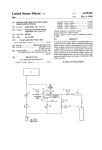
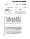
FIG. 1 is a diagram of use of the personal emergency
30
navigated Within the Great Lakes of North America.
HoWever, it is generally assumed that most commercial and
location system (PELS) including the personally-Worn
device and the base station in accordance With the invention.
FIG. 2A is a diagram shoWing the components of an
embodiment of the personal PELS unit, and FIG. 2B is a
diagram illustrating the components of the base station.
FIGS. 3.1, 3.2, 3.3, 3.4, and 3.5 are ?oWcharts illustrating
the sequence of steps performed by the main program and
recreational boaters that do not fall under the SOLAS
35
subroutines used to operate the PELS system.
DETAILED DESCRIPTION OF THE
INVENTION
Referring to FIG. 1, a personal emergency location sys
tem (PELS) in accordance With the present invention
employs a small, battery-poWered personal unit 10 Worn by
40
45
a person fallen overboard, and a GPS-equipped transceiver
system 18 on board the person’s vessel or any thus-equipped
nearby vessel. Once overboard the person activates the
personal unit 10 to initialiZe its GPS receiver. Preferably,
activation Will also in?ate and deploy a balloon 12 Which
50
optimiZe the trade-off betWeen operational life-span and
limited battery capacity.
holds an antenna 14 for the personal unit above the Water.
The antenna may be carried Within a plastic sleeve line and
on the inside of the balloon. The balloon may also be dyed
Once the personal unit’s signal is received by a base
station, the base station translates that signal into a GPS
location and the individual’s ID code. The ID code Will
a ?uorescent color to serve as a visual marker to rescue
personnel.
regulations Will also choose GMDSS radio equipment to
maintain compatibility and utiliZe the installed base of radio
equipment, thereby providing the PELS system With a broad
base of potential rescuers.
The basic operation of this invention is simple but
requires a unique combination of GPS reception, radio
transmission and reception, poWer management, and
antenna design. The core of the system is the small personal
unit Worn by individuals. Once activated, the small personal
unit calculates its position using a GPS receiver and sends
that position by RF to a base station. For marine
applications, the RF signal uses the GMDSS/DSC frequency
of 156.525 MHZ. This signal is sent in a digitally coded data
packet format as speci?ed by the IMO to meet all GMDSS/
DSC requirements. It sends these bursts at speci?c time
intervals With a decreasing repetition rate calculated to
55
identify the signal to a speci?c individual and ship. For
rescue operations this is extremely important as it Will
The personal unit’s GPS receiver receives the available
GPS satellite transmission signals and its processor deter
mines the person’s GPS location coordinates. The PELS
personal unit Will start emitting its initial “Distress Call”
transmission(s) after activation. The unit’s RF transmitter
sends an RF emergency signal With the GPS location data
over a short range (line of sight) from the battery-poWered
unit. Depending on the transmitter poWer level chosen, and
the placement (height) of the antenna, this short range can be
60
anyWhere from 3 to 15 or 20 miles. The person’s vessel or
65 the unit. In the later case, if a neW aircraft or surface vessel
a nearby vessel Within the short range (the “base station”)
comes nearby, the personal unit may be turned on to notify
that neW vessel. Upon receiving a DSC “Individual Station
can receive the RF emergency signal and send a broadcast
reduce false alerts to a minimum by alloWing rescue opera
tions to determine if the situation is real or not. Once the
base station receives the information, it sends a DSC
“AcknoWledgment Signal” to the personal unit. When the
personal unit has received the acknoWledgment signal, it
goes into a receive-only mode (RPD mode). The base station
or any other base station can re-activate the personal unit at
any time, or it can be commanded by the individual Wearing
US 6,222,484 B1
6
5
Radio frequency or channel
Call” With its oWn ID code as the intended recipient, the
Display
PELS personal unit Will begin retransmitting its “Distress
Call” until another “Distress Acknowledgment” signal is
Receive geographical area calls
Alarm
Optional means for canceling a distress alert
received, Whereupon it goes back into RPD mode. This
technique saves on battery poWer for the personal unit. Since
any base station can command an updated position of the
personal unit, any GMDSS/DSC equipped ship, or aircraft
In FIG. 2A, a preferred circuit implementation for the
PELS personal unit 10 is illustrated. The principal compo
could determine the position and effect a safe recovery.
nents of the PELS personal unit are a GPS receiver 20, an
The PELS personal unit can thus provide GPS signals of
the person’s eXact location to the base station using DSC
radio signals. Unlike other current systems that use RF/DF
10
integrated DSC/RF transceiver 21, antennae 22a for DCS
reception and transmission and 22b for GPS reception Which
are eXternal to the personal unit’s housing (as shoWn in the
to locate someone, this system provides the more accurate
outer solid line), microprocessor 23, ROM memory 24,
GPS-calculated position of latitude and longitude in tenth of
RAM memory 25, and a GPS processor 26. The GPS
processor 26 and unit microprocessor 23 may be formed as
separate IC units, or as a single IC. The GPS receiver 20 is
seconds. The base station then uses the lat/long information
to determine the eXact position of the distressed individual,
15
typically a specialiZed front-end multi-channel radio fre
quency receiver IC. The GPS receiver 20 outputs data used
to determine ECEF ?Xes to the GPS processor 26. The
Which can be displayed electronically on a chart or map, or
provided in vector format (bearing and distance from the
rescuing platform’s current position) to effect a recovery.
The personal unit must be able to receive GPS and DSC
frequencies at all times. This is accomplished by using a
20
a preferred microprocessor is a Motorola 6800 series micro
processor such as the 68331, but equivalent devices from
other manufacturers are also usable. Examples of GPS chip
sets including a GPS receiver IC and companion GPS-DSP
specially protected antennae that can operate in a Wet
environment (e.g., sheathed in a balloon). The personal unit
can be activated either automatically (e.g., by an immersion
sensor) When it becomes Wet, or manually by the person.
The personal unit can be re-activated by the lost person at
anytime even When placed in the RPD mode by the base
station.
25 IC that are suitable for use in the PELS system are the
The PELS personal unit is preferably con?gured for
classi?cation of DSC Class F devices, Which operate on
VHF band, but cannot make an individual or routine call,
30
and does not require a display. Class F required capabilities
include:
Distress call
All-ships call
Use of distress, urgency, and safety priorities
35
temporarily store ephemeris data, almanac data, and other
operands.
40
can have multiple modes to alert the user to the folloWing
conditions: (1) activated—all systems are on, activation has
45
Widest possible dissemination of the radio distress signal,
alloWing any and all DSC radio equipped vessels to receive
and process the distress signal and assist in the rescue
operation.
the system is being used for informational purposes, such as
55
The PELS personal unit also has a serial interface port 29
for data eXchange When connected (on-board) With the base
Individual station call
Semi-automatic/automatic service call
station GPS system (described beloW). Activation sWitch(es)
Use of distress, urgency, safety and routine priorities
Time for last (distress) position update
Type of subsequent communications
Distress relay
Distress acknoWledgment
Test call (for MF/HF only)
main battery pack has discharged to beloW 80%, etc.; and (4)
major fault—the unit is not functioning properly. A data
display may be an option for certain applications in Which
by hikers and explorers.
Distress call
Nature of distress
Distress coordinates
occurred and distress signals are being sent; (2)
acknoWledged—distress signals have been sent and
acknoWledgment has been received, and the RPD mode is
set; (3) minor fault—for eXample, the almanac data has
eXpired so the GPS Will take longer to process a ?X, or the
50
and required capabilities include:
All-ships call
To save on bulk and Weight, the PELS personal unit is
shoWn Without a data display. Instead, it can have indicator
lights 28 to shoW its operational status. The indicator lights
standard GMDSS/DSC protocol, all GMDSS/DSC radios
The PELS base station is preferably con?gured to DSC
requirements for Class B devices. Class B devices operate
via VHF and MF radios used by SOLAS-regulated ships,
modes. Standard computer read-only-memory (ROM) 24 is
used to permanently store the PELS softWare requirements.
Standard random access memory (RAM) 25 is used to
Time for last (distress) position update
can receive the distress call and its associated positional
information. This Will provide the distressed individual the
‘Sierra’ chip set available from Trimble, Inc., Sunnyvale,
Calif., the ‘Sirfstar’ chip set available from Sirf Technology,
Inc., Sunnyvale, Calif., or similar chip sets available from
Garmin Inc., Olathe, Kans.
The PELS personal unit also includes a crystal oscillator
circuit 27 that provides clock and local oscillator signals to
the GPS processor 26, GPS receiver 20, and microprocessor
23. The clock circuits may also contain a Real Time Clock
to maintain the time standard While in sleep or poWer-doWn
Distress coordinates
Receive individual station call
Receive acknoWledgment of its oWn distress calls
Since the PELS personal unit’s transmission is based on the
microprocessor 23 performs the ?nal GPS ?X calculation
and also handles the PELS control functions. An eXample of
60
65
30 is provided to give the user manual input capability, for
eXample, to activate the unit and initialiZe the distress
sequence, to eXit the ‘RPD’ mode (re-send the distress signal
manually), and/or to cancel the distress sequence.
A number of data busses interconnect the components of
the PELS personal unit. The ROM 24 and RAM 25 are in
data communication With the GPS processor 26 and the
microprocessor 23. The GPS processor 26 is in data com
munication With the GPS receiver 20, the microprocessor
23, and the ROM 24 and RAM 25 circuits. The micropro
US 6,222,484 B1
7
8
cessor 23 is in communications With the GPS processor 26,
should be very short (less than 15 seconds) since the
ephemeris and almanac data are already stored in memory.
ROM 24, RAM 25, and the RF transceiver 21. The micro
processor is also in communications With the following
external components: serial data interface 30, indicator
lights 29, and activation sWitch(es) 30. Address busses also
The PELS personal unit can be attached to the person’s
belt or shoulder or held in a pocket. HoWever, to system’s
antennas must be held out of the Water. This can be done by
connect the microprocessor 23 and GPS processor 26 to the
ROM and the RAM. The GPS processor 26 controls the GPS
collar of a life jacket, or by the use of a small in?atable
holding the system up, attaching it to a hat, attaching it to the
receiver 20 through receiver control lines.
The PELS antenna 22b receives radio frequency (RF)
signals from GPS satellites on their L1 transmission
frequency, and the antenna 22a is for reception/transmission
of GMDSS/DSC radio signals at 156.525 MHZ (Channel
70). The GPS satellite signals are input to the GPS receiver
20 and the DSC/RF signals are passed to/from the radio
transceiver circuit 21. Antenna design and placement is
balloon holding the antennas aloft (as shoWn in FIG. 1). For
this purpose, a balloon on a tether mounting the antennae
10
contemplated siZe. The balloon could also serve as a better
visual target and/or as an additional ?otation device When at
15 sea.
important for signal reception and transmission. The radio
circuit design Will include both transmitter and receiver
circuits for sending/receiving a digitiZed transmission.
The PELS personal unit poWer supply includes a main
battery 31 and a backup battery 33. The main battery
can be in?ated by a helium capsule and released upon
activation. The balloon, for example, Would not need to be
larger than 18 inches in diameter to support antennae of the
In FIG. 2B, the base station 18 includes a GPS system 40,
a computer 41, and a DSC/RF transceiver 42. The base
station is essentially a computer terminal coupled With a
GPS system and a DSC radio transmitter and receiver
20
station. The base station can be a stand-alone system or
supplies poWer to the poWer supply circuitry 32, Which
interfaced into an existing computer package using PELS
converts and regulates the voltage as appropriate for the
25
softWare. Existing GPS units can be adapted to this system.
It is desirable to have a computer With output video display
to provide a chart or map position of the lost person. This
can be done by connecting a laptop computer, or the
components can be integrated in a PELS base station system.
The computer 41 can be used to interface to computeriZed
chart display softWare or systems and shipboard automatic
PELS operational circuitry. The main battery pack prefer
ably comprises rechargeable or secondary batteries and can
be nickel-metal-hydride, lithium or other similar high
density commercially available battery. An external plug or
jack 31 a is provided to alloW a recharger line to be
connected to the main battery pack 31. The main pack needs
piloting systems.
to provide poWer to the system for up to 5 minutes of
transmit time and 3 days of receive time plus GPS reception
30
and calculations. Transmit time of 5 minutes translates to up
The GPS ephemeris data can be kept precise With updates
every 4 hours. If the ephemeris data are older than four
hours, the ?rst GPS ?x can take up to 5 minutes to obtain.
to 600 separate transmissions of encoded digital data. The
backup battery 33 provides poWer to the RAM Which
The personal unit can update the ephemeris data in tWo
maintains the GPS almanac, ephemeris data and current
Ways. The ?rst method is to doWnload the data from the base
?xes. The backup battery can be a very small lithium
35
station during sleep periods While recharging the batteries.
coin-cell battery or similar battery.
The second method is to update the personal unit With its
This invention includes several important poWer conser
vation features Which alloW the device to be made small
enough to be Worn by an individual. These features include
reception.
the GPS receiver IC and the GPS processor IC being placed
in the standby mode or sleep mode betWeen the times that
GPS receiver Whenever the GPS signals are available for
The on-board GPS system of the base station can be
40
the signals are received from the GPS satellites to obtain a
?x. PoWer is conserved by reducing the clock rate of the
microprocessor during periods of GPS shutdoWn. The
microprocessor is operated at its full clock rate only While
performing calculations related to obtaining a GPS ?x. The
ules 50 to Which the PELS units are connected during
45
inactive periods for data transfer and recharging the main
battery. When connected With the on-board GPS system,
each personal unit can doWnload the GPS updated almanac
and current ephemeris data and perform functional tests. In
50
to the 80% poWer remaining level. Since the system does not
operating speed of the microprocessor is varied by changing
the frequency of the programmable Phase Lock Loop (PLL)
that provides the clock input to the microprocessor.
Alternatively, some models of microprocessor have internal
systems for clock speed modulation. DSC transmissions are
repeated at decreasing time intervals until a “Received
con?gured With the ability to transfer GPS almanac and
current ephemeris data to the individual PELS units during
sleep periods via a serial interface circuit 40a. The serial
interface circuit 40a is connected to separate recharge mod
addition, the main battery pack is recharged if it has dropped
become fully operational While on board the ship, recharging
can take some time. The module 50 can be con?gured as a
AcknoWledgment” signal is registered, then the DSC trans
mitter is placed into sleep mode until either an “Update
Request” is received via DSC or the user re-activates the 55
remote unit into Which the personal unit is plugged or
inserted in its “night stand” When the user is asleep. The
personal unit can thus be recharged to 100% level and
distress sWitch. Reduction in poWer consumption permits
updated With ephemeris, almanac, position and time data on
less battery volume, Which results in a smaller overall siZe
a daily basis.
and Weight of the PELS personal unit.
Satellite reception time for receiving signals for a GPS ?x
Besides managing the GPS system With navigation/
mapping package and the DSC/RF transceiver, the base
can be reduced to an absolute minimum by maintaining
up-to-date almanac and ephemeris data. The Worst case for
an initial GPS ?x by the personal unit Would be approxi
60
station can have automatic alert and transmission functions
for automatically displaying an alert and sending a broadcast
signal When an emergency signal is received from a personal
mately 3—4 minutes (no valid ephemeris, or almanac data
present). Once the initial ?x is acquired, the GPS reception
unit. The alert softWare can have an automatic alarm func
tion that comes on and provides an audible signal. The base
and calculation portion can be shut doWn until another ?x is 65 station can be set up to automatically monitor channel 70 on
required by the base station or at prescribed longer intervals
such as every ten minutes. The re-acquisition GPS ?x time
DSC. This DSC channel Will be monitored at all times like
121.7 or channel 16 is currently monitored. When a DSC
US 6,222,484 B1
9
10
distress signal is received from a PELS personal unit, the
transmission signals and records the current position and
time data (block 204). If not, the GPS subsystem is shut off
(block 203), and the unit returns to the Dormant state (block
base station’s DSC radio Will recognize the signal as an
emergency and the pertinent data is recorded on the system
205).
computer. The softWare then determines the position and the
ID of the personal unit, initialiZes the alert, and sends out an
acknoWledgment message to the personal unit. The personal
Referring to the ?oWchart in FIG. 3.3, the personal unit in
unit is then sWitched into the RPD mode. If the RPD mode
is not activated the base station Will quickly knoW because
its DoWnload/Update Procedure (block 301) has the GPS
subsystem poWer off, the radio subsystem poWer off, the
Minor Fault indicator light blinking quickly, and the CPU
the personal PELS Will keep responding until it is placed in
clock speed set to full speed. If hardWare faults are detected
the RPD mode. Once the system is in the RPD mode any
vessel equipped With a PELS base station can request an
(block 302), the personal unit uploads its fault status to the
host base station (block 303). If not, it tests Whether the
updated position by sending a predetermined signal to the
battery pack has been fully charged (block 304), and also
personal unit, such as the standard GMDSS/DSC “Indi
vidual Station Call”. When the “Individual Station Call” is
doWnloads the latest almanac and ephemeris data and
received by the personal unit, it is re-activated to update its
GPS position and retransmit the DSC distress signal. It
records the current position and time data (block 305). The
15
unit then returns to the Dormant state (block 306).
Referring to the ?oWchart in FIG. 3.4, the personal unit in
continues to transmit the update until it receives an acknoWl
its Activated State (block 401) has the GPS subsystem
edgment signal, Whereupon it returns to the RPD mode. This
poWer on, the radio subsystem poWer on, the Major Fault
process continues until a rescue is accomplished.
indicator light blinking quickly, and the CPU clock speed set
If the PELS personal unit remains in the RPD mode
longer than a preset amount of time, and the unit is not
to full speed. The unit then starts processing a neW GPS
de-activated or has not received an “Individual Station
position ?x (block 402). Upon completion, it transmits a
distress signal of the last position it recorded, the update to
Call”, the PELS personal unit can be programmed to auto
matically retransmit the “Distress Call”. This feature may be
the neW GPS position ?x, and current time (block 403). It
then checks Whether its distress signal has been acknoWl
useful in conditions Where the person in distress is uncon
25
scious or disabled.
The PELS system may be used to send an emergency alert
directly or indirectly to a satellite receiver. With suf?cient
battery poWer and antenna range, the PELS personal unit can
be used to send a signal directly to a satellite receiver in the
edged (block 406), and if so, turns to the Receive-Only
(RPD) Mode (block 407). If its distress signal has not been
acknoWledged, it clocks a prescribed increasing time inter
val (block 405), and if the last ?x is older than 10 minutes,
it returns to start processing a neW GPS position ?x (block
402).
same Way as a base station alert, or indirectly via a nearby
Referring to the ?oWchart in FIG. 3.5, the personal unit in
base station. For example, the PELS system could send an
alert to a global satellite telecommunications system, such as
maintained by the Iridum Satellite Consortium. Similarly, a
its Receive-Only (RPD) Mode (block 501) has the GPS
signal relayed by satellite could be used to signal the PELS
subsystem poWer off, the radio subsystem poWer on, both
Major and Minor Fault indicator lights blinking quickly, and
35
PELS personal unit. The satellite system can be used as a
relay to send out an alert over the DSC netWork or otherWise
either is yes, it goes to its Activated State.
It is to be understood that many modi?cations and varia
to alert vessels Within the vicinity. By tying into a global
satellite relay system, the PELS system can be used any
tions may be devised given the above description of the
principles of the invention. It is intended that all such
Where on land or sea, although it Would require a higher cost
modi?cations and variations be considered as Within the
and higher demands for system capability.
The preferred modes of operation of the PELS system Will
noW be described. Referring to the ?oWchart in FIG. 3.1, the
personal unit in the dormant state (block 101) has the GPS
subsystem poWer off, the radio subsystem poWer off, its
45
Minor Fault (green) indicator light blinking sloWly, and the
CPU clock speed set to minimum. If sWitched on (block
102), the personal unit goes to its Activation Procedure. If
the unit is inserted in its night stand (block 103), it goes to
its DoWnload/Update Procedure. OtherWise, the unit moni
tors if the battery charge is beloW 80% (block 104), and if
so, sets its Major Fault (red) indicator light to blink sloWly
(block 105) to inform the user that the unit needs to be
recharged in its night stand. The unit also monitors if the
ephemeris data have not been updated for more than 4 hours
(block 106), and if so, attempts to go to its Dormant/Update
Procedure (block 107). The unit also monitors if it passes its
diagnostic tests (block 108), and if not, sets its Major Fault
(red) indicator light to be on continuously.
Referring to the ?oWchart in FIG. 3.2, the personal unit in
input (block 202), the personal unit doWnloads the latest
almanac and ephemeris data from the available GPS satellite
spirit and scope of this invention, as de?ned in the folloWing
claims.
What is claimed is:
1. A personal emergency location system comprising: a
small, personal unit adapted to be Worn by a person and
having a GPS antenna for reception of GPS satellite signals,
a GPS receiver for handling the GPS satellite signals, a GPS
processor for determining GPS location coordinates from
the received GPS satellite signals, an RF transmitter for
generating an RF emergency signal With the determined
GPS location coordinates, and an RF antenna for transmit
ting the RF emergency signal generated by the RF trans
55
mitter Within a predetermined short range to any nearby
entity having an RF transceiver Which can receive the
short-range RF emergency signal and send an acknoWledg
ment signal to the personal unit, and
Wherein the personal unit includes a battery pack and
battery poWer management functions having a control
for placing the personal unit in a “Receive Only” mode
after transmitting the RF emergency signal and receiv
its Dormant/Update Procedure (block 201) has the GPS
subsystem poWer off, the radio subsystem poWer off, the
Minor Fault (green) indicator light blinking quickly, and the
CPU clock speed set for GPS processing. If GPS signals are
the CPU clock speed set to sloW speed. The unit checks if it
has received an Update Request (block 502), and also if the
manual activation sWitch has been activated (block 503). If
personal unit or to signal a nearby base station to signal the
ing back the acknoWledgment signal from the nearby
entity.
65
2. A personal emergency location system according to
claim 1, further comprising the nearby entity as a base
station having a GPS system for receiving GPS satellite
US 6,222,484 B1
11
12
signals and updated almanac and ephemeris data, an RF
computer for computing the person’s position on the
transceiver for receiving an RF emergency signal With
determined GPS location coordinates from the personal unit,
a computer for computing the person’s position on the basis
of the determined GPS location coordinates from the per
sonal unit and the updated GPS data received by its GPS
basis of the determined GPS location coordinates from
system, and emergency alert means for sending an RF
Wherein the personal unit and the base station have
interconnection means for transmitting updated GPS
data from the base station to the personal unit so that
the personal unit can be updated With the updated GPS
data.
10. A personal emergency location system according to
the personal unit and the updated GPS data received by
its GPS system, and emergency alert means for sending
an RF broadcast signal of the person’s position over a
long transmission range,
broadcast signal of the person’s position over a long trans
mission range.
3. A personal emergency location system according to
claim 2, as used for rescue of a person falling overboard
from a vessel, Wherein the personal unit is Worn by the
person overboard, and the base station is installed on the
person’s vessel or other nearby vessel.
4. A personal emergency location system according to
claim 1, Wherein the personal unit includes a GPS processor
paired With the GPS receiver for calculating GPS location
coordinates from the received GPS satellite signals.
5. A personal emergency location system according to
claim 1, Wherein the battery pack and battery poWer man
agement functions have a control for activating the GPS
receiver and RF transmitter only after receiving an activa
claim 9, Wherein the interconnection means comprises an
individual recharge module connected to the base station to
15
ID code is transmitted With the RF emergency signal to
identify the personal unit sending the RF emergency signal
to the base station.
12. A personal emergency location system according to
tion signal from a sensor detecting an emergency condition
or upon manual activation.
6. A personal emergency location system comprising: a
small, personal unit adapted to be Worn by a person and
having a GPS antenna for reception of GPS satellite signals,
claim 9, as used for rescue of a person falling overboard
25
13. A personal emergency location system according to
claim 9, Wherein the personal unit includes antenna deploy
processor for determining GPS location coordinates from
the received GPS satellite signals, an RF transmitter for
generating an RF emergency signal With the determined
ment means for deploying its GPS and RF antennae above
the Water.
GPS location coordinates, and an RF antenna for transmit
ting the RF emergency signal generated by the RF trans
mitter Within a predetermined short range to any nearby
35
Wherein the personal unit has a balloon ?llable With
lighter-than-air gas attached to a distal end of a tether
antennae are attached to the tether and to the balloon,
such that When the balloon is ?lled With the lighter
than-air gas upon deployment during an emergency
agement control and a GPS transmitter/receiver unit
condition, the GPS and RF antennae are held aloft from
poWered by the battery pack for determining GPS
the person for proper functioning in receiving GPS
location coordinates of the person’s position based
satellite signals and sending RF emergency signals.
45
claim 6, Wherein the antennae are carried Within a plastic
sleeve attached to the tether and the antennae have ends
carried on the inside of the balloon.
dinates over a predetermined short range;
8. A personal emergency location system according to
person’s GPS location coordinates;
receiving the RF emergency signal With the person’s GPS
serve as a visual marker to rescue personnel.
9. A personal emergency location system comprising: a
small, personal unit adapted to be Worn by a person and
having a GPS antenna for reception of GPS satellite signals,
GPS location coordinates, and an RF antenna for transmit
upon received GPS satellite signals and transmitting an
RF emergency signal including the GPS location coor
activating the personal GPS unit When the person is in an
emergency condition such that the battery pack poWers
the transmitting of the RF emergency signal With the
claim 6, Wherein the balloon is dyed a ?uorescent color to
a GPS receiver for handling the GPS satellite signals, a GPS
processor for determining GPS location coordinates from
the received GPS satellite signals, an RF transmitter for
generating an RF emergency signal With the determined
14. A personal emergency location system according to
claim 9, Wherein the personal unit includes a battery pack
and battery poWer management functions having a control
for placing the personal unit in a “Receive Only” mode after
transmitting the RF emergency signal and receiving back an
acknoWledgment signal from the base station.
15. A method of locating a person in distress comprising
the steps of:
providing a small, personal GPS unit to be Worn by the
person having a battery pack With battery poWer man
attached to the personal unit, and the GPS and RF
7. A personal emergency location system according to
from a vessel, Wherein the personal unit is Worn by the
person overboard, and the base station is installed on the
person’s vessel.
a GPS receiver for handling the GPS satellite signals, a GPS
entity having an RF transceiver,
Which the personal unit is connected during inactive periods.
11. A personal emergency location system according to
claim 9, Wherein the personal unit is assigned an individual
ID code recogniZed by the base station, and the individual
location coordinates from the personal GPS unit at a
55
nearby rescue entity equipped With an RF transceiver,
and sending an acknoWledgment signal back to the
personal unit;
using the battery poWer management control to place the
personal GPS unit in a Receive-Only mode When the
acknoWledgment signal is received by the personal
ting the RF emergency signal generated by the RF trans
GPS unit, in order to conserve battery poWer in the
mitter Within a predetermined short range to any nearby
battery pack; and
entity having an RF transceiver,
Wherein the nearby entity is a base station having a GPS
system for receiving GPS satellite signals and updated
almanac and ephemeris data, an RF transceiver for
receiving an RF emergency signal With determined
GPS location coordinates from the personal unit, a
activating the personal GPS unit again from the Receive
Only mode to transmit another RF emergency signal
When a location update request signal is received or
upon manual activation of the personal GPS unit.
16. A method of locating a person in distress according to
claim 15, further comprising assigning an individual ID
US 6,222,484 B1
14
13
code to the personal GPS and sending the individual ID code
With the RF emergency signal transmitted from the unit in
order to identify the personal GPS unit.
17. A method of locating a person in distress comprising
the steps of:
providing a small, personal unit to be Worn by the person
having a GPS antenna for receiving GPS satellite
signals, a GPS receiver for handling the GPS satellite
signals, a GPS processor for determining GPS location
coordinates the received GPS satellite signals, an RF
transmitter for generating an RF emergency signal With
Wherein the transmitting step includes continuing to send
the RF emergency signal at increasingly longer time
intervals until an acknowledgment signal is received by
the personal unit, and thereupon placing the personal
unit in a Receive-Only mode.
18. Amethod of locating a lost person according to claim
17, Wherein the personal unit is re-activated from the
Receive-Only mode When an update request signal is
10
received or by manual activation.
19. Amethod of locating a lost person according to claim
the determined GPS location coordinates, and an RF
17, Wherein the personal unit sends and receives emergency
antenna for transmitting the RF emergency signal gen
erated by the RF transmitter Within a predetermined
communication signals according to speci?cations for
short range;
activating the personal unit When the person is in an
emergency condition, and transmitting the RF emer
gency signal With the determined GPS location coor
dinates generated by the RF transmitter;
receiving the RF emergency signal With the determined
GPS location coordinates at a nearby entity equipped
15
GMDSS/DSC radio communications.
20. Amethod of locating a lost person according to claim
17, used for a person lost overboard from a vessel, Wherein
the receiving step includes equipping the vessel With a GPS
system for receiving updated GPS data and updating the
personal unit While the person is on-board the vessel, and
With an RF transceiver for receiving the RF emergency
With an RF transceiver, and sending an RF broadcast
signal from the personal unit When the person has fallen
overboard and sending the RF broadcast signal of the
signal of the person’s position based on the determined
person’s position.
GPS location coordinates over a long transmission
range,