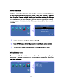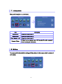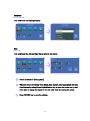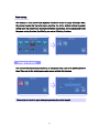
1
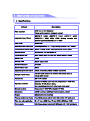
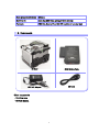
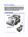
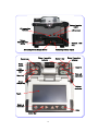
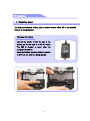
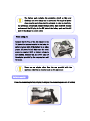
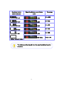
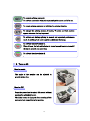
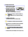
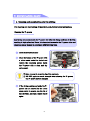
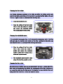
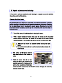
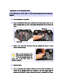
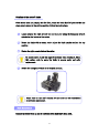
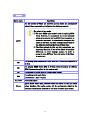
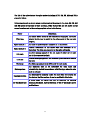
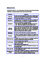
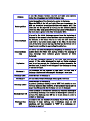
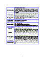
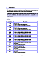
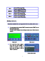
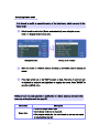
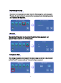
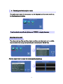
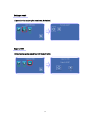
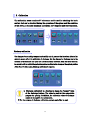
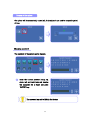
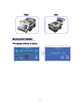
User Manual Optical Fiber Arc Fusion Splicer SWIFT S3 Read this service manual carefully before running S3. Table of Contents I . For Your Safety 3 II . Specifications and Components 7 1. Specifications 7 2. Components 8 3. Preparations for splicing 9 10 III. Product Description 1. External appearance of S3 10 2. Arc fusion splicing assembly 12 IV . Operation 13 1. Supplying power 10 13 V . Menu Description 10 16 1. Function buttons 16 10 2. Turning on S3 10 17 3. Installing the protective sleeve loader / cooling tray 18 10 4. Cleaning optic fibers 10 18 5. Inserting fiber into the protection sleeve 19 10 6. Cleaning and removing the skin of fiber 19 7. Cutting an optic fiber 19 10 8. Placing the fiber in the splicer 20 10 9. Splice procedure 21 10 10. Removing spliced fiber 25 10 11. Installing the sleeve on the sleeve heater 25 10 12. Heating the protection sleeve 10 26 10 27 VI . Maintaining Splice Quality 1. Cleaning and examination prior to splicing 10 27 2. Regular maintenance and cleaning 29 10 10 32 VII. Menu 1. Splice menu 32 10 2. Heater menu 43 10 10 1 3. Option 47 4. Checking splicing result 51 10 5. Calibration 53 10 6. Electrode 10 60 7. Locking menu 63 10 8. Settings 63 10 9. Information 70 10 10 72 IX. Error Messages 1. FIBER DIRTY 72 10 2. REPLACE POSITION 72 10 3. TOO LONG FIBER 72 10 4. FIBER OVER ANGLE 73 10 5. LOSS LIMIT OVER 73 10 6. FIBER THIN ERROR 73 10 7. FIBER THICK ERROR 74 10 8. CORE BUBBLE 74 10 10 75 X. How to deal with splicing problems 1. When the splice loss is too high 75 10 2. Abnormal operation of arc fusion splice 76 10 10 77 XI. Q&A 1. Power 77 10 2. Splice operation 78 10 3. Operation of the tube heater 79 10 4. Maintenance 80 10 5. Other settings 80 10 XII. Warranty Period and Contact Information 1. Warranty period and services 81 10 10 81 2. Before sending the arc fusion splicer to us, 81 10 3. Information required for repair 81 10 4. Transport 82 10 5. Repair 82 10 10 Product Warranty 83 10 2 Ⅰ. For Your Safety Swift S3 has been designed and produced to maximize the user’s convenience for both outdoor and indoor works, so its operation is easy and simple. However, we strongly recommend our customers to read this service manual carefully prior to running the device in order to prevent any accident and breakdown because improper handling of Swift S3 may cause serious danger. This service manual provides all the necessary information to ensure splicing safely. � Keep this service manual with the device at all times Ilsintech co. lt is not liable for any personal injury, physical loss and damage to device caused by inappropriate use or remodeling of the equipment. Warnings Please, turn off the power of the device immediately and contact Ilsintech co. ltd if any of below mentioned incidents occurs while operating the machine. � Fumes, bad odor, noise or overheating � Liquid or foreign substances falls into the device � The arc fusion splicer is dropped or damaged Use the power cord provided with the device. Using an inappropriate AC power cord may cause fire, electric shock or injury. DO NOT touch the electrode when the power of S3 is ON. The high voltage and temperature may cause electric shock or burn. Connect the AC power cord to the battery charger provided with the device and wall outlet. Check to ensure no dust or foreign substance on the AC plug electrode before connecting it. Unsafe connection may cause the occurrence of fumes, fire or damage to the device resulting in fire or serious injury or death. 3 Warnings Apply correct voltage. The correct input AC power to the adapter is AC 100-240V and 50-60Hz. Examine the input AC power before applying. Applying incorrect AC power could result in electric shock, equipment breakdown, serious injury or even death. Abnormally high AC voltage or irregular frequencies are often generated by AC generator; hence it is necessary to check the AC output power with a circuit tester. Since abnormal high voltage and frequencies may result in serious electric shock, injury, death or damage to the equipment, it is important to regularly check the operation status of the generator before use. DO NOT excessively pull, amend, misuse or apply heat to the AC power cable provided by the company. Using a damaged power cable may result in fire or injury. Connect 3-core Ac power cord. DO NOT use 2-core, cable and plug. DO NOT touch the AC plug, AC power cable or the arc fusion splicer with wet hands. It may cause an electric shock. . DO NOT disassemble the AC adapter, battery or the arc fusion splicer. Any amendment or changes of S3 may cause fire, electric shock or injury. When using an external battery pack, follow instructions below. � Using improper external battery may cause fumes, damage to the device, burn, serious injury or even death. � DO NOT throw the battery into fire or a trash incinerator. � DO NOT charge the battery near flame or fire. � DO NOT excessively or apply physical shock to the battery. � If the batter is not fully charged or green LED is not turned on in about six hours, stop charging immediately and contact Ilsintech co. ltd. DO NOT put any object on the AC adapter while it is being charged. Use the adapter (S311) and battery pack (S313) that are provided by the company at all times. Using a different type of battery pack may cause fumes, fire, and damage to the device, injury and death. 4 Warnings Use the battery adapter provided by the company at all times. DO NOT use other type of AC power cord. Make sure that no short circuit is made in the terminal of the AC adapter (S313) and the battery. Excessive electric current may cause damage to the machine and injury. DO NOT run S3 in an environment there is flammable liquid or toxic gas. The electric arc of the arc fusion splicer may cause fire or explosion. DO NOT clean S3 using compressed air or gas. Check the condition of belt to ensure that it has no damaged or worn out parts before transporting the carrier case using the belt. If the carrier case is dropped due to worn out belt, it could damage the machine or people could get hurt. Make sure to wear protective glasses while performing splicing works. If fiber fragments come into contact with the eye or skin, it can be extremely dangerous. DO NOT operate the arc fusion splicer at a high temperature or near heat, otherwise injury or damage to the device may occur. Take extra caution when handling the heater part whose surface is extremely hot. DO NOT touch it by hand and make sure nothing contact it. : DO NOT TOUCH : EXTREMELY HOT : : DO NOT SPARY FREON GAS 5 Cautions DO NOT touch the tube heater or the protection sleeve during or immediately after heating them. The hot surface may cause injury. DO NOT place S3 in an unstable or unbalanced place. The machine may fall, causing injury or damage to the machine. S3 has to be precisely adjusted and aligned. DO NOT allow the unit to receive a strong impact. Use the supplied carrying case for its transportation and storage. The carrying case protects S3 from breakage, moisture, shake and shock during storage and transportation. Replace the electrode in a timely manner and maintain it as instructed below; � Use only a specified electrode. � Place a new electrode in the correct position. � Replace the electrodes as a pair. If the user fails to follow the above instructions, it may cause abnormal arcdischarge, resulting in damage to the machine or degradation in splicing performance. Use no chemicals other than ethyl alcohol (96% or greater) to clean the objective lens, V-groove, windshield mirror, LCD monitor and body of the machine. Otherwise, blurring, discoloration, damage or performance deterioration may occur. S3 requires no lubrication. The use of oil or grease may degrade its performance and damage to the equipment DO NOT store the device in a place where temperature or humidity is high. Damage to the machine may occur. The technical examination of S3 must be carried out by a qualified engineer; otherwise, fire or electric shock may occur. If any problems occur, contact Ilsintech co. ltd for repair and maintenance. 6 Ⅱ. Specifications and Components 1. Specifications Subject Fiber alignment Description IPAS core to core alignment (Image pattern analysis alignment system) SM(ITU-T Applicable type of fibers G.652), MM(ITU-T G.651), DS(ITU-T G.653), NZDS(ITU-T G.655) EDFA, EI980, Splicing available with different type fiber(SM/MM), ITU-T G.657 Fiber count Single fiber Applicable fiber dimensions Cladding diameter: 80 ~ 150㎛, Coating diameter: 100 ~ 1000㎛ Fiber setting and cleaved length 250㎛: 8~16mm, 900㎛: 16mm(Application Holder: 8mm) Splicing modes Splice mode: 100, Heat mode: 50 Typical Splice Loss SMF: 0.02dB, MMF: 0.01dB, DSF: 0.04dB, NZDSF: 0.04dB Return Loss >60dB Splicing Time Splice: Typical 9sec Splice loss estimate Available Sleeve heating time 35sec Applicable protection sleeve 40mm, 60mm(fiber), 28mm or 32mm (connector) Storage of splice result Tension test The last 9,500 results to be stored in the internal memory. (Image 9,500 results) 2N / 4.4N (Option) Altitude: 0~5,000m above sea level, Temperature: -10℃~50℃, Operating condition Humidity: 0~95%, Wind: 15m/s, non-condensing, dust proof, water proof, shock proof Storage condition Temperature: -40℃~80℃, Humidity: 0~95% Dimensions 135(W)x163(L)x146(H)mm (Include monitor, rubber) Weight 2.0kg(Include battery 2.5kg) Viewing method and display Two CMOS cameras and 4.3" color LCD monitor with touch panel Fiber view and magnification X or Y view: 300X, X and Y view: 300X, 187X(Zoom 700X) Power supply DC Lithium polymer battery(14.8V, 6000mAh), 100 ~ 240V AC Adapter 7 No.of splice cycles with battery 250cycle Electrode life More than 3,000 times splicing without exchange Terminals USB, RCA, External Power(DC 12V Available for car cigar jack) 2. Components S3 Body S313 Battery Pack S311 AC Adapter AC Cord Other components - Carrying case - Service manual 8 3. Preparations for splicing Fiber types 0.25 mm 0.9 mm Basic sleeve Fiber protection sleeve 40 mm long 60 mm long Micro Sleeve 20 mm 25 mm 34 mm 45 mm Fiber stripper Fiber Stripper Fiber cutter [CI-03] Fiber cutter Fiber holder [Standard] Fiber holder [FTTH] Cut length: 16 mm (fixed) Cut length: 10 mm (Fixed) Cut length : 5 ~ 20 mm(Variable) Cut length: 5 ~ 20 mm(Variable) Use cotton or gauze with alcohol dispenser. Fiber cleaning tools Ethyl alcohol ( > 96%) 9 Ⅲ. Product Description Optical fiber arc fusion splicer Swift S3 has been designed for splicing various types of optical fiber using IPS system technology. In order to meet the work conditions of both inside and outside, it is small, light and easy to operate maintaining very low rate in splice loss and fast splice capacity. Users have to read carefully the service manual for the maximum use of S3. 1. External appearance of S3 Windshield Cover Battery Monitor (Touch panel) 10 External monitor output PC connection terminal A/S terminal Battery disengagement button Upgrade USB Port Remaining battery display button Power lamp Remaining battery display Heater 1 operation indicator Heater 1 key Heater 2 operation indicator Power switch Heater 2 Arc discharge key Rest and return key Menu key Screen change key Perform arc fusion Touch screen Return & cancel key Enter Cursor Key 11 2. Arc fusion splicing assembly Y axis camera Camera light Upper electrode cover Cover to fix left fiber Upper electrode Cover to fix right fiber X axis camera Lower electrode cover Night light Lower electrode X Reflection mirror Windshield Cover V-BLOCK Lever V-BLOCK vV V-BLOCK R L Y Reflection mirror Heater cover Cover close lever Heater 1 Central heater Heater 2 12 Ⅳ. Operation 1. Supplying power The high performance battery and its power adapter allow S3 to be operated while it is being charged. Charging the battery Connect the adapter to the DC jack of the battery and the AC cord to a wall AC outlet. The LED is changed to green when the charging is completed. Since the floating charging method is applied to S3, it can run while it is being charged. 13 The battery pack includes the protection circuit so that over discharge and over charge can be prevented. The supply of power stops once the protection circuit is activated. In order to deactivate the protection circuit and resume feeding power, wait about 10 seconds and connect the DC plug to the DC jack of the battery pack and the AC cord of the charger to a wall outlet. When using AC Connect the DC Plug of the AC adapter to the DC jack of the battery installed in the body. An amber or green light of the battery is on when proper AC power is fed. Make sure the rated power is supplied. 250V or higher voltage is not allowed. Connect the AC power cable of the adaptor provided by the company to a wall AC outlet. Never use an adapter other than the one provided with the machine; otherwise an incident such as fire may occur. Battery capacity Press the remaining battery display to display the remaining amount of battery 14 Remaining battery Remaining battery amount display amount (Monitor) (LED) (5 bars) 5 LED (4 bars) 4 LED (3 bars) 3 LED (2 bars) 2 LED (1 bar) 1 LED 1LED blinks Percentage 80 ~ 100% 60 ~ 80% 40 ~ 60% 20 ~ 40% 10 ~ 20% Within 10% (Battery indicator blinks) The battery must be charged when the remaining battery is as low as one bar. 15 Ⅴ. Menu Description 1. Function buttons To turn the power on and off. When the switch is pressed and held for about 0.5 second, the power and monitor are turned on and the indicator next to the switch is changed to green. When the switch is pressed and held for about one second, the indicator and power are turned off. To move the cursor to left. The monitor becomes darker if it is pressed on the initial screen. In addition, it is used to control the movement of fiber and adjust the camera focus in manual mode. (Refer to the manual mode instruction for more detailed information). To move the cursor to right. The monitor becomes brighter if it is pressed on the initial screen. In addition, it is used to control the movement of fiber and adjust the camera focus in manual mode (Refer to the manual mode instruction for more detailed information). To move the cursor upward. In manual mode it is used to select each motor (Refer to the manual mode instruction for more detailed information). To move the cursor downward. In manual mode it is used to select each motor (Refer to the manual mode instruction for more detailed information). To open the menu screen To cancel a selection command and return it. To move to previous level on menu screen or cancel a setting in edit mode. To confirm a setting and enter function To move to next level on menu screen or confirm a setting in edit mode. 16 To execute splicing command. To activate next action when the separated performance med is in use. To cancel splicing command or initialize the splicing function. To change the splicing screens. X screen, Y screen and both screens appear whenever the key is pressed. To activate arc during splicing in manual and separated performance mode. In addition, it is used to perform additional discharge. To activate the sleeve heater 1. When it is on, the left red indicator is turned on and heater is turned if the key is pressed one more time. To activate the sleeve heater 2. . 2. Turn on S3 Monitor angle The angle of the monitor can be adjusted to provide better view. Monitor ON Press the power key for about 0.5 second without opening the windshield cover. The initial screen is displayed after resetting all the motors to their respective initial position. 17 Initial Screen It is important to choose a right splice mode to ensu re an accurate splicing result. The current splice mode is displayed on the initial page. A right heater mode must be selected to heat the protection sleeve. The current heater mode is displayed on the initial page. Display battery status Display USB memory connection Display PC connection � Press MENU key to change splice mode on the initial page. � The splice mode and heater mode are displayed on the screen. 3. Installing the protective sleeve loader / cooling tray Pull out the protection sleeve loader and inset it into the right or left groove. Insert the cooling tray into the groove at the rear side of the heater. 4. Cleaning optic fiber Clean carefully the optic fiber with a piece of soft cloth or cotton swab soaked in alcohol. Fine dust on the coated surface of the fiber can cause the break off or decrease once the fiber is set inside the protection sleeve. 18 5. Inserting fiber into the protection sleeve Insert the fiber into the protection sleeve. Sleeve Fiber vV vV 6. Cleaning and removing the skin of fiber Remove the skin of the fiber about 4 cm from the tip using a stripper and then, carefully clean the fiber with a piece of soft cloth or gauze soaked in alcohol. Use high quality ethyl alcohol with higher than 96% purity . 7. Cutting an optic fiber . 1 Place the stripped fiber on the cutter and check the desired length to cut. 19 2 Pull down and press the cutting level to cut the fiber. 3 Lift the cutting lever and take out the cut fiber. 4 Remove the cut fiber fragment and dispose it in a proper container. Please refer to the user’s manual of the cutter for more detailed information about the operation of the cutter. 8. Placing the fiber on the splicer 1 Open the windshield and holder of the fixer. 2 Place the fiber between the Vgroove and the electrode. V-Groove Electrod e vV � If the coated part of the fiber is bent, place the bent part downward. � Make sure that the tip of the prepared fiber does not contact other object. 3 Hold the fiber with a hand so that it does not move and close the fixer holder. 4 Place the other fiber in the same way as 5 Close the windshield cover. 20 3 9. Splice procedure The condition of the fiber can be observed via the image processing system installed in Swift S3. However, an examination with operator’s naked eyes is necessary to ensure better splice result. 1 The fibers installed in the splicer move toward each other. The moving fibers can stop at precise positions at which point splicing can be carried out after completing a discharge for cleaning. Then, the cut angle, physical condition of the tip area and dust existence need to be checked. If the measured cut angle is bigger than the preset limit value or any damage to the fiber is discovered, an error message appears on the screen and the splice process stops. If no error message appears on the screen, examine the condition of the cross sections with your eyes based on following figures. Any fiber that has similar condition to any of below figures has to be removed and a new fiber must be placed. These general defects can cause a wrong splice. Cracked 2 Broken Tilted The fibers whose examination has completed are arranged core to core or clad to clad. The measured values of clad axis deviation and core axis deviation can be displayed on the screen. � It is possible to set the fibers not to be arranged after checking the cut angles. � The maximum limit of cut angle can be changed. � Press SET key to proceed to the next step ignoring the error message about the cut angle. � It is possible not to display the cut angle and the deviations of clad axis and core axis during arc fusion. 21 3 Discharge is carried out to perform splicing the fibers after completing the arrangement of the fibers. The discharge is initiated when the ARC key is pressed after completing the arrangement in non-continuous operation mode. 4 The splice loss value is measured after completing arc fusion and displayed on the screen. The loss value is affected by error elements. And, these elements also influence the estimation and computation of the value. The computation of the loss value is based on such clear measurement Enlarge image Re-discharge Reduce image factors as MFD. Save image If the measured cut angle or computed loss value is greater than the preset limit, an error message appears on the screen. Also, an alarm can be triggered by the discovery of an abnormal condition of the spliced part including too thick or thin area or bubbles. Even if an error message does not occur, it is recommended to perform the arc fusion process again if the result on the screen does not look good enough when examining it with naked eyes. � Sometimes, the spliced area can seem fatter or larger than other part. This is normal situation and does not affect the splice loss. � Please refer to relevant parts for more information about changing the limit values of computed splice loss or cut angle. The splice loss can be corrected and improved in some cases via conducting additional arc fusion. Press ARC key to conduct additional arc fusion, which will perform the computation of splice loss value and check the condition of the spliced area. However, in some cases, the splice loss can be aggravated by performing additional arc fusion splicing; hence the operator can set the additional discharge off or limit the number of discharge. 22 Growth of splice loss: causes and corrective measures Symptoms Cause Corrective measures Core axis deviation Dust on the V-groove or holder Clean the V-groove or holder Core angle Dust on the V-groove or holder Clean the V-groove or holder Bad condition of fiber’s tip Check the performance of fiber cutter. Core deformation Dust on the V-groove or holder Clean the V-groove or holder Irregular core Bad condition of fiber’s tip Check the performance of fiber cutter. Too low initial discharge or too short initial discharge time Increase the initial discharge or initial discharge time Too low discharge Too low discharge Inconsistent MFD Check the performance of fiber cutter. Clean carefully the fiber or There is still dust after cleaning increase the discharge duration or discharge for cleaning. for cleaning. Burned Bad condition of fiber’s tip Bubbles Bad condition of fiber’s tip Check the performance of fiber cutter. Too low initial discharge or too short initial discharge time Increase the initial discharge or initial discharge time Separation Increase the duplicated area. Too much initial discharge or too Decrease the initial discharge or long initial discharge time initial discharge time 23 Thick Thin Fiber is too long. Decrease the duplicated area. Incorrect discharge amount Conduct discharge calibration Some discharge elements are Adjust initial discharge, time not correct Line and duplicated area. Some discharge elements are Adjust initial discharge, time not correct and duplicated area. A vertical line appears on the spliced area sometimes when splicing multimode fibers or not similar fibers (i.e. whose diameters are different). However, it does not affect the splice loss or the splice quality including tensile strength. Saving splice results The splice result can be saved and the procedure is as follows; Total 9,500 results can be recorded and the 9,501th result will be warren on the line of the 1st result. How to save the splicing result image (a note cannot be entered) The splicing result is saved automatically, after completing splicing and in the event of an error, it will not be saved. In case of saving the completed splicing image, tap the camera icon which is in the lower middle of LCD or press the enter key. 24 10. Removing the spliced fiber 1 Open the sleeve heater cover. 2 Open the windshield cover. 3 Hold the left fiber with your left hand from the edge of the windshield and open the left fixer cover. Keep holding the fiber until transporting it to the tube heater. 4 Open the right fixer cover 5 Hold the right fiber and remove the spliced fiber from the splicer. 11. Installing the sleeve on the sleeve heater Place the arrow of the sleeve heater to the center of the protection sleeve. Slowly move the spliced fiber from the light until it reaches to the left hand at the edge of the tube heater. Place the protection sleeve in the middle of the tube heater. Make sure that the splice area is placed in the middle of the protection sleeve. 25 12. Heating the protection sleeve 1 Move the fiber inserted into the protection sleeve to the middle of the tube heater. 2 Place the fiber covered by the protection sleeve on the tube heater. Apply tension to the fiber downward so that the tube heater cover is closed automatically When placing it on the tube heater (it applies to only the heater 1). � Make sure that the spliced area is placed in the middle of the protection sleeve. � Place the supporting part inside the protection sleeve toward bottom. 3 Press HEAT key to start tube heating. LED of HEAT (red) is turned off when tube heating is completed. Tube heating stops if the HEAT key is pressed again during heating. 4 Open the heater cover and remove the fiber that has been protected from the heater. Apply tensile force to the fiber while removing it from the heater. The protection sleeve may have been attached to the floor of the heater. Use a cotton swab when removing the sleeve from the heater. 5 Check to ensure there is no bubble, fragments or dust in the sleeve at all times. 26 Ⅵ. Maintaining Splice Quality 1. Cleaning and examination prior to splicing For cleaning and maintaining of important parts, follow below instructions. Cleaning the V-groove Any foreign substances inside the V-groove will affect the fixing condition of the fiber, resulting in high splice loss. Hence, it is important to examine the V-groove often and clean in a regular manner in accordance with following ways. 1 Open the windshield cover 2 Clean the bottom of the V-groove with a cotton swab soaked in alcohol and remove the remaining alcohol inside the V-groove with a clean and dry V-groove cotton swab. � Make sure not to touch the tip of the electrode. � DO NOT apply too much strength when cleaning the V-groove. The V-groove may be damaged. 3 If the foreign substances inside the Vgroove are not removed by the cotton swab soaked in alcohol, use the tip of the cut fiber. And then, repeat step 2 again. 27 Cleaning the fiber holder Any foreign substances remaining in the holder can affect the holding position and result in bad splice result. Hence, it is important to examine the fiber holder often and clean in a regular manner in accordance with following ways. 1 Open the windshield cover. 2 Clean the surface of the fiber holder with a cotton ball soaked in alcohol and remove the remaining alcohol with a clean and dry cotton swab. Holder Cleaning the windshield mirror If the windshield mirror gets dirty, it will decrease the transparency level of the fiber path and cause the improper core position of the fiber, resulting in high splice loss rate. Clean the mirror in accordance with following instructions. 1 Clean the surface of the fiber holder with a thin cotton ball soaked in alcohol and remove the remaining alcohol on the mirror surface with a clean and dry cotton swab. 2 The windshield mirror must be kept clean without a line, scratch or stain. Cleaning the fiber cutter The performance of cutting fibers can be deteriorated if the blade or clamp pads of the fiber cutter are contaminated. In addition, the contamination of the fiber surface or tip can cause high splice loss. For this reason, it is important to clean both the blade and clamp pads of the cutter with a cotton ball soaked in alcohol. 28 2. Regular maintenance and cleaning It is crucial to perform examination and cleaning in a regular manner to maintain the splice quality of the device. Cleaning the object lenses The contamination of the object lens surface may cause incorrect observation of the core position, resulting in high splice loss and abnormal performance of the device. Therefore, the two object lenses have to be cleaned in regular manner. Otherwise, the dust will settle on the surface continuously and it may not be removed in the end. Clean them as instructed below. 1 Turn off the power of the device prior to cleaning the lenses. 2 With an alcohol-soaked soft cotton swab, clean the (X axis and Y axis) lenses drawing spiral in form from the middle to the edge of the lenses. Remove remaining alcohol on the surface of the lenses with dry and clean cotton ball. � Make sure to remove the electrode before cleaning the object lenses. � Be careful not to touch the tip of the electrode when cleaning the object lenses. 3 The surface of the lenses must be kept clean without a line, scratch or stain. 4 Check to ensure there is no line, scratch or stain on the surface via the monitor screen after turning on the power. The condition of the lens surface must be examined on the X and Y screens, changing the screen by pressing X and Y keys. 29 Replacement of the windshield mirror If you cannot clean the mirror clearly or remove stains completely, the mirror has to be replaced. 1 Turn of the power of the splicer 2 Open the windshield cover and, as shown in the below figures, push out the mirror case hook until you hear a click sound. Lift the mirror lock and detach the mirror. Mirror lock vV Mirror hook vV 3 Insert a new mirror into the mirror lock and assemble the parts in reverse manner of disassembling. Make sure that the surface of the mirror has been properly inserted. If it is not properly placed, the central line of the fiber cannot be observed accurately. 4 Clean the mirror. 5 Turn on the power and examine if there is any line, scratch or stains on the surface via the monitor screen. The condition of the lens surface must be examined on the X and Y screens, changing the screen by pressing X and Y keys. 30 Rotation of the cutter’s blade If the cutter does not properly cut the fiber, rotate the blade by 1/16 point so that the sharp area is placed at the cutting position. Follow the instructions. 1 Loosen slightly the right wrench bolt on the cutter using the hexagonal wrench attached at the bottom of the cutter. 2 Rotate the blade with a cotton swab; adjust the blade number to face the top position. 3 Fasten the right wrench bolt on the cutter. Be careful not to touch the edge of the blade when rotating it. Use a thin cotton swab to move the blade to ensure easier and safer replacement. 4 Return the hexagonal wrench to its original position. Please refer to the user’s manual of the cutter for the information about blade replacement. Blade Replacement Replace the blade when all the 16 positions of the blade have been used. 31 Ⅶ. Menu 1. Splice menu The most optimized splice settings for the accurate combination of fibers consists of following factors for splicing. Here, the splice factors depend on the combination of and differences between fibers. � Factors for adjusting discharge and heating � Factors for computing the estimated loss � Factors for adjusting the arrangement and splice process � Maximum tolerance values before triggering an error message. The types of the optimized splicing factors for the best combination of fibers have already been saved in the splicer. These information saved as database can be used by copying to the user program part. These factors can be amended for a better combination of fibers. 32 Database Splice mode Description The key profiles of fibers are observed and the fibers are automatically spliced. Users are not allowed adjusting the discharge amount. Key points of auto mode � The basic NZDS splice mode is used for splicing NZDS fibers. However, it recommends the most optimized splice mode selected for the NZDS fiber in question to ensure the best result. It is because the changes in the nature of the fiber. The most optimized splice factor is the difference between the types of NZDS fiber. � The fibers placed at right and left, respectively, are separately identified. If one of the fibers is identified differently, an error message appears. In order to cancel it, press SET key. Then, the splice of the fibers is carried out. AUTO SM NZ DS MM AT1/AT2 For splicing basic single mode fibers. MFD is 9~10um at the frequency of 1310nm. For splicing NZDS fibers. MFD is 9~10um at the frequency of 1550nm. WDM fibers can be spliced in this mode as well. For splicing DS fibers. MFD is 7~9um at near 550nm. For splicing multi mode fibers. Core diameter : 50.0 ~ 62.5um Attenuation splice Splice modes other than presented above are saved in the arc fusion Others splicer database. New splice modes will be continuously added to the database. Please contact Ilsintech for the latest available splice modes. 33 Selection of a splice mode Select the most appropriate splice mode depending on the type of the fibers to be spliced. 1 In ready status, press “MENU” or touch “MENU” icon on the screen to call menu. The splice mode appears when the splice menu is selected or clicked using the cursor. Ready status 2 Menu screen Move the selection bar up and down using arrows and enter to select. Or, simply tap the desired mode on the screen and tap “Select” again. Splice mode setting Press ESC key or tap Close on the screen to end the splice mode selection menu. 34 Generation and deletion of a splice mode How to generate a splice mode Tap “New” on the screen. Move to the type of fiber that is about to use and press “ENTER”. Or, tap the mode and “OK” on the LCD. Splice mode setting Selection of the to-be-generated mode The generated splice mode 35 How to change the splice mode Tap “Replace” on the screen. Move to the type of fiber that is about to use and press “ENTER”. Or, tap the mode and “OK” on the LCD. Splice mode setting Selection of the mode to be changed The modes that are generated and listed after number 20 on the list can be changed. How to remove a splice mode Tap “Del” on the screen. Move to the type of fiber that is about to use and press “ENTER”. Or, tap the mode and “OK” on the LCD. Splice mode setting � Splice modes from 1 to 20 on the list cannot be deleted. � Mode number 1 is automatically selected when a splice mode is deleted. 36 Editing reference or splice modes The splice factors belonging to each splice mode can be modified. The two of most important factors – discharge and time – can be amended as follow; 1 Press the right direction arrow to display the splice mode edit on the splice mode setting. Or tap “Edit”. Splice mode setting 2 Move the cursor to the element that needs to be changed by pressing the up and down keys or tapping the screen. 3 Press right arrow or tap “Edit” to select an element. The values can be adjusted using right or left direction key or tapping the screen in each element edit screen. Press “ENTER” to save the amended value. Splice mode setting Changing the value 화면 37 The list of the splice factors for splice modes including AUTO, SM, DS, MM and NZ is presented below. Only some elements as shown below are displayed on the screen in the Auto, SM, DS, MM and NZ modes for the sake of easy operation. Other factors that are not shown on the screen have been set to the most appropriate values in the factory. Factor Description The splice modes saved in the database are displayed. The mode Fiber type selected by the user is copied to the splice mode in the user side program. Splice method 1 Splice method 2 Cut angle Loss rate Discharge The titles of splice ways are displayed as 11 characters. Detailed description of the splice ways are described as 11 characters. The titles are presented in the splice edit mode. An error message appears if the cut angle of either left or right end of fiber exceeds the limit. An error message appears if the estimated splice loss value exceeds the limit. The discharge amount is set differently for each mode. The discharge time is set differently for each mode and Discharge time automatically decided in accordance with fiber type when the auto mode is selected. Cleaning duration The discharge for cleaning occurs for short time for burning the fine dust on the fiber surface. It can be modified in this factor. In some cases, the splice loss can be improved by applying Re-discharge time additional discharge. And the duration of the re-discharge can be modified here. 38 Editing splice mode This function allows you to set multiple splice modes that meet the work environment. Description of various parameters and their uses are explained below. Parameters Description Fiber type The user can select appropriate modes from the default splice modes and edit the copy of the splice modes saved in the database. Mode title 1 The title can be composed of 1 to 11 characters. Mode title 2 It consists of up to 11 characters and is used to provide more detailed information. It can be found in the [Splice Mode] menu. Arrangement It is used to set the fiber arrangement methods “Core” : Fibers are arranged to the core positions of both fibers. “Clad” : Fibers are arranged to the center position of clad. Left focus Right focus It allows focusing during the observation of fibers. The focal plane moves to near core and away from the core by increasing and reducing the figure, respectively. Auto focusing is recommended. Fibers in the left and right position are focused independently. It works when different types of fibers are spliced. Eccentricity adjustment It is used to set the offset ratio of axes when arranging fibers. Auto power The effect of discharged amount is maximized as the fibers have been arranged the most closely to the core center and fewer errors occur. Tensile force test If [Tensile force] is set to “ON”, a test is carried out during the opening the windshield after splicing or pressing SET. Cut angle range It sets the tolerance range of cut angle. An error message appears when a measured right, left or both angles exceed the range. Loss rate It sets the error range of estimated loss. An error message appears when the estimated loss is greater than the maximum range. Fiber angle limit An error message appears when the bending value of the spliced two fibers exceeds the set limit. Discharge time for cleaning A short period of discharge is performed to remove the fine dust on the fiber surface as setting the distance between the cross sections of fibers. The duration of the discharge is set here. 39 Distance It sets the distance between the left and right cross sections during the arrangement and initial discharge time. Center position It sets the position of the fibers to the center of discharge. When the MFD of the left and right fibers are inconsistent, the MFD can be spliced by melting the fiber with smaller MFD. The splice loss can be improved by moving the set distance position toward the fiber with larger MFD from the center of discharge so that more heat is given to the fiber with smaller MFD. Initial discharge It is set by the initial discharge amount from the beginning of discharge to the moment before the fibers start moving forward. At this moment, if the initial value is too low, the axis’ offset can occur due to bad cross section angle of the fiber. On the other hand, if the initial value is too high, the fiber can be burned out or shaped round, resulting in aggravating the splice loss. Initial discharge time It is set by the initial discharge time beginning of discharge to the moment before the fibers start moving forward. The meaning of [long discharge time] indicates greater [amount of initial discharge]. Duplication It sets the duplication amount of the fifers from the forward amount. If [the initial discharge] is weak or [initial discharge time] is not long enough, the [duplication] needs to be smaller. On the other hand, it should be set to bigger if the discharge is strong or the time is longer. Discharge 1 The discharge can be adjusted by two steps. The first step is discharge 1 and second is discharge 2. Discharge 1 is set here. Discharge time 1 Discharge 2 It sets the time of discharge 1. It is the second step of discharge. Discharge 2 is set here. Discharge time 2 It sets the time of discharge 2. In general, [Discharge time 2] is set to “OFF”. It is possible to set a very long discharge time; however, if the discharge time 1 and 2 is longer than 30 seconds, the discharge unit can be damaged. Discharge time ON It sets discharge to ON and OFF alternatively while the discharge 2 is performing discharge. The duration of discharge 2’s operation is set here. The discharge time ON has to be set always in order to conduct re-discharge. Discharge time OFF It is used to set the duration of discharge 2’s off time. When the discharge 2 stops working, the re-discharge stops as well sometimes. Set this parameter to “OFF” if a continuous redischarge is required. 40 Re-discharge time It sets the re-discharge time. It automatically sets the re-discharge to discharge the same amount as [Discharge 2] in [Splice Mode Edit]. If discharge 2 is set to ON and OFF, the re-discharge is automatically set to ON and OFF as well. Attraction splice The splice loss rate increases sometimes when the fiber becomes thinner. The attraction splice is set to “ON”. The three factors of the attraction are decided by following three parameters. Attraction waiting time It sets the time between the last moment of fiber’s moving forward and the initiation of attraction. Attraction speed It sets the speed of fiber attraction. Attraction time It sets the time of attraction. Estimation modes Left MFD Right MFD Deviation Core arrangement proceed Core irregularity Inconsistent MFD “OFF”, “Core” or “Clad” “Clad” is selected during the MMF splicing. One of these can be chosen as a method to estimate the splice loss. The MFD of left and right is set. The estimated splice loss for left and right MFDs has to be computed, respectively. It refers to the sum of the initially measured splice loss value and increased loss value. When splicing special types of fiber or different kinds of fiber, a high splice loss can occur even under an optimized discharge condition. The minimum value of the actual splice loss has to be set in order to accord the actual splice loss value with estimated splice loss value. Core arrangement proceed, Core irregularity and Inconsistent MFD affect the measurement of splice loss. If the estimated mode is set to “OFF” or “Clad”, the core step, core irregularity and MFD defect are automatically set to “OFF”. If the splice estimation that is considered to be certain is required to be amended, it is modified using Core arrangement proceed, Core irregularity and Inconsistent MFD. 41 Entering mode title / notes / password The list of characters is displayed underneath when choosing the mode title, note or password. 1 Select desired characters using up, down, left and right keys or tapping each character on the screen. Then, press “ENTER” to confirm the selections. 2 Confirm the selection of characters by pressing “ENTER” or tapping “ ” on the screen. Attenuation splice The attenuation mode is designed to attenuate the focal point of splice by intentionally generating the deviation of axes; it consists of two types. One of “Attenuation 1(SM)”, “Attenuation 1(DS)”, “Attenuation 2(SM)”, “Attenuation 2(DS)” and “Attenuation 2(MM)” has been selected by default. [Attenuation 1] mode [Attenuation 1] performs optical fiber splicing by intentionally utilizing the deviation of the core axis. [Attenuation 1] displays the estimated splicing loss whose value does not necessarily indicate the accurate loss but a value for reference purpose only. Use a power meter to measure an accurate value of splicing loss. 42 2. Heater menu The heater mode consists of 12 different modes. The operator needs to choose the most appropriate heater mode prior to using the protection sleeve. The protection sleeve type uses the tube heat functions. The reference of this mode can be found in the database. Any contents required can be copied to and amended in the user’s program. Database Parameters S-160 60mm S-140 Description Ilsintech S-160 A mode to heat the 60mm macro sleeve. A mode to heat the standard 60mm macro sleeve. Ilsintech S-140 A mode to heat the 40mm macro sleeve. 40mm A mode to heat the standard 40 mm macro sleeve. 25mm A mode to heat the standard 25 mm macro sleeve. 20mm A mode to heat the standard 20 mm macro sleeve. 45mm A mode to heat the standard 45 mm macro sleeve. 34mm A mode to heat the standard 34 mm macro sleeve. 25mm A mode to heat the standard 25 mm macro sleeve. 40mm A mode to heat the standard 40 mm macro sleeve. 34mm A mode to heat the standard 34 mm macro sleeve. 25mm A mode to heat the standard 25 mm macro sleeve. 20mm A mode to heat the standard 20 mm macro sleeve. S09 S09-C S20 S30 Ilsintech S09 A mode to heat the 45 mm sleeve. Ilsintech S09 Connector Type, A mode to heat the 22 mm sleeve. Ilsintech S20 A mode to heat the 45 mm sleeve. Ilsintech S30 A mode to heat the 45 mm sleeve. 43 Ilsintech S30 Connector Type S30-C A mode to heat the 32 mm sleeve. Ilsintech LC09/20 Connector Type LC09/20-C A mode to heat the 25 mm sleeve. Ilsintech ST09 Connector Type ST09-C A mode to heat the 28 mm sleeve. Ilsintech ST30 Connector Type ST30-C A mode to heat the 36 mm sleeve. Selecting a heater mode Select a heater mode that is the most appropriate for the fiber protection sleeve in use. 1 The menu appears when pressing “MENU” is pressed or tapping “MENU” icon on the screen in ready mode. The heater mode is displayed when selecting the heater menu with the cursor or tapping it. Ready mode 2 Menu screen Use up and down keys to select a heater mode and press “ENTER” to confirm the selection. Or, select a heater mode by tapping it and tap “Select” to confirm it. Setting a heater mode 44 Modifying heater mode It is allowed to modify or amend the status of the tube heater, which are saved in the heater mode. 1 Select the edit mode in the [Heater mode selection] menu using the cursor. Click it to display [Heater mode edit]. Editing each element Setting heater mode 2 Move the cursor to a desired location by using up and down keys or tapping the screen. 3 Press right arrow key or tap “Edit” to select an item. The value of each item can be adjusted by using left and right keys or tapping the screen. Press “ENTER” to save the modified value. Editing of each item and generation / modification of a heater mode can be done in the same way as the splice mode (see page 35.) Parameters Description • To set the proper sleeve type Sleeve type • Entire heater mode list is displayed. • The program mode that the user intends to use can be copied or selected from the list. 45 • A heater mode title is displayed at the right bottom on the Method name 1 screen while splice and heating are in operation. • Up to 5 characters Method name 2 • The heater mode is described in the [Sleeve type] screen. • Up to 13 characters • It sets heater adjustment sequence. • LONG 1 : use of 60mm protection sleeve • LONG 2 : The 60 mm protection sleeve is also used for a fiber cut by 8 mm and coated with Ny. Heater adjustment • MIDDLE : The 40 mm protection sleeve is used. • MICRO 1 : The micro sleeve is used for a fiber with 900㎛ in external diameter. • Mircro 2 : The 34mm micro sleeve or a little longer sleeve. • Mircro 3 : The 34mm micro sleeve or a little shorter sleeve. • It sets the heating time. Heating time • The heating time is automatically adjusted depending on the surrounding temperature. The actual heating time could be longer or shorter than the set [Heating time]. • It sets the heating temperature. Heater temperature • Ny coated fibers are used by cutting them by 8 mm and [Heating temperature] has to be higher than 190°C. • It sets the ending temperature. • The sleeve can be removed after completing heating. • [Caution] If the ending temperature is higher, a buzzer sound Ending temperature occurs before the sleeve cools down. If the temperature is higher than 1,000°C, the fiber remaining in the splice point could be compressed and transformed when removing the sleeve from the tube heater. � Set the temperature below 200℃ when heating the standard sleeve. � DO NOT set the heating time longer than 120 seconds at high temperature (higher than 150℃). 46 3. Option There are 6 sub menus within the Option menu. It can be selected using left and right keys and “ENTER” or tapping the screen. Basic matters General settings for the entire modes of splice and tube heater operation can be done. 47 Setting menu Parameters Description Auto splice The splice process is performed automatically if “Auto splice” is checked. The splice process is carried out automatically when the windshield is closed after preparing fibers inside the splicer. Pause 1 The splice work stops after completing the adjustment of the distance between fibers when Pause 1 is checked. The splice process is continued when pressing SET button. The cut angle is displayed on the screen during the pause. Pause 2 The splice work stops after completing the arrangement of fibers when Pause 2 is checked. Discharge splice process is activated when pressing ARC button. Displaying data The user can choose whether to display the cut angle and axis deviation on the screen during splicing. Setting menu Parameters Description Cut angle If it is checked, the cut angles of left and right are measured and displayed on the screen. Axis deviation If it is checked, the result of measuring the arrangement deviation of core and clad is displayed on the screen. 48 Ignoring a splice error The user is allowed to choose whether an error is detected or not while the splice is in progress or it is completed. Setting menu Parameters Description Cleave If it is not checked, an error message appears when the cut angle set for each mode is exceeded. Loss If it is not checked, an error message appears when the loss limit for each mode is exceeded. Fiber Dirty If it is not checked, an error message appears if the surface of the fibers placed in the splicer is not clean. Thickness If it is not checked, an error message appears when the spliced area of the fiber whose splice is done is too thick or thick. Bubble If it is not checked, an error message appears when bubbles are generated in the core of the priced area. Fiber too long If it is not checked, an error message appears when too long fibers are placed in the V-groove. 49 Compensating discharge Air pressure and temperature are crucial factors for discharging when performing splice. Therefore, the user is allowed to choose whether to compensate the discharge depending on air pressure and temperature. TV Output The contents of the splicer can be printed via external visual equipment and applicable output methods can be determined. Arrangement mode When doing arrangement, the display of the camera images can be set to be presented on both X and Y screens or only on Y screen during arrangement. 50 4. Checking arc fusion splice result The splice result saved in the memory can be displayed and the saved result can be Confirmation or Deletion. It can be selected using left and right keys and “ENTER” or tapping the screen. Displaying splice result The splice mode type, fiber condition, climate conditions and splice result can be verified. Select a desired item among the displayed splice items and press “ENTER” key. Press the Image button to display the fusion image during splicing. 51 Deleing a result A part of or the entire splice results can be deleted. Copy to USB Splice results can be copied to a USB memory stick. 52 5. Calibration The calibration menu consists of 7 sub menus and is used for checking the basic matters that can be troubled during the operation of the splicer and the condition of the device. It includes discharge calibration, self-diagnosis and dust inspection. Discharge calibration The changes of surrounding temperature, humidity and air pressure that have been detected by relevant sensors affect the calibration of discharge. But the changes in discharge due to the abrasion of the electrode and splice are not automatically calibrated. Also, the center axis can be moved to left or right while performing splice resulting in the change of the spliced position of the fiber. For this reason, discharge calibration is required. � [Discharge calibration] is a function to change the “element” value of the discharged voltage. The value is used for the computation program for splicing. In addition, the calibration value of discharge cannot be changed in the splice mode. � For the purpose of discharge calibration, a single mode fiber is used. 53 1 Select [discharge calibration] in the [Splice menu] to open discharge calibration screen. 2 Place the fiber to splice on the splicer � In general, SM or DS fibers are used for discharge calibration. � If there is dust on the fiber used for calibration, the discharge calibration may be affected. 3 To activate it, press “ENTER” or tap the activation icon. Discharge is carried out after arranging the fibers and the amount of discharge is adjusted according to the discharge condition. 4 Result similar to following is displayed on the screen when measuring is completed. “Complete” message This message indicates that discharge voltage calibration and splice position have been successfully completed. Press “Esc” to end this function. 54 Setting cut angle limit It indicates the cut angle that is measured during the discharge calibration. Therefore, it does not affect the cut angle set for each splice mode and the set angle will be applied only during the calibration. Self-diagnosis Swift S3 is designed to check its entire functions by simple self diagnosis tests. It is useful to check the functional condition of the arc fusion splicer. 1 The self-diagnosis can start by pressing “ENTER” or tapping the screen after removing fibers from the device. See the table below. Test item Description 1 LED Test Check the brightness of LED. 2 Motor Test Check the performance of each motor. 3 Dust Test Observe fibers to find if there is any dust or foreign substances. 55 2 Place properly fibers in the V-groove of splicer after completing dust test. The process of calibrating motors is initiated when pressing “ENTER” or tapping the screen. 3 The result will be displayed on the screen when the tests are completed. If necessary, clean the object lenses. If the foreign substances are not removed after cleaning the object lenses, it is possible that there is a problem in the optic transfer path. In this case, contact Ilsintech. Perform dust test and LED test from [Calibration menu]. Dust test The arc fusion splicer observes fibers through after processing the image visually. Dusts or dirt on the camera, lenses or windshield mirror may interrupt normal observation of fibers, causing a wrong splice result. This function checks the optic fiber path if it is contaminated so it can result in a splice problem. 1 Remove any fibers placed in the splicer and press “ENTER” key to start the test. 56 2 If an error message appears on the screen after checking, clean the windshield mirror and the objective lenses and perform [Dust test] again. Refer to “Maintaining splice quality” for the instructions on how to clean. 3 Press “Esc” to end dust test. If the foreign substances are not removed after cleaning the windshield mirror or the object lenses, contact Ilsintech. LED Test 융착기의 화상처리과정은 LED 밝기에 따라 처리됩니다. LED 밝기가 정상적이지 못한 경우 화상처리과정에 문제가 발생되게 됩니다. 이 기능은 LED 밝기 조절이 정상적으로 동작되는지 여부를 판단합니다 1 Remove any fibers placed in the splicer and press “ENTER” key to start the test. 2 After checking the "ERROR" message is displayed, contact ILSINTECH. 3 Press “Esc” to end dust test. 57 Running motors The each of six motors installed in the splicer can be run manually, respectively. The motors can be run using this menu after activating [Pause 1] or [Pause 2] during splicing. 1 Use buttons to select a motor. The name of the selected motor is displayed at the top left on the screen. 2 Use buttons to move the selected motor to a desired direction. Motor ZL ZL Move backward ZL Move forward ZR ZR Move forward ZR Move backward X/Y Fibers are moved downward. Fibers are moved upward. X CAM The lenses are moved away The lenses are moved toward Y CAM from the fiber the fiber. 58 Motor Calibration 융착기는 최초 모터의 설정이 되어 있으며 모터 설정 위치에 따라 융착 속도가 느려질 수 있습니다. 융착 동작 중 속도가 느려지거나 진입 위치에 이상이 발생되는 경우 이 기능을 통해 모터의 설정을 자동으로 교정 할 수 있습니다. 1 Place properly fibers in the V-groove of splicer after completing dust test. 2 The process of calibrating motors is initiated when pressing “ENTER” or tapping the screen. 2 After checking the "ERROR" message is displayed, contact ILSINTECH. 3 Press “Esc” to end dust test. Calibrate the touch screen The touch screen settings can be calibrated if it is not operated at the proper position. The tapping position can be corrected by touching the cross displayed on the screen. 59 6. Electrode It is necessary to regularly check and clean the splicer because the electrode is worn out and silica oxidized substances is deposited. This menu is about replacing the electrode and composed of 5 sub menus. Electrode warning The recommended replacement cycle of an electrode is 3,000 times use. You can set the replacement cycle. Then, when the set cycle completes, a message to recommend the replacement of the electrode appears. Use count of electrode The use count of electrode is displayed. 60 Electrode replacement The recommended replacement cycle of an electrode is 3,000 times use. When the set cycle completes, a message to recommend the replacement of the electrode appears. For the replacement of the electrode, you have to turn off the power of the device. If you continue operating the splicer without replacing the worn electrode, the splice loss rate increases and the spliced point becomes weaker. 1 Turn off the splicer power. 2 Open the electrode cover and unscrew the bolt. 3 Remove the electrode cover and take out the used electrode. 4 Carefully clean the new electrodes with a cotton swab soaked in alcohol and install it in the splicer. Electrode cover vV Electrode vV i. Place the electrode inside the groove in the electrode cover. ii. Close the electrode cover. iii. Fasten the bolt again. � Make sure that no damage to the splicer occurs. � Place the electrode cover at the precise position and fasten the bolt, pressing the cover. 4 Turn on the power. Perform the stabilization of the electrode from the [Electrode] menu. 61 Electrode stabilization Sometimes, surrounding environment may cause the occurrence of irregular discharges or splice loss increase. In particular, since it takes a while until discharge is stabilized when the splicer is in lower or higher location, you have to keep adjusting the discharge until the electrode in the case is stabilized. When the measuring is completed “Complete” message appears, which indicates that [Discharge calibration] has been properly completed. 1 Remove the fibers in the splicer to perform splicing. 2 Press “ENTER” key to activate the process for the stabilization of the electrode. 3 The stabilization process is completed when [Discharge calibration] ends. Deleting discharge count The use count of the electrode in use can be deleted. An error message requiring the replacement of electrode may appear if a new electrode is used without deleting the count after replacement. 62 7. Locking menu Menus of the splicer can be locked. Item Description Splice Lock Check the item to lock it. Heater Lock Check the item to lock it. Clear Memory Lock Check the item to lock it. Password Query If this item is checked, you will be asked to enter password when entering the lock menu. 8. Settings You can modify the detailed settings of the splicer in this menu which contains 8 sub menus. 63 Language It is used to set the language display. Date It is used to set the date and time that is saved in the splicer. 1 Select the menu for [Setting date]. 2 When the screen for setting Year, Month, Date appears, enter appropriate date and time information using left and right direction key to move the cursor and up and down keys to change the figure. Or you can enter them by tapping the screen. 3 Press “ENTER” key to save the settings. 64 Power saving The function to save power is an important function in terms of energy efficiency. When the device is power by the batter pack, operating the device without setting the power saving mode will result in the decrease of available splice times. It is recommended to use the power saving function. Specifically, you can set following functions. Turning off the monitor The LCD will be automatically turned off, if the splicer is not used for a specific period of time. When run by the battery pack, make sure to activate this function. The monitor is turned on again when you press any key on the keypad. 65 Turning off the splicer The splicer will be automatically turned off, if the splicer is not used for a specific period of time. Changing password The password of the splicer can be changed. 1 Enter the current password using up, down, left and right keys and tapping the characters by a finger and press “ENTER” key. The password was set to 1234 in the factory. 66 2 Enter new password. 3 Enter the new password again to check if it is correctly set. When changing the password, if an incorrect password is entered or you press a wrong button, the screen moves to upper level. You have to remember the password. If you lose the password, the device has to be brought to the factory to repair it. If the correct password is entered, If an incorrect the change is completed. entered, the process has to start over. 67 password is Buzzer Regulate the volume of the buzzer. Theme The screen theme can be changed. Monitor display The position of the swivel monitor can be set to automatic adjustment mode. 68 Front Rear Adjusting monitor brightness The brightness of LCD can be adjusted. 69 9. Information You can modify the detailed information of the splicer in this menu which contains 3 sub menus. Maintenance information When [Maintenance information] is selected, following information is displayed. Items Production date Description The date when equipment was manufactured (year, month and date). Discharge count since the replacement of the electrode. Discharge count It can be initialized to ‘0’ by activating [Deleting discharge count] in the [Sub] menu. Total discharge count Total discharge count since its first operation. Last maintenance date The date when the device was maintained most recently. Next maintenance date The date where the device will be maintained next time. Serial number The unique serial number given to the device. 70 Sensor information The splicer consists of various sensors including temperature, pressure and humidity. Program information The version of the program in use can be checked. 71 Ⅸ. Error Messages 1. FIBER DIRTY It is displayed when the fiber prepared for splice is contaminated more than normal status. ⇒ Reset the fiber after cleaning the fiber . 2. REPLACE POSITION It is displayed when the fiber is not placed in the middle of the electrode and Vgroove or the object lenses or reflection mirror is contaminated. ⇒ Press Reset button and place the fiber in the middle of the electrode and V-groove. ⇒ Check the condition of the lenses and reflection mirror and remove any dirt. 3. Too Long Fiber It is displayed when the fiber is placed too close to the electrode, the lenses or reflection mirror is dirty or LED light is not bright enough. ⇒ Press Reset button and place the fiber again. ⇒ Remove dust and dirt from the lenses and reflection mirror. ⇒ Conduct an LED test. If an error occurs, contact Ilsintech. 72 4. FIBER OVER ANGLE It is displayed when the measured cut angle of the fiber is greater than the limit. ⇒ Reset the fiber after checking the condition of the fiber cutter. ⇒ Check the value of the cut angle. 5. LOSS LIMIT OVER It is displayed when the estimated splice loss is greater than the limit. ⇒ Check the value of the splice loss limit. 6. FIBER THIN ERROR It is displayed when the spliced part becomes thinner after completing the splice. ⇒ Reduce the attraction length of the attraction splice. ⇒ Check whether the discharge amount is set too big or the discharge time is set to long. 73 7. FIBER THICK ERROR It is displayed when the spliced part becomes unnecessarily thicker after completing the splice. ⇒ Reduce the set value of duplication. ⇒ Check whether the discharge amount is set too small or the discharge time is set to short. 8. CORE BUBBLE It is displayed when bubbles or dots exist in the spliced part after completing the splice. ⇒ Check the condition of the fiber cutter. ⇒ Clean the V-groove. ⇒ Check the condition of the electrode. 74 Ⅹ. How to deal with splicing problems Please do as instructed below when the splice loss is too big or any abnormal operation is discovered. 1. When the splice loss is too high 1 It may have been caused by dirt or dust on the surface of fibers. Carefully clean the surface of the fibers. DO NOT clean the fiber after being cut so as to prevent the contamination of its cross section. 2 DO NOT push the fiber through the V-groove when setting it. Set the fiber by putting it down from the top. The arrangement of the fibers can be interrupted by the dirt in the V-groove. 3 Bad electrode 4 Keep the V-groove and fiber fixer clean at all times. Replace the electrode if it is worn out, its tip is bent or contaminated. Improper discharge or discharge time Check the set values of discharge amount and discharge time and reset them, if necessary. 5 The machine is delivered after being set to the most optimized values. Inappropriate splice mode Check if the proper splice mode for the fiber that is to be spliced has been selected. 75 2. Abnormal operation of arc fusion splice 1 The arrangement activity is repeated. Open the windshield cover and close it again. Rest the system by pressing Reset button when an error occurs by opening the windshield cover. Turn off the power and contact Ilsintech. 2 The error message of “Too Long Fiber” appears repeatedly. Reset and turn off the power. Contact Ilsintech. 76 Ⅺ. Q&A 1. Power 1 Unable to turn off the power by pressing the power button. Press the switch and hold it for about 1 second and release the button when the monitor is turned off. 2 Unable to perform many times of splicing with the battery pack that has been fully charged. If the power saving mode is not activated, the battery runs out quickly. Please refer to [Power saving mode] for more information. If the battery pack has not been used for a while, charge it again until it is charged fully. Use a new battery pack if the battery pack in use has been used for a long time and its recommended use period has passed. Since the battery works based on chemical reactions, the amount of power decreases at a low temperature and, in particular, it runs out very quickly when the temperature is below zero. Also, the battery runs out fast when it is used at a high temperature because the power consumption increases. If you cannot charge the battery pack fully, do as instructed below. 3 LED is not turned on while charging the battery pack. Disconnect the AC power cord from the charger and connect the DC cord to the charging jack. Connect the AC power cord in 10 to 15 seconds. The LED of the battery pack is turned on red and charging begins. 4 Nothing is displayed on the indicator of the battery pack. Charge the battery pack. 5 When the battery indicator provides wrong information. Use the indicator information only for your information. This issue may occur when the indicator is not working properly. 77 2. Splice operation 1 When an error message appears on the screen. Refer to the [Error message list] for detailed information. 2 Irregular or high splice loss Cleaning the V-groove, fiber holder, windshield mirror and object lenses referring to [Maintaining splice quality]. Replace the electrode referring to [Replacing electrode]. Refer to “High estimated loss” on the [Error message list]. If the fiber is twisted or bent, place the bent direction down. The splice loss will vary depending on the cut angle, discharge conditions and the contamination condition of fiber. If you cannot fix the high spice loss problem after performing abovementioned methods, contact Ilsintech. It is recommended to conduct a regular maintenance of the machine once per year to ensure good splice quality. 3 Check the splice procedure. Refer to [Splice procedure]. 4 Monitor is turned off suddenly. Press key and check the power saving menu. 5 The power of the splicer is turned off suddenly. Turn on the splicer again and check the power saving menu. 6 How to change the limit values of the cut angle, splice loss and fiber angle. Refer to [Editing splice modes]. 7 An error message can be ignored. Refer to [Additional functions for splice]. 8 Unable to Discharge amount and time. You cannot change discharge amount and time in SM, NZ, MM or Auto mode. A proper discharge amount can be maintained in these modes by performing [Discharge calibration]. The discharge amount and time will set automatically to prevent from being changed in other mode. 78 9 How to set pause? Refer to [Additional functions for splice]. 10 How to display the cut angle, fiber angle and core / clad? Refer to [Additional functions for splice]. 11 Difference between estimated splice loss and measured splice loss. The estimated splice loss is just a result from computation so it has to be used for information only. The fiber parts of the splicer have to be maintained clean at all times. When splicing special fibers, adjust [MFD – left] and [MFD – right]. When splicing different kinds of fibers, [minimum loss] and [MFD difference] have to be adjusted. Refer to parameter settings of the other splice modes saved in the database sector for setting parameters. 12 Re-discharge is ON/OFF discharge when using special modes. Set [Discharge 2 ON time] and [Discharge 2 OFF time] to 500 and “OFF’, respectively. Refer to [Editing splice modes]. 3. Operation of the tube heater 1 The fiber protection sleeve is not fully contracted. Increase the duration of heating. Refer to [Modifying heater mode] for more information. 2 The heater is overheated. Stop the operation of the heater by pressing the heater key. Turn off the power and contact Ilsintech. 3 The fiber protection sleeve is not separated from the heating plate after being contracted. Use a cotton swab or a similar object to this to push or remove the sleeve. 4 How to initialize the heating condition in the heater mode? Refer to [Editing splice modes] for more information. 79 5 How to cancel the heating process? You cannot cancel the heating process by pressing “RESET” key. Press “HEAT” key one more time to cancel it. 4. Maintenance 1 Check if you can prohibit the user of the function list. Refer to [Locking menu]. 2 How to lock “Splice”, “Edit” or heater mode? Refer to [Locking menu] for more information. . 3 If you forget the password, .Contact Ilsintech. 5. Other settings 1 Splicing is repeated a number of times until “Test Finish” is displayed during [Discharge calibration]. . Adjustment in various levels has to be done after replacing the electrode or surrounding conditions are changed much. 2 Splicing is repeated a number of times until “Test Finish” is displayed during [Discharge calibration]. Activate the [stabilization of the electrode] in [Maintenance menu]. If “Test . Finish” is not displayed after then, replace the electrode using [electrode replacement] function. 3 Discharge amount is not changed after performing [discharge calibration]. . Internal factors are calibrated. The discharge amount displayed on each splice mode is not changed. The calibration result affects entire splice modes. 80 Ⅻ. Warranty Period and Contact Information 1. Warranty period and services The arc fusion splicer is warranted against defective materials and workmanship for one year from the date of shipment. However, the warranty will not cover any defects or damage to the machine and customers will be charged for the repair of the machine even if it within the warranty period, if such defect or damage occurred as a result of 1 Natural disaster(s), 2 Applying over-voltage, 3 Customer’s mishandling, 4 Customer’s misuse without following instructions or operation procedures provided by this service manual, or 5 Expendables (including electrode). 2. Before sending the arc fusion splicer to us, It is necessary to contact Ilsintech first. 3. Information required for repair 1 Write following information on a piece of paper and attach it to the machine. (Name, Department, Company, Address, Phone number, Fax number and email address) 2 Serial number of the machine 3 The operation condition of the splicer and error messages that have appeared by the time the machine is sent to Ilsintech. 81 4. Transport The arc fusion splicer is high precision equipment, so it is required to transport after keeping it in a case to protect it from humidity, vibration and physical shock. In case of request for repair, the machine must be put in the case along with zits parts before its transport. 5. Repair Any data saved in the memory including splice results and splice modes may be deleted as a result of repair. 82 Product Warranty Name of product Swift S3 Production Number Date of purchase Name Telephone Customer Address ◆ General Product Limited Warrant 1. This product is manufactured under strict quality management and inspection processes. 2. Ilsintech Co., Ltd warrants this product against defective materials and workmanship for a period of one year from the date of purchase. However, this warranty does not cover a damage or failure caused by or attributable to a reason for Exclusion and Limitations even if the equipment is still under warranty. 3. This warranty card has to be presented when the product is repaired. 4. The arc fusion splicer is high precision equipment, so it is required to transport after keeping it in a case to protect it from humidity, vibration and physical shock. ◆ Exclusion and Limitations - This warranty will not cover a damage or failure and charges (repairing charge + part + travel expenses) will apply even if the equipment is still under warranty, if such damage or failure has occurred due to or when 1. Natural disaster, 2. Applying over-voltage, 3. Customer’s mishandling, 4. Customer’s misuse without following instructions or operation procedures provided by this service manual, or 5. The stamped seal is broken or damaged. ※ Contact the service center or the dealer you purchased the machine when you require maintenance or repair service. 83 This device complies with Part 15 of the FCC Rules. Operation is subject to the following two conditions: (1) This device may not cause harmful interference, and (2) this device must accept any interference received, including interference that may cause undesired operation. Device Type Notification A Class Device (Broadcasting and communication device, commercial use) Users need to understand that this device (A Class) has obtained EMI (Electromagnetic compatibility) and been designed to be used in places other than home. Tel : +82 42 671 5609~11 http:// www.ilsintech.com E-mail : [email protected]