1
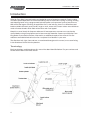
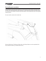
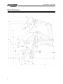
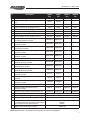
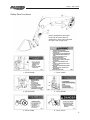
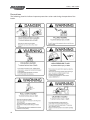
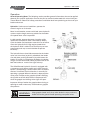
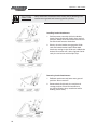
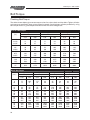
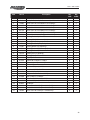
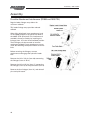
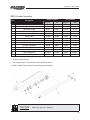
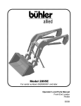
Operator and Parts Manual
2895 Loader
For serial numbers 0528950045 and later
122011
P4110
Table of Contents - 2895 Loader
Table of Contents
Introduction..................................................................................................................................4
Serial Decal Location....................................................................................................................5
Specifications................................................................................................................................6
Safety.............................................................................................................................................8
• Safety.................................................................................................................................8
• General Safety...................................................................................................................9
• Safety Signs....................................................................................................................10
• Safety Sign Installation..................................................................................................10
• Safety Decal location...................................................................................................... 11
• Precautions......................................................................................................................12
Operation....................................................................................................................................13
• Pre-Operation..................................................................................................................13
• Operation.........................................................................................................................14
Maintenance...............................................................................................................................25
• Lubrication.......................................................................................................................25
TSL General Note and Instructions...........................................................................................30
Troubleshooting..........................................................................................................................32
Bolt Torque..................................................................................................................................34
• Checking Bolt Torque......................................................................................................34
Parts.............................................................................................................................................36
• Main Frame Assembly Drawing and Parts List.............................................................36
• Hydraulic Plumbing Assembly and Parts List...............................................................38
• Main Frame Assembly - TSL Drawing and Parts List...................................................40
• Hydraulic Plumbing Assembly - TSL and Parts List......................................................42
Assembly.....................................................................................................................................44
• Possible Attachment Interference (TSL)........................................................................44
• Cylinder Assembly..........................................................................................................45
Warranty......................................................................................................................................46
Manufacturer’s statement: for technical reasons Buhler Industries Inc. reserves the right to modify
machinery design and specifications provided herein without any preliminary notice.
Information provided herein is of descriptive nature. Performance quality may depend on soil fertility,
applied agricultural techniques, weather conditions and other factors.
3
Introduction - 2895 Loader
Introduction
Allied by Farm King front-end loaders are backed by years of extensive research. Factory testing
simulates specific operations to evaluate durability; days of continuous cycling in raising, twisting
and dropping loads using a programmed hydraulic power unit represents years of extreme use.
With one of the largest mounting kit application lists in the industry, there is an Allied front-end
loader available for nearly every tractor, large or small, new or old. Custom colors are available to
match all tractor brands which adds resale value and visual appeal.
Keep this manual handy for frequent reference. All new operators or owners must review the
manual before using the equipment and at least annually thereafter. Contact your Allied by Farm
King Dealer if you need assistance, information, or additional copies of the manual. Visit our
website at www.buhlerindustries.com for a complete list of dealers in your area.
The directions left, right, front and rear, as mentioned throughout this manual, are as seen facing
in the direction of travel of the implement.
Terminology
Basic terminology used throughout this manual has been identified below. For part numbers and
further details refer to the Parts section.
4
Serial Decal Location - 2895 Loader
Serial Decal Location
The serial decal is located on the inside left arm of the loader joint plate. Please record the serial
number in the space provided for future reference. The serial decal will provide the model and date
of manufacture of the loader and will be required to obtain correct replacement parts and complete
warranty claims.
For your records, record serial number here:
Warranty Registration: The Warranty Registration and Delivery Report must be completed within
thirty (30) days of delivery to validate the warranty.
5
Specifications - 2895 Loader
Specifications
6
Specifications - 2895 Loader
It.
Description
2895E
Reg
181/460
2895E
TSL
181/460
2895E S
Reg
169/429
160/406
2895E S
TSL
169/429
160/406
A
Maximum lift height to pivot pin [in/cm]
B
Maximum lift height under level bucket [in/
cm]
172/437
172/437
C
Clearance with bucket dumped [in/cm]
146/370
146/370
134/340
134/340
D
Reach at maximum lift height [in/cm]
29/74
29/74
20/51
20/51
E
Maximum dump angle [deg]
62
61
62
61
G
Maximum rollback angle [deg]
37
37
37
37
H
Digging depth [in/cm]
5.0/12.7
5.0/12.7
5.0/12.7
5.0/12.7
J
Overall height in carry position [in/cm]
101/255
103/262
U
Lift capacity to maximum height - at pivot
pin [lb/kg] optional cylinder
7000/3175
6900/3129
V
Lift capacity to maximum height [lb/kg]
optional cylinder
4950/2245
4950/2245
W
Lift capacity to 59 in. height - at pivot pin [lb/
kg] optional cylinder
7650/3470
7650/3470
X
Lift capacity to 59 in. height [lb/kg]
optional cylinder
6125/2778
6125/2778
Y
Breakout force - at pivot pin [lbf/daN]
optional cylinder
8475/3770
8500/3781
Z
Breakout force [lbf/daN] optional cylinder
6550/2914
6550/2914
VV
Bucket rollback force at maximum height
[lbf/daN] optional cylinder
6250/2780
6375/2836
XX
Bucket rollback force at 59 in. lift height [lbf/
daN] optional cylinder
8000/3559
7850/3492
ZZ
Bucket rollback force at ground line
[lbf/daN] optional cylinder
7400/3292
7025/3125
Raising/Lowering time [sec]
optional cylinder
8.1/5.5
8.1/5.5
Bucket dumping/rollback time [sec]optional
cylinder
4.0/2.6
4.0/2.6
3.50/2.00
3.50/2.00
Lift cylinder tube/shaft size [in]
optional cylinder
Lift cylinder stroke/retracted length [in]
Bucket cylinder tube/shaft size [in]
optional cylinder
Bucket cylinder stroke/retracted length [in]
32.50/52.50
101/255
103/262
6900/3129
6875/3118
4925/2234
4925/2234
8375/3798
8400/3800
6600/2993
6600/2993
9950/4426
9950/4426
7450/3314
7475/3325
6300/2802
6400/2847
8000/3559
7875/3503
7400/3292
7000/3114
8.1/5.5
8.1/5.5
4.0/2.6
4.0/2.6
3.50/2.00
3.50/2.00
32.50/52.50 32.50/45.25 32.50/45.25
3.00/1.75
3.00/1.75
3.00/1.75
27.50/38.75
24.50/52.25
Mounting Height (+/- 3.0) [in]
27.50/38.75 24.50/52.25
55
Hydraulic pressure rating/flow rate [psi]/[gpm]
2500/20
Tractor size [H.P. @ normal duty]
130-275
Bucket size [in/cu.ft.]
- * Indicates bucket size used for calculations
of lift capacities and rollback forces.
72/27.0
84/30.5*
96/37.3
Weight (with bkt & mtg kit) [lb/kg]
3.00/1.75
3800/1270
NOTE: Specifications are subject to change without notice or obligation
7
Safety - 2895 Loader
Safety
Safety Instructions
Remember, YOU are the key to safety. Good safety practices not only protect you, but also the
people around you. Make these practices a working part of your safety program. Be certain that
everyone operating this equipment is familiar with the recommended operating and maintenance
procedures and follows all the safety precautions. Most accidents can be prevented. Do not risk
injury or death by ignoring good safety practices.
The alert symbol is used throughout this manual. It indicates attention is required and identifies
hazards. Follow the recommended precautions.
The safety alert symbol means…
ATTENTION! BECOME ALERT! YOUR SAFETY IS INVOLVED!
8
Caution
The caution symbol indicates a potentially hazardous situation
that, if not avoided, may result in minor or moderate injury. It
may also be used to alert against unsafe practices.
Warning
The Warning Symbol indicates a potentially hazardous situation
that, if not avoided, could result in death or serious injury, and
includes hazards that are exposed when guards are removed. It
may also be used to alert against unsafe practices.
Danger
The Danger Symbol indicates an imminently hazardous situation
that, if not avoided will result in death or serious injury. This
signal word is to be limited to the most extreme situations,
typically for machine components that, for functional purposes,
cannot be guarded.
Safety - 2895 Loader
General Safety Instructions
• Have a first-aid kit available for use and know how to use it.
• Have a fire extinguisher available, stored in a highly visible location, and know how to use it.
• Wear appropriate protective gear. This list may include but is not limited to:
-- hard hat
-- protective shoes with slip resistant soles
-- protective glasses or goggles
-- heavy gloves
-- wet weather gear
-- hearing protection
-- respirator or filter mask
• Read and understand the Operator’s Manual and all safety signs before operating, servicing,
adjusting, repairing, or unplugging the equipment.
• Do not attempt any unauthorized modifications to your Allied by Farm King product as this
could affect function or safety, and could affect the life of the equipment.
• Inspect and clean the working area before operating.
• Keep hands, feet, clothing, and hair away from moving parts.
• Ensure bystanders are clear of the area before operating.
• Improper use of the loader and tractor can cause serious injury or death.
• Operate the loader while seated in the tractor seat only.
• Keep the work area clear of other persons.
• Never leave the tractor unattended while the attachment is raised. Always lower the
attachment to ground and shut tractor off before leaving the tractor seat.
• Never work beneath a raised loader unless it is securely supported. The control lever can be
moved or a hydraulic leak could cause the loader to drop resulting in serious injury or death.
Refer to the Hydraulic Lock Instructions Decal for proper use of the lift locks.
• Prior to use, check to ensure the attachment is properly locked to the quick-tach. Verify from
tractor seat by lowering the attachment to the ground and retracting the lift cylinders.
• Never operate loader with frayed or damaged hoses or leaking fittings. A burst could cause
the loader to drop suddenly and result in serious injury or death and cause damage to the
loader or tractor.
• Keep tractor on solid ground when raising loader. Loose fill rocks and holes can be
dangerous for loader operation and movement.
• If for some reason, you feel the tractor tipping, immediately lower the loader.
• A pivoting front axle acts like a three-wheeled tractor until the stops hit the axle.
• Space rear tires as recommended by the tractor manufacturer. Maximize width for high lift
applications and uneven terrain.
• Add rear ballast as required to ensure 25% of gross vehicle weight is transferred to the rear
axle. Loader, attachment and payload must be included as weight.
• Do not raise attachment to extreme heights while tractor is on an incline. Be alert for terrain
changes and adjust accordingly. Keep attachment at low travel height, no more than one
foot, as long as possible.
• Allow for attachment and loader length when turning.
• The tractor must be equipped with an approved Roll Over Protection Structure (ROPS) and
safety belts.
9
Safety - 2895 Loader
• Use proper lighting and safety warnings when transporting equipment on public roads and
during darkness. The Slow Moving Vehicle (SMV) emblem must be visible. Check with your
local Law Enforcement Agency for specific requirements.
Safety Signs
• The following illustration shows the approximate location and detail of safety signs.
• Keep all safety signs clean and legible and replace any that are damaged or missing.
• When original parts are replaced, any safety signs affixed to those parts should be replaced
as well. Replacement safety signs are available from your local dealer.
Installation
• To install safety signs, ensure the installation area is clean and dry. Decide on the exact
position before you remove the backing paper. Remove the smallest portion of the split
backing paper and align over the specified area. Carefully press in place.
• Slowly peel back the remaining paper and smooth the remaining portion in place. Small air
pockets can be pierced with a pin and smoothed out.
10
Safety - 2895 Loader
Safety Decal Locations
Decals provided for both right
hand and left hand (shown)
applications. Item 4 only required
for right hand upright only.
1 - Part # 813689
1 - Part # 112812
3 - Part # 813439
4 - Part # 813902
5 - Part # 112983
6 - Part # 113711
11
Safety - 2895 Loader
Precautions
The following pictorials indicate important precautions to be used during the operation of the
loader.
12
Operation - 2895 Loader
Operation
Pre-Operation
The following pictorials indicate important precautions to be used during the operation of the
loader.
Warning
The tractor must be equipped with an approved Roll
over Protection Structure (ROPS) and safety belts to help prevent
personal injury or death caused by tractor roll over.
Caution
Maximum rated loader capacity may exceed tractor
rating. Load restrictions or reduction in hydraulic operating
pressure may be required for safe operation. Torque all fittings
and hoses prior to operating loader. Ensure hoses do not rub or
pinch during loader operation. Ty-rap as required.
Rops: Do not exceed the manufacturer’s rating for maximum gross vehicle weight. Refer to the
Tractor Manual or the ROPS Serial Decal for rating. Do not alter or modify the ROPS structure.
Tractor Tires: Space rear tires as recommended by the tractor manufacturer. Tire inflation and
capacity must meet or exceed additional weight of loader, attachment and payload. Maximize
width for high lift applications. Tread width must not exceed maximum width as recommended in
the Mounting Kit Listing.
Warning
Add rear ballast to help prevent personal injury or death
caused by tractor roll over.
Rear Ballast: Rear ballast is required to ensure 25% of gross vehicle weight is transferred to the
rear axle. Attachment and load must be included as weight. Adequate rear weights are required
to counterbalance maximum loader capacity and safe loader operation. Weight can be added as
rear tire liquid (calcium solution), rear wheel weights, rear axle weights and/or three point hitch
mounted ballast or implement. Ballasting will vary with tractor and loader attachment. Refer to
the Tractor Manual for recommended ballasting.
13
Operation - 2895 Loader
Operation
General Operating Notes: The following section provides general information that can be applied
towards your specific application. Ensure that you’ve read and understood this manual and your
Tractor Manual. Observe all safety precautions and follow local laws pertaining to the use of your
loader and tractor.
Hydraulics: Under normal conditions, operate the
tractor’s engine at 1/2 throttle.
Note: In cold weather, tractors with load sense hydraulic
systems require longer warm-up periods for the loader
to respond when valve is operated.
In cold weather, operate the tractor’s engine at idle
speed until the hydraulic fluid is warmed up. Slowly
cycle the loader and attachment several times to further
warm the hydraulic fluid. High engine speed when
the hydraulic fluid is cold will cause the pump to wear
prematurely and may cause the loader to operate
erratically.
The hydraulic hoses should be connected to the loader
valve such that when joystick is pulled back the loader
rise and when pushing forward on joystick lowers the
loader. (If joystick is pushed past the detent, the loader
will go in to the float mode.) Move joystick to left to roll
back the bucket an move to the right to dump.
The Allied Remote Hydraulic Control is equipped with
a momentary push button switch and a lock. The push
button is for operating a third function when an electric
diverter is installed. The third function is normally for
operating a grapple. When the button is depressed the
valve ports are open to the grapple cylinders. Shifting
the joystick to the left while button is depressed will
close the grapple and shifting to the right will open.
Important: Always feather the grapple when closing or
opening to avoid unnecessary shock loads on grapple
components.
Warning
14
Keep grapple closed at all times when bucket is empty and carry
bucket low to the ground. Avoid operating near power wires.
Operation - 2895 Loader
All Allied by Farm King hydraulic valves are self-centering and return to neutral from all positions
except float. The float or detent spool is only to be used on the boom circuit. This position allows
the oil to freely flow through the valve so the lift cylinders can extend or retract. It can be engaged
by slightly pushing control beyond full lower. Float will allow for the loader to lower and rise as
the attachment follows the ground contours. To disengage float, slightly pull control back towards
the neutral position. The Allied by Farm King Remote Hydraulic Control can be locked in the neutral
position to minimize unintentional movement.
Caution
Lower and dump heavy loads slowly by feathering. Stop tractor
movement gradually. Never drop a loaded attachment and
“catch” hydraulically. Stopping with such downward momentum
may cause damage to the loader or tractor.
When handling heavy loads be sure to raise and lower the loader slowly while leveling the
attachment as required. Feathering can assist in accurately controlling operations by regulating oil
flow through cylinders.
A third function hydraulic control is available for grapple or other hydraulic applications. An
optional divertor valve is connected to the loader attachment spool and is operated via the Allied
by Farm King Remote Hydraulic Control momentary switch and simultaneously engaging the
bucket spool through dump or rollback.
Bucket
When loading a bucket, approach straight and
enter the pile with a level bucket parallel to the line
of motion.
Important: Attempting to turn while loading may
cause damage to the loader or tractor.
Work the controls to raise and rollback the bucket
simultaneously. The combined actions of lift and
bucket cylinders increases loading efficiency and
minimizes resistance to lift.
Note: On tractors with low hydraulic oil flows, both
functions may not be possible
15
Operation - 2895 Loader
Minimize turning angle and length of run between
pile and trailer to increase loading efficiency. Also,
place load evenly or centered in the attachment.
Warning
Carry the load no higher than necessary to clear the terrain. Turn
and brake slowly. Always be sure that loading area is level and
on solid ground. Do not raise loader higher then required while
dumping. Immediately lower the loader to ground if the tractor
becomes unstable.
Leave material, which drifts over the bucket sides
for final cleanup.
Backfilling or Scraping
For forward back filling, approach pile with a level
bucket. Utilize the float position to minimize bucket
cutting edge wear. Leave dirt in bucket. Dumping
on each pass reduces efficiency.
Note: Use leveling rod for a guide to ensure bucket
is level.
Do not use bucket in dumped position for forward
grading. This will only impose severe shock loading
on the bucket cylinders and it is difficult to maintain
a level grade.
16
Operation - 2895 Loader
For back grading, either load the bucket and
position the heel on the ground or position the
bucket at 40° or less below level as shown. Place
the valve in the float position and back up slowly.
Important: Float position must be used to reduce
down pressure, otherwise cylinder rod(s) and/or
bucket damage could occur.
A Frame:
Regular Duty / Heavy Duty 60"
Both A-frames are for handling medium to
large sized round bales (up to 2000 lbs) when
fitted with two bottom 1240mm long heat treated
spears and two short stabilizers. For pallet
applications with a maximum payload of 4400 lbs
when fitted with the 48.0” pallet fork kit.
Note: The heavy duty frame can also be fitted using
only the one center spear.
17
Operation - 2895 Loader
Warning
Do not operate A Frame for bales without stabilizers.
Handling bales and pallets:
For safe handling of bales and pallets please follow
procedures below:
With a single spear, enter one of the ends of the
bale and drive the spear horizontally into the
center or slightly above center of the bale and
fully penetrate the bale. Then rollback the bucket
cylinders approximately three quarters of the
cylinder stroke and lift bale approximately a foot
off the ground.
With the double or four spears enter the bale
from one of the ends and drive the spear one
third to one half the way up, from the bottom and
fully penetrate the bale. Then rollback the bucket
cylinders approximately three quarters of the
cylinder’s stroke and lift bale approximately
12.0" off the ground.
Caution
18
Never attempt to use the spears as forks, as the spears can easily
penetrate theground causing a spear to bend or break as well
as making the bale unstable to carry. Never attempt to handle
a bale with only part of the spear(s) penetrated. The nut on the
bale spear must be torqued to 500 ft.-lbs. Check the torque
periodically. A loose spear will damage the spear holder.
Operation - 2895 Loader
When loading bales onto a trailer, park trailer in
close proximity to minimize turning angle and
length of travel to increase loading efficiency.
As you lift the bale using the regular loader, it is
recommended to feather the valve to allow bucket
cylinders to extend to keep bale at about a 20°
angle. (On TSL loaders this is not necessary) Lift
the bale only enough to clear the area that the
bale will be placed on. Always approach the trailer
square to the tractor as shown.
Caution
Avoid sudden stops and sharp turns. Avoid uneven terrain areas
for loading and unloading.
After setting the bale down position the A Frame
with spear(s) horizontal to the ground and slowly
back the tractor straight out.
With pallet forks level and just above the ground,
drive the forks into the pallet completely. Raise
loader to lift pallet and carry level 6 to 12 inches
off the ground. Note: The TSL loader is highly
recommended when operating with pallet forks
for maintaining a constant level load. Use the level
indicator as a guide to ensure forks are level at
ground.
Caution
Avoid sudden stops and sharp turns. Operate at low ground
speeds. Never attempt to lift loads heavier than the rated fork
specs (42" - 2200 lbs) (48" - 4400 lbs). Always lift or carry pallets
using both forks and utilizing the full length of the forks.
Warning
When driving amongst livestock keep bucket cylinders retracted,
and loader boom at least 6 to 7' off the ground. Store A Frame
away from both play and heavy traffic areas.
19
Operation - 2895 Loader
Grapple:
The grapple is designed to safely prevent loads (bales, silage) from falling out of the bucket. (Refer
to pictorial below for options listed)
Warning
20
Travel at low speeds. Carry loads as low as possible. Avoid sharp
turns and uneven terrain.
Operation - 2895 Loader
Caution
Prior to initial mounting, cycle loader cylinders to displace air. This
ensures the loader will remain in the storage position and operate
consistently.
Installing Loader:
1. Position the tractor centrally and parallel to
the loader uprights. Drive forward slowly until
the loader hydraulic hoses can be coupled.
Shut tractor off and set park brake. Couple
the loader hoses to the matched color code
identifiers on the auxiliary valve for proper
orientation of loader operation.
2. Extend lift cylinders to tilt both loader uprights
approximately 30 degrees. Rollback bucket to
further raise upright for additional clearance.
Both upright base pivots must be above the
loader mount cradle.
Caution
Verify front and side clearances during installation to position
hydraulic hoses such that they will not be pinched or stretched
during installation.
3. Slowly drive the tractor forward until the
upright base pivot contacts the mount
plate.
4. Slowly extend the bucket and retract the lift
cylinders to lower the upright pivot into the
mount plate cradle. Ensure both uprights
are fully engaged within the mount plate
cradle.
21
Operation - 2895 Loader
Caution
Shut tractor off and store parking stands within loader cross tube
remembering to stand on the outside of the loader arms. Start
the tractor and continue to cycle loader and attachment to verify
loader operation.
5. With the tractor in neutral, continue to retract
the lift cylinders and extend the bucket
cylinders to rotate the upright back against the
lock pin stops. Shut the tractor off and set park
brake.
6. Install both upright attachment pins and secure
with hairpin clip. Start the tractor and slowly
raise loader until the parking stands are off the
ground.
Caution
Shut tractor off and store parking stands within loader cross tube
remembering to stand on the outside of the loader arms. Start
the tractor and continue to cycle loader and attachment to verify
loader operation.
Removing Loader:
1. Raise loader to provide clearance to engage
both parking stands. Shut off tractor. Standing
along the outside of the loader arms remove
parking stands from storage position and
engage within the loader mainframe.
22
Operation - 2895 Loader
2. Lower attachment level to the ground while
engaging float position. Ensure attachment
rests firmly on ground with minimal downward
pressure. If required extend bucket cylinders
to rotate upright rearward. At this stage the pin
should have no pressure. Set tractor park brake
and remove loader lock pins. Check hydraulic
hoses such that they will not get pinched or
stretched during removal.
Caution
Shut tractor off and store parking stands within loader cross tube
remembering to stand on the outside of the loader arms. Start
the tractor and continue to cycle loader and attachment to verify
loader operation.
3. Retract bucket cylinders to raise upright and
disengage from the loader mount cradle. If
additional clearance is required, extend lift
cylinders while slowly backing the tractor away
from the loader.
4. After the tractor is clear of the loader, retract all
cylinders to protect the shafting. Shut tractor
off and set park brake and relieve oil pressure
in hoses by moving valve control. Disconnect
hydraulic loader hydraulic hoses at the quick
couplers.
Important: Cap both male and female couplers.
Wrap loader hoses over loader arm.
23
Operation - 2895 Loader
Caution
Verify attachment installation from tractor seat by lowering level
attachment to ground and retracting the lift cylinders.
Installing Loader Attachments:
1. Position tractor centrally within the bucket
hooks. Dump Quick-tach slightly from vertical
position. Slowly drive the tractor forward until
the Quick-tach contacts the bucket.
2. Slowly raise the loader to engage the Quicktach within both bucket hooks. When both
hooks are resting on the Quick-tach rollback the
bucket. Shut tractor off. Lock using both Quicktach pins and secure with hairpin clips.
Removing Loader Attachments:
1. Rollback attachment and lower near ground
position. Shut tractor off.
2. Remove both Quick-tach pins and place in
storage position. Place level attachment
on ground. Slowly dump attachment while
backing tractor away.
24
Maintenance - 2895 Loader
Maintenance
Lubrication
Lubricate loader bushings and pivots every eight hours of average operation with high-grade
grease. For grease fitting locations see illustration below. Select grease based on the expected
outside temperature range. Lithium, Molybdenum and synthetic greases are preferred. Use the
tractor hour meter as a guide. Increase lubrication intervals for extreme use or adverse conditions.
Each pivot should be lubricated until grease is visible at pin.
Important: Ensure that grease fittings accept grease. Should any fitting become plugged, replace
immediately. Pivots not greased as specified would cause premature wear of pins and bushings.
25
Maintenance - 2895 Loader
General Inspection:
Caution
Lower attachment and loader to ground, place all controls in
neutral, stop engine, set parking brake and remove ignition key
before inspecting, servicing, adjusting or repairing loader.
Warning
Relieve hydraulic pressure before repairing, adjusting or
disconnecting hydraulics components. Escaping hydraulic oil can
penetrate skin causing serious personal injury. If injured consult a
physician immediately.
Warning
Never work beneath a raised loader unless it is securely
supported. The control lever can be moved or a hydraulic leak
could cause the loader to drop resulting in serious injury or death.
Refer to the hydraulic lift lock instructions decal for proper use of
the lift lock.
Hydraulic Lift Lock: the lift lock on your loader is to be
used whenever someone is attempting to be under the
loader or for tractor servicing. When using the lock ensure
loader is free of any load in the loader attachment or no
attachment.
To engage hydraulic lift lock, raise loader to desired
service height. Rotate lever on hydraulic lock 90° clockwise
to lock. Then lock joystick in neutral position. Do not use if
there are any hydraulic leaks.
Pins and Bushings: Every 6 months or 1000 hours check loader and cylinder pivots for movement
that would be due to bushing or pin wear. Change bushings when excessive movement is noticed
and replace any worn or rough surfaced pins.
26
Maintenance - 2895 Loader
Mounting Kit: After the initial 2 weeks or 40 hours of loader operation, and 6-month intervals
thereafter re-torque all mounting kit bolts. (See Bolt Torque Chart)
27
Maintenance - 2895 Loader
Hydraulics:
Escaping fluid under pressure can have sufficient force to
penetrate the skin, causing serious personal injury. Before
repairing, adjusting, or disconnecting lines, be sure to relieve
all pressure.
Before applying pressure to the system, be sure all
connections are tight and the lines, pipes, and hoses are
not damaged.
Warning
Wear proper hand and eye protection when searching for
leaks. Use a piece of wood or cardboard instead of hand
to check for leaks.
Maintain all components in good working order.
If injured by escaping fluid, see a doctor at once. Serious
infection or toxic reaction can develop if proper medical
treatment is not administered immediately.
With loader attachment on the ground, check and add if necessary the approved hydraulic fluid.
Refer to the Tractor Manual for proper inspection of fluid level, oil type and service intervals.
Visually check hoses and fittings for leaks and damage on a daily bases. Ensure hoses do not bind
or stretch during operation. Always keep hoses tied or supported to prevent rubbing against sharp
areas or being pinched. We suggest using tie wraps to support hoses. Hoses routed from steel lines
to cylinders should be in a relaxed position. To correct, loosen swivel end of hose and retighten.
Warning
Never operate the loader with frayed or damaged hoses or
leaking fittings. A burst would cause the loader to drop suddenly
and result in serious injury or death and cause damage to the
loader or tractor.
Replacement hoses must be equal to a working pressure of 3000 PSI or higher.
A yearly inspection of the valve is
recommended. However the maintenance
intervals on the valve depends on the
surrounding environment or if valve spools
become stiff. Where temperatures fluctuate
from one extreme to another or exposed to
high salt the intervals for maintenance should
be increased to protect from corrosion.
On non-cab tractors mounted with the joystick
valve, slip back the boot and clean away any
debris. Spray a corrosion resistant lubricant
and remount the boot. Replace a torn or
cracked boot.
28
Maintenance - 2895 Loader
Warning
Shut tractor down and relieve oil pressure in system by moving
the control valve spools in both directions before doing any
maintenance.
Maintenance involves yearly removal of valve spool end caps and cleaning all debris and
corrosion. Spray area with a corrosive resistant lubricant and recap.
Caution
Never use grease to lubricate valve components where
climate temperature drops below 0° as this could cause spools to
jam.
On valves fitted with joystick cables loosen off jam nut and cable sleeves to gain access to the
valve spool. Clean all debris and any existing corrosion. Spray areas with a light corrosion
resistant lubricant. Re-mount cables sleeves and adjust so that joystick is centered in both axis to
the base. Lock cable sleeve by using the jam nut. Note: In severe cold weather climates, inspect
and maintain the valve and joystick cables before cold weather.
29
Maintenance - 2895 Loader
TSL General Note and Instructions
1. The true self leveling system (TSL) utilizes mechanical linkages to maintain bucket level
while raising and lowering. The pivot plate weldment, leveling tubes and linkages have been
developed to ensure that the bucket remains at the same position throughout its range of
motion. This feature is standard with 2.50" and 3.00" diameter bucket cylinders.
2. The TSL system incorporates a relief and anticavitation manifold to provide extra dump at
ground and rollback at full lift height. This feature is available on 3.00" bucket cylinders only.
If the loader is raised with the bucket fully dumped, oil from the bucket piston side will be
bypassed at high pressure to the bucket shaft side and the lift shaft side as the quickattach
contacts the dump stop. If the loader is lowered with the bucket fully rolled back, oil from
the bucket shaft side will be bypassed at high pressure to the bucket piston side and the lift
piston side will provide makeup as the quick attach contact the rollback stop. Note that these
two conditions are likely to occur intermittently and although the pump will be forced to
supply oil at a higher pressure, no damage to the loader components will occur. It is, however,
recommended to avoid the above situations and keep the bucket somewhat level while raising
or lowering the loader for smoother operation.
3. The extra bucket stroke length allows for the bucket to be dumped to approximately 90° at
ground. This allows for bucket assist when traction is minimal. If the loader is raised from this
position, the bucket will retract as the quick attach contacts the dump stop and the circuit goes
through relief as described in note 2.
4. Extra bucket retraction allows for the bucket to be rolled back as the loader raises. The TSL
feature maintains the bucket level, but as required the bucket can be manually rolled back
approximately 20° to allow for increased bucket capacity. If the loader is lowered from this
position, the bucket will extend as the quick attach contacts the rollback stop and the circuit
goes through relief as described in note 2.
5. The relief valve is factory set at 3250 PSI cracking pressure and is capable of bypassing 10-15
GPM. If loader lock-up should occur due to a low tractor relief setting, higher inlet flows or
return line restrictions, the relief valve may be backed off slightly until the lock-up condition is
overcome (counterclockwise turn of set-screw). Contact the factory for further instructions.
30
Troubleshooting - 2895 Loader
Troubleshooting
Problem
Loader slow and/or will
not dump
Loader chatters or vibrates
when raising and lowering
Excessive movement at
pivots
Possible Cause
Quick couplers leaking
Hydraulic oil too heavy
Change or replace filter
Oil filter plugged
Clean or replace filter
Hydraulic pump worn
Repair or replace pump
Oil line restricted or leaking
32
Replace damaged or restricted
hoses or tube lines
Inspect, clean, repair or replace
valve
Air in hydraulic system
Cycle lift cylinders and bucket
cylinders several times to free
system of air
Cylinder leaks internally
Replace seals
Faulty valve
Repair or replace valve
Air leak in pump inlet line
Check, tighten or replace inlet
line
Air in hydraulic system
Cycle lift cylinders and bucket
cylinders
Oil level too low
Add oil as required
Worn bushings and/or pins
Replace bushings and/or pins
Pump noisy
Oil Leaks at valve
Check all hoses and tubes for
leaks, damage or restrictions
Control valve does not shift
properly
Inlet line restricted or leaking
Oil leaks
Remedy
Check connections and
compatibility or replace
Check for air leaks, restrictions
or collapsed hose
Tighten or replace hose
Clean filter if necessary
Oil level too low
Add oil as required
Pump worn or damaged
Repair or replace pump
Damaged fitting or hoses
Replace damaged parts
Loose connections
Tighten fittings
Worn or damaged o-ring wiper
Install a seal repair kit
seal in cylinder rod end
Worn or damaged o-rings
at valve
Install an o-ring repair kit
Solenoid or o-rings blown at
cap or spool ends (restriction
on return port or pressure
plumbed to return port of
valve)
Remove restriction or ensure
valve is plumbed correctly
Troubleshooting - 2895 Loader
Problem
Insufficient lift capacity
Possible Cause
Remedy
Improper hydraulic pump
operation
Repair or replace pump
Load is greater than boom
lift capacity
Check loader specifications
Internal boom cylinder
leakage
Replace any worn parts and
install a seal repair kit
Improper hydraulic valve
operation
Repair or replace valve
Worn control valve
Worn cylinder piston seals
Have authorized dealer
replace seals
Excessive wear on bottom of
bucket and wear pads
Float position not used while
operating loader
Use float position provided on
valve
Hydraulic cylinders inoperative
Hose from control valve
improperly connected
Refer to plumbing diagrams
Tractor control valve relief
stuck open
See your service manual for
proper adjustment
Incorrect Auxiliary Valve
Check with loader dealer for
proper valve application
Hydraulic control valve set to
low
Adjust valve in accordance
with manual
Slow leak down
Pump operating continually
on closed center tractor
hydraulics system
Loader lift and bucket tilt
controls do not work according Hoses improperly connected
to decal
Refer to plumbing diagrams
and correct hose connections
Open center control valve on
closed center tractor
Replace relief valve with
closed center plug and plug
the power beyond adapter on
valve
Valve noisy and/or hot
Install open center plug on
optional valve
Tractor loads/pump squeals
Stiff control valve
Closed center control valve
on open center tractor
Replaceclosed center plug
with relief and install short
plug in place of the power
beyond adapter
Dirt or moisture build up on
spool ends
Clean spool ends and if
applicable cable ends at valve
Incorrect torque (applies to
sectional valves only)
Loosen and re-torque bolts to
specs
33
Bolt Torque - 2895 Loader
Bolt Torque
Checking Bolt Torque
The tables shown below give correct torque values for various bolts and hex bolts. Tighten all bolts
to the torques specified in chart unless otherwise noted. Check tightness of bolts periodically, using
bolt torque chart as a guide. Replace hardware with the same strength bolt.
Standard Bolt Torque
Bolt Size
(in)
Grade 2
Grade 5
Grade 8
Torque
Torque
Torque
ft-lb
NM
ft-lb
NM
ft-lb
NM
0.25
0.313
0.375
6
11
20
7
15
27
8
17
31
11
23
41
12
25
44
16
33
60
0.438
0.5
0.563
32
49
70
43
66
95
49
76
109
66
103
148
70
106
153
95
144
207
0.625
0.75
0.875
97
144
166
131
195
225
150
266
430
203
360
583
212
376
606
287
509
821
1
1.125
1.25
250
354
500
339
480
678
644
795
1120
873
1077
1518
909
1288
1817
1232
1745
2462
1.375
1.5
655
870
887
1179
1470
1950
1992
2642
2382
3161
3228
4283
Metric Bolt Torque
Bolt Size
(mm)
34
Class 5.6
Grade 8.8
Grade 10.9
Grade 12.9
Torque
Torque
Torque
Torque
ft-lb
NM
ft-lb
NM
ft-lb
NM
ft-lb
NM
6
8
10
3.1
7.7
15
4.3
10.5
21
7.3
17.7
35
9.9
24
48
10.3
25
49
14
34
67
12.1
29
59
16.5
40
81
12
14
16
26
42
64
36
58
88
61
97
147
83
132
200
86.2
136
210
117
185
285
103
162
250
140
220
340
18
20
22
89
126
169
121
171
230
202
287
390
275
390
530
287
405
549
390
550
745
346
486
656
470
660
890
24
27
30
217
320
435
295
435
590
497
733
995
675
995
1350
708
1032
1401
960
1400
1900
840
1239
1681
1140
1680
2280
33
36
39
590
759
988
800
1030
1340
1349
1740
2249
1830
2360
3050
1902
2441
3163
2580
3310
4290
2278
2935
3798
3090
3980
5150
Bolt Torque - 2895 Loader
Hydraulic Fitting Torques
Dash Size
Thread
Size
Jam Nut or Straight
SAE 37° (JIC)
ORB Fitting Torque
Swivel Nut Torque
ft-lb
NM
ft-lb
NM
-04
-05
-06
7/16-20
1/2-20
9/16-18
14-16
18-20
24-26
20-22
24-27
33-35
10-11
13-15
17-19
13-15
18-20
23-26
-08
-10
-12
3/4-16
7/8-14
1-1/16-12
50-60
72-80
125-135
68-78
98-110
170-183
34-38
50-56
70-78
47-52
69-76
96-106
-14
-16
-20
1-3/16-12
1-5/16-12
1-5/8-12
160-180
200-220
210-280
215-245
270-300
285-380
80-90
94-104
124-138
110-122
127-141
169-188
-24
1-7/8-12
270-360
370-490
156-173
212-235
Prevailing Torque Locknuts
Nut Size
and Threads
Grade B Nuts
Grade C Nuts
Nut Tightening Torque
Nut Tightening Torque
ft-lb
NM
ft-lb
NM
Coarse Thread
0.250-20
0.313-18
0.375-16
5-7
9-12.5
14.5-20
7-9
12-17
20-27
7-10
11-16
20-28
9-14
15-22
27-38
0.438-14
0.500-13
0.563-12
23-32
37-50
50-70
31-43
50-68
68-95
31-43
45-62.5
70-95
42-58
61-85
95-129
0.625-11
0.750-10
0.875-9
70-95
125-165
185-250
95-129
169-224
251-339
90-122.5
155-210
225-312.5
122-166
210-285
305-423
1.000-8
275-375
373-508
360-462.5
360-462.5
Fine Thread
0.250-28
0.313-24
0.375-24
5.5-7.5
10-13
16-22
7-10
14-18
22-30
7-10
12-17
21-29
9-14
16-23
28-39
0.438-20
0.500-20
0.563-18
24-34
37.5-52.5
57.5-77.5
33-46
51-71
78-105
31-43
50-70
70-95
42-58
68-95
95-129
0.625-18
0.750-16
0.875-14
72.5-97.5
120-165
200-270
98-132
163-224
271-366
90-125
155-210
225-312.5
122-169
210-285
305-423
1.000-14
300-400
407-542
362.5-500
491-678
For Grade A locknut torque specifications refer to Grade B specifications
35
Parts - 2895 Loader
Main Frame Assembly
36
Parts - 2895 Loader
Item
1
Part #
Description
Qty
2895
Qty
2895S
24966
2895 Main Frame Weldment (113579, 113633 included)
24944
2895 S Main Frame Weldment (bushings included)
1
2
25165
2895 Quick Attach Weldment
1
1
3
Ref.
Lift Cylinder (see cylinder assembly)
2
2
4
Ref.
Bucket Cylinder (see cylinder assembly)
2
2
5
115585
Pin Weldment (quick attach)
2
2
6
24940
Upright Weldment Right
1
1
7
24939
Upright Weldment Left
1
1
8
115527
Pin Weldment (upright)
2
2
9
116344
Link Weldment 17.0"
4
4
10
116343
Link Assembly 10.50"
4
4
1
11
116349
Link Spacer
2
2
12
115486
Stand Tube
2
2
13
114303
Stand Foot
2
2
14
115906
Pin 1.25 Dia x 6.75
2
2
15
115904
Pin 1.25 Dia x 6.25
4
4
16
115900
Pin 1.25 Dia x 5.25
4
4
17
115908
Pin 1.50 Dia x 6.75
2
2
18
113579
Bushing 1.50 Id x 1.88 Od
4
4
19
113633
Bushing 1.25 Id x 1.63 Od
8
8
20
113691
Bushing 1.25 Id x 1.63 Od x 0.75 Lg
8
8
21
12779
Hair Pin Clip
6
6
22
110907
Stand Pin
2
2
23
81669
Hex Bolt 0.625 Unc x 3.5 Lg
2
2
24
81967
Nut Lock 0.625 Dia
6
6
25
81344
Nut Lock (Nylon) 0.375 Unc
7
9
26
81570
Flat Washer 0.375 Dia
4
4
27
24242
Cross Tube Cover
1
1
28
81592
Nut Hex 0.375 Unc Gr2 Pl
4
4
29
81637
Lock Washer 0.50 Dia
2
2
30
813228
Wing Nut 0.50 Dia
2
2
31
115909
Pin Cap
11
11
32
81615
Washer Lock 0.438 Dia
15
15
33
81597
Hex Bolt 0.438 Unc x 1.00 Lg Gr5 Pl
16
16
34
115564
Leveling Rod
16
16
35
115813
Leveling Rod Guide
1
1
36
116347
Pin 1.25 Dia x 7.25
4
4
37
Parts - 2895 Loader
Hydraulic Plumbing Assembly
38
Parts - 2895 Loader
Item
Part #
1
Ref.
2
Ref.
3
Description
Qty
2895
Qty
2895S
Bucket Cylinder (cylinder assembly for breakdown)
2
2
Lift Cylinder (cylinder assembly for breakdown)
2
2
812703
Hose 3/8 x 22 3/4-16 Morb x 3/4-16 Swfjic
4
4
4
114492
Hose 3/8 x 22 3/4-16 Swfjic x 3/4-16 Swfjic
2
4
812696
Hose 3/8 x 18 3/4-16 Swfjic x 3/4-16 Swfjic
5
114605
Hose 3/8 x 24 3/4-16 Morb x 3/4-16 Swfjic
5
811754
Hose 3/8 x 18 3/4-16 Morb x 3/4-16 Swfjic
6
112837
Tubing Bucket Cyl Cross Tube
2
7
112937
Tubing Lift Cyl Common (31.0)
2
7
113031
Tubing Lift Cyl Common (23.0)
8
115510
Tubing Bucket Cyl Top/Dump
8
115701
Tubing Bucket Cyl Top/Dump
9
115511
Tubing Bucket Cyl Bottom/Rollback
9
115702
Tubing Bucket Cyl Bottom/Rollback
10
115512
Tubing Lift Cyl Top/Drop
1
1
11
115513
Tubing Lift Cyl Bottom/Raise
1
1
2
2
2
2
2
1
1
1
1
12
11362
Clip Pipe Std
9
9
13
811414
Elbow 90 3/4 Morb x 3/4 Mjic
2
2
14
812128
Elbow 90 3/4 Mjic x 3/4 Mjic
4
4
15
812069
Tee 3/4 Mjic
4
4
16
81344
Nut Lock (Nylon) 0.375 Nc
9
9
17
81592
Nut Hex 0.375 Nc Gr2 Pl
4
4
39
Parts - 2895 Loader
Main Frame Assembly - TSL
40
Parts - 2895 Loader
Item
Part #
Description
1
2
3
4
5
6
7
8
9
10
10
11
12
13
14
15
16
17
18
19
20
21
22
23
24
25
26
27
28
29
30
31
32
33
34
35
36
37
38
39
24967
24945
25165
Ref.
Ref.
115585
24942
24941
115527
115473
115583
115475
116344
116343
116349
115486
114303
115906
115804
115900
115908
113579
113633
113691
12779
110907
81669
81967
81344
81570
24242
81592
81637
813228
115909
81615
81597
115564
81966
114969
115012
2895 Tsl Main Frame Weldment (bushings incl.)
2895 S Tsl Main Frame Weldment (bushings incl.)
2895 Quick Attach Weldment
Lift Cylinder (see cylinder assembly)
Bucket Cylinder (see cylinder assembly)
Pin Weldment (quick attach)
Upright Weldment Right (Tsl)
Upright Weldment Left (Tsl)
Pin Weldment (Upright)
Pivot Plate
Leveling Tube Weldment
Leveling Tube Weldment
Link Weldment 17.0"
Link Assembly 10.50"
Link Spacer 2.0 Od x 2.5 Lg
Stand Tube
Stand Foot
Pin 1.25 x 6.75
Pin 1.25 x 6.25
Pin 1.25 x 5.25
Pin 1.50 x 6.75
Bushing 1.50 Id x 1.88 Od
Bushing 1.25 Id x 1.63 Od
Bushing 1.25 Id x 1.63 Od x 0.75 Lg
Hair Pin Clip
Stand Pin
Hex Bolt 0.625 Unc x 3.5 Lg
Nut Lock 0.625 Unc
Nut Lock (Nylon) 0.375 Unc
Flat Washer 0.375 Dia
Cross Tube Cover
Nut Hex 0.375 Unc Gr2 Pl
Lock Washer 0.50 Dia
Wing Nut 0.50 Dia
Pin Cap
Washer Lock 0.438 Dia
Hex Bolt 0.438 Unc x 1.00 Lg Gr5 Pl
Leveling Rod
Nut Lock (Nylon) 0.50 Unc
Guide Bracket
U-Bolt
40
116347
Pin 1.25 x 7.25
Qty
2895
1
1
2
2
2
1
1
2
2
2
Qty
2895S
1
1
2
2
2
1
1
2
2
4
4
2
2
2
10
4
2
2
4
20
8
6
2
2
6
9
4
1
4
2
2
22
22
22
1
2
1
1
2
4
4
2
2
2
10
4
2
2
4
20
8
6
2
2
6
9
4
1
4
2
2
22
22
22
1
2
1
1
4
4
41
Parts - 2895 Loader
Hydraulic Plumbing Assembly - TSL
42
Parts - 2895 Loader
Item
Part #
1
Ref.
2
Ref.
3
Description
Qty
2895
Qty
2895S
Bucket Cylinder (see cylinder assembly for breakdown)
2
2
Lift Cylinder (see cylinder assembly for breakdown)
2
2
114605
Hose 3/8 x 24 3/4-16 Morb x 3/4-16 Swfjic
2
2
4
811467
Hose 3/8 x 36 3/4-16 Morb x 3/4-16 Swfjic
2
2
5
812703
Hose 3/8 x 22 3/4-16 Morb x 3/4-16 Swfjic
2
5
811754
Hose 3/8 x 18 3/4-16 Morb x 3/4-16 Swfjic
6
114492
Hose 3/8 x 22 3/4-16 Swfjic x 3/4-16 Swfjic
6
812696
Hose 3/8 x 18 3/4-16 Swfjic x 3/4-16 Swfjic
7
112837
Tubing Bucket Cyl Cross Tube
2
8
112937
Tubing Lift Cyl Common (31.0)
2
8
113031
Tubing Lift Cyl Common (23.0)
9
115510
Tubing Bucket Cyl Top/Dump
9
115701
Tubing Bucket Cyl Top/Dump
10
115511
Tubing Bucket Cyl Bottom/Rollback
10
115702
Tubing Bucket Cyl Bottom/Rollback
11
115512
Tubing Lift Cyl.Top/Drop
1
2
2
2
2
2
1
1
1
1
1
12
115513
Tubing Lift Cyl Bottom/Raise
1
1
13
11362
Clip Pipe Std.
9
9
14
811414
Elbow 90 3/4 Morb x 3/4 Mjic
2
2
15
812128
Elbow 90 3/4 Mjic x 3/4 Mjic
2
2
16
812069
Tee 3/4 Mjic
6
6
17
81344
Nut Lock (Nylon) 0.375 Nc
9
9
18
81592
Nut Hex 0.375 Nc Gr2 Pl
4
4
19
25253
Hydraulic Manifold
1
1
20
886897
Adaptor Str 7/8 Morb x 3/4 Mjic
4
4
21
812786
Tee 3/4 Mjic x 3/4 Swfjic
2
2
22
812052
Bolt Hex 0.250Nc x 3.00 Gr5 Pl
2
2
23
81922
Nut Lock (Nylon) 0.250Nc x Grbpl
2
2
24
812075
Ty-Wraps
3
3
25
116940
Hose 3/8 x 44 3/4 Swfjic x 3/4-90 Swfjic
1
1
26
116941
Hose 3/8 x 36 3/4 Swfjic x 3/4-90 Swfjic
1
1
27
116942
Hose 3/8 x 20 3/4 Swfjic x 3/4-90 Swfjic
2
2
43
Assembly - 2895 Loader
Assembly
Possible Attachment Interference (S2895 and 2895 TSL)
Regular loader linkage setup allows for
maximum rollback.
TSL loader linkage setup provides reduced
rollback.
When fully rolled back, large attachments (such
as the C2000 Grapple) may contact the 2895 or
the 2895E S TSL pivot plate. This interference is
avoided in factory assembly by installing the
linkages (item 12) in the limited rollback position.
These linkages can be reversed to increase
attachment rollback if large attachments are not
used. See following description below to reverse
links.
Before reversing the linkages, remove
attachments and engage the hydraulic loader
lock.
Remove the 1.25 x 7.25 pin (item 40) connecting
the linkages (items 11 & 12).
Remove the 1.25 x 6.25 pin (item 17) connecting
the linkages (item 12) to the quick attach (item 2).
Reverse the four linkages (item 12), and reinstall
pins and quick attach.
44
Assembly - 2895 Loader
2895 Cylinder Assembly
Item
Description
Bucket Cylinders
Regular
TSL
Lift Cylinders
Regular
Short
Diameter
3.00"
3.00"
3.50"
3.50"
Length of Stroke
27.50"
24.50"
32.50"
32.50"
Retracted Length
38.75"
52.25"
52.50"
45.25"
Extended Length
66.25"
76.75"
85.00"
77.75"
Cylinder Assembly No.
25166
25186
24607
24774
Seal Kit No.
X1424
X1424
X1425
X1425
Shaft Diameter
1.75"
1.75"
2.00"
2.00"
1
Head Plate
24606
24606
24430
24430
2
Shaft Weldment
116264
116368
113700
114719
3
Cylinder Tube Weld't
24949
24951
24785
24785
4
Piston Half (wide)
112862
112862
112940
112940
5
Piston Half (narrow)
112863
112863
112941
112941
6
Self-Locking Nut
813407
813407
810457
810457
7
Shaft Bushing
116342
116342
113633
113633
1. Bucket cylinder shown.
2. All cylinder seals are contained in corresponding seal kit.
3. Refer to Bolt Torque section for prevailing torque locknuts.
caution
Maximum pressure - 3000 psi
45
Warranty - 2895 Loader
Allied by Farm King Limited Warranty
This document limits your warranty rights.
Base Limited Warranty
Buhler Industries Inc. provides this warranty only to original retail purchasers of its product.
Buhler Industries Inc. warrants to such purchasers that all Buhler Industries Inc. manufactured
parts and components used and serviced as provided for in the Operator’s Manual shall be free
from defects in materials and workmanship for a period following delivery to the original retail
purchaser of 12 months (80 days for commercial applications). This limited warranty applies only
to those parts and components manufactured by Buhler Industries Inc. Parts and components
manufactured by others are subject to their manufacturer’s warranties, if any.
Buhler Industries Inc. will fulfill this limited warranty by, at its option, repairing or replacing
any covered part that is defective or is the result of improper workmanship, provided that the
part is returned to Buhler Industries Inc. within thirty (30) days of the date that such defect or
improper workmanship is, or should have been, discovered. Buhler Industries Inc. reserves the
right to either inspect the product at the buyer’s location or have it returned to the factory for
inspection. Parts must be returned through the selling representative and the buyer must prepay
transportation charges.
Buhler Industries Inc. will not be responsible for repairs or replacements that are necessitated,
in whole or part, by the use of parts not manufactured by or obtained from Buhler Industries Inc.
Under no circumstances are component parts warranted against normal wear and tear. There
is no warranty on product pump seals, product pump bearings, rubber product hoses, pressure
gauges, or other components that require replacement as part of normal maintenance. Also:
Buckets and Bucket Tines carry no warranty, Bent Spears carry no warranty, Snowblower Fan
Shafts carry no warranty, Mower Blades carry no warranty, Portable Auger Parts Have Two (2)
Year Warranty, Loader Parts Have Two (2) Year Warranty. The purchaser is solely responsible for
determining suitability of goods sold. This warranty is expressly in lieu of all other warranties
expressed or implied. Buhler Industries Inc. will in no event be liable for any incidental or
consequential damages whatsoever. Nor for any sum in excess of the price received for the
goods for which liability is claimed.
Repair Parts Limited Warranty
Buhler Industries Inc. warrants Allied by Farm King replacement parts purchased after the
expiration of the Buhler Industries Inc. Limited Warranty, and used and serviced as provided for
in the Operator’s Manual, to be free from defects in materials or workmanship for a period of
thirty (30) days from the invoice date for the parts. Buhler Industries Inc. will fulfill this limited
warranty by, at its option, repairing or replacing any covered part that is defective or is the result
of improper workmanship, provided that the part is returned to Buhler Industries Inc. within
thirty (30) days of the date that such defect or improper workmanship is, or should have been,
discovered. Such parts must be shipped to Buhler Industries Inc. at the purchaser’s expense.
What is Not Covered
Under no circumstances does this limited warranty cover any components or parts that have
been subject to the following: negligence; alteration or modification not approved by Buhler
Industries Inc.; misuse; improper storage; lack of reasonable and proper maintenance, service,
or repair; normal wear; damage from failure to follow operating instructions; accident; and/
or repairs that have been made with parts other than those manufactured, supplied, and or
authorized by Buhler Industries Inc.
46
Warranty - 2895 Loader
Authorized Dealer and Labor Costs
Repairs eligible for labor under this limited warranty must be made by Buhler Industries Inc. or
an authorized Allied by Farm King dealer. Buhler Industries Inc. retains the exclusive discretion to
determine whether it will pay labor costs for warranty repairs or replacements, and the amount of
such costs that it will pay and the time in which the repairs will be made. If Buhler Industries Inc.
determines that it will pay labor costs for warranty work, it will do so by issuing a credit to the
dealer’s or distributor’s account. Buhler Industries Inc. will not approve or pay invoices sent for
repairs that Buhler Industries Inc. has not previously approved. Warranty service does not extend
the original term of this limited warranty.
Warranty Requirements
To be covered by warranty, each Allied by Farm King new product must be registered with
Buhler Industries Inc. within thirty (30) days of delivery to original retail purchaser. If the
customer decides to purchase replacement components before the warranty disposition of such
components is determined, Buhler Industries Inc. will bill the customer for such components and
then credit the replacement invoice for those components later determined to be covered by this
limited warranty. Any such replacement components that are determined not be covered by this
limited warranty will be subject to the terms of the invoice and shall be paid for by the purchaser.
Warranty Claims:
Warranty requests must be prepared on Buhler Industries Inc. Warranty Claim Forms with all
requested information properly completed. Warranty Claims must be submitted within a thirty
(30) day period from date of failure repair.
Warranty Labor:
Any labor subject to warranty must be authorized by Buhler Industries Inc. The labor rate for
replacing defective parts, where applicable, will be credited at 100% of the dealer’s posted shop
rate.
Exclusive Effect of Warranty and Limitation of Liability
TO THE EXTENT PERMITTED BY LAW, Buhler Industries Inc. DISCLAIMS ANY
WARRANTIES, REPRESENTATIONS, OR PROMISES, EXPRESS OR IMPLIED, AS TO THE QUALITY,
PERFORMANCE, OR FREEDOM FROM DEFECT OF THE COMPONENTS AND PARTS COVERED BY
THIS WARRANTY AND NOT SPECIFICALLY PROVIDED FOR HEREIN.
TO THE EXTENT PERMITTED BY LAW, Buhler Industries Inc. DISCLAIMS ANY IMPLIED
WARRANTIES OF MERCHANTABILITY AND FITNESS FOR A PARTICULAR PURPOSE ON ITS
PRODUCTS COVERED HEREIN, AND DISCLAIMS ANY RELIANCE BY THE PURCHASER ON
Buhler Industries Inc.’S SKILL OR JUDGMENT TO SELECT OR FURNISH GOODS FOR ANY
PARTICULAR PURPOSE. THE PURCHASER’S ONLY AND EXCLUSIVE REMEDIES IN CONNECTION
WITH THE BREACH OR PERFORMANCE OF ANY WARRANTY ON ProductS manufactured
by Buhler Industries Inc. ARE THOSE SET FORTH HEREIN. IN NO EVENT SHALL Buhler
Industries Inc. BE LIABLE FOR INCIDENTAL OR CONSEQUENTIAL DAMAGES (INCLUDING,
BY WAY OF EXAMPLE ONLY AND NOT LIMITATION, LOSS OF CROPS, LOSS OF PROFITS OR
REVENUE, OTHER COMMERCIAL LOSSES, INCONVENIENCE, OR COST OF REPLACEMENT
OF RENTAL EQUIPMENT). IN NO EVENT SHALL ALLIED BY FARM KING’S CONTRACT OR
WARRANTY LIABILITY EXCEED THE PURCHASE PRICE OF THE PRODUCT.
47
Warranty - 2895 Loader
(Note that some provinces or states do not allow limitations on how long an implied warranty
lasts or the exclusion or limitation of incidental or consequential damages, so the above
limitations and exclusion may not apply to you.) This warranty gives you specific legal rights and
you may also have other rights, which vary from province to province or state to state.
Buhler Industries Inc. neither assumes nor authorizes any person or entity, including its selling
representatives, to assume any other obligations or liability in connections with the sale of
covered equipment, or to make any other warranties, representations, or promises, express or
implied, as to the quality, performance, or freedom from defect of the components and parts
covered herein. No one is authorized to alter, modify, or enlarge this limited warranty, or its
exclusions, limitations and reservations.
Corrections of defects and improper workmanship in the manner, and for the applicable time
periods, provided for herein shall constitute fulfillment of all responsibilities of Buhler Industries
Inc. to the purchaser, and Buhler Industries Inc. shall not be liable in negligence, contract, or on
any other basis with respect to the subject equipment.
This limited warranty is subject to any existing conditions of supply which may directly affect
Buhler Industries Inc.’s ability to obtain materials or manufacture replacement parts.
Buhler Industries Inc. reserves the right to make improvements in design or changes in
specifications to its products at anytime, without incurring any obligation to owners of units
previously sold.
Government Legislation:
Warranty terms and conditions are subject to provincial or state legislation.
Important Note: This warranty does not apply to rentals.
48
www.farm-king.com
1330 43rd Street NW
Fargo, North Dakota USA 58102
Ph.: 701.282.7014 | Fax: 701.282.5865
E-mail: [email protected]
www.farm-king.com
Equipment shown is subject to change without notice.
©2010 Buhler Trading Inc. Printed in USA. TSX:BUI
a division of Buhler Industries Inc.