1
o
Drive Circuit
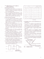
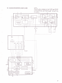
1. The signals employed in the switching of Q2 Q7 in Fig. 7-6 are generated by 3 Hall elements,
and applied to terminals a, b, and c via the
position signal formation circuit.
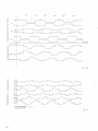
2. "lhe phase of these step waveform signals is
displaced by 120' from each other.
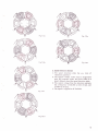
3. When the step waveform signals at position I
in Fig. 7-7a are applied to the drive circuit
terminals a, b, and c, the potential at terminal
a will be lowered, resulting in Q2 being turned
on. The potential at terminal b will be raised,
resulting in Q6 being turned oh, but the
potential at terminal c will remain at the
reference level voltage (the bias settings for
Q4 and Q7 have been designed to prevent
these 2 transistors from operating when a
reference level voltage is applied).
4. Vcc will thus be applied across the Q2 - coil
La - coil Le - (2) - Q6 route, thereby producing an S polarity in La, and an N polarity
in
the magnetic field is generated, the rotor
will commence to rotate. After the rotor turns
5. Once
through 15' , the signals at position II in Fig. 7-7b
will be applied to terminals a, b, and c, thereby
resulting in a change in the flow routes of the
drive currents. After the rotor turns through
another 15', the signals shown at position III
in Fig. 7-?-c will be applied, again resulting in
changes in flow routes of the drive currents.
For every 15' that the rotor turns through, the
flow routes for the drive currents will change
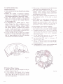
as shown in Figs. 7-7d, 7-7e, and 7-'7f, finally
6.
returning to the routes shown in Fig. 7 -7 a again.
A control voltage generated by the forward/
reverse direction discriminator indicator circuit
is applied to the control input terminal, thereby
controlling the flow of current in the coils.
Ls.
Fis.7-6
1A