1
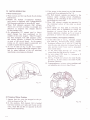
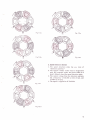
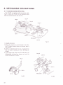
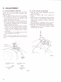
15. When the PU plate completes the lead-in opera-
tion, pin E of the PU plate rotates lever E in
the counter-clockwise direction, resulting in
Iever C separating from the microswitch to
leave the motor power on for continued disc
play (See Fig. 8-7).
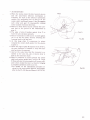
3.
When gear
A
commences
to rotate, plate A
moves towards the tonearm.
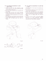
4. Cam C then presses against cam
D attached to
the arm base, resulting in the arm
elevation
being raised.
5. Cam C pushes
pin C of the PU plate across to
the arm rest position. Pin E also moves at
the same time, rotating lever E in the clockwise
direction. Lever E thus pushes lever C to the
right.
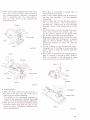
6. Just before plate A reaches the end of its movement across towards the tonearm, pin C of
the PU plate is clasped by the lead-in latch
due to the action of the sub-panel unit hole.
7. When plate A starts to return towards the center
shaft, the lead-in latch holding pin C is opened
again by plate D, thereby releasing pin C to
permit the tonearm to return the arm rest
(fig. 8-13).
8. As cam C returns to the left hand side, cam D
disengages cam C, resulting in the arm elevation
being lowered to drop the tonearm back into
the arm rest.
9. When plate A approaches its original position,
plate C is pushed to the left by cam C fixed to
plate A, resulting in the microswitch being
turned off by lever C to turn the motor off .
PU plate
Pin C
Lead in reach
Cam C
Cam D
Fis. 8-10
Cam B
Pin C
Lead in reach
Plate A
.t 'r
r
Cam C
Fis.8-12
Cam D
Fis. 8-1 1
..
.f
\..\
\..
I
O AUTO-RETURN
1. When the stylus enters the lead-out groove at
the end of the disc, the end of the paly
PU plate C
is
detected by the detector assembly.
Lead in reach
*For details on the operational principles
involved in the auto-return detector mechanism,
refer to the PL-516 Service Manual (ART-279).
2. When the claw of the detector assembly catches
the motor pinion gear (gear B), gear A commences to rotate. Subsequent operation is the
same as during lead-in.
Cam C
Fis. 8-13