1
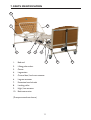
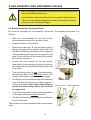
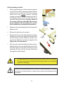
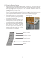
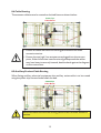
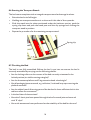
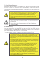
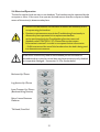
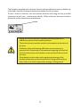
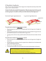
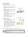
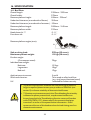
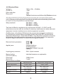
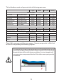
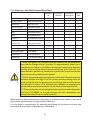
Community Care Bed Range
www.sidhil.com
Instructions for use
Welcome to Sidhil
Still making it better...
At Sidhil, everything we do
is designed around quality.
From our modern and efficient
manufacturing plant in Halifax,
West Yorkshire, we manufacture
a range of products for the
healthcare market using leading
edge production technology and
finishing processes.
We are the only remaining
volume manufacturer of
hospital beds in the UK,
bringing together innovation
in product development,
sales, customer service and
logistics to provide clear
benefits for our customers
in terms of flexibility, short
production timescales and
support from our nationwide
network of service and
maintenance centres.
Excellence in customer
service is our key objective.
Alongside our focus on
innovation, research and
product development, we
use our UK manufacturing
facility to ensure optimum
levels of product and
spares availability,
with unparalleled
levels of reliability and
performance.
Corporate social responsibility
is also an issue for Sidhil. We
have now received accreditation
to ISO 14001, underlining our
commitment to maintaining the
highest levels of environmental
awareness and sustainability
across our manufacturing
operation.
2
CONTENTS
1. INTRODUCTION .............................................................................. 4
2. CONTACT INFORMATION .............................................................. 4
3. PRODUCT DESCRIPTION ............................................................... 5
3.1 Environment .......................................................................................5
3.2 Intended Use ...................................................................................... 5
3.3 Features ..............................................................................................6
4. SAFETY ..............................................................................................7
4.1 Warnings and Cautions ........................................................................ 7
4.2 Risk Assessment ..................................................................................7
4.3 Bed Load ............................................................................................. 7
4.4 General Warnings ................................................................................ 8
5. TRANSPORT AND STORAGE .......................................................... 9
6. SYMBOL DEFINITION ......................................................................10
7. PARTS IDENTIFICATION ................................................................. 11
8. BED ASSEMBLY AND PREPARING FOR USE ...................................12
8.1 Removal from the Transport Stand .......................................................12
8.2 Assembling the Bed ..............................................................................13
8.3 Fitting the Electrical System .................................................................14
8.4 Cable Routing ......................................................................................15
8.5 Ancillary Product Cable Routing .......................................................... 15
8.6 Stowing the Transport Stands ..............................................................16
8.7 Checking the Bed ................................................................................ 16
9. OPERATION OF THE BED ................................................................ 17
9.1 Operational Limits .............................................................................. 17
9.2 Installation / Preparing For Use ............................................................17
9.3 Brake System .......................................................................................19
9.4 Side Rails and Mattresses ..................................................................... 20
9.5 Side Rail Safety ..................................................................................... 20
9.6 Electrical Operation ............................................................................ 21
9.7 Knee Break / Leg Section ..................................................................... 23
9.8 Extending the Bed ............................................................................... 24
10. ASSEMBLY ONTO THE TRANSPORT STAND ...............................25
11. POWER FAILURES ...........................................................................27
12. BATTERY CHARACTERISTICS (SOLITE/UK/4/BB ONLY) ............. 27
13. DECONTAMINATION .....................................................................28
13.1 Cleaning and Disinfection Guidelines ................................................. 28
13.2 Steam Cleaning .................................................................................. 29
14. MAINTENANCE .............................................................................. 30
14.1 General Inspection ............................................................................ 30
14.2 Fault Finding ...................................................................................... 30
14.3 General Maintenance ......................................................................... 31
15. DISPOSAL OF PARTS ...................................................................... 32
16. SPECIFICATION .............................................................................. 33
16.1 Bed Data ............................................................................................ 33
16.2 Electrical Data ....................................................................................34
17. ACCESSORIES ................................................................................. 35
17.1 Mattress / Side Rail Compatibility Chart ............................................. 37
18. WARRANTY .................................................................................... 38
3
1. INTRODUCTION
Thank you for purchasing this product. These instructions for use should be read
carefully before operating the bed. Please ensure that you understand all instructions,
if you have any questions concerning the operation or maintenance of the bed please
contact your provider / supplier who will provide you with expert professional advice.
2. CONTACT INFORMATION
For any service, warranty, sales or customer service information on this product please
contact your provider or if in doubt contact Sidhil Ltd at the following address.
Please quote the Solite UK serial number on all correspondence.
Sidhil Ltd.
Sidhil Business Park
Holmfield
Halifax
West Yorkshire
HX2 9TN
UK
Contact details:
Service & Maintenance
Spares
Customer Service
Tel: +44 (0)1422 233136
Tel: +44 (0)1422 233138
Tel: +44 (0)1422 233000
Fax: +44 (0)1422 233010
Fax: +44 (0)1422 233010
Fax: +44 (0)1422 233010
[email protected]
www.sidhil.com
For Service & Support outside the UK & Northern Ireland please contact the local
distribution company from where this equipment was purchased. Failure to do so may
result in the manufacturer’s warranty becoming void.
4
3. PRODUCT DESCRIPTION
3.1 Environment
Your bed is intended for use in the following environments:
• A medical area where medical supervision is required and monitoring is provided if necessary (e.g. nursing homes, rehabilitation facilities, geriatric facilities etc).
• A domestic area where it is used to alleviate or compensate for an injury, disability or disease.
3.2 Intended Use
The bed has been designed to provide patients with optimum independence and
freedom of movement through the use of a touch button handset.
The bed offers greatly reduced manual handling requirements for the carer by providing
a bed with a fully profiling platform and electrical height adjustment capability.
To aid transportation the bed comes as standard with a transport stand to enable it to
fit through doorways, into lifts, on delivery vehicles etc.
For assistance in setting up, using or maintaining your Solite UK or to report unexpected
operation refer to the contact details found in section 2.
5
3.3 Features
• Electrically operated backrest, height and leg rest angle.
• Infinitely variable electrically operated head* and foot down tilt (Trendelenburg* & reverse Trendelenburg).
• Auto-regressing backrest.
• Integral leg extension.
• Auto contour – simultaneous adjustment of the backrest and leg rest section.
• Patient handset with individual function lockout.
• Bed breaks down into four separate sections.
• Transport stand to aid storage and bed transportation.
• Electrical system IPX4 rated – Splash resistant.
• Battery backup functionality (SOLITE/UK/4/BB only).
Warning
*If patient requirements are such that Trendelenburg functionality is
deemed to pose a potential risk a replacement handset can be purchased
with the Trendelenburg function removed (code CONTROL/127).
Please refer to the contact information in section 2 to order or to request
further information – Sidhil recommend the use of this handset when the
bed is being used in a domestic environment.
6
4. SAFETY
4.1 Warnings and Cautions
Warnings in these instructions for use highlight potential hazards that if
disregarded could lead to injury or death.
Warning
Cautions in these instructions for use highlight potential hazards that if
disregarded could lead to equipment damage or failure.
Caution
4.2 Risk Assessment
Before a patient uses the bed a risk assessment must be performed on a patient by
patient basis. The risk assessment should include, but is not limited to:
• Entrapment.
• Falling out of the bed.
• Children (and small adults).
• Patients with learning difficulties.
• Unauthorised people.
4.3 Bed Load
Safe working load: 222kgs (35 stone)
Maximum patient weight: 191kgs (30 stone)
Safe working load is the sum of:
• Patient mass.
• Mattress mass.
• Accessories mass.
• Mass supported by the accessories (excluding patient mass).
7
4.4 General Warnings
• The bed is to be installed and put into service in accordance with the information provided in these instructions for use.
• The bed is typically not suitable for child use, if it is to be used for child occupancy ensure a risk assessment has been undertaken taking into account the proportions of the child and dimensions of the bed frame.
• The bed is not suitable for occupants who are less than 146cm in length - If in doubt please contact your provider or Sidhil Ltd. for further advice.
• Misused electrical equipment can be hazardous.
• Accessories that have not been approved or designed for use with the bed are not be used.
• Modification of the bed frame is not allowed without the permission of Sidhil Ltd. – A hazard could be introduced.
Warning
• Electrically operated beds shall not be used in the presence of flammable gasses or used in oxygen rich environments – Risk of explosion / fire.
• Bed functions must be locked out if there is any doubt about the ability of the patient to operate the bed safely.
• If children, adults with learning difficulties or even pets pose a potential risk of intentional or unintentional tampering with the bed its suitability for use is to be considered during the initial patient / product risk assessment.
• The maximum loads shown in section 4.3 are for the bed to be occupied by one individual only. The bed is not designed to take the additional weight of individuals sitting on the side of the bed. Additional weight could damage components or cause the bed to become unstable.
• Wireless communications equipment such as wireless home network devices, mobile phones, cordless telephones including their base stations and walkie-talkies could all affect the electrical operation of the bed frame – separation distances must be considered. If the bed or any alternative equipment is found to be
operating abnormally mitigation measures are to be taken, such as
the separation distances being increased and / or the products
being re-orientated.
8
5. TRANSPORT AND STORAGE
The following conditions should be followed when transporting and storing the Solite
UK bed:
• Bed always to be stored on the transport stand.
• Bed ends set to minimum height.
• Bed extension to be compressed.
• Brakes applied.
• All profiling sections secured with hook and loop tape (or similar).
• All functions locked out.
• Covered to protect from fluid ingress, dirt, dust etc. (if required).
• Beds must not be stored one on top of another.
• Beds not to be stored on their side.
• Ambient temperature: -10°C to +50°C.
• Humidity: 20% - 90% at 30°C – not condensing.
• Atmospheric pressure: 800hPa to 1060hPa (altitude ≤ 2000m).
The bed is not intended for patient transport, it is not to be moved out of the room it is located in with a patient occupying the bed, however:
• If the bed is to be pushed up / down a slope it is advised that two people move the bed, with one person at each end.
Warning
• If the bed is to be pushed with a heavy load it should be assessed whether or not two people should move the bed, this is dependent on the situation and load on the bed.
The bed is not to be pushed over thresholds – If done so damage to the
frame could occur.
Caution
9
6. SYMBOL DEFINITION
The following symbols are found on this bed:
Warning
Beware of potential hazard
Refer to instructions for use - Recommended
Failure to read the instructions for use could introduce a hazard
Refer to instructions for use - Mandatory
Failure to read the instructions for use could introduce a hazard
Maximum patient weight
Refer to section 4.3
Safe working load
Refer to section 4.3
Place of manufacture
W.E.E.E Label - Found on individual parts of electrical system
(Waste Electrical and Electronic Equipment) Refer to section 15
Class II electrical device
The user / occupant is protected by at least two layers of insulation between the current
carrying parts (e.g. control box and mains cable) and the metal accessible parts – If damage
is noticed to any electrical component, turn off at the mains and contact your provider or
Sidhil Ltd. immediately.
Type B Applied Part
Applied Part: The parts of the bed that come into physical contact with the user / occupant
in order for the bed to carry out its intended function (refer to section 16.2 for a list of
applied parts).
Type B: Applied parts complying with specific requirements for protection against electric
shock (IEC 60601-1: 2005) and that can be immediately released from the patient.
Mattress suitability
Refer to section 17
Detachable side rail suitability
Use of an incorrectly specified side rail could introduce a hazard
10
7. PARTS IDENTIFICATION
1
10
2
3
4
1.
Bed end
2. Lifting pole socket
5
6
7
3. Castor
4.
Leg section
5.
Control box / back rest actuator
6.
Leg rest actuator
7.
Extension hand wheels
8.
Locking collar
9.
High / low actuator
10. Backrest section
(Transport stand not shown)
11
8
9
8. BED ASSEMBLY AND PREPARING FOR USE
• Before attempting to assemble the bed ensure these instructions have been read and fully understood.
• It is advisable to assemble the bed with a second able bodied person.
Warning
• Take care when disassembling the bed from the transport stand, the sections are of considerable weight.
8.1 Removal from the Transport Stand
No tools are necessary for the assembly of the bed. The assembly procedure is as
follows:
• Clear the area intended for the bed of any
obstructions and ensure the surface is level.
• Apply the brakes to the castors.
• Remove the clevis pin, ‘R’ clip and plastic spacer
that go through each transport stand and hold
the backrest in place (these parts will be required
when assembling the bed sections together) and
then lift this section off the stand and carefully
place it flat on the floor.
• Loosen the hand wheels on the leg section
(attaching it to the transport stand) and then lift
this section off the stand and carefully place it flat
on the floor.
• Turn the locking collars on one of the bed ends so
that they are both in the unlocked position, this
is easily identified by a visible warning triangle.
• Carefully lift the ends of the transport stand away
from the bed end and place carefully against a
wall or on the floor. Note: when the transport
stands are lifted away neither bed end will
be supported.
• Turn the locking collars on the remaining bed end
so that they are in the unlocked position.
• Carefully lift the ends of the transport stand away
from this bed end.
The bed has now been separated into its constituent
parts.
12
Collar locked Collar unlocked
8.2 Assembling the Bed
• Whilst supporting one of the bed ends against
a wall, lift one of the mattress platform halves
and hook into the bed end. Turn the locking
collars into their locked position (warning
triangle not visible). When turning the collar to
the locked position it will rise then fall, this is
the self locking mechanism engaging. Note: If
this action is being undertaken by a single
person Sidhil recommend that the castors
are braked before assembly commences.
• Repeat for the remaining bed end and mattress
platform half.
• Release the brakes on the castors.
• Bring both halves of the bed together and align
each section so that the spigots in the backrest
section locate into the open tube ends in the
leg section. Pull the two sections together and
tighten the 2 hand wheels.
Spigot
• Place the clevis pins through the tube with the
head of the pin on the outside of the bed. Place
the plastic spacer over the end of the pins and
insert the ‘R’ clips in from the top of the bed
through the hole in the pin.
• The bed must never be used with the hand wheels loose or if missing.
Warning
• The bed must never be used with the locking collars in the unlocked
position or if missing.
If the bed has been supplied with tie wraps / hook and loop tape (or similar)
Caution
securing any of the sections in place ensure they are removed prior to
operation.
13
8.3 Fitting the Electrical System
• Plug the actuator and handset cables into the control box. The control box has
a label showing the correct port into which the corresponding cable is inserted.
Note, the plugs only fit into the ports in one orientation. Ensure the cables are
plugged fully into the control box.
Note: The two bed ends are identical however plugging them into the correct
port is important. Note the location of the correct end before plugging in.
• Once all the cables are connected they
are to be secured in place by attaching
the supplied retaining clip.
Mains cable clip
• Clip the mains cable into the hook on the
head end section of the bed (the clip is
secured by twisting the ends together).
• Drive the bed to the maximum height
then secure the actuator cables in
the twist clips. Ensure each bed end
actuator cable has enough flex to allow
full movement of the actuator.
Backrest actuator
Knee break actuator
Foot end actuator
Head end actuator
Handset
14
8.4 Cable Routing
The actuator cables are to be routed on the bed frame as shown below:
Cable Clips
Cable Route
• Ensure all cables are free from moving parts and are not under excessive tension.
Caution
• Ensure the two high / low actuators are plugged into the correct ports, If the tilt function is not functioning as expected the cables may have been incorrectly located, double check against the diagram
on the control box.
8.5 Ancillary Product Cable Routing
When fitting ancillary electrical equipment the ancillary mains cable is to be routed
using the plastic clips located underneath the bed.
Cable Clips
Cable Route
Ensure all cables are free from moving parts and are not under excessive
tension.
Warning
15
8.6 Stowing the Transport Stands
The bed comes complete with an integral transport stand and storage brackets.
• Raise the bed to its full height.
• Holding one transport stand turn it so the words ‘this side in’ face upwards.
• Slide the stand into the tubes positioned under the backrest section, push the
spring clip down and push the stand past until the clip springs back locking the
transport stand in position.
• Repeat the procedure for the remaining transport stand.
Spring clip
8.7 Checking the Bed
The bed is now fully assembled. Before the bed is put into use ensure the bed is
correctly assembled by carrying out the following checks:
• Are the locking collars on the corners of the bed correctly orientated in the locked position (no visible warning triangles)?
• Are the 6 mattress platform and 2 leg extension hand-wheels tight?
• Has all packaging been removed, e.g. cable ties / hook and loop tape securing the platform sections?
• Are the cables free of all moving parts of the bed and is there sufficient slack in the cables to allow for movement?
• Is the bed clear of obstructions? • Have the 2 clevis pins been passed through the bed’s central joint and secured with ‘R’ clips?
• Has a risk assessment been performed on the suitability of the bed for the user?
16
9. OPERATION OF THE BED
9.1 Operational Limits
See section 16.2.
9.2 Installation / Preparing for Use
Prior to operating the bed for the first time the following simple checks must be
performed:
• Ensure the bed and all accessories are at room temperature.
• Ensure the bed has been cleaned and disinfected (see section 13).
• Ensure the brakes on the castors at the head end of the bed have been applied.
• Using the handset ensure the bed is level (see section 9.6 for handset operation).
If the electrical functions do not operate, ensure the handset has been ‘unlocked’ (see
section 9.6 for handset operation).
• The bed is to be left in its lowest position when the patient is unattended in order to reduce the risk of injury due to a fall.
• Before operating the bed ensure the patient is positioned appropriately ensuring all limbs are clear of moving parts.
• The mains plug is the disconnect device for the means of isolating the bed from the mains supply, the plug must be accessible at all times.
• Ensure the mains cable is plugged into an appropriate power source at all times.
• Ensure the electrical cables are not in tension, paying particular attention to the mains cable when the bed travels up/down.
Warning
• Ensure that all cables and the handset are clear of all moving parts to prevent damage to the electrical components.
• Inappropriate handling/positioning of the mains cable could cause kinking or shearing of the cable which may lead to exposed live wires - Risk of electrocution.
• Precautions are to be taken when routing cables from external equipment around the bed to ensure that they do not become squeezed, trapped or damaged.
• A CE marked extension cable must only be used when it is not possible to reach a wall socket with the equipment mains cable – Contact Sidhil Ltd. for detail with regards to the safe use of extension cables.
17
• If an extension cable is used never overload it by plugging in appliances that together will exceed the maximum current rating stated for the extension cable – Risk of fire.
• Block adaptors are not to be used.
• Ensure multiple socket outlets are not positioned under the bed frame - Liquids that leak onto such a socket could pose an electrical / fire risk.
• Any electrical component that is part of the bed frame or associated ancillary equipment that is found to be damaged must be replaced immediately - Damaged electrical components can create a risk of electrocution and / or fire.
• Consideration is to be taken in the positioning of the bed cables and handset cable to minimise the risk of accidental strangulation resulting from baby, child or bed occupant entanglement.
• After assembly of the bed there should be no parts remaining, however consideration is to be taken in the event of spare components (pins, clips etc) being evident to minimise the risk of them being swallowed by a baby, child or the bed occupant and creating a choking hazard.
Warning
• Keep the bed away from sources of heat and naked flames (e.g. cigarettes, fireplaces, electric fires, fan heaters etc) – Close proximity could damage the electrical system, the steel bed frame could become hot, the plastic components could be adversely affected and the bedding could catch fire.
• Avoid placing the bed frame in direct sunlight – Direct sunlight could damage the electrical system, the steel bed frame could become hot, the plastic components could be adversely affected.
• Avoid placing the bed frame in a moisture rich environment – Prolonged exposure to moisture could damage the electrical system, the steel bed frame could be susceptible to corrosion, the plastic components could swell and adversely affect operation.
• Ensure that any mattresses used are of the correct size and type and have been fitted correctly – Incorrect mattress specification could lead to an entrapment and / or falls hazard.
• Ensure the mattress is compatible with the side rails (if fitted).
18
• Special care should be taken when fitting an air mattress to the bed as incorrect fitting could damage the bed frame.
• The bed is not designed to run off battery power for long periods (SOLITE/UK/4/BB only) and should always be plugged into the mains supply during normal use - Allowing the battery to discharge fully may impair its performance.
Caution
• When the bed is operated, ensure that obstacles such as over-bed tables and other furniture are not causing an obstruction.
• Ensure the bed is positioned an appropriate distance from walls / other furniture to prevent damage or patient injury when operating the bed (particularly when operating it in tilt).
9.3 Brake System
The bed has 4 braked castors.
• To apply the brakes: Press the brake pedal down.
• To release the brakes: Lift the brake pedal up.
When the bed is in use ensure the brakes on the castors at the head end of the bed
have been applied – Foot end castors to remain unlocked if tilt function is to be used.
19
9.4 Side Rails and Mattresses
The SOLITE UK bed range can be specified with different types of side rail, refer
to section 17 where the variants are listed. When specifying a mattress and side rail
combination a clinical assessment of the patient’s needs must be carried out in line with
local policy.
• Ensure that any mattresses used are of the correct size and type and have been fitted correctly (see section 17) – Incorrect mattress specification could lead to an entrapment and / or falls hazard.
Warning
• Ensure the mattress fitted is used with a compatible side rail (see section 17).
• Do not use the side rails to move the bed – Side rail / bed frame could be damaged.
Caution
• Do not use the side rails as a positioning aid – Side rail / bed frame could be damaged.
9.5 Side Rail Safety
Sidhil only recommends the use of Sidhil side rails with Sidhil beds. Sidhil does not
recommend the use of any Sidhil side rails when caring for children with the exception
of the Solite ‘Safe Side’ side rail in some circumstances*.
* It is the equipment provider’s responsibility to ensure suitability for use.
• Whilst every care has been taken to ensure that the design of Sidhil’s side rails meet the relevant safety standards, beds fitted with bed side rails can still pose a potential risk of death from entrapment and asphyxiation.
• All staff responsible for the purchase, selection for use, and adjusting of bed side rails should be aware of the potential risk of entrapment and asphyxiation when a bed is occupied.
Warning
• Care must be taken when positioning and adjusting bed side rails to ensure that any spaces between the bed side rails, mattress or bed frame will not allow entrapment of the occupant’s head or body. In addition, consideration should be given to the size and physiological condition of the occupant and an assessment undertaken to ensure that the spacing between the bars of the bed side rails is not wide enough to present a potential risk of entrapment and asphyxiation. All staff responsible are to be aware that increased vigilance is required when nursing patients in beds fitted with bed side rails.
20
9.6 Electrical Operation
The bed is supplied with an easy to use handset. The handset may be operated by the
occupant or carer. If the carer is to operate the bed ensure that the occupant is made
aware of the action(s) about to take place.
• Ensure a risk assessment is undertaken to ensure the suitability of the occupant using the handset.
Warning
Caution
• If patient requirements are such that Trendelenburg functionality is deemed to pose a potential risk a replacement handset can be purchased with the Trendelenburg function removed (handset code CONTROL/127). Please refer to the contact information in section 2 to order or to request further information – Sidhil recommend the use of this handset when the bed is being used in a domestic environment.
If the bed is continuously used for an extended period of time and it
exceeds the duty cycle the control box may become temporarily disabled
or irreparably damaged – See section 16.2 for further detail.
Backrest Up / Down
Leg Section Up / Down
Auto Contour Up / Down
(Backrest & Leg Section)
Raise / Lower Mattress
Platform
Tilt Head / Foot End
21
The handset is supplied with a lockout function which enables the carer to disable any
of the bed’s functions if they are deemed unsuitable for the occupant.
To lock / unlock a function, turn the relevant function lock using the key provided
(clockwise to lock, anti - clockwise to unlock). When a function has been locked a
yellow dot will be visible above that function.
Locked
• Engage the lockout function if a patient could be injured due to inadvertent motion of the mattress platform.
• The lockout function on the handset is to be used at the discretion of the carer.
Warning
• If children, adults with learning difficulties or even pets pose a potential risk of intentional or unintentional tampering with the bed the lockout function on the handset is to be used at the discretion of the carer.
• Consideration is to be taken with regards to the storage of the handset lockout key to minimise the risk of it being swallowed by a baby, child or the bed occupant and creating a choking hazard.
22
9.7 Knee Break / Leg Section
Note: The operation of the knee break / leg section is dependent on the position of the
support bow as detailed below.
The bed is fitted with an adjustable leg section. When the leg section function on the
handset is operated the height or angle of the leg is adjusted, depending on whether or
not the leg support is located in the channel on the underside of the leg section.
Knee break height / angle adjustment:
Leg section height adjustment:
Leg section
Support
To set the bed so that the leg section is raised:
• Press the leg section button on the handset and raise the leg section (height not
important).
• Lift the leg section a little so that the support bow located under the leg section can
be lifted and located into the channel on the leg section.
• The leg section will now raise parallel to the bed frame as the knee break is driven
up.
To set the bed so that the knee break is raised:
• Press the leg section button on the handset and raise the leg section (height not
important).
• Lift the leg section a little so that the support bow releases from the channel and
rests on the supporting tube.
• Gently lower the leg section down.
• The knee break angle will now become more acute as the section is driven up.
Before attempting to fit / remove the support bow either:
• Ensure there is no load on the foot section, or
Warning
• Support the foot section with a second able bodied person.
23
9.8 Extending the Bed
To Extend the Bed Frame
• Flatten and lower the bed to its minimum
height.
• Apply the brakes to the head end of the
bed and ensure the foot end brakes are not
applied.
Bed frame hand wheels
• Unclip the foot end actuator cable from
the bed frame cable clip (to prevent over
extending the cable).
• Loosen the 4 hand wheels at the foot end of
the bed (2 per side).
• Whilst holding the foot end near the locking
collars pull the bed extension out until it
reaches the end stop.
• Re-tighten all the hand wheels and secure the
actuator cable back into its clip.
Platform hand wheel
To Extend the Platform
• Loosen by 3 - 4 turns, the two hand wheels
located on the platform section.
• Slide the platform extension out to the
correct length to suit the mattress and
extension block being used (if a Sidhil
mattress and extension are being used then
it may be pulled out to the end stops).
• Re-tighten the extension hand wheels (take
care not to over tighten as damage to the
extension tubes may occur).
Returning the bed to its original state is a reverse of the above.
Caution
The platform extension must be returned to its shortened length before
reducing the main bed frame extension or severe damage could be caused
to the platform extension.
24
10. ASSEMBLY ONTO THE TRANSPORT STAND
• Before attempting to assemble the bed onto the transport stand ensure these instructions have been read and fully understood.
• It is advisable to assemble the bed with a second able bodied person.
Warning
• Take care when assembling the bed onto the transport stand, the sections are of considerable weight.
Electrics
• Flatten and lower the bed to its minimum height (see section 9.6) for operation
of the handset.
• Unplug the mains cable from the mains socket.
• Using a flat bladed screwdriver remove the retaining clip from the control box.
• Unplug the high / low and leg section actuator cables from the control box.
Bed Frame
• Release transport stands from their under bed storage brackets.
• Release the brakes from the castors.
• Loosen the hand wheels in the middle of the bed frame and remove the clevis pins,
‘R’ clips and spacers.
• Whilst supporting both halves of the bed frame, split the bed in half and gently
lower onto the floor.
• Unlock both locking collars on one end (collar must be lifted before turning).
• Whilst supporting the bed end, lift the platform away and gently position both
sections on the floor / against a wall.
• Repeat for the remaining half of the bed.
• Using the 2 orange hook and loop straps that first came with the bed, secure the
moving parts of the backrest and leg section to the bed frame halves.
25
Assembling onto the Stand
• Position both transport stand brackets onto one bed end, taking care to ensure
the brackets are both orientated in the correct direction (each stand has a marking
showing the correct side).
• Turn both locking collars into the locked position.
• Hook the remaining bed end onto the transport stands.
• Turn both remaining locking collars into the locked position.
• Carefully lift the backrest section and lower the spigots through the larger open
tubes on the side of the transport stand brackets, ensuring the electrics are facing
inwards.
• Carefully lift the leg section and lower the open end onto the vertical tubes,
ensuring the electrics are facing inwards.
• Tighten the hand wheels on the leg section frame.
• Place the clevis pins through the backrest section and secure with the ‘R’ clips and
spacers.
• Ensure all cabling is neatly wrapped around the relevant bed sections and is not
dragging on the floor or under excess tension.
The bed must never be moved on the transport stand with the locking
collars in the unlocked position or if missing.
Warning
26
11. POWER FAILURES
The bed does not have battery backup functionality unless you have purchased the
battery backup variant of the bed (SOLITE/UK/4/BB). This can be identified by a box
fastened to the leg section motor. In the event of a power failure the bed will not
function, resulting in the backrest and / or leg section remaining up, if previously raised.
The backrest and leg section are operated via two individual actuators that are located
underneath the mattress platform.
• If either the backrest or leg section is raised, locate the actuator supporting the
relevant section.
• Hold / support the section.
• Remove the pins that hold the actuator in place.
• Gently lower the section(s) to the flattened position.
• It is recommended that 2 carers support the section prior to removing the pin.
Warning
• When the pins are removed there is nothing supporting the section, the carer(s) holding the frame must be ready to support the weight on removal of the pin.
12. BATTERY CHARACTERISTICS (SOLITE/UK/4/BB ONLY)
The internal battery trickle charges whilst the bed is plugged into the mains supply to
keep it in a continually charged state, the bed will continue to operate normally whilst
charging.
• The battery is not to be used for normal use (i.e. bed disconnected from the mains supply).
Caution
• There is no auditory or visual signal identifying when the battery is in use.
27
13. DECONTAMINATION
13.1 Cleaning and Disinfection Guidelines
Infection control and routine cleaning must be carried out in accordance with your
local Infection control policy or regulatory body.
• Always disconnect the bed from the main power supply prior to cleaning.
• Ensure all ports on the electrical system (control box and actuators) have cable plugs inserted to maintain the IP rating.
Warning
• Regular cleaning and disinfection of the bed frame and relevant accessories will help to prevent the risk of infection to the occupant and / or carer.
• Prior to transferring the bed frame / accessory to another user ensure it has been cleaned and disinfected using the method as detailed below to help prevent the risk of cross infection.
It is advisable to remove any accessories that are fastened to the bed.
These instructions apply to all accessories apart from soft products (e.g. mattresses).
• All surfaces should be wiped down with a disposable soft cloth moistened with a
mild detergent and diluted in warm water (40°C).
• The bed should be cleaned by starting with the cleanest parts of the bed and
systematically moving to the dirtiest parts. Extra care should be taken around
areas where excess dirt or dust may gather.
• The cloth should be changed during the cleaning process if it becomes soiled.
• Rinse down with clean water to remove detergent residue.
• Wipe surfaces down with 1,000 parts per million chlorine solution (0.1%).
• Dry off with a paper towel.
• Always ensure the cleaned parts are allowed to dry before putting the mattress
back in place.
Note: If any of the 3 stages stated above (detergent, rinse down & chlorine solution)
are omitted or combined it will reduce the effectiveness of the clean.
In cases of blood spills or other bodily fluids it is recommended that a chlorine solution
of 10,000 parts per million (1%) is used instead. Ensure fabric surfaces are rinsed with
clean water after application.
Note: The use of neat bleach or similar surface cleaners is not recommended as
damage may be caused to the cleaned surfaces.
28
Alternatively:
Sidhil recommend the use of Tristel ‘Fuse’ sachets and Tristel ‘Jet’ gel. Follow the
product documentation for concentration guidelines and instructions for use.
Sidhil also recommend the use of Chlor-clean tablets. Follow the product documentation for concentration guidelines and instructions for use.
Refer to the Sidhil infection control policy, copies are available from Sidhil Ltd. Contact
details can be found in section 2.
13.2 Steam Cleaning
The Solite UK can be dry steam cleaned. The individual manufacturer’s instructions
should be followed when using a steam cleaner and the following precautions observed:
• Avoid directing steam directly at electrical components and reduce steam pressure when cleaning near electrical items and connections.
• Use soft brushes and wiper cloths as recommended by the steam cleaner manufacturer.
• Do not use high pressure hoses on the bed as they could cause damage to the
electrical components.
• Do not use excessive force or steam pressure on labels.
• Ensure the bed is dry and all debris from the cleaning process has been removed prior to reuse.
• Ensure all electrical functions operate as normal once the bed has been cleaned and dried.
29
14. MAINTENANCE
14.1 General Inspection
Sidhil recommends that the carer performs frequent visual and operational inspections.
If there are any signs of damage or the bed is not performing as it should withdraw it
from service until the bed has been repaired and is fit for use again.
Periodically check to ensure that:
•
The bed operates as per its intended purpose.
•
All parts are present.
•
All fixtures and fittings are tight.
•
The frame is mechanically sound, with no cracking round welds.
•
No parts show signs of excessive wear.
•
The bed is cleaned following the guidelines in these instructions for use.
14.2 Fault Finding
Listed below are a set of electrical faults that may occur within the service life of the
bed. If a fault does occur please try the following suggestions, as these may help in
diagnosing the fault.
Fault
Electrical function(s)
do not work
Possible Cause
Remedy
Functions locked out on handset
Unlock function(s)
Mains lead not plugged into the control
box or wall
Check to see if the ‘power on’ light on
the control box is lit and the mains lead is
plugged in at both ends
Fuse has blown in the mains plug
Check to see if the ‘power on’ light on
the control box is lit, if not replace fuse
Actuator / handset leads not plugged in
Check plug connections on the control
box and actuators
Damage to mains cable, actuator cable
or handset cables
Turn off at the mains and contact an
approved service engineer
Heavy load on the bed and the duty cycle
has been exceeded
If the control box has exceeded its duty
cycle permanent damage will have
occurred, a replacement control box will
be required
Electrical function
working slowly
Heavy load on the bed
Remove load
Bed is operating on battery power
(SOLITE/UK/4/BB only)
Check mains cable is plugged in at both
ends and turned on (power light will be
visible on control box)
Incorrect functions
work when handset
operated
Cables plugged into incorrect ports on
control box
Review cables and graphic on control
box to assess if connections are correct
30
14.3 General Maintenance
Only authorised service personnel or Sidhil service engineers should carry out repairs
or service activities. Failure to do so may result in the manufacturer’s warranty
becoming void. The bed must be serviced once yearly, as a minimum.
Warning
• Always disconnect the bed from the main power supply prior to performing any maintenance procedures (when not checking electrical functions).
• Modification of the bed frame is not allowed without the permission of Sidhil Ltd - A hazard could be introduced.
• The bed should be vacated by the patient before any maintenance or inspection takes place. If this is not possible due to the patient’s mobility, care should be taken for the service engineer not to make contact with the patient when working on electrical items.
• Only Sidhil approved components, specified for the Solite UK bed, should be used - if in doubt contact Sidhil Ltd or your local distributor.
• The mains cable is only to be replaced by authorised service personnel or a Sidhil service engineer.
• Check that all electrical functions operate correctly on the handset.
• Check that all electrical cables are in good condition.
• Check the retaining clip is fastened to the control box, securing the electrical
cables in place.
• Check that the red retaining ring is correctly inserted into the control box securing
the mains cable in place.
• Check that the mains cable and plug are in good condition, if either is damaged it
must be replaced as a complete assembly, the plug must never be rewired.
• Check that all nuts, bolts and fasteners are tight and that none are missing or
incomplete.
• Check that all locking collars and hand wheels are present.
• Check that the backrest, knee break and leg rest functions work correctly.
• Check the castors lock / unlock correctly and that when locked the castors do not
swivel or roll.
• Check that the frame is mechanically sound with no cracking at welds etc.
• For beds fitted with battery backup (SOLITE/UK/4/BB) check that the battery is
capable of powering the bed frame suitably*.
If in doubt about the correct replacement of a component contact Sidhil Ltd or your
local distributor.
Refer to the service manual for part codes and assembly detail. Copies are available
from Sidhil Ltd. Contact details can be found in section 2 of the booklet.
*Sidhil recommends that the battery box is replaced at a minimum of every four years.
31
15. DISPOSAL OF PARTS
When the bed frame / electrical system has come to the end of its useful life contact
your provider or Sidhil Ltd. (see section 2) to arrange for collection, alternatively follow
local recycling and W.E.E.E. (Waste Electrical and Electronic Equipment) policies.
The electrical system on the bed frame is not to be disposed of in general municipal
waste. Some of the electrical components could be harmful to the environment and
where viable the components can be recovered and reused / recycled.
The steel and plastic components are also to be separated and disposed of following
the local recycling policy as these can also be recovered and recycled.
The bed is to be decontaminated before disposal to avoid risk of cross
contamination.
Warning
32
16. SPECIFICATION
16.1 Bed Data
Overall length: 2250mm - 2395mm
Overall width:
970mm
Mattress platform height: 300mm – 705mm*
Under bed clearance (to underside of frame):
250mm
Under bed clearance (to underside of actuator): 105mm
Mattress platform length: 2000mm - 2145mm
Mattress platform width:
927mm
Head down tilt: **
0 - 11°
Foot down tilt: 0 - 11°
Mattress platform angles (max):
70°
27°
Safe working load:
Maximum patient weight:
24°
222kgs (35 stone)
191kgs (30 stone)
Product weight:
(On transport stand): Individual item weight:
Backrest:
Leg section: Bed end:
Application environment:
Shock and vibration:
UV:
75kgs
19.5kgs
19kgs
17kgs
3 and 4
To be used on a flat level floor (e.g. vinyl/carpet/laminate based)
Intended for indoor use only
• *If patient requirements / situation are such that a higher platform height is required please contact your provider or Sidhil Ltd. (see section 2) to discuss suitability of alternative bed frames.
Warning
• **If patient requirements are such that Trendelenburg functionality is deemed to pose a potential risk, a replacement handset can be purchased with the Trendelenburg function removed (handset
code CONTROL/127), please refer to the contact information in section 2 to order or to request further information – Sidhil recommend the use of this handset when the bed is being used in a domestic environment.
33
16.2 Electrical Data
Voltage in:
230V±10%, ~50/60Hz.
Current in:1.25A
Mains cable fuse: 3-5A Duty cycle:*
10%
2 mins of continuous use followed by 18 mins not in use.
*Electrically operated beds are intended to be operated intermittently rather than continuously. If the bed is operated
continuously for up to 2 minutes it must then be left for at least 18 minutes before reuse to allow the electrical system to cool
sufficiently. If the bed is continuously used for an extended period of time and it exceeds the duty cycle the control
box may become temporarily disabled or irreparably damaged.
Safety standards: IEC 60601-1: 2005
IEC 60601-1-2:2007
IEC 60601-2-52:2009
The Solite UK Bed is compliant to the requirements of 60601-1-2: 2007, the RF
emissions are very low and are not likely to cause any interference to nearby electronic
equipment, however interference to sensitive equipment is possible.
Qualified users of the Solite UK Bed can help prevent electromagnetic interference
by maintaining a suitable distance between portable and mobile RF communications
equipment (transmitters). If the Solite UK Bed or any alternative equipment is found to
be operating abnormally mitigation measures are to be taken, such as the separation
distances being increased and / or the products being reorientated.
Electrical shock prevention:
Applied parts:
Mattress platform
Profiling sections
Upper half of head / foot ends
Handset
Liquid ingress protection: IPX4 - Splash resistant
Battery backup:
Individual batteries non replaceable
Noise level:
Service life:
Environmental conditions:
59dB(A) max
5 years
(SOLITE/UK/4/BB only)
Ambient Temperature
Humidity
Atmospheric Pressure
Altitude
Operational Limits
Transportation / Storage Limits
+5ºC to +40°C
-10°C to +50ºC
20% - 90% at 30°C 20% - 90% at 30°C non condensing
non condensing
800 to 1060hPa
800 to 1060hPa
≤ 2000m
≤2000m
34
17. ACCESSORIES
A full range of accessories, including various approved mattresses are available from
Sidhil Ltd.
Lifting poleSOLITE/LASER/LP
IV pole1210/DP/W
Standard grab handle
1210/GRAB
‘Safe side’ grab handle
1213/GRAB
Short grab handle1216/GRAB
‘Safe side’ side rails
SOLITE/SR/2
Grange side railsGRANGE/SR
Universal standard side rails
UNIVERSAL/SR/MAG
Universal high side rails UNIVERSAL/SR/HI/MAG
Side rail pads1316/PS/CREAM
Universal high side rail pads
1316/PS/UNIVERSAL
End padsSOLITE/EPS
9 button handset (no Trendelenburg)
CONTROL/127
Characteristics of the accessories can be found in the relevant accessory’s instructions
for use.
The bed has been tested and approved with the following mattresses:
35
The bed has been tested and approved with the following mattresses:
Length
Width
Thickness
Density
Foam Mattresses
Acclaim VE
MAT/ACCL/VE/W
1990mm
864mm
152mm
50-56kg/m³
Acclaim Profiler
MAT/ACCL/PRO/W
1990mm
864mm
152mm
38-40kg/m³
Softrest VE
MAT/SOFT/VE
1990mm
864mm
152mm
53-58kg/m³
Softrest Contour
MAT/SOFT/CON
1990mm
864mm
152mm
35-37kg/m³
Softrest Thin
MAT/SOFT/THIN
1990mm
864mm
64mm
38-40kg/m³
Essential Foam
MAT/BASIC
1990mm
864mm
127mm
30-33kg/m³
Foam Extensions
Acclaim VE Extension
MAT/ACCL/VE/EX
180mm
864mm
152mm
53-57kg/m³
Softrest Extension
MAT/SOFT/EX
180mm
864mm
152mm
35-37kg/m³
Trio II
DYN/DIG/TRIO/2
2000mm
880mm
270mm
-
Plus II
DYN/DIG/PLUS/2
2000mm
880mm
220mm
-
SoloXtra
DYN/DIG/SOLO/XTR
2000mm
880mm
160mm
-
Solo II
DYN/DIG/SOLO/2
2000mm
880mm
120mm
-
Dynamic Mattresses
Other Sidhil mattresses available upon request – Contact your provider or Sidhil Ltd.
to check for compatibility and suitability purposes.
It is essential that dynamic mattress straps are only attached to the moving
parts of the profiling mattress platform. If the straps are incorrectly fitted
around the main section of the mattress platform, serious damage could
occur to various components of the bed. If in doubt contact your provider
or Sidhil Ltd.
Caution
36
17.1 Mattress / Side Rail Compatibility Chart
GRANGE/
UNIVERSAL/
UNIVERSAL/
SOLITE/
SR
SR/MAG
SR/HI/MAG
SR/2
Acclaim VE
MAT/ACCL/VE/W
ü
ü
ü
ü
Acclaim Profiler
MAT/ACCL/PRO/W
ü
ü
ü
ü
Softrest VE
MAT/SOFT/VE
ü
ü
ü
ü
Softrest Contour
MAT/SOFT/CON
ü
ü
ü
ü
Essential Foam
MAT/BASIC
ü
ü
ü
ü
Trio II
DYN/DIG/TRIO/2
-
-
ü
-
Plus II
DYN/DIG/PLUS/2
-
-
ü
-
SoloXtra
DYN/DIG/SOLO/XTR
ü*
ü
ü
ü
Solo II
Softrest Thin
DYN/DIG/SOLO/2
MAT/SOFT/THIN
ü**
ü
ü
ü
Standard grab handle
1210/GRAB
ü***
ü
ü
-
‘Safe side’ grab handle
1213/GRAB
-
-
-
ü
Short grab handle
1216/GRAB
ü
ü
ü
-
Padded Side
1316/PS/CREAM
ü
ü
-
-
Padded Side
1316/PS/UNIVERSAL
-
-
ü
-
* Sidhil Ltd deems the SoloXtra dynamic mattress to be suitable for
use with the Grange side rail, however it is approximately 10mm out of
compliance in relation to the 220mm dimensional requirement between
the top of the uncompressed mattress and the top of the side rail - It is
essential that a patient risk assessment is performed to ensure that this
does not introduce a hazard to the patient.
Warning
** Sidhil recommends setting the pressure of the Solo II dynamic mattress
between medium and high, if set on a lower pressure setting there is a
small probability that the gap between the Grange side rail and mattress
will introduce a hazard - It is essential that a patient risk assessment is
performed to ensure that this does not introduce an unacceptable risk.
*** Care must be taken when raising the backrest when used in conjunction
with the 1210/GRAB, as the gap between the two components can
become less than 25mm in certain situations.
Sidhil cannot be held responsible for any injury or incident which relates to the use of
any product combinations not approved by Sidhil Ltd.
It is the carer’s responsibility for selecting and fitting the products correctly and
ensuring that the product combination is compatible.
37
18. WARRANTY
Sidhil Ltd guarantees this product is free from defects in material and workmanship under normal use for 5
years (1 year full parts and labour, 4 further years parts only) from the date of purchase from Sidhil Ltd, its
subsidiary companies, authorised dealers and international distributors. Proof of purchase must be presented
with any claim. Except as provided herein, Sidhil Ltd, product warranty does not cover damage caused by
misuse or abuse, accident, the attachment of any unauthorised accessory, alteration to the product, or any
other conditions whatsoever that are beyond the control of Sidhil Ltd. Sidhil Ltd, its subsidiary companies,
authorised dealers and international distributors shall have no liability or responsibility to customers or any
other person or entity with respect to any liability, loss or damage caused directly or indirectly by use or
performance of the product or arising out of any breach of this warranty, including but not limited to any
damages resulting from inconvenience, loss of time, property, revenue, or profit or any indirect, special,
incidental or consequential damages, even if Sidhil Ltd, its subsidiary companies, authorised dealers or
international distributors have been advised of the possibility of such damages.
In the event of a product defect during the warranty period you should contact your supplier, whether it
be Sidhil Ltd, its subsidiary companies, authorised dealers or international distributors who will at their
option unless otherwise provided by law; a) correct the defect by product repair without charge for parts
and labour b) replace the product with one of the same or similar design or c) refund the purchase price.
All replaced parts and products on which a refund is made become the property of Sidhil Ltd. New or
reconditioned parts and products may be used in the performance of the warranty service. Repaired or
replaced parts and products are warranted for the remainder of the original warranty period. You will be
charged for repair or replacement of the product made after the expiration of the warranty period.
This warranty does not cover; a) damage or failure by or attributes to acts of God, abuse, accident, misuse,
improper or abnormal usage, failure to follow instructions, improper installation or maintenance, alterations,
lightning or other incidence of excess voltage or current, b) any repairs other than those provided by a Sidhil
Ltd authorised technician, c) consumables such as fuses, d) cosmetic damage, e) transportation, shipping
or insurance costs or f) costs of product removal, installation setup service adjustment or re-installation.
This limited 5 year warranty gives you specific legal rights and you may also have other rights.
Sidhil Ltd cannot be held responsible for any injury or incident which relates to the use of this bed in
conjunction with accessories manufactured by companies other than Sidhil Ltd.
All products carry the CE mark in accordance with EC Directive on Medical Devices (93/42/EEC).
Sidhil has a policy of continual product improvement and reserves the right to amend specifications covered
in this document.
No part of this document may be reproduced without the written approval of Sidhil Ltd.
38
NOTES
39
CONTACT INFORMATION
Tel: +44 (0) 01422 233000 Fax: +44 (0) 01422 233010
Email: [email protected] www.sidhil.com
Sidhil Business Park, Holmfield, Halifax, HX2 9TN
A member of the Siddall & Hilton Ltd. Group of Companies
(93/42/EEC)
Certificate No. FM14550
INSTRUC/SOLITE/UK, 28/08/2014 - Rev.8


![Manual 08 [colour match]](http://vs1.manualzilla.com/store/data/006024659_1-3bda8edcd573634c82e14bf074c48937-150x150.png)