1
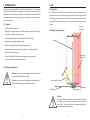
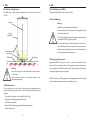
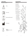
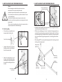
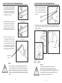
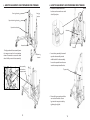
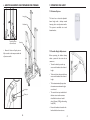
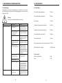
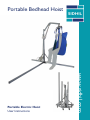
Portable Bedhead Hoist
www.sidhil.com
Portable Electric Hoist
User Instructions
CONTENTS
1. INTRODUCTION
4
1.1 Features
4
1.2 Warnings & Cautions
4
2. USE
5
2.1 Typical Use
2.2 Single Leg Configuration
2.3 Double Leg Configuration
2.4 Risk Assessment
2.5 Safe Working Load
2.6 General Warning
5
5
6
6
7
7
2.7 Regulatory Requirements
7
3. SYMBOL DEFINITION
4. PARTS IDENTIFICATION
5. HOIST ASSEMBLY AND PREPARING FOR USE
8
9
10
5.1 Hoist Assembly
10
6. HOIST DISASSEMBLY AND PREPARING FOR STORAGE
17
6.1 Hoist Disassembly
17
7. OPERATING THE HOIST
21
7.1 Electrical System
7.2 Variable Height Adjustment
7.3 Emergency Lowering Device
21
21
22
7.4 Hoist Lifting Safety Limit
22
8. CLEANING PROCEDURES
23
8.1 Infection Control
8.2 Decontamination
23
23
8.3 Cleaning the Sling
24
9. MAINTENANCE & TROUBLESHOOTING
25
9.1 General Maintenance
25
9.2 Fault Finding
26
10. SPECIFICATION
27
10.1 Hoist Data
27
10.2 General Electrical Data
28
10.3 Electrical Product Specific Data
28
11. OPTIONAL ACCESSORIES
29
12. WARRANTY
30
3
1. INTRODUCTION
2. USE
Thank you for purchasing a Sidhil Portable Electric Bedhead Hoist. The user manual
should be read carefully before operating the hoist in order to ensure safe operation
and maintenance. Please ensure that all instructions are fully understood and should
any questions arise concerning the operation or maintenance of the hoist please
contact your provider.
2.1 Typical Use
1.1 Features
• Portable electric bedhead hoist
• Designed for everyday indoor use as an aid to transfer a person from bed to chair,
wheelchair, commode or other similar item
• Increased maximum patient user weight of up to 24 Stone (152kg)
• Breaks down into easily manageable sections
Your Sidhil Portable Bedhead Hoist is intended for use within a patient home or
care home environment. It has been designed to provide a safe and easy method of
transferring a patient from bed to chair, wheelchair, commode or any other such item.
The adaptable hoist offers a product where a conventional ceiling track hoist cannot
be fitted.
Single or
double bed
2.2 Single Leg Configuration
Long leg
• Bespoke transport stand to aid storage and transportation
• Fitted with an electric actuator powered by a domestic mains power supply
• Integral manual lowering device
Non-Patient
transfer side
• Protected by BioCote® surface paint ensuring the product remains fully protected against the spread of harmful bacteria
1.2 Warnings and Cautions
Warnings in this user manual highlight potential hazards that if
disregarded could lead to injury or death.
Cautions in this user manual highlight potential hazards that if
disregarded could lead to equipment damage or failure.
Patient transfer side
Medium leg
Limiting screw
Short leg
Warning
The hoist must always be limited to the patient transfer side. Ensure
the limiting screw is located to the opposite side of the patient
transfer side. This prevents the arm from swinging onto the nonpatient side making the hoist unstable.
4
5
2. USE
2. USE
2.3 Double Leg Configuration
2.5 Safe Working Load (S.W.L)
An additional leg is required for this configuration and is supplied as an accessory
(HST14).
The safe working load of the hoist is 24 Stone (152kg).
2.6 General Warning
Long Leg
Warning
Misused electrical equipment can be hazardous.
Accessories that have not been approved or designed for use with
the hoist must not be used.
Single or
double bed
The hoist should always be limited to a patient transfer side unless
two medium (HST13/307) legs are deployed.
The hoist should always be positioned away from direct heat i.e.
away from radiators, fan heaters or any other external heat source.
Particular attention should be made to ensure the electrical control
box is not positioned close to a heat source.
Patient transfer
to both sides
Medium leg
Medium leg
DO NOT ALLOW BOOM ARM IN THIS AREA
Warning
Ensure the limiting screw is removed to allow the boom to move in
a 170° motion.
Do not permit the hoist arm to be operated beyond the area
indicated as shown above.
2.7 Regulatory Requirements
Regulations (LOLER ’98) require that carers are trained in accordance with this
directive in order to operate the hoist. This user guide complements this training; it
is not a substitute and is offered for guidance only. Should training be required please
contact your equipment supplier or provider.
LOLER ’98 states that all lifting equipment is thoroughly examined at six monthly
intervals and all examination records are retained for inspection.
2.4 Risk Assessment
Prior to patient/carer use of the hoist a comprehensive risk assessment must be
performed on a patient by patient basis. A risk assessment should include, but is not
limited to;
• The weight of the patient - not exceeding 24 Stone (152kg)
• Falling out of the bed/sling during patient transfer
• Small children (and adults)
• Point of transfer (deploying a single or double leg configuration)
• Unauthorised persons
6
7
3. SYMBOL DEFINITION
4. PARTS IDENTIFICATION
The following symbols are found on this hoist:
1. Long Leg (HST13/301)
2. Medium Leg (HST13/307)
3. Short Leg (HST13/302)
Warning
1
4. Transport Stand (HST13/TS)
5. Top Tube Assembly (HST13/311)
6. Boom Assembly (HST13/312)
7. Spreader Bar (7000)
5
8. Middle Tube Assembly (HST13/134)
6
9. Base Assembly (HST13/310)
Refer to user guide
10. CB6S Control Box (CONTROL/089)
11. LA44 Actuator (ACTU/045)
2
12. Electrical Pack (included - not shown)
- Handset (CONTROL/088)
- Actuator Cable (CABLE/015)
Maximum user weight & safe working load
3
- Mains Lead (CABLE/032)
- Cable Retainer (CABLE/089)
- Blanking Plug (CONTROL/030)
- User Guide (INSTRUC/HST13)
Place of manufacture
8
4
11
W.E.E.E Label
(Do not discard in general waste, follow local
recycling policy)
8
7
9
10
9
5. HOIST ASSEMBLY AND PREPARING FOR USE
5. HOIST ASSEMBLY AND PREPARING FOR USE
Caution
Unscrew hand wheel to
release base assembly
Before attempting to assemble the hoist please ensure these
instructions have been read and clearly understood.
It is advisable to assemble the hoist with a second able bodied person.
Prior to assembly ensure all items are provided as indicated in Section
4 – ‘Parts Identification’.
Clear the area of any obstructions and ensure the surface is level.
Ensure the castor brakes are applied prior to removing items from the
transport stand.
Base assembly
(HST13/306)
Take care when disassembling each part from the transport stand, as
each part/component is of considerable weight.
• Position the base assembly at the head end of the bed, ensuring the floor area is
clear of obstacles and the surface is level.
5.1 Hoist Assembly
•
A 5mm allen key is provided on the
transport stand to aid assembly.
• Offer the three stabilising legs (1 x short, 1 x medium & 1 x long leg) to the base
assembly. Ensure the longest leg is positioned to fit underneath the bed. Ensure
the medium length leg is inserted into the base assembly on the patient transfer
side. Insert the shortest leg to the opposite side. Secure all legs with the 5mm
allen key.
5mm allen key
• When fitting a HST13 (accessory medium leg) in place of the short leg, leave the
short leg on the transport stand.
•
Using the 5mm allen key loosen all
fastenings to enable removal of parts
from the transport stand.
•
Loosen the hand wheel on the
transport stand that holds the base
assembly in place and then lift this off
the stand and carefully place flat on
the floor.
Base assembly
(HST13/310)
Medium leg
(HST13/307)
Long leg
(HST13/301)
Short leg
(HST13/302)
Loosen fixings to
remove legs
10
Bolts to secure
legs in position
11
5. HOIST ASSEMBLY AND PREPARING FOR USE
5. HOIST ASSEMBLY AND PREPARING FOR USE
•
•
•
•
The levelling foot can be adjusted
to suit varying and uneven floor
surfaces. Ensure the assembled hoist
base and legs are completely stable
on the floor surface by adjusting the
levelling foot as necessary.
Ensure the boom is fully secure
within the top assembly and the
lynch pin is fully engaged into the
clevis pin, to proceed in fitting the
actuator.
Lynch Pin
(PIN/001)
Levelling foot in fully
lowered position
Ensure the limiting screw is loosened
sufficiently to insert the top assembly
(including boom & spreader bar)
into the base assembly. Locate and
position within the central column.
Clevis Pin
(CP/003)
• Ensure the top of the actuator is fitted and secured to the boom arm first with the
clevis and lynch pins. The base of the actuator is subsequently offered to the hoist
upright and secured.
Ensure the limiting screw in the
correct position to limit movement
of the boom to the patient side of
the bed only. Ensure the transport
stand that holds the base assembly is
in place and then lift this off the stand
and carefully place flat on the floor.
Levelling foot in
raised position
Top of actuator
Boom arm
Limiting screw
positions
Clevis Pin
(CP/003)
Warning
• Ensure the boom is supported when fitting the top assembly, to
prevent clashing with the central column and causing damage.
• Ensure the limiting screw is positioned correctly to limit
the arm movement to the patient transfer side of the bed
only.
12
Lynch Pin
(PIN/001)
Caution
Do not hang the actuator from the bottom pivot.
Do not allow the actuator to swing from the top pivot.
Ensure the actuator is supported at all times whilst being assembled.
Ensure the body of the actuator is positioned in the correct .
orientation to prevent collision with a wall.
13
5. HOIST ASSEMBLY AND PREPARING FOR USE
5. HOIST ASSEMBLY AND PREPARING FOR USE
• Locate the locking ring on the
underside of the actuator and turn
into the unlocked position.
• Route the control box cable to the
actuator securing the wire into the
clips provided.
Locking ring
• Position and secure the cable into the
socket. Holding the locking ring,
turn clockwise to fully lock at 90°.
• Plug the handset cable into Port 5 on
the control box socket.
Actuator cable inserted
Control box
• Plug the opposite end of the cable
into Port 1 on the control box.
Handset cable
Actuator cable
Control box
14
15
5. HOIST ASSEMBLY AND PREPARING FOR USE
6. HOIST DISASSEMBLY AND PREPARING FOR STORAGE
Caution
Actuator
Port
Ensure all cables are disconnected from the power supply and
control box prior to dismantling the hoist.
Handset
Port
Mains
Port
Power
Light
6.1 Hoist Disassembly
• Remove the cable retainer from the
control box by un-clipping with a flat
bladed screw driver.
• Clip the cable retainer into the control box in the orientation shown
to prevent the cables loosening. To
attach the retainer ensure to feed
the plug cables through the relevant
slot and push the retainer around the
plug. Clip the retainer into the control box to secure.
• Remove the mains cable by placing
a flat bladed screw driver into the
power port slot to dislodge the tabs on the red locking ring. Once
dislodged, the mains cable can be
released.
Cable retainer
• Attach the mains cable to the control
box, by lining up the 2 pin male connector with the 2 pin female port
on the control box. Ensure to engage
the red retention clip. Plug the three
pin plug to a domestic power supply.
Spring clip
Plastic washer
• The spreader bar is pre-assembled
to the boom. However, should the
spreader bar be removed, attach the
bar to the end of the boom arm using
the pin, washers and spring clips.
Ensure a washer is positioned at each side
of the boom arm and the spring clips are
fully located.
• Separate the hoist into its individual
parts to locate on the transport stand.
• The hoist is now ready to use.
16
17
6. HOIST DISASSEMBLY AND PREPARING FOR STORAGE
Short leg location
Long leg
location
6. HOIST DISASSEMBLY AND PREPARING FOR STORAGE
• Position the actuator within the brackets as shown and secure with
clevis & lynch pins.
Bracket
‘Spare’ medium leg location
Spreader bar location
Actuator
Actuator location
• Firstly, position the base assembly onto
the transport stand in the orientation
shown. Remember to secure the hand
wheel to fully secure the base assembly.
Bracket
Medium leg
location
Base assembly
positioned on
transport stand
• Insert the top assembly, boom and
spreader bar assembly into the middle tube of the base assembly.
Locate the spreader bar and secure
onto the transport stand bracket.
Top assembly
• Ensure all legs are positioned in the
correct location tubes. Secure legs into their respective tube by
tightening the leg bolt.
18
19
6. HOIST DISASSEMBLY AND PREPARING FOR STORAGE
7. OPERATING THE HOIST
7.1 Electrical System
Long leg
Medium leg
Typical leg bolt to
secure into tube
The hoist has an electrical adjustable
boom height with a backup manual
lowering device to aid patient transfer.
The system is controlled via a touch
button handset.
Short leg
• Ensure all clevis and lynch pins are
fully secured to the transport stand and
all parts are stable.
7.2 Variable Height Adjustment
Before operating the handset always
advise a patient of the action due to
commence.
• To raise the hoist, depress the up
arrow on the handset to the desired
height.
• To lower the hoist, depress the down
arrow on the handset to the desired
height.
Lynch pin
Clevis pin
• The hoist automatically stops when
the maximum or minimum heights
are achieved.
• The control box is pre-installed with
software to cut-out the actuator
should the hoist be over loaded above 24 stone (152Kg) safe working
load (SWL).
• Ensure the handset is located on the
handset holder when not in use.
20
21
7. OPERATING THE HOIST
8. CLEANING PROCEDURES
7.3 Emergency Lowering Device
8.1 Infection Control
• In case of power failure, the actuator
incorporates a mechanical lowering
device to lower a patient suspended in
the hoist.
Your hoist comes with an antibacterial additive incorporated into
the powder coated metalwork. Biocote® inhibits the growth of
bacteria on the surface of the hoist frame. It is effective against a
wide range of both gram positive and negative bacteria as well as
fungi. Examples of bacteria that Biocote® is resistant to include:
• Bacillus Subtilis
• To operate, twist the manual device in
a clockwise direction to lower the hoist.
• Staphylococcus Aureus (MRSA)
• Escerichia Coli 0157
Mechanical
lowering device
• Always ensure a patient is aware
when lowering the hoist manually.
• Streptococcus Faecalis
• Salmonella Enteritides
• Listeria Monocytogenes
Warning
7.4 Hoist Lifting Safety Limit
• The control box on the Sidhil Electric Hoist contains an electronic current limiter.
This will ensure the hoist will only ever lift the maximum 24 Stone (152kg) load.
• The current limiter will be triggered when the hoist has been loaded above and
beyond 24 Stone (152kg). When overloaded, the hoist will have a stop start motion
within the final third of the lifting range with the up button depressed on the handset.
• Should this occur lower the hoist immediately.
22
Biocote® is an aid to keeping your hoist infection free but it does not
substitute the need for the hoist to be cleaned at regular intervals.
Always disconnect the control box from the main power supply prior
to cleaning.
8.2 Decontamination
Infection control and routine cleaning must be carried out in accordance with your
local infection control policy or regulatory body.
Warning
Always disconnect the hoist from the main power supply prior to
cleaning.
23
8. CLEANING PROCEDURES
9. MAINTENANCE & TROUBLESHOOTING
9.1 General Maintenance
These instructions apply to all accessories apart from soft products (e.g. slings).
• All surfaces to be wiped down with a disposable soft cloth moistened with a mild
detergent and diluted in warm water (40°C).
• The hoist should be cleaned by starting with the cleanest parts of the frame and
systematically moving to the dirtiest parts. Extra care should be taken around
areas where excess dirt or dust may gather.
• The cloth should be changed during the cleaning process if it becomes soiled.
Only authorised service personnel or Sidhil service engineers should carry out repairs
or service activities. Failure to do so may result in the manufacturer’s warranty
becoming void.
The hoist must be serviced every six months, as a minimum and records of
the inspections maintained and kept for review. Sidhil also recommends that the
carer performs frequent visual and operational inspections. If there are any signs of
damage or the hoist is not performing as it should, withdraw it from service until the
hoist has been repaired and is fit for use again.
• Rinse down with clean water to remove detergent residue.
• Wipe surfaces down with 1,000 parts per million chlorine solution (0.1%).
Warning
Always disconnect the hoist from the main power supply prior to
performing any maintenance procedures.
• Dry off with a paper towel.
• Always ensure the cleaned parts are allowed to dry before attaching a sling.
Note: If any of the 3 stages stated above (detergent, rinse down & chlorine solution)
are omitted or combined it will reduce the effectiveness of the clean.
In cases of blood spills or other bodily fluids it is recommended that a chlorine solution
of 10,000 parts per million (1%) is used instead.
Note: The use of neat bleach or similar surface cleaners are not recommended as
damage may be caused to the cleaned surfaces.
Alternatively, Sidhil recommend the use of Chlor-clean tablets. Follow the
manufacturer’s instructions for concentration guidelines and instructions for use.
Refer to the Sidhil infection control policy, copies are available from Sidhil Ltd. Contact
details can be found on the back of this booklet.
Periodically:
• Check for any signs of tearing, split seams or other forms of damage to the sling.
• Check that the spreader bar rotates freely without excessive play.
• Check that the frame is mechanically sound.
• Check that all nuts, bolts and fasteners are tight and that none are missing or incomplete.
• Check that all the clevis pivot pins are secure and retained with the appropriate
lynch pins.
• Ensure the stabilising legs are fully secure.
Disposal of components must comply with local policy.
8.3 Cleaning the Sling
Please review the user instructions supplied with the sling for cleaning guidelines.
24
25
9. MAINTENANCE & TROUBLESHOOTING
10. SPECIFICATION
9.2 Fault Finding
10.1 Hoist Data
Listed below are a set of electrical faults that may occur within the service life of the
hoist. If a fault does occur please try the following suggestions, as these may help in
diagnosing the fault.
Overall width (single configuration)
2022mm
Overall width (double configuration)
2834mm
Overall length
1974mm
Spreader bar (highest position from floor)
1822mm
Spreader bar (lowest position from floor)
1083mm
Warning
Do not use the hoist until the fault has been resolved.
Fault
Possible Cause
Remedy
Hoist does not raise or lower.
Mains lead not plugged into
the mains supply.
Check that mains lead is
plugged into the mains supply
and the supply is switched on.
Mains lead not plugged into
the control box or is only
partially plugged in.
Check that mains lead is fully
located into the control box.
Overall height (floor to top of boom)
2048mm
Fuse has blown in the mains
plug.
Check the power light is
illuminated on the control box
and replace the 5A fuse if
necessary.
Central column height
1665mm
Actuator or handset leads are
unplugged or only partially
plugged in.
Check that both leads are fully
plugged into the control box.
Central column height (to remove during assembly) 2100mm
Actuator has reached its
maximum or minimum stroke.
Depress each button on
the handset to assess hoist
movement. Should the hoist
be at its highest position, lower
using the emergency lowering
nut on the actuator and contact
your supplier.
Damage to mains cable,
actuator cable or handset
cable.
Turn off at the mains and
contact your supplier.
Damage to actuator.
Maximum load exceeded.
The hoist fails mid operation.
The duty cycle of the hoist is
being exceeded. Ensure that
the maximum SWL has not
been exceeded. Lower the
hoist using the lowering nut or
the handset and allow the
control box to cool down.
The patient is above the 24
Stone (152kg) SWL.
Lower patient fully using the
emergency lowering nut or the
handset and do not exceed the
SWL.
26
Safe working load (user weight)
Product weight:
152kg (24 stone)
Hoist on transport stand 62 kg
Hoist
50 kg
27
11. OPTIONAL ACCESSORIES
10. SPECIFICATION
10.2 General Electrical Data
General voltage in
230V AC ±10%, 50Hz
Safety standards EMC
BS EN 60601-1-2:2006 (Medical Electrical System)
Electrical shock protection
Liquid ingress protection
Universal Sling (Small)
HST09/M
Universal Sling (Medium)
HST09/L
Universal Sling (Large)
HST09/XL
Universal Sling (X- Large)
HST10/S
Commode Sling (Small)
HST10/M
Commode Sling (Medium)
HST10/L
Commode Sling (Large)
HST10/XL
Commode Sling (X- Large)
HST11/S
Head Support for Universal Sling (Small)
HST11/M
Head Support for Universal Sling (Medium)
HST11/L
Head Support for Universal Sling (Large)
IP54
The electrical system is only suitable for use when:
Ambient temperature
+5° to +40°C
Humidity
HST09/S
20% - 90% at 30°C
10.3 Electrical Product Specific Data
Product: LA44 LINAK Actuator
Article no: 442205+5L2000A0
Thrust: 12000N
Speed: 10.4/6.0 mm/s
Stroke length: 200mm
Installation length: 548mm
Motor: 24V DC standard
Protection class: IPX4
Colour: Grey
Product: Mains Cable
Article no: 912049 (CONTROL/032)
Cable length: 3.2 Mtr
Extra feature: Locking O Ring
Colour: Black PVC
Product: LA44 LINAK Actuator Cable
Article no: 0964424-0500
Cable length: 500mm straight
Colour: Grey
Product: CB6S LINAK Control Box
Article no: CB6217-00
Mains voltage: 230V AC
Output voltage: 24V DC
No. of channels: 2
Duty cycle: 10% (or 6 min./hour)
Current cut-off: Special S/W
Protection class: IPX4
Colour: Grey
Product: HB80 LINAK Handset
Article no: HB8X072-00
No. of channels: 1
Cable length: 600mm Coiled
Protection class: IPX4
Colour: Grey PU
28
29
12. WARRANTY
Sidhil Ltd guarantees this product is free from defects in material and workmanship
under normal use for 3 years (1 year parts and labour, 2 further years for parts only)
from the date of purchase from Sidhil Ltd and its subsidiary companies or its authorised
dealers. All implied warranties, including but not limited to those implied warranties
of fitness and merchantability, are limited in the total duration of three years from
date of purchase. Proof of purchase must be presented with any claim. Except as
provided herein, Sidhil Ltd, product warranty does not cover damage caused by
misuse or abuse, accident, the attachment of any unauthorised accessory, alteration
to the product, or any other conditions whatsoever that are beyond the control of
Sidhil Ltd. Sidhil Ltd and its subsidiary companies shall have no liability or responsibility
to the customer or any other person or entity with respect to any liability, loss or
damage caused direct or indirectly by use or performance of the product or arising
out of any breach of this warranty, including but not limited to any damages resulting
from inconvenience, loss of time, property, revenue, or profit or any indirect, special,
incidental or consequential damages, even if Sidhil Ltd or their subsidiary companies or
authorised dealers has been advised of the possibility of such damages.
In the event of a product defect during the warranty period you should contact Sidhil
Ltd or their authorised dealer who will at its option unless otherwise provided by law;
a) correct the defect by product repair without charge for parts and labour b) replace
the product with one of the same or similar design or c) refund the purchase price. All
replaced parts and products on which refund is made become the property of Sidhil Ltd.
New or reconditioned parts and products may be used in the performance of warranty
service. Repaired or replaced parts and products are warranted for the remainder
of the original warranty period. You will be charged for repair or replacement of the
product made after the expiration of the warranty period.
This warranty does not cover; a) damage or failure by or attributes to acts of God,
abuse, accident, misuse, improper or abnormal usage, failure to follow instructions,
improper installation or maintenance, alterations, lightning or other incidence of excess
voltage or current, b) any repairs other than those provided by a Sidhil Ltd authorised
technician, c) consumables such as fuses, d) cosmetic damage, e) transportation,
shipping or insurance costs or f) costs of product removal, installation setup service
adjustment or re-installation.
This limited 1 year warranty gives you specific legal rights and you may also have other
rights.
Sidhil Ltd cannot be held responsible for any injury or incident which relates to the use
of this hoist in conjunction with accessories manufactured by companies other than
Sidhil Ltd.
All products carry the CE mark in accordance with EC Directive on Medical Devices
(93/42/EEC).
Sidhil has a policy of continual product improvement and reserves the right to amend
specifications covered in this brochure.
No part of this brochure may be reproduced without the written approval of Sidhil Ltd.
30
CONTACT INFORMATION
Tel: 01422 233000 Fax: 01422 233010
Email: [email protected] www.sidhil.com
Sidhil Business Park, Holmfield, Halifax, HX2 9TN
A member of the Siddall & Hilton Ltd. Group of Companies
(93/42/EEC)
Certificate No. FM14550
INSTRUC/HST13 - 09.01.12 - Rev - 2