1
Test Equipment Solutions Datasheet
Test Equipment Solutions Ltd specialise in the second user sale, rental and distribution of
quality test & measurement (T&M) equipment. We stock all major equipment types such as
spectrum analyzers, signal generators, oscilloscopes, power meters, logic analysers etc from
all the major suppliers such as Agilent, Tektronix, Anritsu and Rohde & Schwarz.
We are focused at the professional end of the marketplace, primarily working with customers
for whom high performance, quality and service are key, whilst realising the cost savings that
second user equipment offers. As such, we fully test & refurbish equipment in our in-house,
traceable Lab. Items are supplied with manuals, accessories and typically a full no-quibble 2
year warranty. Our staff have extensive backgrounds in T&M, totalling over 150 years of
combined experience, which enables us to deliver industry-leading service and support. We
endeavour to be customer focused in every way right down to the detail, such as offering free
delivery on sales, covering the cost of warranty returns BOTH ways (plus supplying a loan
unit, if available) and supplying a free business tool with every order.
As well as the headline benefit of cost saving, second user offers shorter lead times, higher
reliability and multivendor solutions. Rental, of course, is ideal for shorter term needs and
offers fast delivery, flexibility, try-before-you-buy, zero capital expenditure, lower risk and off
balance sheet accounting. Both second user and rental improve the key business measure of
Return On Capital Employed.
We are based near Heathrow Airport in the UK from where we supply test equipment
worldwide. Our facility incorporates Sales, Support, Admin, Logistics and our own in-house
Lab.
All products supplied by Test Equipment Solutions include:
- No-quibble parts & labour warranty (we provide transport for UK mainland addresses).
- Free loan equipment during warranty repair, if available.
- Full electrical, mechanical and safety refurbishment in our in-house Lab.
- Certificate of Conformance (calibration available on request).
- Manuals and accessories required for normal operation.
- Free insured delivery to your UK mainland address (sales).
- Support from our team of seasoned Test & Measurement engineers.
- ISO9001 quality assurance.
Test equipment Solutions Ltd
Unit 8 Elder Way
Waterside Drive
Langley
Berkshire
SL3 6EP
T: +44 (0)1753 596000
F: +44 (0)1753 596001
Email: [email protected]
Web: www.TestEquipmentHQ.com
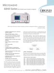
6840 series
Microwave
6840
series
Analyzers
Microwave
provide
an
RF and Microwave System Analyzers
System
integrated
solution to component and subsystem
testing
• Integrated synthesized source, scalar
and spectrum analyzer
• 3 GHz, 8.4 GHz, 20 GHz, 24 GHz and
46 GHz frequency versions
• Precision scalar network measurements
with high dynamic range
• Spectrum analyzer with full range
tracking generator
• Offset tracking on network
measurements
• Group Delay option
The 6840 series RF and microwave system analyzers are a powerful new tool
for the microwave industry. Integrated into a single instrument are a
synthesized source, a three input scalar analyzer and a synthesized spectrum
analyzer. The internal source can be used as a simple CW output, as a swept
source for scalar measurements, as a tracking generator with the spectrum
analyzer and as an offset tracking source for network measurements on
frequency translation devices.
This flexibility simplifies a range of previously complex but commonly made
measurements. The receiver in the spectrum analyzer can be used as a tuned
input for high dynamic range scalar measurements. The FM option adds
frequency modulation to the source. The Group Delay option allows
simultaneous measurement and display of group delay and amplitude
response, and includes the frequency modulation option.
• FM option
• Complete solution to comprehensive
component and subsystem
characterization
• Real time transmission line Fault
Location with 0.1% accuracy
• EEPROM corrected scalar detectors for
accurate measurements
• Applications interface allows guided and
automatic testing
1 Series - 8 Instruments
The range covers five frequency bands in various convenient combinations of
source and spectrum analyzer frequencies, enabling for example the harmonic
content of microwave radios to be measured.
• Modular design for rapid service
• 3.5 in disk drive for results storage
a d v a n c i n g
6840 series Microwave System Analyzers
6841
6842
6843
6844
6845
6846
6847
6848
1 MHz to 3 GHz Scalar Analyzer with 4.2 GHz Spectrum Analyzer
10 MHz to 8.4 GHz Scalar Analyzer with 20 GHz Spectrum Analyzer
10 MHz to 20 GHz Scalar Analyzer with 20 GHz Spectrum Analyzer
10 MHz to 24 GHz Scalar Analyzer with 24 GHz Spectrum Analyzer
10 MHz to 46 GHz Scalar Analyzer with 46 GHz Spectrum Analyzer
10 MHz to 8.4 GHz Scalar Analyzer with 24 GHz Spectrum Analyzer
10 MHz to 20 GHz Scalar Analyzer with 26.5 GHz Spectrum Analyzer
1 MHz to 3 GHz Scalar Analyzer with 20 GHz Spectrum Analyzer
w i r e l e s s
t e s t
Synthesized Source
The synthesized source has low phase noise and 1 Hz frequency
resolution. VCOs are used for frequencies above 3 GHz and an
integrated RF synthesizer for the 1 MHz to 3 GHz range.
Optionally increased output power is available from 3 to 24 GHz.
Internal filtering results in excellent harmonic performance of
<-55 dBc for improved scalar measurement accuracy. Optional step
attenuators are available to set low output powers for amplifier or
receiver testing.
In CW mode the source can be used for local oscillator substitution.
A power sweep is provided for amplifier gain compression testing.
External FM can be applied by connecting a generator to the rear
panel. With the FM option, an internal generator provides
frequency modulation of the source.
components, subsystems and systems.
Continuous full band sweeps simplify harmonic and spurious
measurements. The low distortion front end combined with wide
dynamic range ensures that even on full span sweeps, spurious
measurements to better than -60 dBc can be performed. High
sensitivity at microwave frequencies is ensured by the use of
wideband oscillators, this reduces the harmonic number used in the
front end mixer.
The spectrum analyzer is fully featured with FM demodulator and
built in loudspeaker. This is ideal for locating and identifying the
source of interfering transmissions. Individual signals can be
precisely identified by use of the internal frequency counter.
When used with the scalar analyzer the source provides a swept
synthesized output for frequency characterization of components
and systems. It can also be used as a spectrum analyzer tracking
generator to 46 GHz. The source can be set to any frequency offset
or frequency multiple of the receiver tuned input. This powerful
feature simplifies measurements of mixers, upconverters and
down-converters that have frequency translation.
Scalar Analyzer
The three input scalar analyzer provides network characterization of
components and systems. Simultaneous measurement of insertion
and return loss are displayed on the 6840 color screen. Excellent
measurement accuracy is assured by the use of EEPROM corrected
detectors. Each detector is individually characterized for linearity
and frequency response to provide a measurement accuracy close to
that achieved with a power sensor. A range of autotesters with high
directivity is available for return loss measurements.
It is also possible to make scalar measurements with a tuned input.
A tuned input gives improved dynamic range. Insertion loss
measurements of >80 dB are possible.
Amplifier intermodulation measurement
Optimized operation is provided by the coupling of the fundamental
analyzer parameters of resolution bandwidth, sweep speed, video
filter and input attenuation. These parameters are automatically set
for optimum sweep speed and dynamic range. For specific
applications the user can manually overide the coupled functions.
Autotune automatically sweeps the full span of the spectrum
analyzer and then displays the largest signal at the center and top of
the screen. Markers can also be used to select any signal and display
it at the center of the screen.
The integral source enables network measurements in normal
tracking mode or by applying a frequency offset and/or
multiplication factor. Any frequency offset can be supported. This
facility makes measurements faster and easier than assembling
together separate instruments and a PC controller.
External mixers extend the frequency range to 110 GHz.
Bandpass filter insertion loss measurement
Spectrum Analysis
The 6840 variants contain an integral synthesized spectrum
analyzer with 3 MHz to 1 kHz resolution bandwidth filters, >80 dB
instantaneous dynamic range and an excellent 3rd order
intermodulation intercept point. 6840 series are designed to make
routine spectrum measurements on RF and microwave
Fault Location
Fault location software is standard on all 6840 series instruments.
Many modern communication systems rely on a coaxial or
waveguide feed between the transmitter and antenna. The fast fault
location facility of the 6840 can quickly locate the position of faults
causing poor return loss in the feed, which can seriously impact
system performance.
Measurement resolution and accuracy is assured by the use of a
synthesized source with up to 1601 measurement points.
The applications facility can reduce the incidence of operator error,
improve measurement repeatability, provide guidance to infrequent
users or simplify complex test procedures.
Fault location measurement of a coaxial feed and antenna
Color Display
A large TFT color display is fitted to the 6840 as standard displaying
up to four measurements on two channels. Scalar and spectrum
measurements can be displayed simultaneously on independent
channels. Alternatively two spectrum channels can be shown with a
wide and narrow frequency sweep. This could be used to scan a
frequency spectrum for interfering signals whilst simultaneously
displaying the wanted carrier.
Group Delay
The Group Delay option allows the simultaneous measurement and
display of group delay and amplitude response over the full
frequency range of the instrument. Components and assemblies
including frequency translation devices can be readily characterized
for ripple and variation from linear and parabolic variation using the
powerful and easy to use marker functions. Measurement in any
operator-specified sub-band within the passband can be displayed
as maximum peak to peak ripple in both amplitude and group delay,
maximum slope and maximum rate of change of slope.
Dual channel display, showing wide band and narrow band frequency
sweeps
Comprehensive Markers
Up to eight markers are available. The marker menus provide the
tools that are most commonly used in each of the measurement
modes.
Amplitude and delay response of a filter
Simplified User Interface
Integration of a source, spectrum analyzer and scalar analyzer into a
single instrument has many benefits. The operator uses a single
interface to set up any measurement. This saves time and is easier
than writing software to perform complex measurement tasks, such
as frequency offset network measurements.
Eight softkeys give rapid access to all commonly used parameters.
Softkeys are shaped to inform the user of the action that the key will
perform, e.g. enter data, select from list, move to another menu or
immediate action. All commonly accessed functions are no more
than one level deep, so that the instrument operation is easily learnt.
Applications Interface
An applications interface is built into the 6840 series which allows
the user to create their own measurement routines and guide the
operator through the test procedure. For example it can display on
the 6840 screen how to set up the measurement, lead the operator
through a calibration, show where to connect the device under test
and then test the device’s performance against predefined limits.
a d v a n c i n g
Harmonic measurement with dynamic marker table
In spectrum mode the markers identify the frequency and level of a
signal, position signals on the display and measure relative signal
values. A peak search feature places markers on the eight highest
signals displayed for spurious signal identification. A table displayed
below the traces shows the values of all eight markers dynamically.
In scalar mode markers automatically calculate peak to peak ripple,
N - dB bandwidth, -1 dB compression point and find the maximum
and minimum signal levels. This simplifies device characterization
and reduces test time.
w i r e l e s s
t e s t
For fault location measurements the next peak left/right feature
identifies the position and magnitude of each of the discontinuities
along the transmission line. The peak find softkey quickly locates
the biggest discontinuity on the line.
Fast Field Repair
6840 has a modular architecture with modules slotted onto a
common mother board. In the event of a module failure the
instrument can be repaired by module replacement to reduce
instrument downtime. Following a repair, software routines realign
the replaced module.
Future Proof
The 6840 series microwave system analyzers have been designed to
expand and adapt to changing test requirements. A standard
instrument has capacity for additional modules. As future options
are added, the flexibility and capability of the 6840 platform will
expand. This ensures that investment made in the 6840 series today
will provide a basis for future test needs.
For Design Engineers
For designers of components and subsystems the 6840 provides a
powerful and flexible analysis tool. Devices such as filters,
amplifiers, mixers, attenuators and oscillators can be characterized
with a single test instrument. This flexibility reduces design cycles
as the need to make instrument interconnections is reduced. 6840
has a low noise source for LO substitution and swept frequency
measurements. The use of EEPROM detectors ensures accurate
scalar measurements. Amplifiers can be precisely characterized for
gain compression, output power and frequency response. The use
of a tuned input can give >80 dB dynamic range for filter testing and
the accessory autotesters, with 40 dB directivity, ensure accurate
return loss results. The spurious and harmonic output of oscillators
can be measured with the wide span high dynamic range spectrum
analyzer.
Manufacturing Test
To the production manager the 6840 offers reduced programming
time, reduced test time and simplified archiving of results. 6840 is
fully compliant with the IEEE 488.2 GPIB standard. A full 401 data
points can be transferred over the GPIB in typically <50 ms.
Individual data points can be repetitively read in typically 10 ms.
This enables full results archiving with minimal time penalty.
A single instrument replaces ‘rack and stack’ alternatives which
makes program generation simpler. Rack space is also reduced.
Continuity of test is essential in a production environment. A failed
test system can result in expensive loss of output. 6840 with its field
replaceable modules minimizes any output loss due to test system
failure.
Installing and Maintaining Systems
During the installation period of a microwave system it is always
necessary to revalidate key parameters. 6840 provides a
comprehensive solution for installation teams. It is housed in a
ruggedized case, has secure handles and can be supplied with a
protective carrying case.
For systems with long waveguide or coaxial feeds the 6840 is used by
the installation team to measure return loss and if necessary fault
location. The synthesized source with 1601 measurement points
ensures precise fault location measurements. The 6840 series
provides a tuned input that can be used for return loss and fault
location measurements. This measurement technique rejects
interfering signals from other transmitters, a common cause of poor
measurement performance in the field.
By archiving results onto disk, or the internal instrument memory,
the 6840 forms the basis of a preventative maintenance system.
Experience shows that degradation in the antenna feed is the major
source of system field failures. 6840 has the accuracy to monitor and
identify gradual system degradation with time.
Results Logging and Outputting
Measurement results can either be saved to internal non-volatile
memory or to 3.5 in disk. Traces saved onto disk can then be
archived or imported into a spreadsheet for viewing.
An alternative method for displaying results in a standard word
processor document or in a graphics package is to use the optional
MIPlot software. MIPlot captures the measurement data either via
the GPIB or from a saved trace on disk. This data can then be
embedded into a document and reformatted, colors changed,
markers and text added.
Specification
SOURCE
Functionality
Synthesized CW
Synthesized sweeper for use with scalar analyzer,
Tracking generator for use with spectrum analyzer.
Offset tracking generator for use with spectrum analyzer (offset by
scale or multiplication factor)
CW Power sweep.
External Frequency Modulation
Optional Internal Frequency Modulation in spectrum, scalar and
source-only modes.
Frequency Range
6841/6848, 1 MHz to 3 GHz
6842/6846, 10 MHz to 8.4 GHz
6843/6847, 10 MHz to 20 GHz
6844, 10 MHz to 24 GHz
6845, 10 MHz to 46 GHz
Resolution (Settable)
1 Hz
2 Hz
to 24 GHz
24 GHz to 46 GHz
CW Accuracy
(Frequency Standard error x Frequency) ± 10 Hz
-3 dB bandwidth, AC coupled mode
10 MHz - 3 GHz
<100 Hz to >1MHz typical
3 GHz - 46 GHz
<100 Hz to >500 kHz typical
Swept Accuracy (Typical)
300 ms Step Time
1 MHz to 3 GHz
3 GHz to 46 GHz
<20 kHz
<200 kHz
1 ms Step Time
1 MHz to 3 GHz
3 GHz to 46 GHz
<1 kHz
<10 kHz
10 ms Step Time
1 MHz to 3 GHz
3 GHz to 46 GHz
<100 Hz
<1 kHz
-3 dB bandwidth, DC coupled mode
10 MHz - 3 GHz
DC to >1 MHz typical
3 GHz - 46 GHz
DC to >500 kHz typical
Frequency Modulation Option 023, 022
Modulation signal sinewave, 0.1 Hz to 500 kHz, resolution 0.1 Hz
Other specifications as for External Frequency Modulation except:
Accuracy (1 kHz modulating frequency) 20 - 400 kHz deviation
±5 % of indication ±1 Hz excluding residual FM
Levelled Power Range
6841/2/3/4/6/7/8 standard
1 MHz to 3 GHz
-10 dBm to +10 dBm
3 GHz to 24 GHz -10 dBm to +5 dBm
6842/3/4/6/7/8 + option 030 (higher power)
1 MHz to 24 GHz -10 dBm to +10 dBm
6841/48 + option 010
1 MHz to 3 GHz
(110 dB Step Attenuator)
-120 dBm to +8 dBm
6842/3/6/7 + option 011 (70 dB Step Attenuator)
10 MHz to 3 GHz -80 dBm to +8 dBm
3 GHz to 20 GHz -80 dBm to +2 dBm
+ option 030 (higher power)
3 GHz to 20 GHz -80 dBm to +7 dBm
6842/3/4/6/7 + option 012
(90 dB Step Attenuator)
10 MHz to 3 GHz -100 dBm to +8 dBm
3 GHz to 24 GHz -100 dBm to +2 dBm
+ option 030 (higher power)
3 GHz to 24 GHz -100 dBm to +7 dBm
6845
10 MHz to 8 GHz -10 dBm to +8 dBm +10 dBm typ
8 GHz to 20 GHz -10 dBm to +5 dBm +7 dBm typ
20 GHz to 24 GHz -10 dBm to +4 dBm +6 dBm typ
24 GHz to 40 GHz -10 dBm to 0 dBm
+3 dBm typ
40 GHz to 46 GHz -10 dBm to 0 dBm typ*
* excluding the effect of connector moding
6845 + option 013 (70 dB step attenuator)
10 MHz to 8 GHz -80 dBm to +6 dBm +8 dBm typ
8 GHz to 20 GHz -80 dBm to +2 dBm +4 dBm typ
20 GHz to 24 GHz -80 dBm to +1 dBm +3 dBm typ
24 GHz to 40 GHz -80 dBm to -3 dBm
0 dBm typ
Note: For option 002 (Field Replaceable connectors) guaranteed
levelled output is reduced by 0.5 dB
Settable Power Resolution
1 MHz to 3 GHz, ± 0.7 dB
3 GHz to 24 GHz, ± 1.0 dB
24 GHz to 40 GHz, ±1.5 dB
Levelled Power Accuracy With Options 010, 011, 012, 013
1 MHz to 3 GHz
<±1 dB (± 0.3 dB ± 2% of attenuator setting in dB
whichever is greater)
3 GHz to 24 GHz
<±1 dB (± 1 dB ± 4% of attenuator setting in dB
whichever is the greater)
24 GHz to 40 GHz
<±1.5 dB (± 1 dB ± 4% of attenuator setting in dB
whichever is the greater)
Linearity (No Options Fitted, Option 030) Over Levelled Range
Relative to 0 dBm
1 MHz to 40 GHz <± 0.5 dB
Power Stability With Temperature Typical
1 MHz to 40 GHz <0.1 dB/oC
Harmonics and Sub-Harmonics Over Levelled Power Range
Harmonics
<70 MHz, <-25 dBc
70 MHz to 24 GHz, <-55 dBc
24 GHz to 40 GHz, <-20 dBc
Sub-Harmonics
1 MHz to 3 GHz, <-60 dBc
3 GHz to 24 GHz, none
24 GHz to 40 GHz, <-40 dBc
Spurious Signals (Typical)
0.01 dB
Power Sweep Range (from Maximum Levelled Power) Without
Attenuator
>20 dB
External Frequency Modulation
Peak deviation (1 V peak input)
10 MHz - 375 MHz
375 MHz - 750 MHz
750 MHz - 1.5 GHz
1.5 GHz - 3 GHz
3 GHz - 46 GHz
Internal Levelling Accuracy at 0 dBm (no options fitted)
1 kHz to 5 MHz
250 Hz to 1.25 MHz
500 Hz to 2.5 MHz
1 kHz to 5 MHz
20 kHz to 1 MHz
For carrier frequencies <375 MHz
Offset:
30 kHz to 150 kHz, <-50 dBc
150 kHz to 1 MHz, <-55 dBc
> 1 MHz, <-55 dBc
For carrier frequencies >375 MHz
Offset:
30 kHz to 150 kHz, <-50 dBc
150 kHz to 1 MHz, <-60 dBc
> 1 MHz, <-60 dBc
Accuracy (1 kHz modulating frequency) 20 - 400 kHz deviation
±3 % of indication ±1 Hz excluding residual FM
a d v a n c i n g
w i r e l e s s
t e s t
Phase Noise <dBc/Hz in CW mode
CW Freq
0.25 GHz
0.5 GHz
1 GHz
2 GHz
4 GHz
10 GHz
20 GHz
24 GHz
40 GHz
1 kHz
-86
-98
-92
-86
-80
-72
-66
-64
-63
Phase Noise <dBc/Hz
Frequency offset
10 kHz
100 kHz
-95
-108
-112
-134
-106
-128
-100
-122
-92
-100
-84
-90
-78
-82
-76
-80
-75
-79
Source Match (Typical)
1 MHz to 3 GHz, 15 dB
3 GHz to 20 GHz, 10 dB
20 GHz to 40 GHz, 8 dB
Output Connector
6841/2/3/6/7/8; Precision Type N, female
6844: Precision 3.5 mm, female
6845: Precision 2.92 mm, female
or optional field replaceable connectors
SPECTRUM ANALYZER
FREQUENCY
Frequency Range (Usable from 100 kHz)
6841, 1 MHz to 3 GHz (usable to 4.2 GHz)
6842, 6843, 6848, 10 MHz to 20 GHz
6844, 6846, 10 MHz to 24 GHz (usable to 30 GHz)
6845, 10 MHz to 46 GHz
6847, 10 MHz to 26.5 GHz (usable to 30 GHz)
Extendible for all units to 110 GHz in waveguide only with external
waveguide mixers. The 6840 series unit must be fitted with option
020.
Frequency Span Range
Full span to Zero span, plus any intermediate value
Start Frequency Accuracy
(start frequency x frequency standard error) ± frequency readout
resolution ± 3% of span ± 20% resolution bandwidth setting
Span Accuracy
Fully synthesized for spans of 20 MHz or less
± 3% for spans >20 MHz
Number of Measurement Points
Fixed 512
Frequency Readout Resolution
Span/512
Marker Readout Accuracy
As per start frequency accuracy
Sweep Speed
Auto coupled or user set, 10 ms/div to 50 s/div
Analyzer freq
10 MHz
4.2 GHz
(N=1 on the
8.6 GHz
(N=2 on the
18.5 GHz
(N=3 on the
38 GHz
(N=6 on the
Frequency offset
20 kHz
100 kHz
-90
-100
-90
-100
Harmonic Mixer)
-84
-94
-77
-87
-73 typ
-83 typ
Harmonic Mixer)
Harmonic Mixer)
Harmonic Mixer)
System Related Sidebands
<-65 dBc at offsets greater than 30 kHz from the carrier
AMPLITUDE
Maximum Input Amplitude
+20 dBm
Damage Level
+27 dBm @ >10 dB attenuation
+20 dBm @
0 dB attenuation
Input Return Loss (typical) with ≥10 dB of Input Attenuation
10 MHz to 3 GHz 20 dB
3 GHz to 12 GHz 12 dB
12 GHz to 40 GHz 10 dB
Input Connector
6841/2/3/8: Precision Type N, female
6844/6/7: Precision 3.5 mm, female
6845: Precision 2.92 mm female
or optional field replaceable connectors
Input Attenuator
Range 0 to 60 dB in 10 dB steps
Reference Level
Range +30 dBm to -99 dBm
Amplitude Scaling
Range 10 dB/div to 0.1 dB/div
Amplitude Accuracy at 0 dBm Reference Level and 0 dBm Input
(at selected bandwidth)
10 MHz to 3 GHz
± 1 dB
to 4.2 GHz*
± 1.5 dB
to 20 GHz
± 4.0 dB
to 24 GHz**
± 4.5 dB
to 40 GHz
± 5.0 dB
* does not apply to 6841, ** to 26.5 GHz for 6847
Incremental Reference Level Accuracy from +20 dBm to
-40 dBm (Typical)
±0.5 dB
Response Flatness (Typical)
±3.0 dB
Log Incremental Accuracy (Typical)
0.2 dB / 10 dB
Display Linearity
±1.5 dB over 8 divisions (10 dB/div)
Gain Compression (0 dB Attenuation)
<0.5 dB with -10 dBm at the input connector
Resolution Bandwidth Range
1 kHz to 3 MHz in 1, 3, 10 sequences
Resolution Bandwidth Accuracy
Millimeter waveguide, single diode harmonic mixers
± 20 %
Available for all 684X units, option 020 external mixer interface is
required.
Resolution Bandwidth Selectivity
60 dB / 3 dB ratio
1 kHz to 3 MHz 15:1
Resolution Bandwidth Switching Error
<0.25 dB
Video Bandwidth
1, 3, 10, 30, 100, 300, Hz
1, 3, 10, 30, and 100 kHz
Third Order Intermodulation Response (0 dB Attenuation)
<-70 dBc with 2 tones each -30 dBm, with
>50 kHz separation applied at the input connector
Third Order Intercept Point
Second Order Single Tone Intercept Point
>+45 dBm
Second Harmonic Distortion >40 MHz and @ -40 dBm
<-70 dBc for -40 dBm at the input connector with 0 dB attenuation
Residual Responses (Input Terminated with 50 Ω)
<-90 dBm
Other Input Related Spurii (0 dB Attenuation)
<-60 dBc with -10 dBm at the input connector
Displayed Average Noise Level in 1 kHz RBW, 30 Hz VBW, 0 dBm
Attenuation (Input Terminated with 50 Ω)
1 GHz
6 GHz
12 GHz
18 GHz
38 GHz
Model
Number
M42HW
M28HW
M22HW
M19HW
M15HW
M12HW
M10HW
Frequency
Range
18-26.5 GHz
26.5-40 GHz
33-50 GHz
40-60 GHz
50-75 GHz
60-90 GHz
75-110 GHz
Waveguide
Designation
WR42, WG20,
WR28, WG22,
WR22, WG23,
WR19, WG24,
WR15, WG25,
WR12, WG26,
WR10, WG27,
R220
R320
R400
R500
R620
R740
R900
Flange
Type
UG-597/U
UG-599/U
UG-383/U
UG-383/U
UG-385/U
UG-387/U
UG-387/U
A Diplexer (DPL.313A)is required for use with the mixers listed above.
It is supplied with two SMA (m) barrel adapters for IF and LO
interconnection to the spectrum analyzer Option 020 connectors and
a 1 meter long, high quality interconnecting cable for connection
between mixer and diplexer.
SCALAR ANALYZER
>+5 dBm
@
@
@
@
@
Accurate marker frequency readout
Multiple markers
Two independent channels
Scrollable center frequency, span and resolution bandwidth
Measurement of noise in a 1 Hz bandwidth
Auto-tune display set-up for CW signals
NBFM demodulator with audio output
Demodulated output displayed on screen
Speed 1 ms/div to 1 s/div
<-105 dBm
<-100 dBm
<-100 dBm
<-95 dBm
<-80 dBm typ
EXTERNAL MIXER INTERFACE (option)
LO output, 4.5 - 9.2 GHz @ +17 dBm typical
IF input, 479.3 MHz, maximum level -15 dBm typical
Connectors
SMA (female)
DEMODULATION
SYSTEM FEATURES
Frequency Range
As per source frequency range
Number of Inputs
3 detector inputs plus tuned input
Number of Measurement Points
User selectable from 2 to 1601
Applications
Return loss vs frequency
Insertion loss vs frequency
Fault Location
Voltage vs frequency
Group Delay vs Frequency (optional)
Detection Modes
AC and DC
Noise Reduction
Averaging, 1 to 1000
Smoothing, 0.01 to 20%
Power Measurements
Using scalar detectors
Detector Correction
Narrow band FM, <20 kHz
Display, kHz vs time
Audio output via speaker
Frequency response and linearity read from EEPROM for 6230A/L
and fault locators.
Support for 6230 and autotesters.
MEASUREMENT FEATURES
Frequency counter
Ability to display channel occupancy masks, user defined
a d v a n c i n g
w i r e l e s s
t e s t
INSERTION LOSS MEASUREMENTS
Measurement Dynamic Range, AC Scalar Detection, with 623XA
Detector
Max source output to -60 dBm
Max source output to -65 dBm (with averaging)
Typical values:
>65 dB (10 MHz to 40 GHz)
>75 dB (1 MHz to 3 GHz) only with 6232A
Measurement Dynamic Range, Tuned Input
Maximum source output to -75 dBm
Typically >80 dB (10 MHz to 17 GHz)
Measurement Update Rate
401 points in 270 ms with DC detection
Calibration
Through path calibration or short and short/open calibrations for
single ended insertion loss
Inputs
Single input or ratio
Accuracy (detector inputs and tuned input)
Linearity + mismatch
Linearity (applies after normalization)
Linearity (for Power Levels >-50 dBm) scalar detector inputs
±0.2 dB / 10 dB but not >0.5 dB in total
Linearity (tuned input)
Log incremental accuracy (typical)
0.2 dB/10 dB
Display Linearity
±1.5 dB over 8 divisions (10 dB/div)
RETURN LOSS MEASUREMENTS
Measurement Update Rate
401 points in 270 ms with DC detection
Calibration
Short, Open, Short/Open
Inputs
Single input or ratio
Accuracy
Linearity + directivity + test port mismatch
Linearity (for Power Levels >-50 dBm)
±0.2 dB / 10 dB but not > 0.5 dB in total
FAULT LOCATION MEASUREMENTS
Measurement Range
Up to 25 km depending on cable or waveguide loss
Units
Feet or meters
Number of Measurement Points
User selectable from 50 to 1601
Minimum Resolution
For two equal amplitude discontinuities using maximum sweep width
6841/8: 12.18 x Vr cm
6842/6: 4.32 x Vr cm
6843/7: 1.82 x Vr cm
6844: 1.51 x Vr cm
6845: 0.91 x Vr cm
Where Vr is the relative velocity factor for the transmission line
Measurement Update Rate
512 points in 250 ms, DC detection
Dynamic Range
DC detection 70 dB
AC detection 80 dB
Distance Accuracy
3 mm or 0.1% of range for a single fault
Transmission Line Database
Data supplied as standard
Required Accessory
624X series fault locator
or 658X series transmission line test head
or divider
GROUP DELAY
Measurement Range
±1 µs to ±10 µs
Resolution* (3 MHz aperture)
0.1 ns to 15 GHz
0.2 ns 15 to 30 GHz
0.3 ns 30 to 40 GHz
Absolute Accuracy* (3 MHz aperture)
±0.5 ns
*excluding effects of imperfect match
Relative Accuracy (for peak to peak measurement)
As Resolution (typical)
Scales
0.1 ns/div to 5 µs/div in a 1, 2, 5 sequence with increment keys
Keypad entry provides user scaling
Reference delay
Defaults to zero, user selectable
Reference position
User selectable, default is centre display
Delay offset
User entry of offset value
Trace displays
Simultaneous amplitude and group delay vs frequency
Absolute delay and “zoom” display vs frequency
Dual channel mode
Comparison over same frequency range at same centre frequency
Comparison over different centre frequencies
FREQUENCY STANDARD
Internal 10 MHz OCXO
GENERAL FEATURES
Number of Display Channels
2
Number of Measurements
4 (2 per display channel)
Number of Measurement Points
2 to 1601 for one trace, scalar
512 fixed, spectrum
Display Color active matrix TFT liquid crystal display with 16.5 cm (6.5
in) visible diagonal
Drift
Data Storage 3.5 in floppy disc drive, 1.44 Mb. Trace storage in DOS
format.
± 5 in 108 over 0 to 55°C
Ageing
Limits
± 2 in 107 per year (OCXO)
4 stores of 12 segments each. Each segment defines an upper limit,
upper and lower limits, or a point. Any store can be applied to any
trace.
External Frequency Standard
1 MHz or 10 MHz
Connector: BNC
MARKERS
8 per trace plus separate delta marker
REAR PANEL CONNECTORS
Marker Functions
RS-232
Marker, delta marker, minimum, maximum, search left, search right,
N-dB bandwidth (with center frequency), marker tracking.
9 way D-type connector, male
Baud rate 300 to 9600
Spectrum Analyzer
GPIB Interface
GPIB is IEEE 488.1 and 488.2 compatible. The interface has 2
functions.
-Instrument control with full Talk/Listen capability
-Control of plotter using HPGL. Plotter is buffered to permit
measurements to proceed whilst plotting.
10.7 MHz IF Output (from Spectrum Analyzer)
Connector: BNC
Find Peak / Next Peak (next highest amplitude
or next Left / Right) / Identify Peaks
MKR to CF
MKR to Ref Level
Counter / Set Resolution
Measure Relative to Carrier (dBc)
Search Left / Right
Delta MKR / Set Span / Fixed Delta
Scalar Analyzer
Frequency Standard In/Out BNC
10 MHz input or 10 MHz output selectable from front panel
Mod In/Out BNC
Frequency modulation input or output
Printer Output
25 way D-type connector
Parallel interface.
Drivers supplied for PCL DeskJet and LaserJet printers. Printer is
buffered to permit measurements to proceed whilst printing.
External Monitor
Standard VGA, 640 by 480 color output
15 way high density D-type female connector
Voltage Output (Auxiliary 9-pin Connector)
Settable for 0 to 10 V ramp, fixed voltage or chart recorder drive
Video Output (Auxiliary 9-pin Connector)
Output from spectrum analyzer detector
Bandwidth: as per RBW setting
External Levelling Input
Input voltage range: 0 to +1 V
Connector: BNC
Active marker Max / Min
Max / Min Tracking
Find PK-PK
PK-PK Tracking
Search Right / Left
Bandwidth / Optional CF / DF (Q)
dB / Octave, dB / Decade Readout
Delta Marker On / Off
-1 dB Gain Compression
Peak to peak delay between two markers
Max peak to peak delay in a user defined bandwidth
Deviation from linear between two markers
Deviation from parabolic between two markers
Fault Location
Find Max / Track Max
Next PK Right / Left
Set PK Level
Delta marker On / Off
General
Marker Table
Assign Active MKR / Position Active MKR
Set-up Markers (i.e. On / Off, Position)
Large Readout
All Off
Marker Resolution
Frequency: 6 digits or 1 Hz, user selectable
Power: 0.01 dB
a d v a n c i n g
w i r e l e s s
t e s t
Versions and Options
Voltage: 1 nV
Measurement Manipulation
Display live measurement.
Display trace memory.
Display live measurement relative to trace memory.
Measurement hold may be applied for each trace.
Any input or ratio of inputs may be assigned to any one or more than
one trace(s). A trace may display absolute power, power relative to a
path calibration or power minus a trace memory.
Input Offsets
An offset in the range -99.99 dB to +99.99 dB in 0.01 dB steps
may be applied per detector input.
Weight - Variant and Option Dependent
When ordering please quote the full ordering number information.
Ordering Numbers
Version
6840
Microwave System Analyzers
6841
6842
6843
6844
24 kg (53 Ib)
Size (Not including front handles)
230 mm H x 430 mm W x 570 mm D
9 in H x 17 in W x 22 in D
Power Supply
6845
6846
6847
Autosensing 90 V to 265 V, 45 Hz to 65 Hz AC.
Plus 90 V to 110 V, 400 Hz AC. Consumption 220 W
6848
Rated Range of Use
Temperature
Humidity
0 to 50°C
Up to 93% RH at 40°C
Conditions of Storage and Transportation
Temperature
Humidity
Altitude
-40 to +71°C
Up to 93% RH at 40°C
Up to 4570 m (15000 ft)
Electromagnetic Compatibility
Conforms with the protection requirements of the EEC Council
Directive 89/336/EEC. Conforms with the limits specified in the
following standards:
IEC/EN61326-1 : 1997, RF Emission Class B, Immunity Table 1,
Performance Criteria B
Supplied Accessories
46882/350
46882/354
46882/360
43123/076
37591/755
Operating Manual
Getting Started Guide
Remote Operating Manual
AC Supply Lead
Front Panel Cover
Options
002
Field Replaceable Precision N (f) or 3.5 mm (f) RF
Connectors for Source and Spectrum Analyzer for
6842/6843/6844/6846/6847 Field Replaceable Precision N (f)
or 2.92 mm (f) RF Connectors for Source and Spectrum
Analyzer for 6845
010
3 GHz, 110 dB Step Attenuator (only available for 6841 and
6848)
20 GHz, 70 dB Step Attenuator (only available for
6842/6843/6846/6847)
26.5 GHz 90 dB Step Attenuator (not available for
6841/6845/6848)
40 GHz 70 dB Step Attenuator (only available for 6845)
External Mixer Interface
Group Delay
Internal Modulation (included in Group Delay option 022)
Higher Power Output (not applicable to 6841/6848/6845)
Safety
Conforms with the requirements of EEC Council Directive 73/23/EEC
and Standard IEC/EN 61010-1 : 1993
Complies with IEC61010-1 for class 1 portable equipment and is for
use in a pollution degree 2 environment. The instrument is designed
to operate from an installation category 2 supply.
1 MHz to 3 GHz Scalar Analyzer with 4.2 GHz Spectrum
Analyzer
10 MHz to 8.4 GHz Scalar Analyzer with 20 GHz Spectrum
Analyzer
10 MHz to 20 GHz Scalar Analyzer with 20 GHz Spectrum
Analyzer
10 MHz to 24 GHz Scalar Analyzer with 24 GHz Spectrum
Analyzer
10 MHz to 46 GHz Scalar Analyzer with 46 GHz Spectrum
Analyzer
10 MHz to 8.4 GHz Scalar Analyzer with 24 GHz Spectrum
Analyzer
10 MHz to 20 GHz Scalar Analyzer with 26.5 GHz
Spectrum Analyzer
1 MHz to 3 GHz Scalar Analyzer with 20 GHz Spectrum
Analyzer
011
012
Specifications involving Type N connectors above 18 GHz are not traceable to
national standards as these do not exist at present.
013
020
022
023
030
Specifications involving 2.92 mm connectors above 40 GHz are not traceable to
national standards as these do not exist at present
Complementary Product
Note : All specifications quoted are for operation at calibration temperature
±3°C.
Typical specifications are non-warranted.
6146
54441/109
500 MHz to 18 GHz Pulse Modulator
AC Power Supply for 6146
Accessories
ACCESSORIES
6230A/L SCALAR DETECTORS
6230A series
6230A
6232A
6233A
6234A
6230L series
6230L
6233L
6234L
Standard Detectors
(-65 dBm to +20 dBm) typical
10 MHz to 20 GHz, N type (m)
1 MHz to 3 GHz, N Type (m)
10 MHz to 26.5 GHz, 3.5 mm (m)
10 MHz to 46 GHz, 2.92 mm (m)
Low VSWR detectors
(-59 dBm to +26 dBm typical)
10 MHz to 20 GHz, N type (m)
10 MHz to 26.5 GHz, 3.5 mm (m)
10 MHz to 46 GHz, 2.92 mm (m)
AUTOTESTERS AND RF BRIDGE
59999/151
59999/158
59999/159
59999/152
59999/166
59999/168
59999/169
59999/170
Autotesters
10 MHz to 18 GHz 7 mm
10 MHz to 18 GHz N (m)
10 MHz to 18 GHz N (f)
10 MHz to 26.5 GHz 3.5 mm WSMA (m)
10 MHz to 26.5 GHz 3.5 mm WSMA (f)
10 MHz to 40 GHz 2.92 mm (m)
10 MHz to 40 GHz 2.92 mm (f)
RF Bridge
5 MHz to 2 GHz N (f)
FAULT LOCATORS
6242F
6242M
6240F
6240M
6243F
6243M
6241
54311/197
54311/198
54311/201
54311/202
54311/199
54311/200
Fault Locators
10 MHz to 3 GHz, N (f)
10 MHz to 3 GHz, N (m)
10 MHz to 20 GHz, N (f)
10 MHz to 20 GHz, N (m)
10 MHz to 26.5 GHz, 3.5 mm (f)
10 MHz to 26.5 GHz, 3.5 mm (m)
10 MHz to 20 GHz, 7 mm
Microwave Ruggedized Cables for Fault Locators
1.5 m, 18 GHz, N (m) to Right Angle N (m)
3.0 m, 18 GHz, N (m) to Right Angle N (m)
1.5 m, 26.5 GHz, 3.5 mm (m) to Right Angle 3.5 mm (m)
3.0 m, 26.5 GHz, 3.5 mm (m) to Right Angle 3.5 mm (m)
RF Ruggedized Cables for Fault Locators
1.5 m, 3 GHz, N (m) to Right Angle N (m)
3.0 m, 3 GHz, N (m) to Right Angle N (m)
TRANSMISSION LINE TEST HEADS
56581/001
56583/001
54311/116
54311/109
54311/117
54311/110
43139/099
43139/100
43139/101
43139/102
43139/103
Transmission Line Test Head
10 MHz to 20 GHz Transmission Line Test Head, 6581
10 MHz to 26.5 GHz Transmission Line Test Head, 6583
Microwave Ruggedized Cables for Test Heads
1.5 m, 20 GHz, N (m) to N (m)
3.0 m, 20 GHz, N (m) to N (m)
1.5 m, 26.5 GHz, 3.5 mm (m) to 3.5 mm (m)
3.0 m, 26.5 GHz, 3.5 mm (m) to 3.5 mm (m)
Scalar Detector and Fault Locator DC Cables
(Color coded blue)
1.5 m, DC Cable
3.0 m, DC Cable
10 m, DC Cable
25 m, DC Cable
50 m, DC Cable
MILLIMETER WAVEGUIDE, SINGLE DIODE HARMONIC MIXERS
Model Frequency
Waveguide
Flange
Number Range
Designation
Type
M42HW 18-26.5 GHz WR42, WG20, R220 UG-597/U
M28HW 26.5-40 GHz WR28, WG22, R320 UG-599/U
M22HW 33-50 GHz
WR22, WG23, R400 UG-383/U
M19HW 40-60 GHz
WR19, WG24, R500 UG-383/U
M15HW 50-75 GHz
WR15, WG25, R620 UG-385/U
M12HW 60-90 GHz
WR12, WG26, R740 UG-387/U
M10HW 75-110 GHz WR10, WG27, R900 UG-387/U
For other frequencies and sizes please consult factory for details
54311/123
54311/124
54311/161
54311/187
54311/188
54311/195
54311/196
54421/020
54421/021
54421/022
54421/023
54421/024
54311/175
54311/167
54311/174
54311/176
54311/177
54311/178
54311/185
54311/137
54311/138
54311/139
54311/186
54311/203
54311/204
54311/205
54311/136
54311/107
54311/165
54311/164
54311/162
54311/206
54311/207
54311/133
54311/134
54311/135
54311/170
54311/112
43129/189
43139/042
46884/560
43137/604
43139/107
54351/022
54351/025
54351/027
56534/901
56534/902
56534/903
56534/904
59000/327
59000/371
Power Splitters/Dividers
Power Splitter DC to 18 GHz, Type N
Power Splitter DC to 26.5 GHz, 3.5 mm
Power Splitter DC to 40 GHz, 2.92 mm
Power Divider DC to 18 GHz
Power Divider DC to 26.5 GHz
RF Ruggedized Cables for Bridges and Dividers
1.5 m, 3 GHz, N (m) to N (m)
3.0 m, 3 GHz, N (m) to N (m)
Fixed Loads
7 mm Fixed Load
3.5 mm (f) Fixed Load
3.5 mm (m) Fixed Load
N (m) Fixed Load
N (f) Fixed Load
Precision Adapters
N (m) to N (m)
N (m) to N (f)
N (f) to N (f)
N (f) to 3.5 mm (f)
N (m) to 3.5 mm (f)
N (m) to 3.5 mm (m)
N (f) to 3.5 mm (m)
N (m) to TNC (f)
N (m) to TNC (m)
N (f) to TNC (f)
N (f) to TNC (m)
7 mm to N (f)
7 mm to TNC (m)
7 mm to TNC (f)
TNC (m) to TNC (m)
3.5 mm (f) to 3.5 mm (f)
3.5 mm (m) to 3.5 mm (f)
3.5 mm (m) to 3.5 mm (m)
2.92 mm (m) to 2.92 mm (m)
2.92 mm (m) to 2.92 mm (f)
2.92 mm (f) to 2.92 mm (f)
Standard Adapters
N (f) to SMA (f)
N (m) to SMA (f)
TNC (m) to SMA (m)
Miscellaneous Electrical Cables
Positive Voltage Measurement Cable
Negative Voltage Measurement Cable
GPIB Cable
BNC (m) to BNC (m) 1.5 m
Parallel Printer Interface Cable
Autotester Adapter Cable 0.5 m
Autotester Adapter Cable 1.5 m
Standard Microwave Cables
0.5 m, 18 GHz, N (m) to N (m)
0.5 m, 26.5 GHz, 3.5 mm (m) to
3.5 mm (m)
0.5 m, 40 GHz, 2.92 mm (m) to
2.92 mm (m)
Attenuators
Precision Fixed Coaxial Attenuator 3 dB DC to 18 GHz 5 W, N(m) to N(f)
Precision Fixed Coaxial Attenuator 6 dB DC to 18 GHz 5 W, N(m) to N(f)
Precision Fixed Coaxial Attenuator 10 dB DC to 18 GHz 5 W, N(m) to N(f)
Precision Fixed Coaxial Attenuator 20 dB DC to 18 GHz 5 W, N(m) to N(f)
Software Support
MIPlot Software Pack
Guided Scalar Measurements
MISCELLANEOUS
46885/038
46880/085
84501
46662/695
54152/001
54211/008
2388
Rack Mount Kit for 6840
Service Manual
Soft Carrying Case
Flight Case
3.5 mm Torque Wrench
Compact Keyboard
1.25 GHz Active Probe
A Diplexer (DPL.313A)is required for use with the mixers listed above. It is supplied with two SMA (m) barrel adapters for IF and LO interconnection to the
spectrum analyzer Option 020 connectors and a 1 meter long, high quality
interconnecting cable for connection between mixer and diplexer.
a d v a n c i n g
w i r e l e s s
t e s t
IFR - "Working together to create solutions for the world of communications."
IFR is a world leader in developing leading edge test and measurement equipment.
The priority at IFR is to understand your communications test needs and respond
to them. IFR has the flexibility and expertise to create just the right test solution for
you. We understand that just as you are the expert in designing wireless products,
we are expert in wireless test.
Combining the quality of our test products with their reliability, excellent price/performance ratio and minimal requirements for maintenance, every IFR test system
represents an outstanding lifetime value.
IFR - "Working together with our customers to be flexible and innovative in providing effective test solutions for the rapid design, manufacture and maintenance of
communications systems."
The added value IFR includes with each and every test set we sell will make you
more productive. We offer a two-year standard warranty on all products and we will
continue to support your product for five years beyond its final production. Our outstanding Customer Service Department offers calibration, out-of warranty repairs
and consulting. Our Sales and Training Departments offer clear and concise product information with realistic performance specifications, technology training and
application training. Our experienced engineers will help you develop application
software and through continuous improvement programs, upgrades are always
available.
IFR will continue to build upon our technology resources with an aggressive commitment that will enable you to excel in some of the world's most dynamic, high
growth markets.
CHINA
Tel: [+86] (10) 6467 2823
Fax: [+86] (10) 6467 2821
FRANCE
Tel: [+33] 1 60 79 96 00
Fax: [+33] 1 60 77 69 22
GERMANY
Tel: [+49] (8131) 29260
Fax: [+49] (8131) 2926130
HONG KONG
Tel: [+852] 2832 7988
Fax: [+852] 2834 5364
LATIN AMERICA
Tel: [+1] (972) 899 5150
Fax: [+1] (972) 899 5154
SCANDINAVIA
Tel: [+45] 9614 0045
Fax: [+45] 9614 0047
SPAIN
Tel: [+34] (91) 640 11 34
Fax: [+34] (91) 640 06 40
UNITED KINGDOM
Tel: [+44] (0) 1438 742200
Toll Free: [+44] (0800) 282 388 (UK only)
Fax: [+44] (0) 1438 727601
USA
Tel: [+1] (316) 522 4981
Toll Free: [+1] (800) 835 2352 (US only)
Fax: [+1] (316) 522 1360
email
web
[email protected]
www.ifrsys.com
As we are always seeking to improve our products, the information
in this document gives only a general indication of the product
capacity, performance and suitability, none of which shall form part
of any contract. We reserve the right to make design changes
without notice. All trademarks are acknowledged. Parent company
IFR Systems, Inc. © IFR 2001.
Part No. 46891/053
Issue 16
09/2001
a d v a n c i n g
w i r e l e s s
t e s t