1
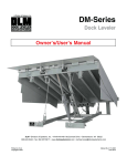
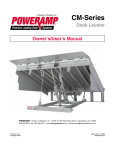
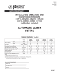
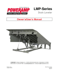
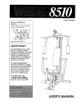
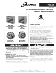
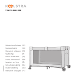
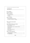
D8 - Distributor
l ubricate
Lubricate the distributor shaft sparingly (1-2
drops of oil)
D9 - Auxiliary unit belts
check/adjust
Applies to engines which do not have multi-tooth belts
Check belt tension.
It should be possible to press the middle of the belt
about 5-10 mm.
If necessary, adjust by changing the position of the
alternator.
3-track belt
Check belt tension with gauge 115 9660
Measure at A.
6-track belt
Check belt tension with special tools 999 5434
and 999 5436
Measure at B.
Remove the right-hand protecting cover for measuring
under B.
D10 - Auxiliary drive belt
grease the belt tensioner/replace belt
As of model year 1995, the belt tensioner is a maintenance-free unit
(Grease the belt tensioner every 45,000 km, fit a new belt every 90,000 km)
1
Remove the auxiliary drive belt
Use an articulated wrench with a 3/8" socket (1) in the
belt tensioner to loosen the belt.
On the 1995 model, use tool 999 5547 in the belt
tensioner's centre (2).
Lock the belt tensioner in its service setting with a lock
pin in the holes (3) when they are above one another.
Remove the belt.
2
Remove the belt tensioner
Undo the belt tensioner's two screws and remove the
tensioner.
3
Grease the automatic tensioner pulley
(not M/Y 1995)
Undo the pulley's centre screw and dismantle as in the
figure.
Apply grease, P/N 11 61 246-2 (50 g) or 11 61 247-0
(500 g) between the friction plate and cover, and in the
four holes used for the spring (marked by arrows).
Reassemble the belt tensioner. Torque-tighten the centre screw to 20 Nm.
Refit the belt tensioner
Torque-tighten to 20 Nm.
5
Fit the belt
New! A new belt every 90,000 km!
Loop the belt around the crankshaft.
Then loop it around the A/C compressor, idler pulley,
alternator and servo pump (the dotted line shows the
belt path if no A/C is fitted).
Tighten the belt tensioner using the articulated wrench
and fit the belt into place.
Check its operation.
D11 - Camshaft belt
replace
Special tool: 5284
1
Remove
• fan
• clamp for pre-heating hose under fan shroud (variant)
• fan shroud
Remove the drive belts and coolant pump pull ey
• undo the adjustment screws
• remove all the drive belts
• remove the pulley
Remove the upper timing gear casing
2
Adjust the camshaft - crankshaft acc. to the
markings
Rotate the crankshaft clockwise with the centre screw.
Position the camshaft so that the marking on the pulley
i s opposite the marking on the inner tooth belt cover and
the crankshaft marking is opposite 0 on the cover.
Engines with the distributor at the front edge of the
engine block: remove the distributor cap and check that
the rotor is aligned with the marking.
3
Remove the vibration damper
Remove the nut and washer from the belt tensioner.
Use counterhold 999 5284.
Secure it with the nut.
Remove the vibration damper screw. Remove counterhold 999 5284.
Check, adjust the 0-marking.
Remove the vibration damper.
4
Remove the lower timing gear casing.
5
Remove the camshaft belt
Undo the belt tensioner's nut about 1 revolution.
Pull out the pulley so that the pulley tensioner is compressed.
Tighten the nut once again.
Note! The pistons may strike the valves if the crankshaft or camshaft are rotated when the timing gear belt
i s removed.
Remove the camshaft belt.
6
Check the belt tensioner
Rotate the tension pulley and listen for abnormal noise
from the bearing.
Check that the contact surface with the belt is free from
scratches and rubber residue.
Check that the belt tensioner slides smoothly around its
guide pin, that the contact surface against the block is
clean.
After cleaning, lubricate with:
P/N 11 61 246 (50g) or 11 61 247 (500g).
7
Check the basic setting
Fit the new timing gear belt
I mportant! Do not rotate the crankshaft or camshaft,
or else the pistons may strike the valves.
• Align the tooth belt pulley with the marking.
• Thread the belt around the crankshaft and intermediate shaft. The two markings on the belt should be opposite the crankshaft marking.
• Tension the belt and thread it over the camshaft and
belt tensioner.
• Check that the belt is properly in place and that the
pulley markings are aligned with the engine markings.
Tension the timing belt
• Undo the belt tensioner nut approx. 1 revolution.
• The belt tensioner's spring will tension the belt.
• Retighten the nut.
8
Refit
- the lower timing gear casing
- the vibration damper
Check that the guide plate is correctly positioned.
I mportant! The vibration damper only fits in one
position. There is a lug on the crankshaft gear which
fits into the vibration damper.
Refit the crankshaft bolt and washer.
9
Tighten the vibration damper
Remove the nut and washer from the belt tensioner.
Use counterhold 999 5284. Fix it in position with the nut.
Tighten the crankshaft bolt:
Stage 1 60 Nm (6 kpm)
Stage 2 angle-tighten 60 (use protractor 999 5098)
Use counterhold 999 5284.
Fit the washer and nut on the belt tensioner.
Tighten the nut.
10
Refit
- the upper timing gear casing
- coolant pump pulley
- drive belts (loose)
- fan shroud
- pre-heating hose holder
- fan
Tension the drive belts
When correctly tensioned, the belt should be able to be
pressed down 5-10 mm using normal thumb pressure.
11
Start the engine and run it until the thermostat
opens. Switch off the engine.
12
Tension the camshaft belt
- Remove the rubber plug in the timing gear casing.
- Turn the engine over to TDC.
- Undo the belt tensioner nut approx. 1 revolution.
- The belt tensioner spring will tension the belt.
- Tighten the nut once again.
- Refit the plug in the timing gear casing.
Retighten belt tension after 15,000 km (see op.
D12)
Special tool: 5416, 998 8500
(Including replacement of balance shaft pulley
and greasing of tension pulley)
1
Remove:
- alternator drive belt
- drive belts for servo pump and A/C (if fitted)
- the three timing gear casings
- splash guard under the engine
.
2
Adjust camshafts - crankshaft according to
marking
Adjust engine to TDC for cylinder 1.
Check that the marking on the camshaft pulley is opposite the marking on the inner timing gear casing.
Check that the marking on the crankshaft's belt-guidance pulley is opposite the TDC marking on the engine
block.
3
Measure the belt tension
Wait 5 minutes after adjustment of the camshaft belt.
Place measurement instrument 998 8500 between the
output axle's belt pulley and the tensioner pulley.
Read the value.
Belt tension should be between 3.5 - 4.6 units.
If the correct value is not obtained, the tensioner must
be replaced.
4
Secure the camshaft gear
Use holder 999 5416.
Removing the camshaft belt
5
Remove the camshaft belt
Remove the tensioner's upper screw (M8).
Undo the lower screw (M10).
Rotate the tensioner until the screw is freed.
Remove the lower screw.
Remove the camshaft belt.
6
Check the tension and idler pulleys
Rotate the idler pulleys and listen for abnormal noise in
the bearings. Check that the pulley surfaces against the
belt are clean and smooth.
Check the tension pulley lever and the idler pulley
attachment.
Tension pulley lever, torque 40 Nm
I dler pulleys, torque 25 Nm
7
Greasing the bushing
Remove:
- the tension pulley's lever screw
- the tension pulley
- the socket behind the screw
Grease the surfaces of the lever's bushing, the screw
and socket with grease, P/N 11 61 246-2 (50 g) or 11
61 247-0 (500 g).
Refit:
- the socket
- the tension pulley
- the screw for the tension pulley; torque-tighten to 39
±5 Nm
Removal of the balance shaft belt
8
Remove the balance shaft belt's idler pulley
Check that the pulley surfaces and bearings are faultfree.
9
Undo the balance shaft belt tension pulley
Undo the lock screw.
10
Remove the balance shaft belt
Pull the belt off the tensioner pulley and balance shaft
pulley.
Pull the belt out under the crankshaft gear.
Check the tensioner pulley bearings and look for signs
of oil leakage at the shaft seals.
11
Check the balance shaft and crankshaft markings
Check the balance shaft markings to ensure that they
are opposite the marking on the inner timing gear casing.
Check that the crankshaft is opposite the TDC marking
on the engine block.
Fitting of balance shaft belt
12
The balance shaft belt's three markings
A. Balance shaft, right side (white dot).
B. Crankshaft lower marking (blue dot).
C. Balance shaft, left side (white dot).
A - B =18 teeth
B-C =34 teeth
13
Fit the balance shaft belt
Carefully insert the belt under the crankshaft gear.
Check that the belt's blue dot (marking B) is opposite
the TDC marking on the guide plate, on the lower
section of the crankshaft.
Thread the belt around the left (upper) balance shaft
so that the C-mark is opposite the balance shaft gear
marking.
Thread the belt on the right (lower) balance shaft, so
that the A-mark is opposite the balance shaft gear
marking.
Thread the belt around the tensioner pulley.
14
Check the balance shaft and crankshaft markings
Check that they are still correct.
15
Tighten the tensioner pulley
Tension the belt using a hexagonal key in the adjustment hole (1) of the pulley.
Rotate the crankshaft a few degrees to each side of the
TDC marking.
Position the crankshaft at TDC.
The pulley's adjustment hole should be just under the
3 o'clock position when the lock screw is tightened.
Tighten the lock screw (2) to 40 Nm. Use a hexagonal
key to counterhold the adjustment hole (1).
16
Check the belt tension
Use measuring instrument 998 8500.
Measure at the belt above the position of the removed
idler pulley. Belt tension should now be between 1-4
units.
Note! If belt tension is outside the above range, the
tension pulley should be loosened and step 15 should
be repeated.
Fitting the camshaft belt
17
Lock the tensioner element
Check that there is no visible leakage.
Press together the tensioner with tool 999 5456, Place
the tensioner in the tool and tighten the tool's centre
nut. Wait unit compression is completed and then insert
a lock pin (diam. 2 mm) in the piston.
18
Fit the camshaft belt
Place the belt's twin-stripe marking opposite the marking on the guide plate, on the upper side of the crankshaft.
Place the belt around the crankshaft gear and over the
tension pulley, and then over the right idler pulley.
Place the belt over the camshaft gears. The belt's two
single markings must match the camshaft gear markings.
Thread the belt around the left idler pulley and press
the belt over the tension pulley.
19
Fit the tensioner
Insert the tensioner screws.
Torque: M8 = 20 Nm, M 10 = 50 Nm.
Pull the lock pun out of the tensioner.
Remove holder 999 5416.
Rotate the crankshaft 2 revolutions and check that the
markings on the crankshaft and camshaft gears still
match.
20
Check/adjust balance shaft tension
Use gauge 998 8500. Measure on the belt above the
l ocation of the removed idler pulley.
Belt tension shall be 3.8±0.2 units at 20°C.
If tension is too low: Adjust by turning the tensioner
pulley clockwise.
Note! The tensioner pulley may only be turned clockwise.
Only small movements are required.
If tension is too high: Carry out steps 15-16.
Turn the crankshaft one revolution. Check/adjust the
newly set values.
21
I nstall:
- guide plate (check that it is in place)
- middle timing gear casing
- fan shroud
- tie strips for the heater hose
- radiator fan and pulley
- all the drive belts
22
Run the engine to operating temperature
Run the engine until the thermostat opens. Switch off
the engine.
Caution! Remember that timing gear casings (1) and (2)
have not yet been fitted at this point.
Check/adjust balance shaft belt tension
after thermostat opens
23
Check belt tension
Use gauge 999 8500
Place the gauge above the location of the removed idler
pulley.
Tension should be between 4.9 ± 0.2
units.
I f belt tension is correct, proceed to steps 27-29.
I f belt tension is too low, proceed to steps 24-26.
I f belt tension is too high, repeat steps 15-16, and adjust
as per steps 24-26.
24
Turn the crankshaft clockwise and read the gauge
Note! The tensioner pulley may only be rotated clockwise. Only small movements are required.
25
Turn the crankshaft clockwise one revolution
26
Check belt tension
Belt tension should now be within the prescribed range
4.9±0.2.
27
I nstall idler pulley
Ensure the pulley is properly seated
28
I nstall:
- the lower timing gear casing (2)
- the upper timing gear casing (1)
29
Test operation
Test-run the engine.
Special tool: 998 8500, 999 5456
(Including greasing the tension pulley)
1
Remove:
- the spark plug cover
- the two fuel pipe clamps
- lift up the expansion tank and place it above the engi ne
- the front timing gear cover
- the auxiliary unit belt
- the lower belt casing
2
Align the camshafts/crankshaft according to
the marking
Remove the right front wheel and undo the wheel arch
li ner somewhat.
Remove the vibration damper protecting plate.
Turn the crankshaft clockwise until the markings, camshaft gear and inner timing gear cover and the crankshaft, pulley/oil-pump housing match.
3
Check the belt tension
Wait 5 minutes after adjustment of the timing gear belt.
Place gauge 998 8500 between the output axle pulley
and the coolant pump.
Read the value with the help of a mirror; the gauge may
not be removed before the reading is completed.
Belt tension should be within
21 mm belt
23 mm belt, 4 valve
23 mm belt, 2 valve
3.5-4.6 units
2.5-4.0 units
2.7-4.2 units
I f the recommended value is not obtained, the tensioner must replaced.
4
Remove the camshaft belt
Remove the tensioner's upper screw.
Undo the lower screw.
Turn the tensioner so that the pulley rotates freely.
Remove:
- the lower screw.
- the tensioner.
- the upper timing gear casing.
- the camshaft belt.
5
Check the tensioner and idler pulleys
Rotate the pulleys and listen for abnormal noise from
the bearings. Check that the pulley contact surfaces
with the belts are clean and smooth.
Check that the tensioner pulley lever has not seized in
i ts bearing. Check the idler pulley attachment.
Tension pulley lever, torque 40 Nm.
I dler pulley, torque 25 Nm.
6
Greasing the bushing
Remove:
- the tension pulley lever's screw
- the tension pulley
- the socket behind the screw
Grease the surfaces of the lever's bushing, screw and
socket with grease, P/N 11 61 246-2 (50 g) or 11 61
247-0 (500 g).
Refit:
- the socket
- the tension pulley
- the tension pulley lever's screw; torque-tighten to 40
Nm.
7
Lock the tensioner
Check that there is no visible leakage.
Remove the plastic washer on the piston.
Compress the tensioner with tool 999 5456. Place the
tensioner in the tool and tighten the centre nut. Wait
until compression is complete and then insert a lock pin
(diam. 2 mm) in the piston.
Note! If there is any visible leakage or if there is no
resistance upon compression, or if compression is impossible, the tensioner must be replaced.
8
Fit the new camshaft belt
I nsert the tensioner screws.
Tighten to 25 Nm.
Thread the belt around the crankshaft and right idler
pulley.
Thread the belt over the camshaft gears.
Thread the belt around the coolant pump and press the
belt over the tension pulley.
9
Rotate the crankshaft through two revolutions
Pull out the lock pin from the tensioner.
Press hard or hit the belt with a plastic mallet
twice in the direction of arrow (1) and
twice in the direction of arrow (2).
Fit a new plastic washer on the piston.
Make sure that the washer is centred on the piston and
tensioner housing.
Note! Check that the correct side of the washer faces
upwards. See the illustration. The recessed side should
face up.
Fit the upper timing gear casing.
Rotate the crankshaft two revolutions and check that
the markings on the crankshaft and camshaft pulleys
match.
10
Refit:
- the two clamps for the fuel pipes
- the front timing gear cover
- the auxiliary unit belt
- the spark plug cover
- the expansion tank
- the lower belt casing
- the inner wheel arch liner
- the wheel
Check operation
Test-run the engine.
D12 - Camshaft belt/auxiliary unit belt
replace
Special tools
999 5434
,
999 5435
,
999 5436 ,
115 9660
1
Remove:
• right side protecting plate
• power steering pump cover
• auxiliary unit drive belts after the power steering
and/or alternator has/have been loosened.
• Remove the camshaft belt cover.
2
Remove the camshaft belt
Rotate the crankshaft so that cylinder no. 1 is at TDC
and the markings on the flywheel/bell housing and
camshaft belt cover/cam gear are opposite each other.
Remove the plug at the bottom right beside the oil
dipstick and insert an 8 mm lock pin in the hole in the
crankcase.
Check that the crankshaft cannot be rotated.
Remove the crankshaft pulley and vibration damper.
Remove the belt cover and make a mark on the edge
opposite the mark on the camshaft gear. Undo the belt
tensioner. Remove the belt. Begin at the tensioner.
3
Fit the camshaft belt
Check that the lock pin is in place. Place the belt so that
the mark is opposite the marks on the crankshaft and
camshaft gear.
Observe the following when fitting:
the belt's direction of movement (see the arrow);
the sequence in which the belt is to be fitted to the gears
(see fig.)
4
Adjust the camshaft belt
Tension the belt with the help of an M6 screw.
Use special tools 999 5434 and 5435.
Correct tension: 7.5 mm (cold belt).
Tighten the tensioner's lock nut.
Tightening torque: 50 Nm.
5
Check that the belt is correctly fitted
Remove the special tool.
Remove the lock pin.
Turn the crankshaft two full revolutions in the correct
direction of rotation.
Rotate the crankshaft to the TDC position (insert the
l ock pin) and check that the mark on the camshaft gear
i s opposite the mark on the edge of the belt cover.
Remove the lock pin and refit the plug.
6
Check camshaft belt tension
Use special tools 999 5434 and 5435 to check the
tension: 7.5 mm.
Remove the tensioner screw.
7
Fit:
• camshaft belt cover
• crankshaft pulley
• auxiliary unit drive belt
• drive belt for power steering and air conditioning (where fitted).
Check/adjust the auxiliary unit belts: see inspection
point D9.
Fit a new timing gear belt/and Poly V-belt
Special tools 999 5006, 999 5115, 999 5383,
999 5434, 999 5506
Remove:
- the lower cover plate for the Poly V-belt
- Poly V-belt from the alternator/coolant pump
Fit the lifting eyelet and its lift hooks.
Place a flannel under the fuel return pipe.
Remove fuel return pipe at the fuel pump's pipe and
remove it from the lifting eyelet beside the timing gear
end.
Remove the rubber gaiter.
Remove the screw at the left front wing (A).
Place lifting eyelet 999 5006 above the engine and
i nsert hook 999 5115 into the eyelet.
Place support unit 999 5383 and lifting eyelet 999 5115
i n the eyelet.
Lower the engine mounting at the timing gear.
Remove the three screws (1) and nut (2) and remove
the mounting.
Remove the fuel filter from the housing bracket.
Remove the two nuts.
Remove the timing gear housings.
Remove the three screws (3) and dismantle the timing
cover from the fuel pump's gear. Remove the four
screws (5) and dismantle the upper timing gear cover.
Remove the timing belt
Rotate the crankshaft clockwise until cyl. no. 1 (flywheel
side) is above the TDC injection point so that the following markings match:
- flywheel - bell housing
- rear protecting plate - camshaft gear
Etch a mark on the injection pump's mounting bracket
opposite the mark on the injection pump's drive gear.
Remove the plug from the threaded hole to the right of
the oil dipstick. Insert an 8 mm thick drill bit through the
hole.
Check that the drill locks the crankshaft.
Remove the crankshaft pulley.
Undo the tensioner pulley.
Remove the drive belt.
Clean and check the drive gears.
Fit the timing belt.
Check that the drill bit in the crankshaft has not shifted.
Fit the timing belt.
The markings on the belt should match the marks on
the crankshaft/injection pump gear.
Note! Observe the following when fitting the belt:
- the belt's direction of rotation (arrows on the belt)
- the sequence in which the belt is to be fitted over the
various gears (follow the numbers in the figure).
- the tension pulley must be completely non-tensioned
so as to avoid damaging the belt.
Adjusting the timing belt
Tighten an M6 screw to adjust the position of the tension pulley.
Apply special tool 999 5506 to the belt and the tension
pulley.
Slide the 0-ring on gauge 999 5434 below the graded
scale (1).
Place gauge 999 5434 in the hole in 999 5506 and press
the tool as in the illustration 2.
The depth of pressure can be felt with the thumb.
The correct pressure is obtained when the measuring
needle is at the same height as the top of the gauge.
Carefully withdraw gauge 999 5506 and read the belt
tension (in mm).
Adjust belt tension correctly using the M6 screw. Reference value for checking and adjusting
(cold engine): 7.5 mm.
Tighten the tension pulley's lock nut to 50 Nm.
Check that the marks on the timing belt match the marks
on
- crankshaft l injection pump gear
- crankshaft gear
Fit the crankshaft pulley
Fit the crankshaft pulley.
Clean the centre screw.
Apply locking fluid and tighten the screw to 95 Nm.
Check that the crankshaft pulley is correctly fitted.
Remove tool 999 5434. Remove the drill bit.
Rotate the crankshaft two full revolutions (clockwise).
Stop in the TDC position and reinsert the drill bit.
Check that the marks on the timing gear cover and
injection pump mounting bracket match the marks on
the camshaft/injection pump's gears.
Check belt tension.
Remove the M6 screw
Check-tighten belt tension and adjust if necessary
(see the section on adjusting the timing belt on the
previous page)
Check/adjust injection pump.
Fit the gauge to the injection pump.
I f necessary, remove 6 mm of material from the gauge
999 5382 (see the figure)
Remove the drill bit and rotate the crankshaft 3/4 revol ution clockwise.
Fit gauge 999 5382:
- remove the plug (B) and insert the pin (2), which bel ongs to the special tool.
- fit and tighten the holder (3).
- fit the dial gauge (4) and insert it at least 0.2 mm.
Tighten the gauge and reset it to zero.
Check/adjust injection.
Rotate the crankshaft clockwise until the needle on the
gauge shows 5.00.
Press the drill bit in and rotate the crankshaft clockwise
until the drill slips into the recess in the crankshaft.
Read the gauge.
The reference value is found on the pump's inspection
arm.
Tolerance 0.02 mm.
I f the correct value is not obtained, undo the pump
gear's three screws (5); the pump's drive shaft (6) is
rotated until the correct value is appears on the dial.
Tighten the three screws to 20 Nm.
Check the setting once more.
Remove the gauge.
Remove tool 999 5382 together with the dial and pin.
Refit the plug with a new gasket. Tighten to 20 Nm.
Fit the oil filler cap.
Fit the timing covers.
Fit the upper timing cover and the four screws.
Fit the fuel pump's gear casing and the three screws.
Tighten all the screws.
Tightening torque: 9 Nm.
Refit the engine mounting.
Fit the mounting.
Fit and tighten the three screws.
Tightening torque: 50 Nm.
Fit and tighten the nut.
Tightening torque: 50 Nm.
Remove lifting eyelet 999 5006 and 999 5383 together
with the hooks 999 5115.
Check the fitting and adjust if necessary.
Connect the fuel pump's return pipe.
Fit:
- the rubber ring in the lifting eyelet
- the return pipe through the lifting eyelet
- a new clamp on the return pipe
Connect the return pipe to the fuel pump's pipe and
tighten the clamp.
Bleed the fuel system.
Place a container under the pump. Connect a hose to
the bleeder screw (3) and let it hang down into the
container.
Open the bleeder screw.
Use the filter's manual pump build up pressure until
clean fuel appears via the bleeder screw.
Shut the bleeder screw and remove the hose.
Pump a few more times until a slight resistance is felt.
Fit the Poly V-belt on the alternator/coolant pump.
Check/adjust the drive belt (Poly V-belt)
Fit tools 999 5434 and 999 5436 to the belt.
Thread the gauge's 0-ring below the graded scale (4).
Fit the gauge and press it as far in as shown in the figure
(5).
The depth of this pressure can be felt with the thumb.
The correct length is obtained when the needle is flush
with the top of the gauge.
Carefully remove the gauge and read the belt tension
(6).
Fit:
- the lower cover plate and tighten to 9 Nm
- side protector
Fit:
- fuel filter
- the two nuts and tighten them
- Start and check
Special tool: 998 8500
Removal of auxiliary unit belt incl.
greasing of belt tensioner
As of model year 1994, the belt tensioner is maintenance-free
1
Remove the auxiliary unit belt
Remove the belt. Use an articulated wrench with a 3/8"
socket (1) to loosen the belt.
As of M/Y 1994, use tool 999 5547 in the belt tensioner's
centre (2).
Lock the belt tensioner in the service setting by inserting a lock pin in the holes (3) when they are above each
other.
Remove the belt.
2
Remove the belt tensioner
Undo the belt tensioner's two screws and remove the
tensioner.
3
Grease the automatic tensioner pulley
Undo the tensioner's centre screw and dismantle as in
the figure.
Apply grease P/N 11 61 246-2 (50 g) or 11 61 247-0
(500 g) between the friction plate and cover, and in the
four holes used for the spring (marked by arrows).
Reassemble the belt tensioner. Torque-tighten the belt
tensioner. Torque-tighten the centre screw to 20 Nm.
4
Refit the belt tensioner
Torque-tighten to 20 Nm.
Replacing the camshaft felt incl.
greasing the tension pulley
5
Remove:
- the front timing gear casing
- the splash guard under the engine
- the vibration damper shield
- ignition cable cover
6
Set the camshaft/crankshaft acc. to the markings
Rotate the crankshaft clockwise until the markings on
the camshaft pulley and inner timing gear cover and the
markings on the crankshaft pulley/oil pump housing
match.
Remove the upper timing gear cover.
7
Measure belt tension
Wait for 5 minutes after adjustment of the camshaft belt.
Place gauge 998 8500 between the output shaft pulley
and the coolant pump.
Read the value.
Belt tension should be between:
21 mm belt
3.5 - 4.6 units
23 mm belt
3.0 - 4.0 units
28 mm belt
2.5 - 3.5 units
I f the specified value is not obtained, the tensioner unit
must be replaced.
Remove the camshaft belt
Loosen and remove the tension unit's upper screw.
Undo the lower screw.
Rotate the tension unit so that the screw is released.
Remove the lower screw.
Remove the tension unit.
Remove the camshaft belt.
Do not rotate the camshafts or crankshaft when the
ti ming gear belt has been removed.
9
Check the tensioner and idler pulleys
Rotate the pulleys and listen for abnormal noise from
the bearings. Check that the pulley surfaces facing the
belt are clean and smooth.
Check the tension pulley lever and the idler pulley's
attachment. Tension pulley lever, torque 40 Nm.
I dler pulley, torque 25 Nm.
10
Grease the bushing
Remove:
- the tension pulley lever's screw
- the tension pulley
- the socket behind the screw
Grease the surfaces of the lever's bushing, screw and
socket with grease, P/N 11 61 246-2 (50 g) or 11 61
247-0 (500 g).
Fit:
- the socket
- the tension pulley
- the tension pulley lever's screw; torque-tighten to
39±5 Nm.
11
Lock the tensioner
Check that there is no visible leakage.
Compress the tensioner with tool 999 5456. Place the
tension unit in the tool and screw the tool's centre nut
to the end. Wait until compression is complete and
i nsert a lock pin (0 2 mm) in the piston.
Note! If there is any visible leakage or if no resistance
is felt during compression, or if compression is impossible, the tensioner must be replaced.
12
Fit the camshaft belt
Thread the belt around the crankshaft and right idler
pulley.
Thread the belt over the camshaft pulleys.
Thread the belt around the coolant pump and press it
over the tensioning pulley.
13
Fit the tensioner
Fit the tensioner's screws, torque 25 Nm.
Pull out the lock pin from the tensioner.
Press firmly or hit the belt with a rubber mallet
twice in the direction of arrow (1) and
twice in the direction of arrow (2).
Fit the upper timing gear cover.
Fit the upper timing gear cover.
Rotate the crankshaft two revolutions and check that
the markings on the crankshaft and camshaft pulleys
match.
14
Fit:
- ignition cable cover
- front timing gear casing
- vibration damper shield
- splash-guard under the engine
Perform a function test
Test run the engine.
Fit the auxiliary unit belt
Note! New belt every 90,000 km!
Thread the belt around the crankshaft.
Then around the A/C compressor, idler pulley, alternator and servo pump.
Tighten the belt tensioner with the articulated wrench
and position the belt.
Check its operation.