1
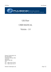
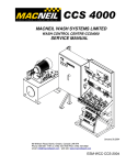
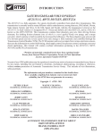
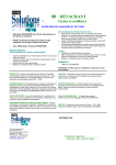
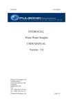
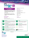
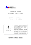
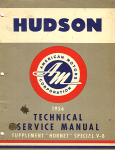
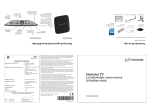
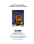
"2011” SEMINAR INFORMATION
8
MERCEDES BENZ 722.9
PRELIMINARY INFORMATION
Mercedes Benz has produced a new 5th generation
electronically controlled gearbox with seven forward
and two reverse speeds.
Vehicle Application/Transmission Designation
The W7A 700 is the only model size 722.9 being
produced at the time of this written material, a smaller
model the W7A 400 will be introduced at a later time.
This transmission is referred to as:
NAG 2 (Neues Automatische Getriebe 2)
New Automatic Gearbox 2 or 7G- Tronic
Vehicle Applications:
Select non 4MATIC (2WD) MY 2004 vehicles
w/M113 engine.
S340, S/CL/E/SL500
Optional:
SLK (R171-09/04)
Standard Equipment:
CLS 350 (late 2004)
E350 (late 2004)
M Class (W164-2005)
R Class (W251-2005)
G Class (X164-2006)
End of production models that will unlikely receive
the 722.9 would be W163, R170 & V463.
722.9 for W164/W251/X164 will be equipped with
shift by wire (no shifter rod or cable). An electronic
control module on the left rear side of the
transmission just above the pan rail which operates a
shift control valve and its position is monitored by a
position sensor.
The 722.6 (NAG 1 or V) will continue production
until approximately MY 2012 and installed in:
4 cyl models
Maybach
M275 vehicles
some select manufacturer’s contract vehicles
Fluid Type
Newly developed suggested use “only” transmission
fluid, referred to as “ATF 3353 with higher friction
consistency, thermal stability and temperature rating.
Can also be used on previous model 722.3/.4/.5/.6
transmissions. No scheduled maintenance required
(fill for life) and available at Shell & Fuchs Europe oil
suppliers in 1 liter bottles under Mercedes Benz part
number A001 989 45 03 10.
Electronic Control Components
The Transmission Control Module (Y3/8n4) which is
Copyright © 2011 ATSG
flash capable, along with the following components:
Eight Solenoids:
Working Pressure Control Solenoid
(Y3/8y1)
K1Clutch Solenoid (Y3/8y2)
K2 Clutch Solenoid (Y3/8y3)
K3 Clutch Solenoid (Y3/8y4)
B1Brake Clutch Solenoid (Y3/8y5)
B2 Brake Clutch Solenoid (Y3/8y6)
B3 Brake Clutch Solenoid (Y3/8y7)
Torque Converter Lock Up Solenoid
(Y3/8y8)
Two Oil Floats
Oil Control Float 1 (31)
Oil Control Float 2 (32)
Three Speed Sensors
Turbine RPM Sensor (Y3/8n1)
Internal RPM Sensor (Y3/8n2)
Output RPM Sensor (Y3/8n3)
Selection Range Sensor (Y3/8s1)
are all integrated into the valve body assembly.
Shift Strategy
The shift strategy improvements include:
! Shorter computer reaction time by 0.1 second
! Downshifts shortened by up to 0.2 seconds
! Coasting downshifts shortened by 0.4/2.5 seconds
! 37-47 MPH acceleration times shortened by 2328% (model dependant)
! Fuel consumption reduced by up to 4%
! Noise levels reduced, due to lower engine speed in
5th, 6th & 7th gear at constant vehicle speed
! Flexible adaptation to vehicle and engine
Variable Shift Programing
Two basic shift programs can be varied by customer
(same as 722.6) using the S/C button on the
Electronic Shifter Module (ESM)
“S”( Sport)
1st gear starts
Normal shift points
Reverse gear 1 (-3.416:1)
“C” (Comfort)
2nd gear starts
Earlier up-shifts and later downshifts
Reverse gear 2 (-2.231:1)
Note: Transmission will start in first gear if any of
the following conditions apply:
1st gear is manually selected
3/4 to full throttle acceleration from start
Cold engine temp (pre catalytic warm up)
Automatic Transmission Service Group
"2011” SEMINAR INFORMATION
9
MERCEDES BENZ 722.9
PRELIMINARY INFORMATION
Shift Optimal Gear (SOG)
Shift into Optimal Gear software as known in previous
models .
Up shifts and downshifts based on driving style and
engine load (similar to 722.6)
Shift interlock controlled by Electronic Shifter
Module (ESM) same as previous models
Emergency function/Limp-home mode:
There are a variety of failsafe modes; if a solenoid is
defective the gear affected is blocked (example
solenoid Y3/8y7-B3 clutch is defective: no 1st, 7th or
Reverse in “S” mode) If hydraulic fault prevents a gear
from engaging then the previous gear will be applied.
If the computer defaults while driving, all solenoids
will be turned off. Solenoids that are normally open
will allow full pressure to selected clutches and the
transmission will be in 6th gear. After shifting to “P”
oil pressure from K2 solenoid is redirected to B2/BR
solenoid via emergency operation valves and the
transmission will now achieve 2nd in “D” and
Reverse.
Gear Ratio
The gear ratios are achieved with four multi-disc
brakes and three multi-disc clutches, no free wheels
units (sprags)
There are three planetary gear sets:
Two simple
One Ravigneaux
Torque Converter (same used in some 722.6)
Torque converter operates in open or slip mode in all
seven forward gears.
Lock up converter is never fully locked.
Converter is open in 1st & 2nd gear if throttle and
output shaft speed are in “Zone A”
Converter is in slip-control in all 7 forward gear if
throttle and output shaft speed are in “Zone B”. Oil
feed pressure to the converter is varied depending on
the amount of desired slip.
Open: High flow
Slip Control: Lower flow
Lock up clutch will turn off and transmission will shift
to a lower gear at oil temperatures of 140C or higher.
Holds = 4 liters of fluid
Incorporates damper springs integral to lock up clutch
to reduce vibration.
Copyright © 2011 ATSG
Vehicle Towing
If vehicle must be towed it should be transported by
use of a flat bed trailer type of tow truck.
Alternate towing with vehicle drive axle lifted.
If either fore mentioned options are not available a tow
bar (preferred) will suffice under the following
conditions/limitations:
1. Turn key to position 2
2. Selector lever to”N” position
3. Max. towing speed 31 mph
4. Max. towing distance 31 miles
Note: If towing distance or speed exceeds pre
mentioned values damage may occur to transmission.
Clutch Clearances no. of disc 722.9 722.93
(mm) (mm)
B1 Brake
3
2.0-2.4
4
2.2-2.6 2.2-2.6
5
2.3-2.7
B2 Brake (internal tooth) 4
1.7-2.1 1.7-2.1
5
1.8-2.2 1.8-2.2
(external tooth) 5
1.7-2.1 1.7-2.1
6
1.8-2.2 1.8-2.2
B3 Brake
3
2.0-2.4 2.0-2.4
4
2.2-2.6 2.2-2.6
5
2.3-2.7 2.3-2.7
Br Brake
N/A
1.0-1.4 1.0-1.4
K1 Clutch
3
2.0-2.4
4
2.2-2.6
5
2.4-2.8 2.4-2.8
6
2.4-2.8
K2 Clutch
3
1.7-2.1
4
1.9-2.3
5
2.1-2.5
6
2.2-2.6 1.9-2.3
7
2.0-2.4
8
2.1-2.5
K3 Clutch
3
2.4-2.8
4
2.2-2.6
5
2.4-2.8
All clutch clearances are measured between the
Flange and retainer ring, while applying the amount of
hand pressure listed below.
B1 = N 600
B2 = N 1000 B3 = N 600
BR = N/A
K1 = N 800
K2 = N1200
K3 = N 600
Note: B2 Brake multi disc clutches use single sided
plates at this point in time other clutch members may
use single sided plates at a future date.
Automatic Transmission Service Group
"2011” SEMINAR INFORMATION
12
MERCEDES BENZ 722.9
PRELIMINARY INFORMATION
B3 Feed Port
K1 (Y3/8y2)
B1 (Y3/8y5)
N.C./N.V.
Green Top
N.O./N.A.
Black Top
B3 (Y3/8y7) K3 (Y3/8y4)
N.C./N.V.
Green Top
N.O./N.A.
Black Top
Y3/8n3
Y3/8n4
Y3/8n1
Y3/8n2
Y3/8s1
TCC (Y3/8y8)
PCS (Y3/8y1)
K2 (Y3/8y3)
B2/BR (Y3/8y6)
N.C./N.V.
Green Top
N.O./N.A.
Black Top
N.O./N.A.
Black Top
N.C./N.V.
Green Top
Y3/8n1 = Input speed sensor (front) - Reads Input Shaft Speed
Y3/8n2 = Middle speed sensor (center) - Reads Ravigneaux Carrier/Rear Internal Ring Gear Speed
Y3/8n3 = Output speed sensor (rear) - Reads Output Shaft Speed
Y3/8n4 = Electrohydraulic Control Module (TCM) (w/internal transmission fluid temp sensor)
Y3/8y1 = Working Pressure - (Normally Open/Normally Applied (Solenoid off = High Pressure)
Y3/8y2 = K1 Clutch - Normally Closed/Normally Vented (Solenoid off = No Pressure)
Y3/8y3 = K2 Clutch - (Normally Open/Normally Applied (Solenoid off = High Pressure)
Y3/8y4 = K3 Clutch - (Normally Open/Normally Applied (Solenoid off = High Pressure)
Y3/8y5 = B1 Brake - (Normally Open/Normally Applied (Solenoid off = High Pressure)
Y3/8y6 = B2/BR Brake - Normally Closed.Normally Vented (Solenoid off = No Pressure)
Y3/8y7 = B3 Brake - Normally Closed.Normally Vented (Solenoid off = No Pressure)
Y3/8y8 = Lock-Up - Normally Closed.Normally Vented (Solenoid off = No Pressure)
Y3/8s1 = Range sensor
Note: Normally Open/Normally Applied solenoids are used when Limp Mode strategy has been initiated
when all solenoids are turned off
Copyright © 2011 ATSG
Automatic Transmission Service Group
"2011” SEMINAR INFORMATION
13
MERCEDES BENZ 722.9
HALL AFFECT SPEED SENSORS
Magnet Rings are covered by
Non Ferrous Metal
Magnet Ring Integral to the
Ravigneaux Carrier which
spins around the outside
of the K2 Clutch Drum
Park Pawl
Gear
Magnet Ring Integral to the
K2 Clutch Drum
Input (Turbine) Shaft
The back Ravigneaux Ring Gear
is integral to the K2 Clutch Drum
Y3/8n1
Y3/8n2
Y3/8n3
Front speed sensor (Y3/8n1): monitors Input (Turbine) Shaft and back Ravigneaux Ring Gear speed.
Center speed sensor (Y3/8n2): monitors Ravigneaux carrier and rear Ring Gear speed.
Rear speed sensor (Y3/8n3): monitors Output Shaft speed from exciter ring on the Park Pawl gear
Note: Magnets are molded in a plastic ring and secured inside Non Ferrous flanges
Copyright © 2011 ATSG
Automatic Transmission Service Group
"2011” SEMINAR INFORMATION
14
MERCEDES BENZ 722.9
RANGE SENSOR & ELECTRICAL CONNECTOR
5 PIN CONNECTOR
(2 round o-rings & 1 square o-ring)
3
2
1
FLUID LEVEL
FLOAT
4
5
ELECTRICAL
CONNECTOR
1: CAN C High
2: CAN C Low
3: Diagnostic Line
4: Circuit 87 (relay & fuse depending on model)
5: Circuit 31
Y3/8n4
Y3/8s1
FLUID LEVEL
FLOAT
RANGE SENSOR
The Range sensor (Y3/8s1) is integral to the TCM conductor plate and is not replaced separately. A magnet
located on the Manual Valve signals its position through sensor pick ups referred to as: Permanent Magnetic
Linear Contact-less Displacement Sensor (PLCD). If this is a failsafe item should it become faulty or the
signal is not learned.
Fluid Level Floats (2):To prevent oil foaming from gears running in fluid. The front one was added due to
transmission extended length (41mm) causing oil to slosh during hard forward stops.
Copyright © 2011 ATSG
Automatic Transmission Service Group
"2011" SEMINAR INFORMATION
16
MERCEDES BENZ 722.9
SOLENOID APPLICATION
SOLENOID APPLICATION & SOLENOID FUNCTION
CLUTCH/
BRAKE
SOLENOID
Gear Ratio
B1
B2/BR*
B3
K1
K2
K3
Y3/8y5
N.O. (M)
Y3/8y6
N.C. (M)
Y3/8y7
N.C. (M)
Y3/8y2
N.C. (M)
Y3/8y3
N.O. (M)
Y3/8y4
N.O. (M)
Normally
Applied
Normally
Vented
Normally
Vented
Normally
Vented
Normally
Applied
Normally
Applied
Current Psi from
Current Psi from
Current Psi from
Current Psi from
Current Psi from
Current Psi from
to Solenoid Solenoid to Solenoid Solenoid to Solenoid Solenoid to Solenoid Solenoid to Solenoid Solenoid to Solenoid Solenoid
High
Low
Varying Varying Varying Varying
Low
Low
High
Low
Varying Varying
Low
Low
High
Low
Varying Varying
High
Low
Varying Varying
1
4.377
2
2.859 Varying Varying Varying Varying
Low
Low
3
1.921
High
Low
Varying Varying
Low
Low
Varying Varying
4
1.368
High
Low
Varying Varying
Low
Low
Varying Varying Varying Varying
5
1.000
High
Low
Low
Low
Low
Low
Varying Varying Varying Varying Varying Varying
6
0.820 Varying Varying Low
Low
Low
Low
7
0.728
N (1)
N (2)
R (1) -3.416
High
Low
Low
Low
Varying Varying Varying Varying
High
Low
Low
Low
Varying Varying
Low
Low
Varying Varying Varying Varying
High
Low
Low
Low
Varying Varying
Low
Low
High
Low
Varying Varying
Low
Low
Low
Low
High
Low
Varying Varying
(BR)
(BR) Varying Varying
Low
Low
High
Low
Varying Varying
Low
Low
High
Low
Varying Varying
Varying Varying
High
Low
Low
Low
Varying Varying
(BR) (BR)
R (2) -2.231 Varying Varying Varying Varying Low
Low
N.O. (M) = Mercedes nomenclature for Normally Open. This refers to the Solenoid feed connection to Solenoid
output pressure. To Simplify, Normally Open = Solenoid feed is connected to Solenoid output when the
Solenoid is OFF, ATSG refers to that as Normally Applied.
N.C. (M) = Mercedes nomenclature for Normally Closed. This refers to the Solenoid feed connection to
Solenoid output pressure. To Simplify, Normally Closed = Solenoid feed is blocked to Solenoid output when the
Solenoid is OFF, ATSG refers to that as Normally Vented.
*B2 & BR share the same solenoid the oil is directed to a different clutch members by the selector shift valve
Failsafe while driving all solenoids will be turned off, transmission will shift to 6th gear.
After engaging Park then Drive: only 2nd & Reverse gear are available.
Copyright © 2011 ATSG
Automatic Transmission Service Group
"2011” SEMINAR INFORMATION
17
MERCEDES BENZ 722.9
CLUTCH POSITION & APPLICATION
B1
B3
K2
BR
K3
B2
K1
NO FREEWHEEL (SPRAG)
Gear
Gear Ratio
W7A 700
1
4.377
2
2.859
3
1.921
X
X
4
1.368
X
X
X
5
1.000
X
X
X
6
0.820
X
X
7
0.728
X
X
B1
X
B2
B3
X
X
K1
-3.416
R (2)
-2.231
K3
X
X
X
X
X
X
X
X
X
R (1)
K2
X
N (1)
(1) S Mode
BR
X
X
X
X
(2) C Mode (X) Applied
Copyright © 2011 ATSG
Automatic Transmission Service Group
"2011” SEMINAR INFORMATION
18
MERCEDES BENZ 722.9
SHIFT SEQUENCES
B1
B2
B3
K1
K2
K3
X
X
X
X
X
X
X
X
X
7th Gear
6th Gear
X
5th Gear
4th Gear
X
X
3rd Gear
X
X
2nd Gear
1st Gear
X
X
X
X
Release B3
X
X
X
7
6
Apply K1
5
Release K2
4
Apply B2
3
Release K1
Apply B3
Apply B2
2
1
The 722.9 transmission has Sequential shifting (clutch on clutch) in addition to providing a down shift
strategy that allows the transmission to skip gears during down shifts as long as one clutch member is
released as another is applied.
Copyright © 2011 ATSG
Automatic Transmission Service Group
"2011” SEMINAR INFORMATION
19
MERCEDES BENZ 722.9
POWER FLOW
B1
B3
K2
BR
K3
B2
K1
Gear
Ravigneaux
Center Planetary
(Rear Internal Ring Gear)
(Output Shaft)
Rear Planetary
First
2.25:1 Reduction
Reduction
Reduction
Second
1.50:1 Reduction
Reduction
Reduction
Third
1:1
Reduction
Reduction
Fourth
1:1
Reduction
---------
Fifth
1:1
1:1
1:1
Sixth
1.50:1 Reduction
Overdriven
Overdriven
Seventh
2.25:1 Reduction
Overdriven
Overdriven
* The Ravigneaux gear set drives the rear internal ring gear. For every 1 revolution of the ring
gear both the rear and middle sun gears are forced to rotate 2.5 times (when the K3 clutch is applied).
The rear carrier and middle internal ring gear are being driven at input speed via the K2 clutch.
The difference between the speed of the middle sun gear and the middle internal ring gear causes
the middle carrier and output shaft to rotate at an overdrive speed of 0.820:1 in 6th and 0.728:1 in 7th.
Automatic Transmission Service Group
"2011” SEMINAR INFORMATION
20
MERCEDES BENZ 722.9
POWER FLOW
Power Flow 1st Gear
B1
B3
BR
8
K2
1
16
2
B2
5
K3
9
12
4
6
3
K1
15
18
14
11
7
Input Torque
10
13
17
Input Shaft
Output Shaft
The Ravigneaux Planet Small Ring Gear (5) is driven by the Input Shaft. The Long Planet Gears (15) drive the
Short Planet Gears (16) to rotate inside the Large Ring Gear (8) held by the B3 Brake Clutch. An increase in
torque and reduced rpm is transmitted to the Dual Planet Carrier (6). The Single Rear Planet Ring Gear (9)
rotates at the same speed as it is mechanically connected to the Dual Planet Carrier. The Planet Gears (18)
rotate around Sun Gear (11) held by the K3 Clutch and rotate Planet Carrier (10). The Single Front Planet Ring
Gear (12) is mechanically connected to the Planet Carrier (10) and rotates at the same speed. Planetary Gears
(17) rotate around Sun Gear (14) which is held by the B2 Brake Clutch and transfers the increased torque and
reduced rotational speed to the Output Shaft through Planet Carrier (13). The Output Shaft rotates with
reduced input speed in the direction of engine rotation at a ratio of 4.377.
Front Single Planet Gear Set:
Planetary Gears (17)
Ring Gear (12)
Planet Carrier (13)
Sun Gear (14)
Ravigneaux gear set:
Short Planet Gears (16)
Long Planet Gears (15)
Small Ring Gear (5)
Dual Planet Carrier (6)
Sun Gear (7)
Large Ring Gear (8)
1 Torque Converter Lockup Clutch
2 Turbine Wheel
3 Stator
4 Impeller
5 Small Internal Geared Wheel
6 Dual Planet Carrier
7 Sun Gear
8 Large Internal Geared Wheel
9 Internal Geared Wheel
10 Single Planetary Carrier
11 Sun Gear
12 Internal Geared Wheel
Rear Single Planet Gear Set:
Planetary Gears (18)
Ring Gear (9)
Planet Carrier (10)
Sun Gear (11)
13 Single Planetary Carrier
14 Sun Gear
15 Long Planet gears
16 Planet Gears
17 Planet Gears
BR Multi-Disc Brake (BR)
B1 Multi-Disc Brake (B1)
B2 Multi-Disc Brake (B2)
B3 Multi-Disc Brake (B3)
K1 Multi-Disc Clutch (K1)
K2 Multi-Disc Clutch (K2)
K3 Multi-Disc Clutch (K3)
Copyright © 2011 ATSG
Automatic Transmission Service Group
"2011” SEMINAR INFORMATION
21
MERCEDES BENZ 722.9
POWER FLOW
Power Flow 2nd Gear
B1
B3
BR
8
K2
1
16
2
B2
5
K3
9
12
4
6
3
K1
15
18
14
11
7
Input Torque
10
13
17
Input Shaft
Output Shaft
The Ravigneaux Planet Small Ring Gear (5) is driven by the Input Shaft. The Long Planet Gears (15) rotate
around Sun Gear (7) which is held by the B1 Brake Clutch. An increase in torque and reduced rpm is
transmitted to the Dual Planet Carrier (6). The Single Rear Planet Ring Gear (9) rotates at the same speed as it
is mechanically connected to the Dual Planet Carrier. The Planet Gears (18) rotate around Sun Gear (11) held
by the K3 Clutch and rotate Planet Carrier (10). The Single Front Planet Ring Gear (12) is connected
mechanically to the Planet Carrier (10) and rotates at the same speed. Planetary Gears (17) rotate around Sun
Gear (14) which is held by the B2 Brake Clutch and transfers the increased torque and reduced rotational speed
to the Output Shaft through Planet Carrier (13). The Output Shaft rotates with reduced input speed in the
direction of engine rotation at a ratio of 2.859.
Front Single Planet Gear Set:
Planetary Gears (17)
Ring Gear (12)
Planet Carrier (13)
Sun Gear (14)
Ravigneaux gear set:
Short Planet Gears (16)
Long Planet Gears (15)
Small Ring Gear (5)
Dual Planet Carrier (6)
Sun Gear (7)
Large Ring Gear (8)
1 Torque Converter Lockup Clutch
2 Turbine Wheel
3 Stator
4 Impeller
5 Small Internal Geared Wheel
6 Dual Planet Carrier
7 Sun Gear
8 Large Internal Geared Wheel
9 Internal Geared Wheel
10 Single Planetary Carrier
11 Sun Gear
12 Internal Geared Wheel
Rear Single Planet Gear Set:
Planetary Gears (18)
Ring Gear (9)
Planet Carrier (10)
Sun Gear (11)
13 Single Planetary Carrier
14 Sun Gear
15 Long Planet gears
16 Planet Gears
17 Planet Gears
BR Multi-Disc Brake (BR)
B1 Multi-Disc Brake (B1)
B2 Multi-Disc Brake (B2)
B3 Multi-Disc Brake (B3)
K1 Multi-Disc Clutch (K1)
K2 Multi-Disc Clutch (K2)
K3 Multi-Disc Clutch (K3)
Copyright © 2011 ATSG
Automatic Transmission Service Group
"2011” SEMINAR INFORMATION
22
MERCEDES BENZ 722.9
POWER FLOW
Power Flow 3rd Gear
B1
B3
BR
8
K2
1
16
2
B2
5
K3
9
12
4
6
3
K1
15
18
14
11
7
Input Torque
10
13
17
Input Shaft
Output Shaft
With the K1 Clutch engaged, the Ravigneaux Planetary Gear set components (5, 6, 7, 8, 15 & 16) are locked
together and send Input Torque and Input Speed unchanged to Ring Gear (9).The Single Rear Planet Ring
Gear (9) drives the Planet Gears (18) to rotate around Sun Gear (11) held by the K3 Clutch and rotate Planet
Carrier (10). The Single Front Planet Ring Gear (12) is connected mechanically to the Planet Carrier (10) and
rotates at the same speed. Planetary Gears (17) rotate around Sun Gear (14) which is held by the B2 Brake
Clutch and transfers the increased torque and reduced rotational speed to the Output Shaft through Planet
Carrier (13). The Output Shaft rotates with reduced input speed in the direction of engine rotation at a ratio of
1.921.
Front Single Planet Gear Set:
Planetary Gears (17)
Ring Gear (12)
Planet Carrier (13)
Sun Gear (14)
Ravigneaux gear set:
Short Planet Gears (16)
Long Planet Gears (15)
Small Ring Gear (5)
Dual Planet Carrier (6)
Sun Gear (7)
Large Ring Gear (8)
1 Torque Converter Lockup Clutch
2 Turbine Wheel
3 Stator
4 Impeller
5 Small Internal Geared Wheel
6 Dual Planet Carrier
7 Sun Gear
8 Large Internal Geared Wheel
9 Internal Geared Wheel
10 Single Planetary Carrier
11 Sun Gear
12 Internal Geared Wheel
Rear Single Planet Gear Set:
Planetary Gears (18)
Ring Gear (9)
Planet Carrier (10)
Sun Gear (11)
13 Single Planetary Carrier
14 Sun Gear
15 Long Planet gears
16 Planet Gears
17 Planet Gears
BR Multi-Disc Brake (BR)
B1 Multi-Disc Brake (B1)
B2 Multi-Disc Brake (B2)
B3 Multi-Disc Brake (B3)
K1 Multi-Disc Clutch (K1)
K2 Multi-Disc Clutch (K2)
K3 Multi-Disc Clutch (K3)
Copyright © 2011 ATSG
Automatic Transmission Service Group
"2011” SEMINAR INFORMATION
23
MERCEDES BENZ 722.9
POWER FLOW
Power Flow 4th Gear
B1
B3
BR
8
K2
1
16
2
B2
5
K3
9
12
4
6
3
K1
15
18
14
11
7
Input Torque
10
13
17
Input Shaft
Output Shaft
With the K1 Clutch engaged, the Ravigneaux Planetary Gear set components (5, 6, 7, 8, 15 & 16) are locked
together and send Input Torque and Input Speed unchanged to the Ring Gear (9). With the K2 Clutch engaged
the Single Rear Planet Ring Gear (9) and Single Front Planet Ring Gear (12) rotate at the same speed. The
Single Rear Planetary system is locked and not involved in the gear ratio. The engaged K2 Clutch drives the
Single Front Planet Ring Gear (12) at Input Speed. The Planetary Gears (17) rotate around Sun Gear (14)
which is held by the B2 Brake Clutch and transfers the increased torque and reduced rotational speed to the
Output Shaft through Planet Carrier (13). The Output Shaft rotates with reduced input speed in the direction of
engine rotation at a ratio of 1.368.
Front Single Planet Gear Set:
Planetary Gears (17)
Ring Gear (12)
Planet Carrier (13)
Sun Gear (14)
Ravigneaux gear set:
Short Planet Gears (16)
Long Planet Gears (15)
Small Ring Gear (5)
Dual Planet Carrier (6)
Sun Gear (7)
Large Ring Gear (8)
1 Torque Converter Lockup Clutch
2 Turbine Wheel
3 Stator
4 Impeller
5 Small Internal Geared Wheel
6 Dual Planet Carrier
7 Sun Gear
8 Large Internal Geared Wheel
9 Internal Geared Wheel
10 Single Planetary Carrier
11 Sun Gear
12 Internal Geared Wheel
Rear Single Planet Gear Set:
Planetary Gears (18)
Ring Gear (9)
Planet Carrier (10)
Sun Gear (11)
13 Single Planetary Carrier
14 Sun Gear
15 Long Planet gears
16 Planet Gears
17 Planet Gears
BR Multi-Disc Brake (BR)
B1 Multi-Disc Brake (B1)
B2 Multi-Disc Brake (B2)
B3 Multi-Disc Brake (B3)
K1 Multi-Disc Clutch (K1)
K2 Multi-Disc Clutch (K2)
K3 Multi-Disc Clutch (K3)
Copyright © 2011 ATSG
Automatic Transmission Service Group
"2011” SEMINAR INFORMATION
24
MERCEDES BENZ 722.9
POWER FLOW
Power Flow 5th Gear
B1
B3
BR
8
K2
1
16
2
B2
5
K3
9
12
4
6
3
K1
15
18
14
11
7
Input Torque
10
13
17
Input Shaft
Output Shaft
With the K1, K2 and K3 Clutch engaged, the Power Flow runs from the Input Shaft via the locked Ravigneaux
Planetary Gear set components (5, 6, 7, 8, 15 & 16) and the locked Front Single Planetary Gear set (12, 13, 14
& 17) to the Output Shaft and rotate at the same speed as the Input shaft in the direction of engine rotation at a
ratio of 1.000.
Front Single Planet Gear Set:
Planetary Gears (17)
Ring Gear (12)
Planet Carrier (13)
Sun Gear (14)
Ravigneaux gear set:
Short Planet Gears (16)
Long Planet Gears (15)
Small Ring Gear (5)
Dual Planet Carrier (6)
Sun Gear (7)
Large Ring Gear (8)
1 Torque Converter Lockup Clutch
2 Turbine Wheel
3 Stator
4 Impeller
5 Small Internal Geared Wheel
6 Dual Planet Carrier
7 Sun Gear
8 Large Internal Geared Wheel
9 Internal Geared Wheel
10 Single Planetary Carrier
11 Sun Gear
12 Internal Geared Wheel
Rear Single Planet Gear Set:
Planetary Gears (18)
Ring Gear (9)
Planet Carrier (10)
Sun Gear (11)
13 Single Planetary Carrier
14 Sun Gear
15 Long Planet gears
16 Planet Gears
17 Planet Gears
BR Multi-Disc Brake (BR)
B1 Multi-Disc Brake (B1)
B2 Multi-Disc Brake (B2)
B3 Multi-Disc Brake (B3)
K1 Multi-Disc Clutch (K1)
K2 Multi-Disc Clutch (K2)
K3 Multi-Disc Clutch (K3)
Copyright © 2011 ATSG
Automatic Transmission Service Group
"2011” SEMINAR INFORMATION
25
MERCEDES BENZ 722.9
POWER FLOW
Power Flow 6th Gear
B1
B3
BR
8
K2
1
16
2
B2
5
K3
9
12
4
6
3
K1
15
18
14
11
7
Input Torque
10
13
17
Input Shaft
Output Shaft
The Ravigneaux Planet Small Ring Gear (5) is driven by the Input Shaft. The Long Planet Gears (15) rotate
around Sun Gear (7) which is held by the B1 Brake Clutch. An increase in torque and reduced rpm is
transmitted to the Dual Planet Carrier (6). The Single Rear Planet Ring Gear (9) rotates at the same speed as it
is mechanically connected to the Dual Planet Carrier. The Planet Gears (18) rotate Sun Gear (11) which rotates
Sun Gear (14) by the engaged K3 Clutch. Input Torque and Input Speed are transmitted to the Single Front
Planet Ring Gear (12) by the engaged K2 Clutch. The speed difference between the Sun Gear (14) and Ring
Gear (12) produces an increased speed and reduced torque to the Output Shaft through Planet Carrier (13). The
Output Shaft rotates with reduced input speed in the direction of engine rotation at a ratio of 0.820.
Front Single Planet Gear Set:
Planetary Gears (17)
Ring Gear (12)
Planet Carrier (13)
Sun Gear (14)
Ravigneaux gear set:
Short Planet Gears (16)
Long Planet Gears (15)
Small Ring Gear (5)
Dual Planet Carrier (6)
Sun Gear (7)
Large Ring Gear (8)
1 Torque Converter Lockup Clutch
2 Turbine Wheel
3 Stator
4 Impeller
5 Small Internal Geared Wheel
6 Dual Planet Carrier
7 Sun Gear
8 Large Internal Geared Wheel
9 Internal Geared Wheel
10 Single Planetary Carrier
11 Sun Gear
12 Internal Geared Wheel
Rear Single Planet Gear Set:
Planetary Gears (18)
Ring Gear (9)
Planet Carrier (10)
Sun Gear (11)
13 Single Planetary Carrier
14 Sun Gear
15 Long Planet gears
16 Planet Gears
17 Planet Gears
BR Multi-Disc Brake (BR)
B1 Multi-Disc Brake (B1)
B2 Multi-Disc Brake (B2)
B3 Multi-Disc Brake (B3)
K1 Multi-Disc Clutch (K1)
K2 Multi-Disc Clutch (K2)
K3 Multi-Disc Clutch (K3)
Copyright © 2011 ATSG
Automatic Transmission Service Group
"2011” SEMINAR INFORMATION
26
MERCEDES BENZ 722.9
POWER FLOW
Power Flow 7th Gear
B1
B3
BR
8
K2
1
16
2
B2
5
K3
9
12
4
6
3
K1
15
18
14
11
7
Input Torque
10
13
17
Input Shaft
Output Shaft
The Ravigneaux Planet Small Ring Gear (5) is driven by the Input Shaft. The Long Planet Gears (15) drive the
Short Planet Gears (16) to rotate inside the Large Ring Gear that is held by the B3 Brake Clutch. An increase in
torque and reduced rpm is transmitted to the Dual Planet Carrier (6). The Single Rear Planet Ring Gear (9)
rotates at the same speed as it is mechanically connected to the Dual Planet Carrier. The Planet Gears (18)
rotate Sun Gear (11) which in turn rotates Sun Gear (14) by the engaged K3 Clutch. Input Torque and Input
Speed are transmitted to the Single Front Planet Ring Gear (12) by the engaged K2 Clutch. The speed
difference between the Sun Gear (14) and Ring Gear (12) produces an increased speed and reduced torque to
the Output Shaft through Planet Carrier (13). The Output Shaft rotates with reduced input speed in the
direction of engine rotation at a ratio of 0.728.
Front Single Planet Gear Set:
Planetary Gears (17)
Ring Gear (12)
Planet Carrier (13)
Sun Gear (14)
Ravigneaux gear set:
Short Planet Gears (16)
Long Planet Gears (15)
Small Ring Gear (5)
Dual Planet Carrier (6)
Sun Gear (7)
Large Ring Gear (8)
1 Torque Converter Lockup Clutch
2 Turbine Wheel
3 Stator
4 Impeller
5 Small Internal Geared Wheel
6 Dual Planet Carrier
7 Sun Gear
8 Large Internal Geared Wheel
9 Internal Geared Wheel
10 Single Planetary Carrier
11 Sun Gear
12 Internal Geared Wheel
Rear Single Planet Gear Set:
Planetary Gears (18)
Ring Gear (9)
Planet Carrier (10)
Sun Gear (11)
13 Single Planetary Carrier
14 Sun Gear
15 Long Planet gears
16 Planet Gears
17 Planet Gears
BR Multi-Disc Brake (BR)
B1 Multi-Disc Brake (B1)
B2 Multi-Disc Brake (B2)
B3 Multi-Disc Brake (B3)
K1 Multi-Disc Clutch (K1)
K2 Multi-Disc Clutch (K2)
K3 Multi-Disc Clutch (K3)
Copyright © 2011 ATSG
Automatic Transmission Service Group
"2011” SEMINAR INFORMATION
27
MERCEDES BENZ 722.9
POWER FLOW
Power Flow Reverse Gear In “S” Mode
B1
B3
BR
8
K2
1
16
2
B2
5
K3
9
12
4
6
3
K1
15
18
14
11
7
Input Torque
10
13
17
Input Shaft
Output Shaft
The Ravigneaux Planet Small Ring Gear (5) is driven by the Input Shaft. The Long Planet Gears (15) rotate
around Sun Gear (7) held by the B1 Brake Clutch. An increase in torque and reduced rpm is transmitted to the
Dual Planet Carrier (6).The Single Rear Planet Ring Gear (9) rotates at the same speed as it is mechanically
connected to the Dual Planet Carrier. The Planet Gears (18) rotate around Sun Gear (11) The rotational
direction of the Sun Gear is Reversed by Planet Carrier (10) which is held by the BR Brake Clutch. The
applied K3 Clutch connects Sun Gear(14) to Sun Gear (11). This causing both Sun Gears to rotate at the same
speed and direction and drive Planet Gears (17). This increases torque and reduces rotational speed to the
Output Shaft through Planet Carrier (13). The Output Shaft rotates at a reduced input speed opposite to the
direction of engine rotation at a ratio of -3.416
Front Single Planet Gear Set:
Planetary Gears (17)
Ring Gear (12)
Planet Carrier (13)
Sun Gear (14)
Ravigneaux gear set:
Short Planet Gears (16)
Long Planet Gears (15)
Small Ring Gear (5)
Dual Planet Carrier (6)
Sun Gear (7)
Large Ring Gear (8)
1 Torque Converter Lockup Clutch
2 Turbine Wheel
3 Stator
4 Impeller
5 Small Internal Geared Wheel
6 Dual Planet Carrier
7 Sun Gear
8 Large Internal Geared Wheel
9 Internal Geared Wheel
10 Single Planetary Carrier
11 Sun Gear
12 Internal Geared Wheel
Rear Single Planet Gear Set:
Planetary Gears (18)
Ring Gear (9)
Planet Carrier (10)
Sun Gear (11)
13 Single Planetary Carrier
14 Sun Gear
15 Long Planet gears
16 Planet Gears
17 Planet Gears
BR Multi-Disc Brake (BR)
B1 Multi-Disc Brake (B1)
B2 Multi-Disc Brake (B2)
B3 Multi-Disc Brake (B3)
K1 Multi-Disc Clutch (K1)
K2 Multi-Disc Clutch (K2)
K3 Multi-Disc Clutch (K3)
Copyright © 2011 ATSG
Automatic Transmission Service Group
"2011” SEMINAR INFORMATION
28
MERCEDES BENZ 722.9
POWER FLOW
Power Flow Reverse Gear In “C” Mode
B1
B3
BR
8
K2
1
16
2
B2
5
K3
9
12
4
6
3
K1
15
18
14
11
7
Input Torque
10
13
17
Input Shaft
Output Shaft
The Ravigneaux Planet Small Ring Gear (5) is driven by the Input Shaft. The Long Planet Gears (15) drive the
Short Planet Gears (16) which rotate inside the Large Ring Gear (8) held by the B3 Brake Clutch. A decrease in
rotational speed is transmitted to the Dual Planet Carrier (6).The Single Rear Planet Ring Gear (9) rotates at
the same speed as it is mechanically connected to the Dual Planet Carrier. The Planet Gears (18) rotate around
Sun Gear (11) The rotational direction of the Sun Gear is Reversed by Planet Carrier (10) which is held by the
BR Brake Clutch. The applied K3 Clutch connects Sun Gear(14) to Sun Gear (11). This causing both Sun
Gears to rotate at the same speed and direction and drive Planet Gears (17). This increases torque and reduces
rotational speed to the Output Shaft through Planet Carrier (13). The Output Shaft rotates at a reduced input
speed opposite to the direction of engine rotation at a ratio of -2.231
Front Single Planet Gear Set:
Planetary Gears (17)
Ring Gear (12)
Planet Carrier (13)
Sun Gear (14)
Ravigneaux gear set:
Short Planet Gears (16)
Long Planet Gears (15)
Small Ring Gear (5)
Dual Planet Carrier (6)
Sun Gear (7)
Large Ring Gear (8)
1 Torque Converter Lockup Clutch
2 Turbine Wheel
3 Stator
4 Impeller
5 Small Internal Geared Wheel
6 Dual Planet Carrier
7 Sun Gear
8 Large Internal Geared Wheel
9 Internal Geared Wheel
10 Single Planetary Carrier
11 Sun Gear
12 Internal Geared Wheel
Rear Single Planet Gear Set:
Planetary Gears (18)
Ring Gear (9)
Planet Carrier (10)
Sun Gear (11)
13 Single Planetary Carrier
14 Sun Gear
15 Long Planet gears
16 Planet Gears
17 Planet Gears
BR Multi-Disc Brake (BR)
B1 Multi-Disc Brake (B1)
B2 Multi-Disc Brake (B2)
B3 Multi-Disc Brake (B3)
K1 Multi-Disc Clutch (K1)
K2 Multi-Disc Clutch (K2)
K3 Multi-Disc Clutch (K3)
Copyright © 2011 ATSG
Automatic Transmission Service Group
"2011” SEMINAR INFORMATION
29
MERCEDES BENZ 722.9
TORQUE CONVERTER CLUTCH STRATEGY
A = Open
B = Slip rpm
n 1/min
n = OSS speed
d = Throttle %
6000 4500 -
B
3000 1500 495 -
A
345 -
d
0
10
20
30
40
50
70
90
100 %
Torque converter slip values vary extremely from stall speed to negative values under deceleration. The
Computer will calculate the most optimal slip based on the current driving conditions. The chart below
illustrates some examples of converter slip taken with a manufacturers scan tool in a vehicle at 45 mph.
Driving
Condition
Throttle Current Engine Turbine
Output
%
Gear
Speed Speed Shaft Speed
Torque
Converter Slip
Converter
State
Cruise
24
6
1303
1258
1533
45
Slipping
½ Throttle
53
3
2859
2832
1471
27
Slipping
Kick-Down
100
2
4476
4338
1520
138
Open > Slipping
Deceleration
0
6
1169
1270
1524
-101
Slipping
Note: The converter slip figures stated in this chart are to be used as examples only and not as a guideline
for diagnosis
Copyright © 2011 ATSG
Automatic Transmission Service Group
"2011” SEMINAR INFORMATION
30
MERCEDES BENZ 722.9
TORQUE CONVERTER CLUTCH STRATEGY
TORQUE CONVERTER
DAMPER SPRING
LOCK-UP
CLUTCH
The Torque Converter used is the same as the 722.6 and holds 4 liters of fluid.
Lock-up can be applied in all seven forward gears and incorporates damper springs integral to the lock-up
clutch assembly to help prevent vibration or noise during clutch apply at low engine rpm.
Copyright © 2011 ATSG
Automatic Transmission Service Group
"2011” SEMINAR INFORMATION
31
MERCEDES BENZ 722.9
SHIFT BY WIRE
Direct Select
(no shift rod)
PARK
ACTIVATION
BUTTON
40
30
50
20
R
60
10
.5
0
0
P
N
D
70
1
SELECTOR LEVER
LOCATED BEHIND
STEERING WHEEL
+
SHIFT SELECTOR BUTTON
INTELLIGENT SERVO
MODULE (ISM)
Some late model vehicles with the 722.9 will be equipped with shift by wire, called Direct Select. There is no
mechanical connection to a shifter in the passenger compartment. An Intelligent Servo Module (ISM) will be
attached to the left rear side of the case just above the pan rail. The module will control and monitor the shift
valve lever position. If the vehicles electrical system fails there is a back up Emergency P-function to release
the transmission from park. There is a spare battery found underneath the floor panel on the passenger side of
the vehicle to energize to the module in the emergency mode.
Copyright © 2011 ATSG
Automatic Transmission Service Group
"2011” SEMINAR INFORMATION
32
MERCEDES BENZ 722.9
FRONT PUMP
CRESCENT TYPE PUMP
(SAME TYPE AS 722.6)
RECESSED HERE
SUCTION
SIDE
The crescent type pump, although the same design as the 722.6, has an additional recess on the suction
side of the pump to help reduce intake noise.
This modification is expected to be produced on later 722.6 transmissions. Future pump housing and
gears may be made out of aluminum in an effort to reduce weight and high temperatures.
Copyright © 2011 ATSG
Automatic Transmission Service Group
"2011” SEMINAR INFORMATION
34
MERCEDES BENZ 722.9
CASE COMPONENTS
TRANSMISSION HOUSING
(die-cast magnesium)
CONVERTER HOUSING
(die-cast aluminum)
INTERMEDIATE
PANEL / GASKET
(aluminum sheet coated with
elastomer seal)
Converter housing is die-cast aluminum. The transmission housing is die-cast magnesium (reduced
weight compared to aluminum 2.5kg/5.5lb) which requires aluminum bolts due to steel bolts having a
different expansion rate and corrosion concerns. All aluminum bolts must be replaced if removed.
There is an intermediate panel or gasket made from an aluminum sheet with an elastomer coating
between the converter housing and case. This gasket extends out beyond the sealing surfaces of the
converter and transmission housing to prevent water from settling on the transmission housing.
This gasket can be reused if there are no signs of damage to the elastomer coating.
Copyright © 2011 ATSG
Automatic Transmission Service Group
"2011” SEMINAR INFORMATION
35
MERCEDES BENZ 722.9
COOLER LINE FITTINGS
Transmission Cooler Ling Fittings do not have threads or Banjo type fittings. Cooler lines are sealed with
rubber “O” rings on push-in type fittings secured with a retaining bolt.
Copyright © 2011 ATSG
Automatic Transmission Service Group
"2011” SEMINAR INFORMATION
36
MERCEDES BENZ 722.9
CHECKBALL & SMALL PARTS LOCATIONS
STEEL
BALLS
STEEL
BALLS
14 STEEL CHECK BALLS
2 PLASTIC CHECK BALLS
8 CHECK VALVES
NOTE: SOME MODELS WILL HAVE A SPRING ON TOP OF EACH CHECKBALL.
Copyright © 2011 ATSG
Automatic Transmission Service Group
"2011” SEMINAR INFORMATION
38
UPPER VALVE BODY
1
7
8
2
9
3
10
1. Working Pressure Regulator Valve
2. K1 Regulating Valve
3. B1 Regulating Valve
4. B1/B3 Shift Valve
5. B3 Regulating Valve
6. K3 Shift Valve
7. Converter Inlet Regulating Valve
11
4
5
12
6
13
14
8. Converter Clutch Shift Valve
9. Lubrication Pressure Regulator Valve
10. K2 Regulating Valve
11. Limp-home Mode Shift Valve
12. K2 Shift Valve
13. B2/BR Regulating Valve
14. B2 - 2 Shift Valve
Copyright © 2011 ATSG
Automatic Transmission Service Group
"2011” SEMINAR INFORMATION
39
LOWER VALVE BODY
15
16
17
18
19
15. K3 Regulating Valve
16. Solenoid Regulating Valve 1 (TCC, PCS, K2 & B2/BR)
17. Solenoid Regulating Valve 2 (B1, K1, K3 & B3)
18. B2 - 1 Shift Valve
19. Manual Valve
Copyright © 2011 ATSG
Automatic Transmission Service Group
"2011” SEMINAR INFORMATION
40
MERCEDES BENZ 722.9
TRANSMISSION OIL PAN & LEVEL CHECK
Previous Design
Clip
Overflow
Tube
Drain
Plug
Check Plug
New Design
White
New Tube is
13.5mm longer
Clips onto pan
New Pan is
3mm deeper
Old Pan New Pan
Initial Fill
Check
40
Celsius
30
Fahrenheit
104
86
Level Check
40-45
30-35
Celsius
104-113
86-95
Fahrenheit
9.5 Liters 9.7 Liters
Total Fill
The oil pan has been redesigned and there is no longer a filler tube used on the transmission case. It is now
filled and fluid level checked through an overflow tube (clips onto pan). This new design pan has also been
updated. The overflow tube and overall pan depth have been increased. The updated pan is now 3mm deeper
and the overflow tube is 13.5mm longer (can be identified by its white color) than the previous design. This
update now allows an increase of 0.2 liters of fluid compared to the older pan. If the earlier design pan is
removed for repairs it is suggested to update to the later design, Part # 220-270-09-12.
Copyright © 2011 ATSG
Automatic Transmission Service Group