1
GE Healthcare
Technical Publications
DOC1312097
Revision 1
GE MR DICOM CONFORMANCE
STATEMENT
Supported products:
•
•
•
•
*
Discovery MR750w
Discovery* MR750
*
Discovery MR450
Optima MR450w
Operating Documentation
Copyright 2013 General Electric Company. All Rights Reserved
* [Type
Trademark
text] of General Electric Company
DOC1312097 Rev 1
CONFORMANCE STATEMENT OVERVIEW
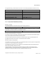
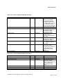
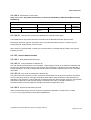
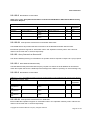
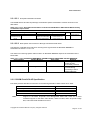
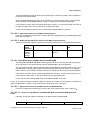
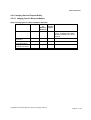
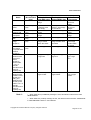
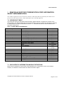
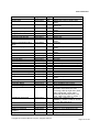
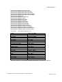
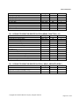
Table 0.1 provides an overview of the network services supported by the GEHC MR products.
Table 0.1 – NETWORK SERVICES
SOP Classes
User of Service
(SCU)
Provider of
Service (SCP)
Transfer
Verification (Echo)
CT Image Storage
MR Image Storage
Secondary Capture Image Storage
Grayscale Softcopy Presentation State Storage
GEMS PET Raw Information Storage
Enhanced SR
Positron Emission Tomography Image Storage
RT Structure Set Storage
Encapsulated Document SOP Class
Yes
Yes
Yes
Yes
Yes
Yes
Yes
Yes
Yes
Yes
Yes
Yes
Yes
Yes
No
Yes
Yes
Yes
Yes
No
Yes
Yes
Yes
Yes
Yes
No
Yes
Yes
Yes
No
No
No
Yes
Yes
Yes
No
No
No
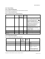
Query/Retrieve
Study Root Query/Retrieve Information Model –
FIND
Study Root Query/Retrieve Information Model –
MOVE
Print Management
Basic Grayscale Print Management Meta SOP
Class
Basic Color Print Management Meta SOP Class
Print Job SOP Class
Printer SOP Class
Workflow Management
Storage Commitment Push Model SOP Class
Modality Performed Procedure Step SOP Class
Modality Worklist Information Model – FIND SOP
Class
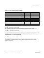
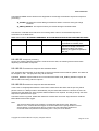
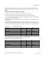
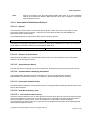
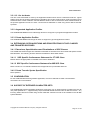
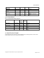
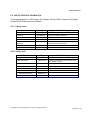
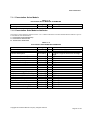
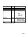
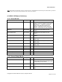
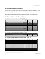
Table 0.2 provides an overview of the Media Storage Application Profiles supported by the GEHC MR
products specified in this document.
Table 0.2 - MEDIA SERVICES
Media Storage Application Profile
Write Files
(FSC or FSU)
Read Files
(FSR)
Compact Disk – Recordable
General Purpose CD-R
Yes (FSC)
Yes
Yes (FSC)
Yes
Yes (FSC)
Yes
DVD
General Purpose JPEG DVD
USB
General Purpose JPEG USB
Copyright 2013 General Electric Company. All rights reserved
Page 2 of 139
DOC1312097 Rev 1
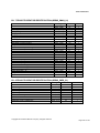
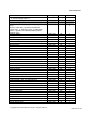
Table of Contents
GE HEALTHCARE
1
TECHNICAL PUBLICATIONS
1
DOC1312097
1
REVISION 1
1
1
2
INTRODUCTION
16
1.1
OVERVIEW
16
1.2
OVERALL DICOM CONFORMANCE STATEMENT DOCUMENT STRUCTURE
17
1.3
INTENDED AUDIENCE:
18
1.4
SCOPE AND FIELD OF APPLICATION
18
1.5
IMPORTANT REMARKS
19
1.6
REFERENCES
19
1.7
DEFINITIONS
20
1.8
Symbols and Abbreviations
21
NETWORK CONFORMANCE STATEMENT
2.1
INTRODUCTION
2.2
IMPLEMENTATION MODEL
2.2.1
DICOM Server AE
2.2.1.1 Application Data Flow Diagram
2.2.1.2 Functional Definition of AE’s
2.2.1.3 Sequencing of Real-World Activities
2.2.2
DICOM Print SCU
2.2.2.1 Application Data Flow Diagram
2.2.2.2 Functional Definition of AE’s
2.2.2.3 Sequencing of Real-World Activities
2.2.3
Modality Worklist Server
2.2.3.1 Application Data Flow Diagram
2.2.3.2 Functional Definition of AE's
2.2.3.3 Sequencing of Real-World Activities
2.2.4
PPS Dicom SCU AE
2.2.4.1 Application Data Flow Diagram
22
22
22
22
23
24
25
26
26
26
26
27
27
28
28
28
28
Copyright 2013 General Electric Company. All rights reserved
Page 3 of 139
DOC1312097 Rev 1
2.2.4.2
2.2.4.3
Functional Definition of AEs
Sequencing of Real-World Activities
29
29
2.3
AE SPECIFICATIONS
2.3.1
DICOM Server AE Specification
2.3.1.1 Association Establishment Policy
2.3.1.2 Association Initiation by Real-World Activity
2.3.1.3 Association Acceptance Policy
2.3.2
DICOM Print SCU AE Specification
2.3.2.1 Association Establishment Policies
2.3.2.2 Basic Film Session SOP Class
2.3.2.3 Basic Film Box SOP Class
2.3.2.4 Basic Grayscale Image Box SOP Class
2.3.2.5 Basic Color Image Box SOP Class
2.3.2.6 Printer SOP Class
2.3.2.7 Print Job SOP Class
2.3.2.8 Association Acceptance Policy
2.3.3
Worklist Server AE Specification
2.3.3.1 Association Establishment Policies
2.3.3.2 Association Initiation Policy
2.3.3.3 Association Acceptance Policy
2.3.4
PPS DICOM SCU Specification
2.3.4.1 Association Establishment Policies
2.3.4.2 Association Initiation Policy
2.3.4.3 Association Acceptance Policy
30
30
31
32
43
51
52
53
54
56
56
57
58
58
58
58
59
62
62
62
63
64
2.4
COMMUNICATION PROFILES
2.4.1
Supported Communication Stacks (part 8)
2.4.2
TCP/IP Stack
2.4.2.1 Physical Media Support
2.4.3
Additional Protocols
2.4.4
IPv4 and IPv6 Support
64
64
64
64
64
64
2.5
EXTENSIONS / SPECIALIZATIONS / PRIVATIZATIONS
2.5.1
Specialized Information Object Definition
2.5.2
Private Data Elements
64
64
64
2.6
CONFIGURATION
2.6.1
DICOM Server AE Configuration
2.6.1.1 AE Title/Presentation Address Mapping
2.6.1.2 Configurable Parameters
2.6.2
DICOM Print SCU Configuration
2.6.2.1 AE Title/Presentation Address Mapping
2.6.2.2 Configurable Parameters
2.6.3
PPS Dicom SCU
2.6.3.1 AE Title/Presentation address Mapping
2.6.4
Modality Workflist Server Configuration
2.6.4.1 AE Title/Presentation address Mapping
2.6.4.2 Configurable Parameters
65
65
65
65
65
65
65
66
66
66
66
67
2.7
SUPPORT OF EXTENDED CHARACTER SETS
67
2.8
CODES AND CONTROLLED TERMINOLOGY
67
2.9
SECURITY PROFILES
67
Copyright 2013 General Electric Company. All rights reserved
Page 4 of 139
DOC1312097 Rev 1
3
MEDIA STORAGE CONFORMANCE STATEMENT
3.0
68
Introduction
68
3.1
IMPLEMENTATION MODEL
3.1.1
Application Data Flow Diagram
3.1.2
Functional Definitions of AE's
3.1.2.1 Functional Definition of the CD/DVD/USB Storage DICOM Media Server AE
3.1.3
Sequencing Requirements
3.1.3.1 Sequencing of CD-R/DVD-R/USB Storage Real World Activities
68
68
69
69
69
69
3.2
AE SPECFICIATIONS
70
3.2.1
DICOM CD-R/CD-RW/DVD-R/DVD-RW/USB Media Interchange AE Specification
70
3.2.1.1 File Meta Information for the CD-R/CD-RW/DVD-R/DVD-RW/USB DICOM Media Interchange
Application Entity
70
3.2.1.2 Real-World Activities for the CD-R/CD-RW/DVD-R/DVD-RW/USB DICOM Media Interchange
Application Entity
70
3.2.2
File Meta Information for Implementation Class and Version
73
3.3
AUGMENTED AND PRIVATE APPLICATION PROFILES
3.3.1.1 Roles and Service Class Options
3.3.2
Augmented Application Profiles
3.3.3
Private Application Profiles
73
73
74
74
3.4
EXTENSIONS, SPECIALIZATIONS AND PRIVATIZATIONS OF SOP CLASSES AND TRANSFER
SYNTAXES
74
3.4.1
Extensions, Specializations and Privatizations of SOP Classes
74
3.4.1.1 SOP Specific Conformance Statement for CT SOP Class
74
3.4.1.2 SOP Specific Conformance Statement for MR SOP Class
74
3.4.2
Private Transfer Syntax Specification
74
4
3.5
CONFIGURATION
74
3.6
SUPPORT OF EXTENDED CHARACTER SETS
74
MODALITY WORKLIST INFORMATION MODEL DESCRIPTION
75
4.0
MODALITY WORKLIST INFORMATION MODEL ENTITY-RELATIONSHIP MODEL
4.0.1
Entity Descriptions
4.0.1.1 Scheduled Procedure Step
4.0.1.2 Requested Procedure Entity Description
4.0.1.3 Imaging Service Request Entity Description
4.0.1.4 Visit Entity Description
4.0.1.5 Patient Entity Description
4.0.2
MR Systems Mapping of DICOM Entities
75
76
76
76
76
76
76
76
4.1
76
INFORMATION MODEL MODULE
4.2
INFORMATION MODEL KEYS
4.2.1
Supported Matching
4.2.2
Scheduled Procedure Step Entity
4.2.2.1 SOP Common Module
4.2.2.2 Scheduled Procedure Step Module
4.2.3
Requested Procedure Entity
77
78
78
78
78
80
Copyright 2013 General Electric Company. All rights reserved
Page 5 of 139
DOC1312097 Rev 1
4.2.3.1 Requested Procedure Module
4.2.4
Imaging Service Request Entity
4.2.4.1 Imaging Service Request Module
4.2.5
Visit Entity
4.2.5.1 Visit Identification
4.2.5.2 Visit Status
4.2.5.3 Visit Relationship
4.2.5.4 Visit Admission
4.2.6
Patient Entity
4.2.6.1 Patient Relationship
4.2.6.2 Patient Identification
4.2.6.3 Patient Demographic
4.2.6.4 Patient Medical
4.3
5
6
PRIVATE DATA DICTIONARY
PERFORMED PROCEDURE STEP
80
81
81
82
82
82
82
82
83
83
83
83
84
84
85
5.0
N-CREATE & NSET REQUEST MESSAGE
85
5.1
USE OF SPECIFIC DICOM DATA
86
5.2
USE OF SPECIFIC DICOM DATA
5.2.1
Patient Level
5.2.2
Study Level
5.2.3
Series Level
90
90
90
91
STORAGE COMMITMENT CONFORMANCE
6.0
INTRODUCTION
6.1
Storage Commitment Push Model Information Object Definition
6.1.1
STORAGE COMMITMENT MODULE FOR N-ACTION
6.1.2
STORAGE COMMITMENT MODULE FOR N-EVENT-REPORT
92
92
92
92
93
7 GRAYSCALE SOFTCOPY PRESENTATION STATE INFORMATION OBJECT
IMPLEMENTATION
94
7.0
IOD MODULE TABLE
7.1
GSPS-SPECIFIC INFORMATION MODULE DEFINITIONS
7.1.1
Presentation Series Module
7.1.2
Presentation State Modules Attributes
7.1.3
Display Shutter Module
7.1.4
Bitmap Display Shutter Module
7.1.5
Overlay/Curve Activation Module
7.1.6
Displayed Area Module
7.1.7
Graphic Annotation Module
7.1.8
Spatial Transformation Module
7.1.9
Graphic Layer Module
7.1.10
Softcopy VOI LUT Acquisition Module
7.1.11
Softcopy Presentation LUT Module
94
94
95
95
96
96
96
97
98
98
99
99
99
Copyright 2013 General Electric Company. All rights reserved
Page 6 of 139
DOC1312097 Rev 1
8
ENHANCED STRUCTURED REPORT INFORMATION OBJECT IMPLEMENTATION
100
8.0
IOD MODULE TABLE
100
8.1
INFORMATION MODULE DEFINITIONS
8.1.1
SR Document Series Module
8.1.2
SR Document General Module
8.1.3
SR Document Content Module
8.1.3.1 SR Document Content Descriptions
8.1.4
SOP Common Module
100
100
101
101
102
103
8.2
STANDARD EXTENDED AND PRIVATE DATA ATTRIBUTES
8.2.1
Private Group GEMS_0039
103
103
8.3
STANDARD EXTENDED AND PRIVATE CONTEXT GROUPS
103
8.4
STANDARD EXTENDED AND PRIVATE TEMPLATES
103
9
SECURITY CONFORMANCE STATEMENT
104
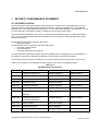
9.0
DE-IDENTIFICATION
104
9.1
ASSOCIATION LEVEL SECURITY
108
A.
APPENDIX STANDARD DATA ELEMENTS
108
A.1 MR Specific IOD Definition
A.1.1 MR IMAGE IOD MODULES
A.1.2 MR Image Module
A.1.3 Image Plane Module
A.1.4 Contrast Bolus Module
A.1.5 Frame of Reference Module
A.1.6 DICOM attributes used in GE MR images (Meta Header Module)
109
109
109
111
111
111
112
A.2 SC Specific IOD Definition
A.2.1 SC Image IOD Modules
A.2.2 SC Equipment Module
A.2.3 Encapsulated Document Series Module
A.2.4 Encapsulated Document Module
112
112
112
113
113
A.3 MR/SC IOD Module Definitions
A.3.1 Patient Module
A.3.2 General Study Module
A.3.3 Patient Study Module
A.3.4 General Series Module
A.3.5 General Equipment Module
A.3.6 General Image Module
A.3.7 Image Pixel Module
A.3.8 SOP Common Module
A.3.9 VOI LUT Module
A.3.10 Additional Attributes
A.3.11 Specialized Information Object Definition
114
114
114
115
116
117
117
118
118
119
119
120
Copyright 2013 General Electric Company. All rights reserved
Page 7 of 139
DOC1312097 Rev 1
B.
APPENDIX PRIVATE DATA ELEMENTS
B.1 MR Image IOD Private Data Elements Definition
B.1.1 Private Creator Identification (GEMS_IDEN_01)
B.1.2 Private Creator Identification (GEMS_PATI_01)
B.1.3 PRIVATE CREATOR IDENTIFICATION (GEMS_ACQU_01)
B.1.4 PRIVATE CREATOR IDENTIFICATION (GEMS_RELA_01)
B.1.5 PRIVATE CREATOR IDENTIFICATION (GEMS_STDY_01)
B.1.6 PRIVATE CREATOR IDENTIFICATION (GEMS_SERS_01)
B.1.7 PRIVATE CREATOR IDENTIFICATION (GEMS_IMAG_01)
B.1.8 PRIVATE CREATOR IDENTIFICATION (GEMS_IMPS_01)
B.1.9 PRIVATE CREATOR IDENTIFICATION (GEMS_PARM_01)
B.1.10 PRIVATE CREATOR IDENTIFICATION (BRAINWAVE: 1.2.840.113819.3)
B.1.11 PRIVATE CREATOR IDENTIFICATION (GEMS_MR_RAW_01)
B.1.12 PRIVATE CREATOR IDENTIFICATION (GEMS_FUNCTOOL_01)
B.1.13 PRIVATE CREATOR IDENTIFICATION (“GEHC_REPORTCARD0”)
C.
122
122
122
122
122
124
125
125
126
126
127
130
130
131
131
APPENDIX DICOMDIR DIRECTORY INFORMATION
132
C.1 DICOMDIR DIRECTORY INFORMATION
C.1.1 BASIC DIRECTORY IOD DEFINITION
C.1.2 DIRECTORY INFORMATION MODULE
C.1.2.1 CD-R/CD-RW/DVD-R/DVD-RW/USB Directory Information Module
132
132
132
132
C.1.3 CD-R/CD-RW/DVD-R/DVD-RW/USB DIRECTORY RECORD SELECTION KEYS
C.1.3.1 CD-R/CD-RW/DVD-R/DVD-RW/USB Patient Keys
C.1.3.2 CD-R/CD-RW/DVD-R/DVD-RW/USB Study Keys
C.1.3.2.1 Method to set Study Data and Time
C.1.3.2.2 Method to set Study ID
C.1.3.3 CD-R/CD-RW/DVD-R/DVD-RW/USB Series Keys
C.1.3.3.1 Method to set Series Number
C.1.3.4 CD-R/CD-RW/DVD-R/DVD-RW/USB Image Keys
C.1.3.4.1 Method to set Instance Number
133
133
133
134
135
135
136
136
138
Copyright 2013 General Electric Company. All rights reserved
Page 8 of 139
DOC1312097 Rev 1
ПРЕДУПРЕЖДЕНИЕ Това упътване за работа е налично само на английски език.
(BG)
警告
Ако доставчикът на услугата на клиента изиска друг език, задължение на клиента е
да осигури превод.
•
Не използвайте оборудването, преди да сте се консултирали и разбрали
упътването за работа.
•
Неспазването на това предупреждение може да доведе до нараняване на
доставчика на услугата, оператора или пациентa в резултат на токов удар,
механична или друга опасност.
本维修手册仅提供英文版本。
(ZH-CN)
警告
•
如果客户的维修服务人员需要非英文版本,则客户需自行提供翻译服务。
•
未详细阅读和完全理解本维修手册之前,不得进行维修。
•
忽略本警告可能对维修服务人员、操作人员或患者造成电击、机械伤害或其他形式的伤
害。
本服務手冊僅提供英文版本。
(ZH-HK)
警告
•
倘若客
•
除非已參
•
不遵從本警告或會令服務供應商、網絡供應商或病人受到觸電、機械性或其他的危險。
供
,客
,
供
。
。
本維修手冊僅有英文版。
(ZH-TW)
UPOZORENJE
(HR)
VÝSTRAHA
(CS)
•
•
若客
•
請勿試圖維修本設備,除非 您已查閱並瞭解本維修手冊。
•
若未留意本警告,可能導致維修廠商、操作員或病患因觸電、機械或其他危險而受傷。
,
客
供
。
Ovaj servisni priručnik dostupan je na engleskom jeziku.
•
Ako davatelj usluge klijenta treba neki drugi jezik, klijent je dužan osigurati prijevod.
•
Ne pokušavajte servisirati opremu ako niste u potpunosti pročitali i razumjeli ovaj servisni
priručnik.
•
Zanemarite li ovo upozorenje, može doći do ozljede davatelja usluge, operatera ili
pacijenta uslijed strujnog udara, mehaničkih ili drugih rizika.
Tento provozní návod existuje pouze v anglickém jazyce.
•
V případě, že externí služba zákazníkům potřebuje návod v jiném jazyce, je zajištění
překladu do odpovídajícího jazyka úkolem zákazníka.
•
Nesnažte se o údržbu tohoto zařízení, aniž byste si přečetli tento provozní návod a
Copyright 2013 General Electric Company. All rights reserved
Page 9 of 139
DOC1312097 Rev 1
pochopili jeho obsah.
•
ADVARSEL
(DA)
WAARSCHUWING
(NL)
WARNING
(EN)
HOIATUS
(ET)
VAROITUS
(FI)
V případě nedodržování této výstrahy může dojít k poranění pracovníka prodejního
servisu, obslužného personálu nebo pacientů vlivem elektrického proudu, respektive
vlivem mechanických či jiných rizik.
Denne servicemanual findes kun på engelsk.
•
Hvis en kundes tekniker har brug for et andet sprog end engelsk, er det kundens ansvar
at sørge for oversættelse.
•
Forsøg ikke at servicere udstyret uden at læse og forstå denne servicemanual.
•
Manglende overholdelse af denne advarsel kan medføre skade på grund af elektrisk stød,
mekanisk eller anden fare for teknikeren, operatøren eller patienten.
Deze onderhoudshandleiding is enkel in het Engels verkrijgbaar.
•
Als het onderhoudspersoneel een andere taal vereist, dan is de klant verantwoordelijk
voor de vertaling ervan.
•
Probeer de apparatuur niet te onderhouden alvorens deze onderhoudshandleiding werd
geraadpleegd en begrepen is.
•
Indien deze waarschuwing niet wordt opgevolgd, zou het onderhoudspersoneel, de
operator of een patiënt gewond kunnen raken als gevolg van een elektrische schok,
mechanische of andere gevaren.
This service manual is available in English only.
•
If a customer's service provider requires a language other than English, it is the
customer's responsibility to provide translation services.
•
Do not attempt to service the equipment unless this service manual has been consulted
and is understood.
•
Failure to heed this warning may result in injury to the service provider, operator or patient
from electric shock, mechanical or other hazards.
See teenindusjuhend on saadaval ainult inglise keeles.
•
Kui klienditeeninduse osutaja nõuab juhendit inglise keelest erinevas keeles, vastutab
klient tõlketeenuse osutamise eest.
•
Ärge üritage seadmeid teenindada enne eelnevalt käesoleva teenindusjuhendiga
tutvumist ja sellest aru saamist.
•
Käesoleva hoiatuse eiramine võib põhjustada teenuseosutaja, operaatori või patsiendi
vigastamist elektrilöögi, mehaanilise või muu ohu tagajärjel.
Tämä huolto-ohje on saatavilla vain englanniksi.
•
Jos asiakkaan huoltohenkilöstö vaatii muuta kuin englanninkielistä materiaalia, tarvittavan
käännöksen hankkiminen on asiakkaan vastuulla.
•
Älä yritä korjata laitteistoa ennen kuin olet varmasti lukenut ja ymmärtänyt tämän huolto-
Copyright 2013 General Electric Company. All rights reserved
Page 10 of 139
DOC1312097 Rev 1
ohjeen.
•
ATTENTION
(FR)
WARNUNG
(DE)
ΠΡΟΕΙ∆ΟΠΟΙΗΣΗ
(EL)
FIGYELMEZTETÉS
(HU)
AÐVÖRUN
(IS)
Mikäli tätä varoitusta ei noudateta, seurauksena voi olla huoltohenkilöstön, laitteiston
käyttäjän tai potilaan vahingoittuminen sähköiskun, mekaanisen vian tai muun
vaaratilanteen vuoksi.
Ce manuel d’installation et de maintenance est disponible uniquement en anglais.
•
Si le technicien d'un client a besoin de ce manuel dans une langue autre que l'anglais, il
incombe au client de le faire traduire.
•
Ne pas tenter d'intervenir sur les équipements tant que ce manuel d’installation et de
maintenance n'a pas été consulté et compris.
•
Le non-respect de cet avertissement peut entraîner chez le technicien, l'opérateur ou le
patient des blessures dues à des dangers électriques, mécaniques ou autres.
Diese Serviceanleitung existiert nur in englischer Sprache.
•
Falls ein fremder Kundendienst eine andere Sprache benötigt, ist es Aufgabe des Kunden
für eine entsprechende Übersetzung zu sorgen.
•
Versuchen Sie nicht diese Anlage zu warten, ohne diese Serviceanleitung gelesen und
verstanden zu haben.
•
Wird diese Warnung nicht beachtet, so kann es zu Verletzungen des
Kundendiensttechnikers, des Bedieners oder des Patienten durch Stromschläge,
mechanische oder sonstige Gefahren kommen.
Το παρόν εγχειρίδιο σέρβις διατίθεται µόνο στα αγγλικά.
•
Εάν ο τεχνικός σέρβις ενός πελάτη απαιτεί το παρόν εγχειρίδιο σε γλώσσα εκτός των
αγγλικών, αποτελεί ευθύνη του πελάτη να παρέχει τις υπηρεσίες µετάφρασης.
•
Μην επιχειρήσετε την εκτέλεση εργασιών σέρβις στον εξοπλισµό αν δεν έχετε
συµβουλευτεί και κατανοήσει το παρόν εγχειρίδιο σέρβις.
•
Αν δεν προσέξετε την προειδοποίηση αυτή, ενδέχεται να προκληθεί τραυµατισµός στον
τεχνικό σέρβις, στο χειριστή ή στον ασθενή από ηλεκτροπληξία, µηχανικούς ή άλλους
κινδύνους.
Ezen karbantartási kézikönyv kizárólag angol nyelven érhető el.
•
Ha a vevő szolgáltatója angoltól eltérő nyelvre tart igényt, akkor a vevő felelőssége a
fordítás elkészíttetése.
•
Ne próbálja elkezdeni használni a berendezést, amíg a karbantartási kézikönyvben
leírtakat nem értelmezték.
•
Ezen figyelmeztetés figyelmen kívül hagyása a szolgáltató, működtető vagy a beteg
áramütés, mechanikai vagy egyéb veszélyhelyzet miatti sérülését eredményezheti.
Þessi þjónustuhandbók er aðeins fáanleg á ensku.
•
Ef að þjónustuveitandi viðskiptamanns þarfnast annas tungumáls en ensku, er það skylda
viðskiptamanns að skaffa tungumálaþjónustu.
Copyright 2013 General Electric Company. All rights reserved
Page 11 of 139
DOC1312097 Rev 1
AVVERTENZA
Reynið ekki að afgreiða tækið nema að þessi þjónustuhandbók hefur verið skoðuð og
skilin.
•
Brot á sinna þessari aðvörun getur leitt til meiðsla á þjónustuveitanda, stjórnanda eða
sjúklings frá raflosti, vélrænu eða öðrum áhættum.
Il presente manuale di manutenzione è disponibile soltanto in lingua inglese.
(IT)
警告 (JA)
•
•
Se un addetto alla manutenzione richiede il manuale in una lingua diversa, il cliente è
tenuto a provvedere direttamente alla traduzione.
•
Procedere alla manutenzione dell'apparecchiatura solo dopo aver consultato il presente
manuale ed averne compreso il contenuto.
•
Il mancato rispetto della presente avvertenza potrebbe causare lesioni all'addetto alla
manutenzione, all'operatore o ai pazienti provocate da scosse elettriche, urti meccanici o
altri rischi.
このサービスマニュアルには英語版しかありません。
•
サービスを担当される業者が英語以外の言語を要求される場合、翻訳作業はその業
者の責任で行うものとさせていただきます。
•
このサービスマニュアルを熟読し理解せずに、装置のサービスを行わないでくださ
い。
•
この警告に従わない場合、サービスを担当される方、操作員あるいは患者
さんが、感電や機械的又はその他の危険により負傷する可能性があります。
경고
본 서비스 매뉴얼은 영어로만 이용하실 수 있습니다.
(KO)
•
고객의 서비스 제공자가 영어 이외의 언어를 요구할 경우, 번역 서비스를 제공하는 것은 고객의
책임입니다.
•
본 서비스 매뉴얼을 참조하여 숙지하지 않은 이상 해당 장비를 수리하려고 시도하지 마십시오.
•
본 경고 사항에 유의하지 않으면 전기 쇼크, 기계적 위험, 또는 기타 위험으로 인해 서비스
제공자, 사용자 또는 환자에게 부상을 입힐 수 있습니다.
BRĪDINĀJUMS Šī apkopes rokasgrāmata ir pieejama tikai angļu valodā.
(LV)
ĮSPĖJIMAS
•
Ja klienta apkopes sniedzējam nepieciešama informācija citā valodā, klienta
pienākums ir nodrošināt tulkojumu.
•
Neveiciet aprīkojuma apkopi bez apkopes rokasgrāmatas izlasīšanas un
saprašanas.
•
Šī brīdinājuma neievērošanas rezultātā var rasties elektriskās strāvas trieciena,
mehānisku vai citu faktoru izraisītu traumu risks apkopes sniedzējam, operatoram
vai pacientam.
Šis eksploatavimo vadovas yra tik anglų kalba.
Copyright 2013 General Electric Company. All rights reserved
Page 12 of 139
DOC1312097 Rev 1
(LT)
ADVARSEL
(NO)
•
Jei kliento paslaugų tiekėjas reikalauja vadovo kita kalba – ne anglų, suteikti
vertimo paslaugas privalo klientas.
•
Nemėginkite atlikti įrangos techninės priežiūros, jei neperskaitėte ar nesupratote
šio eksploatavimo vadovo.
•
Jei nepaisysite šio įspėjimo, galimi paslaugų tiekėjo, operatoriaus ar paciento
sužalojimai dėl elektros šoko, mechaninių ar kitų pavojų.
Denne servicehåndboken finnes bare på engelsk.
•
Hvis kundens serviceleverandør har bruk for et annet språk, er det kundens ansvar
å sørge for oversettelse.
•
Ikke forsøk å reparere utstyret uten at denne servicehåndboken er lest og forstått.
•
Manglende hensyn til denne advarselen kan føre til at serviceleverandøren,
operatøren eller pasienten skades på grunn av elektrisk støt, mekaniske eller andre
farer.
OSTRZEŻENIE Niniejszy podręcznik serwisowy dostępny jest jedynie w języku angielskim.
(PL)
ATENÇÃO
(PT-BR)
ATENÇÃO
(PT-PT)
ATENŢIE
•
Jeśli serwisant klienta wymaga języka innego niż angielski, zapewnienie usługi
tłumaczenia jest obowiązkiem klienta.
•
Nie próbować serwisować urządzenia bez zapoznania się z niniejszym
podręcznikiem serwisowym i zrozumienia go.
•
Niezastosowanie się do tego ostrzeżenia może doprowadzić do obrażeń
serwisanta, operatora lub pacjenta w wyniku porażenia prądem elektrycznym,
zagrożenia mechanicznego bądź innego.
Este manual de assistência técnica encontra-se disponível unicamente em inglês.
•
Se outro serviço de assistência técnica solicitar a tradução deste manual, caberá
ao cliente fornecer os serviços de tradução.
•
Não tente reparar o equipamento sem ter consultado e compreendido este manual
de assistência técnica.
•
A não observância deste aviso pode ocasionar ferimentos no técnico, operador ou
paciente decorrentes de choques elétricos, mecânicos ou outros.
Este manual de assistência técnica só se encontra disponível em inglês.
•
Se qualquer outro serviço de assistência técnica solicitar este manual noutro
idioma, é da responsabilidade do cliente fornecer os serviços de tradução.
•
Não tente reparar o equipamento sem ter consultado e compreendido este manual
de assistência técnica.
•
O não cumprimento deste aviso pode colocar em perigo a segurança do técnico,
do operador ou do paciente devido a choques eléctricos, mecânicos ou outros.
Acest manual de service este disponibil doar în limba engleză.
Copyright 2013 General Electric Company. All rights reserved
Page 13 of 139
DOC1312097 Rev 1
(RO)
•
Dacă un furnizor de servicii pentru clienţi necesită o altă limbă decât cea engleză,
este de datoria clientului să furnizeze o traducere.
•
Nu încercaţi să reparaţi echipamentul decât ulterior consultării şi înţelegerii acestui
manual de service.
•
Ignorarea acestui avertisment ar putea duce la rănirea depanatorului, operatorului
sau pacientului în urma pericolelor de electrocutare, mecanice sau de altă natură.
ОСТОРОЖНО! Данное руководство по техническому обслуживанию представлено только на
английском языке.
(RU)
• Если сервисному персоналу клиента необходимо руководство не на
английском, а на каком-то другом языке, клиенту следует самостоятельно
обеспечить перевод.
•
Перед техническим обслуживанием оборудования обязательно обратитесь к
данному руководству и поймите изложенные в нем сведения.
•
Несоблюдение требований данного предупреждения может привести к тому,
что специалист по техобслуживанию, оператор или пациент получит удар
электрическим током, механическую травму или другое повреждение.
UPOZORENJE Ovo servisno uputstvo je dostupno samo na engleskom jeziku.
(SR)
•
Ako klijentov serviser zahteva neki drugi jezik, klijent je dužan da obezbedi
prevodilačke usluge.
•
Ne pokušavajte da opravite uređaj ako niste pročitali i razumeli ovo servisno
uputstvo.
•
Zanemarivanje ovog upozorenja može dovesti do povređivanja servisera,
rukovaoca ili pacijenta usled strujnog udara ili mehaničkih i drugih opasnosti.
UPOZORNENIE Tento návod na obsluhu je k dispozícii len v angličtine.
(SK)
ATENCION
(ES)
•
Ak zákazníkov poskytovateľ služieb vyžaduje iný jazyk ako angličtinu, poskytnutie
prekladateľských služieb je zodpovednosťou zákazníka.
•
Nepokúšajte sa o obsluhu zariadenia, kým si neprečítate návod na obluhu a
neporozumiete mu.
•
Zanedbanie tohto upozornenia môže spôsobiť zranenie poskytovateľa služieb,
obsluhujúcej osoby alebo pacienta elektrickým prúdom, mechanické alebo iné
ohrozenie.
Este manual de servicio sólo existe en inglés.
•
Si el encargado de mantenimiento de un cliente necesita un idioma que no sea el
inglés, el cliente deberá encargarse de la traducción del manual.
•
No se deberá dar servicio técnico al equipo, sin haber consultado y comprendido
este manual de servicio.
•
La no observancia del presente aviso puede dar lugar a que el proveedor de
servicios, el operador o el paciente sufran lesiones provocadas por causas
Copyright 2013 General Electric Company. All rights reserved
Page 14 of 139
DOC1312097 Rev 1
eléctricas, mecánicas o de otra naturaleza.
VARNING
(SV)
OPOZORILO
(SL)
DİKKAT
(TR)
Den här servicehandboken finns bara tillgänglig på engelska.
•
Om en kunds servicetekniker har behov av ett annat språk än engelska, ansvarar
kunden för att tillhandahålla översättningstjänster.
•
Försök inte utföra service på utrustningen om du inte har läst och förstår den här
servicehandboken.
•
Om du inte tar hänsyn till den här varningen kan det resultera i skador på
serviceteknikern, operatören eller patienten till följd av elektriska stötar, mekaniska
faror eller andra faror.
Ta servisni priročnik je na voljo samo v angleškem jeziku.
•
Če ponudnik storitve stranke potrebuje priročnik v drugem jeziku, mora stranka
zagotoviti prevod.
•
Ne poskušajte servisirati opreme, če tega priročnika niste v celoti prebrali in
razumeli.
•
Če tega opozorila ne upoštevate, se lahko zaradi električnega udara, mehanskih ali
drugih nevarnosti poškoduje ponudnik storitev, operater ali bolnik.
Bu servis kılavuzunun sadece ingilizcesi mevcuttur.
•
Eğer müşteri teknisyeni bu kılavuzu ingilizce dışında bir başka lisandan talep
ederse, bunu tercüme ettirmek müşteriye düşer.
•
Servis kılavuzunu okuyup anlamadan ekipmanlara müdahale etmeyiniz.
•
Bu uyarıya uyulmaması, elektrik, mekanik veya diğer tehlikelerden dolayı
teknisyen, operatör veya hastanın yaralanmasına yol açabilir.
Copyright 2013 General Electric Company. All rights reserved
Page 15 of 139
DOC1312097 Rev 1
1
INTRODUCTION
1.1 OVERVIEW
Section 1 Introduction, provides general information about the content and scope of this document.
Section 2 Network Conformance Statement, is the DICOM Conformance Statement related to
network communications of images, including query and retrieve.
Section 3 Media Storage Conformance Statement, is the DICOM Conformance Statement related to
Media Storage Application Profile.
Section 4 Modality Worklist, is the DICOM Conformance Statement related to the DICOM Modality
Worklist implementation on the covered systems.
Section 5 Performed Procedure Step Conformance Statement is the DICOM Conformance
Statement related to the DICOM PPS implementation on the covered systems.
Section 6 Storage Commitment Conformance Statement is the DICOM Conformance Statement
related to the DICOM storage commitment implementation on the covered systems.
Section 7 Grayscale Softcopy Presentation State Information Object specifies the compliance to the
DICOM requirements of Grayscale Softcopy Presentation State features.
Section 8 Enhanced Structured Report Information Object specifies the compliance to the DICOM
requirements of Structured Report features.
Section 9 Security Conformance Statement specifies the compliance to the DICOM requirements of
Security features.
Copyright 2013 General Electric Company. All rights reserved
Page 16 of 139
DOC1312097 Rev 1
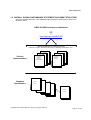
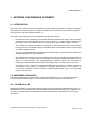
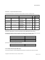
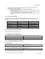
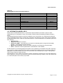
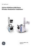
1.2 OVERALL DICOM CONFORMANCE STATEMENT DOCUMENT STRUCTURE
The Documentation Structure of the GEMS DICOM Conformance Statements is shown in the
Illustration below.
GEHC DICOM Conformance Statements
@
http://www.ge.com/DICOM
APPLICATION ENTITY SPECIFICATION
(SERVICE CLASSES, INFORMATION OBJECTS, MESSAGE EXCHANGES, ETC.)
Product
Implementation:
CT Advantage
Conformance
MR Advantage
Statement
Conformance
Direction:
GE MR Dicom
Statement
Conformance
Direction:
Statement
Direction:
DOC1312097
......
Conformance
Statement
Direction:
......
DICOM STANDARD
Standard
Specification:
DICOM
Part 1
DICOM
Part 2
DICOM
Part 3
DICOM
Part 4
DICOM
Part 16
Copyright 2013 General Electric Company. All rights reserved
Page 17 of 139
DOC1312097 Rev 1
This document specifies the DICOM implementation. It is entitled:
GE MR Dicom Conformance Statement
Direction DOC1312097
This DICOM Conformance Statement documents the DICOM Conformance Statement and Technical
Specification required to interoperate with the GEMS network interface.
The GEMS Conformance Statement, contained in this document, also specifies the Lower Layer
communications which it supports (e.g., TCP/IP). However, the Technical Specifications are defined in the
DICOM Part 8 standard.
For more information regarding DICOM, copies of the Standard may be obtained on the Internet at
http://medical.nema.org. Comments on the Standard may be addressed to:
DICOM Secretariat
NEMA
1300 N. 17th Street, Suite 1752
Rosslyn, VA 22209
USA
Phone: +1.703.841.3200
1.3 INTENDED AUDIENCE:
The reader of this document is concerned with software design and/or system integration issues. It is
assumed that the reader of this document is familiar with the DICOM Standard and with the terminology and
concepts which are used in that Standard.
1.4 SCOPE AND FIELD OF APPLICATION
This document is the DICOM Conformance Statement for GE MR systems and is necessary to insure proper
processing and interpretation of GE medical image data exchanged using DICOM. The GE Healthcare
Conformance Statements are available to the public.
The reader of this conformance statement should be aware that different GE devices are capable of using
different Information Object Definitions. For example, a GE CT scanner may send images using the CT
Information Object, MR Information Object, Secondary Capture Object, etc.
Included in this Conformance Statement are Module Definitions which define all data elements used by this
GE Healthcare implementation. If the user encounters unspecified private data elements while parsing a GE
Data Set, the user is well advised to ignore those data elements (per the DICOM standard). Unspecified
private data element information is subject to change without notice. If, however, the device is acting as a
“full fidelity storage device”, it should retain and retransmit all of the private data elements which are sent by
GE devices.
Private data elements may be updated from one release to the next release. This is done in order to add
additional information or remove information that does not apply to the image object. Please refer to the
appropriate product release DICOM Conformance Statement for the list of private elements supported.
Copyright 2013 General Electric Company. All rights reserved
Page 18 of 139
DOC1312097 Rev 1
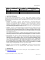
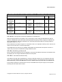
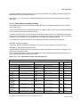
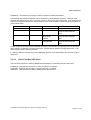
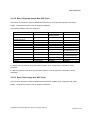
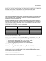
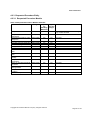
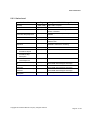
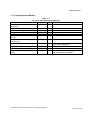
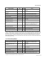
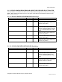
The following table provides the GE MR product(s) covered in this document and their specific details.
Software
Product name
Product
CD/DVD DICOM Implementation
version
Implementation UID
version name
TM
DV24
Discovery MR750w
1.2.840.113619.6.353
MergeCOM3_300
MergeCOM3_300
DV24
DiscoveryTM MR450
1.2.840.113619.6.353
TM
MergeCOM3_300
DV24
Discovery MR750
1.2.840.113619.6.353
MergeCOM3_300
DV24
Optima MR450w
1.2.840.113619.6.353
1.5 IMPORTANT REMARKS
The use of these Conformance Statements, in conjunction with the DICOM Standards, is intended to
facilitate communication with GE imaging equipment. However, by itself, it is not sufficient to insure that
inter-operation will be successful. The user (or user’s agent) needs to proceed with caution and address
at least four issues:
•
Integration - The integration of any device into an overall system of interconnected devices goes
beyond the scope of standards (DICOM), and of this introduction and associated Conformance
Statements when interoperability with non-GE equipment is desired. The responsibility to analyze the
applications requirements and to design a solution that integrates GE imaging equipment with non-GE
systems is the user’s responsibility and should not be underestimated. The user is strongly advised to
ensure that such integration analysis is correctly performed.
•
Validation - Testing the complete range of possible interactions between any GE device and non-GE
devices, before the connection is declared operational, should not be overlooked. Therefore, the user
should ensure that any non-GE provider accepts full responsibility for all validation required for their
connection with GE devices. This includes the accuracy of the image data once it has crossed the
interface between the GE imaging equipment and the non-GE device and the stability of the image data
for the intended applications.
Such a validation is required before any clinical use (diagnosis and/or treatment) is performed. It applies
when images acquired on GE imaging equipment are processed/displayed on a non-GE device, as well
as when images acquired on non-GE equipment is processed/displayed on a GE console or workstation.
•
Future Evolution - GE understands that the DICOM Standard will evolve to meet the user’s growing
requirements. GE is actively involved in the development of the DICOM Standard. DICOM will
incorporate new features and technologies and GE may follow the evolution of the Standard. The GE
Healthcare protocol is based on DICOM as specified in each DICOM Conformance Statement. Evolution
of the Standard may require changes to devices which have implemented DICOM. In addition, GE
reserves the right to discontinue or make changes to the support of communications features
(on its products) reflected by these DICOM Conformance Statements. The user should ensure that
any non-GE provider, which connects with GE devices, also plans future evolution of the DICOM
standard. Failure to do so will likely result in the loss of function and/or connectivity as the DICOM
Standard changes and GE products are enhanced to support these changes.
•
Interaction - It is the sole responsibility of the non-GE provider to ensure that communications with the
interfaced equipment does not cause degradation of GE imaging equipment performance and/or
function.
1.6 REFERENCES
See Digital Imaging and Communications in Medicine (DICOM) parts 1 through 18 (NEMA PS 3) available
free at http://medical.nema.org
Copyright 2013 General Electric Company. All rights reserved
Page 19 of 139
DOC1312097 Rev 1
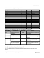
1.7 DEFINITIONS
Informal definitions are provided for the following terms used in this Conformance Statement. The DICOM
Standard is the authoritative source for formal definitions of these terms.
Abstract Syntax – the information agreed to be exchanged between applications, generally equivalent to a
Service/Object Pair (SOP) Class. Examples: Verification SOP Class, Modality Worklist Information Model
Find SOP Class, Computed Radiography Image Storage SOP Class.
Application Entity (AE) – an end point of a DICOM information exchange, including the DICOM network or
media interface software; i.e., the software that sends or receives DICOM information objects or messages.
A single device may have multiple Application Entities.
Application Entity Title – the externally known name of an Application Entity, used to identify a DICOM
application to other DICOM applications on the network.
Application Context – the specification of the type of communication used between Application Entities.
Example: DICOM network protocol.
Association – a network communication channel set up between Application Entities.
Attribute – – a unit of information in an object definition; a data element identified by a tag. The information
may be a complex data structure (Sequence), itself composed of lower level data elements. Examples:
Patient ID (0010,0020), Accession Number (0008,0050), Photometric Interpretation (0028,0004), Procedure
Code Sequence (0008,1032).
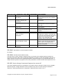
Information Object Definition (IOD) – the specified set of Attributes that comprise a type of data object;
does not represent a specific instance of the data object, but rather a class of similar data objects that have
the same properties. The Attributes may be specified as Mandatory (Type 1), Required but possibly
unknown (Type 2), or Optional (Type 3), and there may be conditions associated with the use of an Attribute
(Types 1C and 2C). Examples: MR Image IOD, CT Image IOD, Print Job IOD.
Joint Photographic Experts Group (JPEG) – a set of standardized image compression techniques,
available for use by DICOM applications.
Media Application Profile – the specification of DICOM information objects and encoding exchanged on
removable media (e.g., CDs)
Module – a set of Attributes within an Information Object Definition that are logically related to each other.
Example: Patient Module includes Patient Name, Patient ID, Patient Birth Date, and Patient Sex.
Negotiation – first phase of Association establishment that allows Application Entities to agree on the types
of data to be exchanged and how that data will be encoded.
Presentation Context – the set of DICOM network services used over an Association, as negotiated
between Application Entities; includes Abstract Syntaxes and Transfer Syntaxes.
Protocol Data Unit (PDU) – a packet (piece) of a DICOM message sent across the network. Devices must
specify the maximum size packet they can receive for DICOM messages.
Security Profile – a set of mechanisms, such as encryption, user authentication, or digital signatures, used
by an Application Entity to ensure confidentiality, integrity, and/or availability of exchanged DICOM data
Service Class Provider (SCP) – role of an Application Entity that provides a DICOM network service;
typically, a server that performs operations requested by another Application Entity (Service Class User).
Copyright 2013 General Electric Company. All rights reserved
Page 20 of 139
DOC1312097 Rev 1
Examples: Picture Archiving and Communication System (image storage SCP, and image query/retrieve
SCP), Radiology Information System (modality worklist SCP).
Service Class User (SCU) – role of an Application Entity that uses a DICOM network service; typically, a
client. Examples: imaging modality (image storage SCU, and modality worklist SCU), imaging workstation
(image query/retrieve SCU)
Service/Object Pair (SOP) Class – the specification of the network or media transfer (service) of a
particular type of data (object); the fundamental unit of DICOM interoperability specification. Examples:
Ultrasound Image Storage Service, Basic Grayscale Print Management.
Service/Object Pair (SOP) Instance – an information object; a specific occurrence of information
exchanged in a SOP Class. Examples: a specific x-ray image.
Tag – a 32-bit identifier for a data element, represented as a pair of four digit hexadecimal numbers, the
“group” and the “element”. If the “group” number is odd, the tag is for a private (manufacturer-specific) data
element. Examples: (0010,0020) [Patient ID], (07FE,0010) [Pixel Data], (0019,0210) [private data element]
Transfer Syntax – the encoding used for exchange of DICOM information objects and messages.
Examples: JPEG compressed (images), little endian explicit value representation.
Unique Identifier (UID) – a globally unique “dotted decimal” string that identifies a specific object or a class
of objects; an ISO-8824 Object Identifier. Examples: Study Instance UID, SOP Class UID, SOP Instance
UID.
Value Representation (VR) – the format type of an individual DICOM data element, such as text, an integer,
a person’s name, or a code. DICOM information objects can be transmitted with either explicit identification
of the type of each data element (Explicit VR), or without explicit identification (Implicit VR); with Implicit VR,
the receiving application must use a DICOM data dictionary to look up the format of each data element.
1.8 Symbols and Abbreviations
AE
Application Entity
DHCP Dynamic Host Configuration Protocol
DICOM Digital Imaging and Communications in Medicine
DNS Domain Name System
FSC
File-Set Creator
FSU
File-Set Updater
FSR
File-Set Reader
GSPS Grayscale Softcopy Presentation State
IHE
Integrating the Healthcare Enterprise
IOD
Information Object Definition
MPPS Modality Performed Procedure Step
MR
Magnetic Resonance Imaging
MWL Modality Worklist
SC
Secondary Capture
SPS
Scheduled Procedure Step
Copyright 2013 General Electric Company. All rights reserved
Page 21 of 139
DOC1312097 Rev 1
2
NETWORK CONFORMANCE STATEMENT
2.1 INTRODUCTION
This section of the DICOM Conformance Statement specifies the DV24 workstation’s compliance to DICOM
requirements for networking features. It details the DICOM Service Classes and roles which are supported
by this product in the versions listed in Section 1.4.
This section of the DICOM Conformance Statement describes the following:
•
DICOM Server AE’s compliance to the DICOM standards assembled with image object networking.
DICOM Server AE uses DICOM services to import images for possible further analysis and/or
processing. It also uses DICOM services to export images to other DICOM-compliant machines.
•
The compliance to DICOM conformance requirements for the relevant Grayscale and Color Network
Printing features on the GE MR system. The GE MR system uses DICOM Print SCU to print images
on DICOM Compliant Printers.
•
The use of the DICOM Modality Worklist Information Model used to organize data and against which
a Modality Worklist Query will be performed
•
The compliance to DICOM conformance requirements for the Performed Procedure Step feature on
this GEHC product. The PPS option for the GE MR system allows a Modality Performed Procedure
Step to be communicated to the Hospital/Radiology information system. The PPS feature is
providing the DICOM Modality Performed Procedure Step service as a service class user (SCU).
This feature works in conjunction with DICOM Modality Work-list feature, if installed. However the
conformance of this feature is independent of Modality work-list feature. For information on
conformance of Modality Work-List feature to DICOM standard please refer to the appropriate
section of the document.
2.2 IMPLEMENTATION MODEL
This section will describe the implementation model for DICOM Server AE in 2.2.1, DICOM Print SCU in
2.2.2, Modality Worklist Server AE in 2.2.3 and Performed Procedure Step Dicom SCU AE in 2.2.4.
2.2.1 DICOM Server AE
All DICOM functionality on the GE MR system is handled by the DICOM Server Application Entity (AE). The
DICOM Server AE is commanded to perform DICOM services through the buttons and menu selections on
the main user interface panel. The DICOM Server AE is also listening to a pre-defined port for incoming
connections.
Copyright 2013 General Electric Company. All rights reserved
Page 22 of 139
DOC1312097 Rev 1
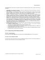
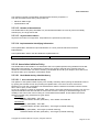
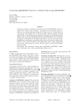
2.2.1.1 Application Data Flow Diagram
ILLUSTRATION 2.0
IMPLEMENTATION MODEL DATA FLOW DIAGRAM
DICOM Standard
Interface
Image
Remotely
Sent
1
Choose
Push
1
Choose
Query
Remote
2
Remote
Query
Retrieve
2
DICOM SERVER
AE
Choose
Pull
2
Choose
Remote
Archive
3
Remote
Pull
Request
2
Image
Remotely
Archived
3
Choose
DICOM
Ping
4
Verify
Request
4
Image
Installation
6
Query
Retrieve
SCP
7
Remote
system
requests
image storage
6
Remote
Query
Request
7
There are several Real-World Activities that will cause the DICOM Server Application Entity (DICOM Server
AE) to initiate a DICOM association to a remote DICOM Application Entity. Illustration 2.0 above shows
basic Real-World Activities.
The following paragraphs describe the Real-World Activities of Illustration 2.0:
1. The Choose Push Real-World Activity consists of an operator selecting one or more studies, series,
or images in the local database browser. The operator then clicks on the destination button in the
network panel at the bottom of the local database browser. Real-World Activity, Query Remote,
causes the DICOM Server AE to initiate an association to the Remote DICOM AE and request the
list of all studies. Once the DICOM Server AE receives the list of studies, the operator will have to
choose the study and the local database browser will list the series of the study chosen. After
Copyright 2013 General Electric Company. All rights reserved
Page 23 of 139
DOC1312097 Rev 1
receiving the list of series the DICOM Server AE will ask for the list of images for the series chosen
by the operator
2. Real-World Activity, Choose Pull, will be available once the Choose Query Remote activity is
performed. The operator can now select one or more studies (series or images) and ask the DICOM
Server AE to retrieve the selected image(s) from the Remote DICOM AE by clicking on the “Local
DB” button at the bottom of the local database browser.
3. The Choose Remote Archive Real-World activity consists of an operator choosing a remote
DICOM AE that supports Storage Commitment as provider from the archive panel at the bottom of
the local database browser. The operator chooses the exam or series in the local database browser
and clicks on the archival destination from the archive list at the bottom of the local database
browser. The Commitment request for the transferred image instances is sent after the complete
image transfer. The Commitment response can come on same association or on a different
association.
4. Real-World Activity, Click Choose DICOM Ping, consists of an operator selecting a Remote DICOM
AE from the “Network Configuration” window and clicking on “Ping” on the right side-bar. This is to
check to check the status of the selected remote DICOM AE.
6. The DICOM Server AE will perform the Real-World activity is Image Installation after the remote AE
sends an image to the GE MR system.
7. Once a Query Retrieve SCP request is received, the DICOM Server AE will search the local
database for all entries that match the keys requested by the Remote DICOM AE and send back the
list of matches. The DICOM Server AE will also respond to an incoming retrieval request from a
Remote AE by sending the image(s) to the Destination AE.
2.2.1.2 Functional Definition of AE’s
DICOM Server Application Entity initiates the following operations:
•
•
•
•
•
Initiate an association to a Remote AE for the purpose of sending images to the Remote AE. If the
Remote AE accepts the presentation context applicable to the image(s) being sent, the DICOM Server
AE will send the image(s) to the receiving Remote AE by invoking the C-STORE-RQ operation for each
image on the same association.
Initiate an association to a Remote AE for the purpose of committing images previously sent successfully
to the Remote AE for the purpose of the remote AE to commit to the storage of those images. If the
Remote AE accepts the presentation context, a storage commitment will be established with the Remote
AE with the DICOM Server AE sending the N-Action Request. The Remote AE completes the
commitment by sending the N-EVENT REPORT. The DICOM Server AE updates the archive flag in the
image browser for successful instances.
Initiate an association with a Remote AE to query for images on the remote host. A Study-Root StudyLevel C-FIND-RQ request will be sent to the Remote AE once an association has been established.
Once all the responses have been received the operator needs to select an exam in the local database
browser on selection of the exam the DICOM Server AE will issue a Series-Level C-FIND-RQ request to
get the series for a study in the list. Similarly the Image-Level C-FIND-RQ will be issued for the series
selected from the series list.
Send a C-MOVE-RQ request to a Remote AE for retrieve of images after successful association
establishment. The DICOM Server AE’s Storage SCP will receive the images over a separate
association.
Initiate an association with a Remote AE to verify its status with a C-ECHO-RQ. The Remote AE will
report its status in a C-ECHO-RSP.
Copyright 2013 General Electric Company. All rights reserved
Page 24 of 139
DOC1312097 Rev 1
The DICOM Server AE waits for association requests from Remote AEs that wish to perform the following
operations:
•
•
•
•
•
Verification: If a C-ECHO-RQ message is received, the DICOM Server AE will send back a C-ECHORSP message with a status of “success”.
Image Storage: If a C-STORE-RQ message is received, the DICOM Server AE will receive the image
and try to update the local database. If the image is stored successfully on storage media and the
database updated a status of “success” will be returned in a C-STORE-RSP message.
Query: If a C-FIND-RQ message is received the DICOM Server AE will search the database for the
requested attributes and send back a C-FIND-RSP message containing a match and a status of
“pending”. After all matching records have been sent, a status of “success’ will be returned in a C-FINDRSP message. The Remote AE can terminate the query by sending a C-CANCEL-FIND-RQ message.
Retrieve: If a C-MOVE-RQ message is received the DICOM Server AE will lookup its list of configured
Remote AEs for the Destination AE. If the Destination AE is configured, the DICOM Server AE will open
a new association to the Destination AE and use C-STORE-RQ to send the image(s). The DICOM
Server AE will send a C-MOVE-RSP message with a status of “pending” after every five images are
sent. When all images are sent or if DICOM Server AE receives a C-CANCEL-MOVE-RQ a final CSTORE-RSP will be sent back with an appropriate status.
Storage Commitment status: If a N-EVENT-REPORT request message is received, the DICOM Server
AE will perform the below activities:
• If Storage Commitment was successful, the “Archived” flag status of all the SOP instances
referenced in the N-EVENT-REPORT request will be changed to “Yes”.
• If the Storage Commitment failed, the “Archived” flag status of all the SOP instances is unaltered. All
the failed SOP instances are logged for reference.
• N-EVENT-REPORT response will be sent on the same association as N-EVENT-REPORT request.
No dataset will be sent along with the response.
2.2.1.3 Sequencing of Real-World Activities
2.2.1.3.1 Query Remote
Real-World Activity Query Remote must be performed before Choose Pull Option can be performed.
2.2.1.3.2 Chose Remote Archive
The user has to select exam\series from the local database browser and click on the archive destination in
the archive panel at the bottom of the local database browser.
Copyright 2013 General Electric Company. All rights reserved
Page 25 of 139
DOC1312097 Rev 1
2.2.2 DICOM Print SCU
The DICOM Print SCU is a DICOM print filter, which provides the capability to print images to DICOM
printers. The DICOM Print filter acts as an SCU of the DICOM print management SOP class.
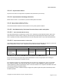
2.2.2.1 Application Data Flow Diagram
DICOM print SCU Implementation model
DICOM INTERFACE
Film
Composer
Print SCU
DICOM
Printer
Film Composer is the User Interface and is used to initiate the local real world activity. The user issues the
print request using Film Composer. Film Composer allows printer selection and composes the preformatted
film file. The film file is interpreted by the SCU, which sends the appropriate messages to DICOM print SCP
running on the DICOM printer.
2.2.2.2 Functional Definition of AE’s
DICOM Print SCU Establishes the Association with requested printer to print the composed film. If the
Remote AE accepts the presentation context applicable to the print job, the DICOM Print AE SCU will send
the print job to the receiving Remote AE by using the N-CREATE and N-SET services.
2.2.2.3 Sequencing of Real-World Activities
•
•
•
•
User has to select the DICOM printer from the Film Composer Interface.
The images to be printed shall be dragged and dropped into Film Composer slots from Viewing
Applications either manually or automatically.
In case of manual drag and drop, the user has to press the Print Button to print the images.
The Print SCU will start the Print Session. The Print Session involves establishing association with
the printer followed by the next sequence of activities:
o The Print SCU gets the Printer status using N-GET service. If the Printer returns FAILURE
status the print session will be terminated and the requester will be notified of the printer
status.
o The film session is created using N-CREATE service. In case of error, the print session will
be terminated. The attribute values for the Film session will be specified with the film session
request.
Copyright 2013 General Electric Company. All rights reserved
Page 26 of 139
DOC1312097 Rev 1
o
o
o
o
o
o
The film box is created using N-CREATE service. The print session will be terminated if the
printer fails to create the film box. The film box attribute values will be sent in the film box
create request.
The image attributes for the images to be printed in this session will be set using the N-SET
service. If the printer fails to accommodate the images in the image set, the print session
will be terminated.
The film will be printed using the N-ACTION service. Only film box printing is supported. In
case of error, the print session will be terminated.
The Film Box instance will be deleted using the N-DELETE service.
The SCU does not wait for N-EVENT-REPORT from the Printer after deleting the film box
instance. The N-EVENT-REPORT received when the association was still active is handled,
but the data received will be ignored.
Finally the association will be terminated and if all the above operations are successful the
requester will be notified of the successful print session. This status just indicates that the
images to be printed have been successfully sent to the printer.
2.2.3 Modality Worklist Server
All Modality Worklist DICOM functionality provided by the GE MR system is logically provided by the Worklist
Server DICOM AE. The Worklist Server DICOM AE is commanded to perform DICOM modality worklist
query services through the use of the Scanner’s user interface.
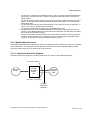
2.2.3.1 Application Data Flow Diagram
The Basic and Specific Application models for this device are shown in the following illustration:
Association Initiation
Worklist
Query
CT/MR
Worklist
Server
AE
Remote
Worklist
SCP
Association Acceptance
DICOM
Standard
Interface
Copyright 2013 General Electric Company. All rights reserved
Page 27 of 139
DOC1312097 Rev 1
2.2.3.2 Functional Definition of AE's
The Worklist Server AE is implemented as an application process on the scanner host computer. It operates
as a daemon serving requests from the user interface to obtain modality worklist, query remote AE’s and
return the results to the user interface.
The Worklist Server AE initiates the following functions:
Query: Initiates a DICOM association in order to query a remote AE. If the remote AE accepts a
presentation context applicable to modality worklist, the Worklist Server AE will issue a modality worklist
query request via the C-FIND service.
2.2.3.3 Sequencing of Real-World Activities
1. The user or the system initiates a modality worklist query (as a modality worklist SCU) to the modality
worklist SCP with a given set of query parameters.
2. The modality worklist SCP returns responses, which match the query parameters.
3. Items from the returned worklist responses are presented to the user.
4. A subset of attributes corresponding to operator selected returned worklist responses will be included in
acquired DICOM images related to the responses.
2.2.4 PPS Dicom SCU AE
The DICOM ‘Performed Procedure Step’ service is provided by the MPPS DICOM SCU. The MPPS DICOM
SCU is commanded to perform Modality Performed Procedure Step services automatically at the beginning
and end of acquisition.
2.2.4.1 Application Data Flow Diagram
The basic Application models for the feature are shown in the following illustration:
Patient Scan with
MWL data (automatic)
PPS Server
MPPS SCU
Remote
MPPS SCP
Patient Scan
without MWL data
(automatic)
DICOM
Standard
Interface
Copyright 2013 General Electric Company. All rights reserved
Page 28 of 139
DOC1312097 Rev 1
2.2.4.2 Functional Definition of AEs
The PPS DICOM SCU is implemented as an application process on the scanner host computer. It runs as a
daemon serving requests from other applications to send the PPS information to the remote AE and return
the results to the requesting application.
The PPS DICOM SCU initiates the following functions.
• Start PPS: Initiates a DICOM association in order to create a DICOM Modality Performed Procedure
Step SOP instance in the remote AE. If the remote AE accepts a presentation context applicable to Modality
performed Procedure Step, the PPS DICOM SCU will issue a request to create the SOP instance in the
remote AE via the N-CREATE service.
• Complete PPS: Initiates a DICOM association in order to update a DICOM Modality Performed Step
instance that is already created with the remote AE. If the remote AE accepts a presentation context
applicable to Modality performed Procedure Step, the PPS DICOM SCU will issue a request to update the
SOP instance in the remote AE via the N-SET service. The PPS Status is set to ‘COMPLETED’.
• Discontinue PPS: Initiates a DICOM association in order to update a DICOM Modality Performed Step
instance that is already created with the remote AE. If the remote AE accepts a presentation context
applicable to Modality performed Procedure Step, the PPS DICOM SCU will issue a request to update the
SOP instance in the remote AE via the N-SET service. The PPS Status is set to ‘DISCONTINUED’.
2.2.4.3 Sequencing of Real-World Activities
2.2.4.3.1 PPS from Acquisition System with MWL data
The system has a Modality Work-list Server AE installed. Work-List information is obtained from HIS/RIS
system through the use of Basic Work-list Management Service. Use of the information retrieved in the
creation of Image SOP instance is described in the Modality Work-list Conformance statement. Use of the
information retrieved in MPPS SOP instances is described later in this document.
• The system initiates a ‘Start PPS’ after the first image is acquired into the database. The system
retrieves necessary information related to the Scheduled Procedure Step from Modality Work-list Server.
PPS DICOM SCU initiates a MPPS (Modality Performed Procedure Step) N-CREATE request to the remote
AE (MPPS SCP), in-order to create a MPPS SOP instance at the remote AE.
• The MPPS SCP returns response indicating the success/failure of the request execution. The PPS state
information is updated in the system based on the response data. The DICOM association is closed.
• Please refer to Section 5.25.2 and 5.1 for specific Scheduled Procedure Step and Performed Procedure
Step information included by the system.
• At the end of image acquisition, system initiates a ‘Complete PPS’ or ‘Discontinue PPS’ based on the
choice selected by the user using the user interface provided.
• The remote AE returns response indicating the success/failure of the request execution. The PPS state
information is updated in the system based on the response data.
2.2.4.3.2 PPS from acquisition system without MWL data
The system either does not have a Modality Work-list Server AE installed or a Modality Work-list Server AE
installed but no Work-List information is obtained from HIS/RIS system for the current procedure that is being
performed. The information required for performing the procedure is supplied through the user interface of
the system. The use of this information in MPPS SOP instances is described later in this document.
Copyright 2013 General Electric Company. All rights reserved
Page 29 of 139
DOC1312097 Rev 1
• The system initiates a ‘Start PPS’ after the first image is acquired into the database. PPS DICOM SCU
initiates a MPPS (Modality Performed Procedure Step) N-CREATE request to the remote AE (MPPS SCP),
in-order to create a MPPS SOP instance at the remote AE.
• The MPPS SCP returns response indicating the success/failure of the request execution. The PPS state
information is updated in the system based on the response data. The DICOM association is closed.
• At the end of image acquisition, system initiates a ‘Complete PPS’ or ‘Discontinue PPS’ based on the
choice selected by the user using the user interface provided.
• The remote AE returns response indicating the success/failure of the request execution. The PPS state
information is updated in the system based on response data.
2.3 AE SPECIFICATIONS
2.3.1 DICOM Server AE Specification
The following tables detail the DICOM Classes supported as an SCP and an SCU. Although, the GE MR
systems accept other modality image types (CT, PET, RT, etc.), this conformance statement does not cover
other modality image and derived image types. Please refer to each modality DICOM Conformance
Statement for specific details.
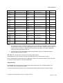
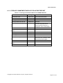
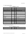
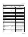
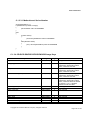
This Application Entity provides Standard Conformance to the following DICOM SOP Classes as an SCU:
SOP Class Name (SCU)
SOP Class UID
Verification (Echo)
1.2.840.10008.1.1
CT Image Information Storage
1.2.840.10008.5.1.4.1.1.2
MR Image Information Storage
1.2.840.10008.5.1.4.1.1.4
PET Image Information Storage
1.2.840.10008.5.1.4.1.1.128
RT Structure Set Storage
1.2.840.10008.5.1.4.1.1.481.3
GEMS PET Raw Information Storage
1.2.840.113619.4.30
Secondary Capture image storage
1.2.840.10008.5.1.4.1.1.7
Grayscale Softcopy Presentation State Storage*
1.2.840.10008.5.1.4.1.1.11.1
Enhanced Structured Report
1.2.840.10008.5.1.4.1.1.88.22
Study Root Query/Retrieve – FIND
1.2.840.10008.5.1.4.1.2.2.1
Study Root Query/Retrieve – MOVE
1.2.840.10008.5.1.4.1.2.2.2
Storage Commitment Push model SOP class
1.2.840.10008.1.20.1
Encapsulated Document SOP Class
1.2.840.10008.5.1.4.1.1.104.1
* This implementation does not support the following features of Grayscale Softcopy Presentation State:
Mask, Bitmap Display Shutter, Overlay Plane, Overlay/Curve Activation, and Modality LUT. All other
modules are supported. The GE MR systems can receive this object from other systems, but does not
support Mask, Bitmap Display Shutter, Overlay Plane, Overlay/Curve Activation, and Modality LUT.
Copyright 2013 General Electric Company. All rights reserved
Page 30 of 139
DOC1312097 Rev 1
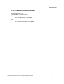
This Application Entity provides Standard Conformance to the following DICOM SOP classes as an SCP:
SOP Class Name (SCP)
Verification (Echo)
CT Information Storage
MR Information Storage
PET Image Information Storage
RT Structure Set Storage
GEMS PET Raw Information Storage
Secondary Capture Image storage
Enhanced Structured Report
Study Root Query/Retrieve – FIND
Study Root Query/Retrieve – MOVE
SOP Class UID
1.2.840.10008.1.1
1.2.840.10008.5.1.4.1.1.2
1.2.840.10008.5.1.4.1.1.4
1.2.840.10008.5.1.4.1.1.128
1.2.840.10008.5.1.4.1.1.481.3
1.2.840.113619.4.30
1.2.840.10008.5.1.4.1.1.7
1.2.840.10008.5.1.4.1.1.88.22
1.2.840.10008.5.1.4.1.2.2.1
1.2.840.10008.5.1.4.1.2.2.2
2.3.1.1 Association Establishment Policy
2.3.1.1.1 General
The DICOM Application Context Name (ACN), which is always proposed, is:
Application Context Name
1.2.840.10008.3.1.1.1
The Maximum Length PDU negotiation is included in all association establishment requests. The maximum
length PDU for association initiated by the DICOM Server AE is:
Maximum Length PDU
64 Kbytes
SOP class Extended Negotiation is not supported.
The maximum number of Presentation Context Items supported is 60. Note that the same Abstract Syntax
may be offered multiple times with different Transfer Syntaxes.
The user information items sent by this product are: Maximum PDU Length and, Implementation UID.
For additional information refer to Section 1.3 where these values are defined.
2.3.1.1.2 Number of Associations
The DICOM Server AE (SCU) will initiate only one DICOM association at a time to perform an image store to
a remote host or retrieve image(s) from a Remote AE.
The DICOM Server AE (SCP) can have a maximum of four DICOM associations open simultaneously to
receive and store image or respond to an echo.
A single association is used to send the commitment request. This waits for the response from the
commitment provider on the same association for a configurable amount of time. It will also accept an
association for receiving the response from the commitment provider at any time.
Copyright 2013 General Electric Company. All rights reserved
Page 31 of 139
DOC1312097 Rev 1
2.3.1.1.3 Asynchronous Nature
Asynchronous mode is not supported. All operations will be performed synchronously.
2.3.1.1.4 Implementation Identifying Information
The Implementation UID allows unique identification of a set of products that share the same
implementation.
Please refer to Section 1.3 for details on specific GE MR system information.
2.3.1.2 Association Initiation by Real-World Activity
2.3.1.2.1 Choose Push to Remote AE
2.3.1.2.1.1 Associated Real-World Activity
The operator must first select the exam\series\image on the local database browser and click on the Remote
DICOM AE in the network panel at the bottom of the local database browser to which the operator desires to
send the exam\series\image to.
Note: If multiple study, series, or images are chosen to be pushed, one association will be established for
each of the studies, series, or images. A single association for a single series will be used for the multiple CSTORE operations necessary for the images in the series.
2.3.1.2.1.2 Proposed Presentation Contexts
The following table shows the proposed presentation contexts for the DICOM Server AE after Real-World
Activity “Push” Operation has been performed. The following selection method is used when choosing from
multiple accepted transfer syntaxes:
1. If image is stored locally in Implicit VR the order of preference is as follows:
i) Implicit VR Little Endian
2. If image is stored locally in Explicit VR the order of preference is as follows:
i) Explicit VR Little Endian
ii) Implicit VR Little Endian
iii) Explicit VR Big Endian
Copyright 2013 General Electric Company. All rights reserved
Page 32 of 139
DOC1312097 Rev 1
Table 2.3.1.2.1.2-1
Proposed Presentation Contexts for DICOM Server AE and Real-World
activity Push Image(s)
Abstract Syntax
Presentation Context Table - Proposal
Transfer Syntax
Role
Extended
Negotiation
Name
UID
Name List
UID List
CT Image Storage
1.2.840.10008.5.1.4.1.1.2
1.2.840.10008.1.2
SCU
None
CT Image Storage
1.2.840.10008.5.1.4.1.1.2
Implicit VR Little
Endian
Explicit VR Little
Endian
Explicit VR Big
Endian
Implicit VR Little
Endian
Explicit VR Little
Endian
Explicit VR Big
Endian
Implicit VR Little
Endian
1.2.840.10008.1.2.1
SCU
None
1.2.840.10008.1.2
SCU
None
1.2.840.10008.1.2.1
SCU
None
1.2.840.10008.1.2
SCU
None
Explicit VR Little
Endian
Explicit VR Big
Endian
Implicit VR Little
Endian
Explicit VR Little
Endian
Explicit VR Big
Endian
Implicit VR Little
Endian
1.2.840.10008.1.2.1
SCU
None
1.2.840.10008.1.2
SCU
None
1.2.840.10008.1.2.1
SCU
None
1.2.840.10008.1.2
SCU
None
Explicit VR Little
Endian
Explicit VR Big
Endian
Implicit VR Little
Endian
Explicit VR Little
Endian
Explicit VR Big
Endian
Implicit VR Little
Endian
1.2.840.10008.1.2.1
SCU
None
1.2.840.10008.1.2
SCU
None
1.2.840.10008.1.2.1
SCU
None
1.2.840.10008.1.2
SCU
None
Explicit VR Little
Endian
Explicit VR Big
Endian
Implicit VR Little
Endian
Explicit VR Little
Endian
Explicit VR Big
Endian
Explicit VR Little
Endian
Explicit VR Big
Endian
1.2.840.10008.1.2.1
SCU
None
1.2.840.10008.1.2
SCU
None
1.2.840.10008.1.2.1
SCU
None
SCU
None
MR Image
Storage
MR Image
Storage
1.2.840.10008.5.1.4.1.1.4
1.2.840.10008.5.1.4.1.1.4
PET Image
Information
Storage
PET Image
Information
Storage
1.2.840.10008.5.1.4.1.1.12
8
RT Structure Set
Storage
RT Structure Set
Storage
1.2.840.10008.5.1.4.1.1.48
1.3
1.2.840.10008.5.1.4.1.1.48
1.3
1.2.840.10008.5.1.4.1.1.12
8
GEMS PET Raw
Information
Storage
GEMS PET Raw
Information
Storage
1.2.840.113619.4.30
Secondary
Capture
Secondary
Capture
1.2.840.10008.5.1.4.1.1.7
1.2.840.113619.4.30
1.2.840.10008.5.1.4.1.1.7
Grayscale
Softcopy
Presentation State
Grayscale
Softcopy
Presentation State
1.2.840.10008.5.1.4.1.1.11
.1
Enhanced
Structured Report
Enhanced
Structured Report
1.2.840.10008.5.1.4.1.1.88
.22
1.2.840.10008.5.1.4.1.1.88
.22
Encapsulated
Document SOP
Class
1.2.840.10008.5.1.4.1.1.11
.1
1.2.840.10008.5.1.4.1.1.10
4.1
1.2.840.10008.1.2.2
1.2.840.10008.1.2.2
1.2.840.10008.1.2.2
1.2.840.10008.1.2.2
1.2.840.10008.1.2.2
1.2.840.10008.1.2.2
1.2.840.10008.1.2.2
1.2.840.10008.1.2.2
1.2.840.10008.1.2.1
1.2.840.10008.1.2.2
Copyright 2013 General Electric Company. All rights reserved
Page 33 of 139
DOC1312097 Rev 1
2.3.1.2.1.2.1 SOP Specific Conformance Statement for Image Storage SOP Classes
This implementation can perform multiple C-STORE operations over a single association.
Upon receiving a C-STORE confirmation containing a Successful status, this implementation will perform the
next C-STORE operation. The association will be maintained if possible.
Upon receiving a C-STORE confirmation containing a Refused status, this implementation will terminate the
association.
Upon receiving a C-STORE confirmation containing any status that is not Success or Refused, this
implementation will consider the current request to be a failure but will continue to attempt to send the
remaining images in the request on the same association.
Each C-STORE operation supports an “Association Timer”. This timer starts when the association request is
sent and stops when the association is established. The time-out is configurable in network-cfg.xml file as
StoreAssociationTimeout. Default is 60 seconds
Each C-STORE operation also supports an “Operation Inactivity Timer”. This time-out starts once the first CSTORE request has been issued (on association) or received and is reset each time a C-STORE response
has been received or when subsequent C-STORES are sent. This time-out is configurable in networkcfg.xml file as StoreAssociationTimeout. Default is 5 minutes.
If any of the two timers mentioned above expires, the connection is closed and the operation in progress is
considered failed.
When DICOM Server AE initiates an association to issue a C-STORE, the image will be transmitted by the
DICOM Server AE with the same elements as was originally received or created locally. Note: to retain all
private elements in non-GE images, the image must have been originally received using Explicit transfer
syntax.
2.3.1.2.2 Query Remote AE
2.3.1.2.2.1 Associated Real-World Activity
The operator must select the Remote DICOM AE from the “Source” pull-down on the local database browser
and select the hostname of the source from where the images are to be retrieved.
Provided that the operator had set "Custom search" to "Off" when setting the Remote host parameters, the
“Query” operation will cause the DICOM Server AE to initiate an association (with zero length Patient name,
Patient id, Study date, Accession number, and Study id) to the selected Remote AE when the “Hostname”
entry is selected from the “Source” pull-down menu.
Otherwise, if the operator had set "Custom search" to "On" when setting the Remote host parameters, the
“Query” operation will cause a Customize search parameters menu to appear. The operator can enter
values for Patient name, Patient id, Study date, Accession number, and Study id. Not entering a value
means match on any value for that field. Patient name will match on any patient name that contains what
Copyright 2013 General Electric Company. All rights reserved
Page 34 of 139
DOC1312097 Rev 1
the operator entered. Patient id, Study id, and Accession number will match on what the operator enters.
For Study date, the operator selects a range type from the "Exam date" pull down menu, where the choices
are Equals, Before, Between, or Exactly. Once a range type is selected, the correct number of fields appear
and the operator enters dates into those fields. Once the desired parameters are entered the operator
chooses "Ok" and that will cause the DICOM Server AE to initiate an association to the selected Remote AE.
Once a list of Study/Series/Image is retrieved, the operator can invoke the “Pull” operation by clicking on the
“Local DB” button at the bottom of the local database browser.
2.3.1.2.2.2 Proposed Presentation Contexts
When the Real-World activity “Query” or “Pull” is initiated all presentation contexts shown in Table
2.3.1.2.2.2-1 are proposed during association establishment, but only the Query/Retrieve-FIND related
contexts are applicable to this activity.
Table 2.3.1.2.2.2-1 Proposed Presentation Contexts for DICOM Server AE and Real-World activity
Query
Presentation Context Table - Proposal
Abstract Syntax
Transfer Syntax
Role
Extended
Negotiation
Name
UID
Name List
UID List
Study Root
Query/Retrieve
Information Model
- FIND
Study Root
Query/Retrieve
Information Model
- FIND
Study Root
Query/Retrieve
Information Model
– MOVE
Study Root
Query/Retrieve
Information Model
- MOVE
1.2.840.10008.5.1.4.1.2.2.1
Implicit VR Little
Endian
1.2.840.10008.1.2
SCU
None
1.2.840.10008.5.1.4.1.2.2.1
Explicit VR Little
Endian
Explicit VR Big
Endian
Implicit VR Little
Endian
1.2.840.10008.1.2.1
SCU
None
1.2.840.10008.1.2
SCU
None
Explicit VR Little
Endian
Explicit VR Big
Endian
1.2.840.10008.1.2.1
SCU
None
1.2.840.10008.5.1.4.1.2.2.2
1.2.840.10008.5.1.4.1.2.2.2
1.2.840.10008.1.2.2
1.2.840.10008.1.2.2
2.3.1.2.2.2.1 SOP Specific Conformance Statement for C-FIND SCU
After the Query operation is initiated, the DICOM Server AE will perform a study-root C-FIND-RQ request at
each of the three levels (Study, Series, and Image) in succession.
The Initial Study-Level request will ask for studies in the Remote database that match the user specified
Patient name, Patient id, Study date, Accession number, and Study id. Zero length data in any of those
fields means match on any value. Zero length data is the default value if the user does not specify a value.
User can specify patient name search criteria to be an exact match or a wild card match. Wild card searches
are specified by using asterisk (*). Below samples demonstrate some of the search patterns.
“”
“*”
“*m”
“m*”
“*m*”
– represents all patient
– represents all patient
– represents all patient
– represents all patient
– represents all patient
names
names
names ending with character ‘m’
names beginning with character ‘m’
names containing character ‘m’
Copyright 2013 General Electric Company. All rights reserved
Page 35 of 139
DOC1312097 Rev 1
“m”
– represents all patients whose name is ‘m’ exactly
The user can combine the above described patterns to form desired filter conditions.
If the user specifies Caret (^) character in the Patient Name search criteria, then it is considered as a part of
the search criteria string and the entire search string including ^ character is included in the C-FIND request.
The Study date is a range of dates where a date is exactly 8 characters long and the format of the range is:
"" is any date,
"yyyymmdd-" is any date on or after that year/month/day,
"-yyyymmdd" is any date on or before that year/month/day,
"yyyymmdd-yyyymmdd" is any date on or between those dates,
"yyyymmdd" is only on that date.
The C-FIND SCU will not perform any extended negotiation and so will only perform a hierarchical query.
Each C-FIND SCU operation supports an “Association Timer” and “Operation Inactivity Timer” using
QueryAssociationTimeout and QueryResponseTimeout, in network-cfg.xml configuration file. Default values
are 30 seconds, 5 minutes respectively.
If a “Cancel” or “Refused” status is returned from the Remote AE the association is closed and the operation
terminated.
The user can cancel the C-FIND request by moving to another network node or clicking on the local
database. If a query operation is in progress, the DICOM Server AE will issue a C-FIND-CANCEL message
to the remote AE to discontinue the ongoing C-FIND operation.
The DICOM Server AE will parse each matching C-FIND-RSP reply and ignore the entries that do not
contain a valid DICOM data stream. No VR validation is performed which means that syntax errors will be
ignored.
Tables 2.3.1.2.2.2.1-1 - 2.3.1.2.2.2.1-3 show the various fields that are requested at the Study, Series, and
Image levels of the C-FIND request.
Note: In the following Tables the Type field has the following meaning:
R - Required
U - Unique
O - Optional
Copyright 2013 General Electric Company. All rights reserved
Page 36 of 139
DOC1312097 Rev 1
Table 2.3.1.2.2.2.1-1: Requested Study Level Keys
Description
Study date
Type
R
Tag
0008,0020
Study time
Accession number
R
R
0008,0030
0008,0050
Patient’s name
R
0010,0010
Patient id
R
0010,0020
Study id
R
0020,0010
Study Instance UID
U
0020,000D
Study description
O
0008,1030
Value
Zero length for any Study
date, or "yyyymmddyyyymmdd" matches
inclusive range of 'fromto' Study dates. 'From' or
'To' date can be zero
length meaning that side
of the range is any date.
Zero length
Zero length for any
Accession number, or
Accession number
matches this value
Zero length for any
Patient name, or
Patient's name matches
this value
Zero length for any
Patient id, or Patient id
matches this value
Zero length for any Study
id, or Study id matches
this value
Zero length for Study
level query. Study
Instance UID of study for
which matches are
requested at a lower
level
Zero length
Table 2.3.1.2.2.2.1-2: Requested Series Level Keys
Description
Modality
Series number
Series Instance UID
Type
R
R
U
Tag
0008,0060
0020,0011
0020,000E
Series description
Manufacturer
Number of Series Related Instances
O
O
O
0008,103E
0008,0070
0020,1209
Value
Zero length
Zero length
Zero length for Series
level query. Series
instance UID of series for
which matches are
requested at a lower
level
Zero length
Zero length
Zero length
Copyright 2013 General Electric Company. All rights reserved
Page 37 of 139
DOC1312097 Rev 1
Table 2.3.1.2.2.2.1-3: Requested Image Level Keys
Description
Image number
Image Instance UID
Rows
Columns
Slice thickness
Slice spacing
Gantry tilt
Convolution kernel
Reconstruction diameter
Data collection diameter
Flip angle
Echo number
Echo time
Inversion time
Repetition time
Type
R
U
O
O
O
O
O
O
O
O
O
O
O
O
O
Tag
0020,0013
0008,0018
0028,0010
0028,0011
0018,0050
0018,0088
0018,1120
0018,1210
0018,1100
0018,0090
0018,1314
0018,0086
0018,0081
0018,0082
0018,0080
Value
Zero length
Zero length
Zero length
Zero length
Zero length
Zero length
Zero length
Zero length
Zero length
Zero length
Zero length
Zero length
Zero length
Zero length
Zero length
2.3.1.2.3 Choose Pull from Remote AE
The “Get Images from Remote AE” provides the capability for the operator to retrieve image
(MR/SC/GSPS/SR) objects from a remote storage node via a pull operation from the system console.
2.3.1.2.3.1 Associated Real-World Activity
The operator must select the Remote DICOM AE from the “Source” pull-down on the local database browser
and select the hostname of the source from where the images are to be retrieved. Once a list of
Study/Series/Image is retrieved, the operator can invoke the “Pull” operation by clicking on the “Local DB”
button at the bottom of the local database browser.
2.3.1.2.3.2 Proposed Presentation Contexts
When the Real-World activity “Get” is initiated all presentation contexts shown in Table 2.3.1.2.3.2-1 are
proposed during association establishment, but only the Query/Retrieve-MOVE related contexts are
applicable to this activity.
Copyright 2013 General Electric Company. All rights reserved
Page 38 of 139
DOC1312097 Rev 1
Table 2.3.1.2.3.2-1 Proposed Presentation Contexts for DICOM Server AE and Real-World activity Pull
Presentation Context Table - Proposal
Abstract Syntax
Transfer Syntax
Role
Extended
Negotiation
Name
UID
Name List
UID List
Study Root
Query/Retrieve
Information Model
- FIND
Study Root
Query/Retrieve
Information Model
- FIND
Study Root
Query/Retrieve
Information Model
– MOVE
Study Root
Query/Retrieve
Information Model
- MOVE
1.2.840.10008.5.1.4.1.2.2.1
Implicit VR Little
Endian
1.2.840.10008.1.2
SCU
None
1.2.840.10008.5.1.4.1.2.2.1
Explicit VR Little
Endian
Explicit VR Big
Endian
Implicit VR Little
Endian
1.2.840.10008.1.2.1
SCU
None
1.2.840.10008.1.2
SCU
None
Explicit VR Little
Endian
Explicit VR Big
Endian
1.2.840.10008.1.2.1
SCU
None
1.2.840.10008.5.1.4.1.2.2.2
1.2.840.10008.5.1.4.1.2.2.2
1.2.840.10008.1.2.2
1.2.840.10008.1.2.2
2.3.1.2.3.2.1 SOP Specific Conformance Statement for C-MOVE SCU
When the operator starts a Get operation at any level (Study, Series, Image) the DICOM Server AE will
initiate a C-MOVE-RQ request with UIDs at the appropriate level (Study, Series, Image) to the Remote AE
with the DICOM Server AE as the Destination AE. The Storage SCP will handle the incoming images as
described in section 2.3.1.3.1.
Each C-MOVE SCU operation supports an “Association Timer” and “Operation Inactivity Timer” with time out
values of 30 seconds and 15 seconds respectively.
The DICOM Server AE will send a C-CANCEL-MOVE-RQ to the Remote AE if the operator “Pauses” or
“Clears” the job from the local database manager Network queue.
2.3.1.2.4 DICOM Ping to Remote AE
Ping to remote AE provides the user the capability to verify that the selected remote AE is accessible across
the network and can recognize DICOM requests from this system.
2.3.1.2.4.1 Associated Real-World Activity
The operator must first select a destination by choosing “Selected remote host:” from “Network” pull-down
menu on the local database manager and then choose a hostname. The operator then has to perform the
Real-World activity “Choose DICOM PING” to send a C-ECHO request to get the status of the Remote AE.
If the C-ECHO response is received with a success, the DICOM Server will post a pop-up to the operator
indicating that the remote device is alive.
Copyright 2013 General Electric Company. All rights reserved
Page 39 of 139
DOC1312097 Rev 1
2.3.1.2.4.2 Presentation Context Table
Table 2.3.1.2.4.2-1: Acceptable Presentation Contexts for DICOM Server AE and Real-World Activity
DICOM Ping
Presentation Context Table
Abstract Syntax
Transfer Syntax
Name
UID
Name List
UID List
Verification
1.2.840.10008.1.1
Implicit VR Little
Endian
1.2.840.10008.1.2
Role
Extended
Negotiation
SCU
None
2.3.1.2.4.2.1 SOP Specific Conformance Statement to Verification SOP Class
The DICOM Server AE provides standard conformance to the DICOM Verification Service Class.
Each ECHO operation supports “Association Timer” with EchoAssociationTimeout, in network-cfg.xml
configuration file. Default values are 20 seconds
Upon receiving a C-ECHO-RSP, containing a successful status, a message will be posted to the operator
indicating success.
2.3.1.2.5 Choose Remote Archive
2.3.1.2.5.1 Associated Real-World activity
2.3.1.2.5.1.1 Image Installation to Remote AE
The user selects the exam/series to be committed. All the images currently in the selected exam/series will
be sent to the selected remote archive node (which is also the Storage commitment SCP) using DICOM CSTORE operations. Once all the images are transferred the commitment request will be sent on a separate
association.
2.3.1.2.5.1.2 Auto Archive exam/series to Remote AE
The Auto archive user interface is used to archive the exams/series onto local archive media or the remote
archive node (which shall be a Storage Commitment SCP) without manual interface. If the default device
selected for Auto Archive is a remote Storage Commitment SCP then all the images currently in the specified
exam/series will be sent to the selected Storage commitment SCP using C-STORE operations. On
successful transfer of all the images the Storage Commitment request will be sent.
2.3.1.2.5.2 Proposed Presentation Contexts
When the Real-World activity “Remote Archive” is initiated all presentation contexts shown in Table
2.3.1.2.5.2-1 are proposed during association establishment.
Copyright 2013 General Electric Company. All rights reserved
Page 40 of 139
DOC1312097 Rev 1
Table 2.3.1.2.5.2-1 Proposed Presentation Contexts for DICOM Server AE and Real-World activity
Remote Archive
Presentation Context Table - Proposal
Abstract Syntax
Transfer Syntax
Role
Extended
Negotiation
Name
UID
Name List
UID List
Storage
Commitment Push
Model
Storage
Commitment Push
Model
1.2.840.10008.1.20.1
Implicit VR Little
Endian
1.2.840.10008.1.2
SCU
None
1.2.840.10008.1.20.1
Explicit VR Little
Endian
Explicit VR Big
Endian
1.2.840.10008.1.2.1
SCU
None
1.2.840.10008.1.2.2
2.3.1.2.5.3 SOP Specific Conformance Statement for Storage Commitment Push Model SCU
The Storage Commitment Information Object is described in Section 6
The Storage Commitment SCU can send the commitment request for the following DICOM 3.0 SOP classes.
NAME
UID
CT Image Storage SOP Class
1.2.840.10008.5.1.4.1.1.2
MR Image storage SOP Class
1.2.840.10008.5.1.4.1.1.4
PET Image Information Storage
1.2.840.10008.5.1.4.1.1.128
RT Structure Set Storage
1.2.840.10008.5.1.4.1.1.481.3
GEMS PET Raw Information Storage
1.2.840.113619.4.30
Secondary Capture Image Storage
1.2.840.10008.5.1.4.1.1.7
Grayscale Softcopy Presentation State 1.2.840.10008.5.1.4.1.1.11.1
Storage
Enhanced Structured Report
1.2.840.10008.5.1.4.1.1.88.22
2.3.1.2.5.3.1 Request processing
The images in the selected exam/series are sent to the remote commitment provider entity using DICOM CSTORE operations. If there are any failures in the image transfers, the Storage commitment request will not
be sent. The corresponding job will be marked as failed and user will be notified of the status of job.
If all the images are successfully transferred then the commitment (N_ACTION) request will be sent on a
different association with the list of SOP instances.
If the N_ACTION request fails, the job will be marked as failed; otherwise following sequence of actions will
take place:
The SCU waits for N_ACTION_RSP from the provider on the same association for a configurable amount of
time. If it does not receive N_ACTION_RSP during this time it will close the association. It changes the Job
state to ”Wait” indicating the job is waiting for the response from commitment provider. The job will be
marked as failed if the response is not received by “stop job time”. “stop job time” is the maximum duration
the job can wait for responses.
A new Transaction UID will be created for each retry by the user. The old Transaction UID is not applicable
for these requests.
Copyright 2013 General Electric Company. All rights reserved
Page 41 of 139
DOC1312097 Rev 1
The following DIMSE service elements are supported for the Storage Commitment request and response
processing:
N_ACTION: Requests the remote Storage Commitment SCP to commit to storing the image
instances.
N_EVENT_REPORT: The response sent by the remote Storage Commitment SCP.
The behavior of DICOM Server AE when encountering status codes in an N-ACTION response is
summarized in the table below:
Table 2.3.1.2.5.3.1-1 STORAGE COMMITMENT N-ACTION RESPONSE STATUS HANDLING BEHAVIOR
Service Status
Further Meaning
Error Code
Reasons
Success
Success
0000H
The request for storage comment is
considered successfully sent.
*
*
Any other status code.
The Association is released and the
request for storage comment is
marked as failed. The status
meaning is logged and reported to
the user.
2.3.1.2.5.3.2 Response processing
Once the N_EVENT_REPORT response is received from the SCP, the following actions will be taken
depending on the status of response.
2.3.1.2.5.3.2.1 Commitment response with SUCCESS status
The “Archived” flag information in the browser for all the successful instances will be updated. The status will
be changed to “Yes”. The job queue entry will be removed.
N_EVENT_REPORT response will be sent on the same association as N_EVENT_REPORT request. No
data set will be sent along with the response.
2.3.1.2.5.3.2.2 Commitment response with FAILURE status
In the event of complete/partial failure the user will be notified about the status and the job entry will be
paused. There is no attempt made to automatically retry the failed SOP instances. However the user can
manually retry the failed jobs. Such requests will be treated as new requests. This will go through the whole
sequence of operations once again.
The failure reason is ignored. Failed SOP instances will have their “Archived” flag information unaltered.
Failed SOP instances are logged.
Note:
The archived status flag in the browser is a shared flag with local archive. When the
status is “Yes”, it means that the images are archived but doesn’t specify whether on local
archive device or remote archive device. It is left to the user’s discretion whether the
local SOP instances (with their archived flag set to “Yes”) are to be deleted.
Copyright 2013 General Electric Company. All rights reserved
Page 42 of 139
DOC1312097 Rev 1
N_EVENT_REPORT response will be sent on the same association as N_EVENT_REPORT request. No
data set will be sent along with the response.
Refer section 2.3.1.3.5 for the list of N-EVENT-REPORT response status codes returned by the DICOM
Server AE.
2.3.1.3 Association Acceptance Policy
The DICOM Server AE has to have the Remote DICOM AE as a configured destination for it to be able to
communicate with it.
When the DICOM Server AE accepts an association for image storage, it will receive any images transmitted
on that association and store the images on disk.
It will also respond to queries from Remote AEs by sending matching entries. Any Remote AE can request
and receive a list of images on the local database. The Remote AE must be configured in the local database
manager’s list of Remote AE for it to be able to retrieve images from DICOM Server AE.
Any remote AE can open an association to the DICOM Server AE for the purpose of verification.
2.3.1.3.1 Receive Image(s)
This AE is indefinitely listening for associations. No operator action is required to receive an image.
2.3.1.3.1.1 Associated Real-World Activity
The Real-World Activity associated with the Receive Image(s) operation is the storage of the image on the
disk drive of the GE MR system.
The acceptable Presentation Contexts for DICOM Server AE and Real-World Activity Receive Image(s) is
given in the following Presentation Context Table.
Table 2.3.1.3.1.1-1: Presentation Contexts for Image Receive
Presentation Context Table
Abstract Syntax
Transfer Syntax
Name
UID
Name List
UID List
CT Image Storage
1.2.840.10008.5.1.4.1.1.2
CT Image Storage
1.2.840.10008.5.1.4.1.1.2
CT Image Storage
1.2.840.10008.5.1.4.1.1.2
MR Image
Storage
MR Image
Storage
MR Image
Storage
PET Image
Information
Storage
PET Image
Information
Storage
PET Image
Information
Storage
RT Structure Set
Storage
1.2.840.10008.5.1.4.1.1.4
Implicit VR Little
Endian
Explicit VR Little
Endian
Explicit VR Big
Endian
Implicit VR Little
Endian
Explicit VR Little
Endian
Explicit VR Big
Endian
Implicit VR Little
Endian
1.2.840.10008.5.1.4.1.1.4
1.2.840.10008.5.1.4.1.1.4
1.2.840.10008.5.1.4.1.1.128
Role
Extended
Negotiation
1.2.840.10008.1.2
SCP
None
1.2.840.10008.1.2.1
SCP
None
1.2.840.10008.1.2.2
SCP
None
1.2.840.10008.1.2
SCP
None
1.2.840.10008.1.2.1
SCP
None
1.2.840.10008.1.2.2
SCP
None
1.2.840.10008.1.2
SCP
None
1.2.840.10008.5.1.4.1.1.128
Explicit VR Little
Endian
1.2.840.10008.1.2.1
SCP
None
1.2.840.10008.5.1.4.1.1.128
Explicit VR Big
Endian
1.2.840.10008.1.2.2
SCP
None
1.2.840.10008.5.1.4.1.1.481
.3
Implicit VR Little
Endian
1.2.840.10008.1.2
SCP
None
Copyright 2013 General Electric Company. All rights reserved
Page 43 of 139
DOC1312097 Rev 1
RT Structure Set
Storage
RT Structure Set
Storage
GEMS PET Raw
Information
Storage
GEMS PET Raw
Information
Storage
GEMS PET Raw
Information
Storage
Secondary
Capture
Secondary
Capture
Secondary
Capture
Enhanced
Structured Report
1.2.840.10008.5.1.4.1.1.481
.3
1.2.840.10008.5.1.4.1.1.481
.3
1.2.840.113619.4.30
Explicit VR Little
Endian
Explicit VR Big
Endian
Implicit VR Little
Endian
1.2.840.10008.1.2.1
SCP
None
1.2.840.10008.1.2.2
SCP
None
1.2.840.10008.1.2
SCP
None
1.2.840.113619.4.30
Explicit VR Little
Endian
1.2.840.10008.1.2.1
SCP
None
1.2.840.113619.4.30
Explicit VR Big
Endian
1.2.840.10008.1.2.2
SCP
None
1.2.840.10008.5.1.4.1.1.7
1.2.840.10008.1.2
SCP
None
1.2.840.10008.1.2.1
SCP
None
1.2.840.10008.1.2.2
SCP
None
1.2.840.10008.5.1.4.1.1.88.
22
Implicit VR Little
Endian
Explicit VR Little
Endian
Explicit VR Big
Endian
Implicit VR Little
Endian
1.2.840.10008.1.2
SCP
None
Enhanced
Structured Report
1.2.840.10008.5.1.4.1.1.88.
22
Explicit VR Little
Endian
1.2.840.10008.1.2.1
SCP
None
Enhanced
Structured Report
Grayscale
Softcopy
Presentation State
Grayscale
Softcopy
Presentation State
Grayscale
Softcopy
Presentation State
1.2.840.10008.5.1.4.1.1.88.
22
1.2.840.10008.5.1.4.1.1.11.
1
Explicit VR Big
Endian
Implicit VR Little
Endian
1.2.840.10008.1.2.2
SCP
None
1.2.840.10008.1.2
SCP
None
1.2.840.10008.5.1.4.1.1.11.
1
Explicit VR Little
Endian
1.2.840.10008.1.2.1
SCP
None
1.2.840.10008.5.1.4.1.1.11.
1
Explicit VR Big
Endian
1.2.840.10008.1.2.2
SCP
None
1.2.840.10008.5.1.4.1.1.7
1.2.840.10008.5.1.4.1.1.7
Note:
1. The SCP does not have a default acceptance policy if more than one acceptable transfer syntaxes
are proposed by the SCU. It is the responsibility of the SCU to make a selection from more than one
transfer syntaxes accepted. If multiple transfer syntaxes are proposed in the same presentation
context, the SCP will accept the first one.
2. The Grayscale Softcopy Presentation State Storage abstract syntax is accepted but does not
support rendering of all its contents.
2.3.1.3.1.1.1 SOP Specific Conformance to Storage SOP Classes
The DICOM Server AE conforms to the SOP’s of the Storage Service Class at level 1 (base).
Each C-STORE SCP operation supports an “Association Timer” and “Operation Inactivity Timer” with time
out values of 30 seconds and 15 seconds respectively.
Image Reception
If the DICOM Server AE returns one of the following status codes, then the C-STORE operation was
unsuccessful and no image will be installed:
0110 (Processing Failure) indicates that an internal system call has failed while processing an image.
Copyright 2013 General Electric Company. All rights reserved
Page 44 of 139
DOC1312097 Rev 1
A700 (Out of Resources) Indicates that probably there was not enough disk space to store the image. The
user should attempt recovery by removing some images from the GE MR system.
A700 (Out of Resources) indicates that there was not enough resource (such as memory) to store the image.
In the event of a successful C-STORE operation, the image has successfully been written to disk. The
DICOM Server AE returns C-STORE status 0000H to indicate the C-STORE operation was successful. The
image will then be accessed in the same manner as any other image by the applications on the GE MR
system.
Images may be deleted when instructed to do so by the user. Thus the duration of the storage of the image
is determined by the users of the GE MR system.
Image Installation
If the image installation is unsuccessful, a message will appear in the Message Log informing the user of the
failure and the image will be removed.
If the image installation process finds that an element is not encoded according to the DICOM standard, it
will fail to install the image and the file will be removed.
Image Installation of non-GE Created MR or CT Images
Images received from non-GE products are installed as the appropriate image object. Their private data
elements will be maintained if the negotiated transfer syntax is Explicit Little or Big Endian. Also if any
critical fields (mandatory) are missing, then the image will not be installed.
In the event of unsuccessful image installation, appropriate error code as described above is returned in the
C-STORE response to the Store SCU for each C-STORE request.
2.3.1.3.2 Verification Request from Remote AE
This AE is indefinitely listening for associations. No operator action is required to respond to a verification
message.
2.3.1.3.2.1 Associated Real-World Activity
The Real-World Activity associated with the verification request is to send a C-ECHO response message
with a status of “success” to the requesting AE.
Copyright 2013 General Electric Company. All rights reserved
Page 45 of 139
DOC1312097 Rev 1
2.3.1.3.2.2 Presentation Context Table
Table 2.3.1.3.2.2-1: Acceptable Presentation Contexts for DICOM Server AE and Real-World Activity
Verification Request
Presentation Context Table
Abstract Syntax
Transfer Syntax
Name
UID
Name List
UID List
Verification
1.2.840.10008.1.1
Verification
1.2.840.10008.1.1
Verification
1.2.840.10008.1.1
Explicit VR Little
Endian
Explicit VR Big
Endian
Implicit VR Little
Endian
Role
Extended
Negotiation
1.2.840.10008.1.2.1
SCP
None
1.2.840.10008.1.2.2
SCP
None
1.2.840.10008.1.2
SCP
None
2.3.1.3.2.2.1 SOP Specific Conformance to Verification SOP Class
The DICOM Server AE provides standard conformance to the DICOM Verification Service Class.
Each ECHO operation supports an “Association Timer” and “Operation Inactivity Timer” with a time out
values of 30 seconds and 15 seconds respectively.
2.3.1.3.3 Query Remote from Remote AE
This AE is indefinitely listening for associations. No operator action is required to respond to a query request.
2.3.1.3.3.1 Associated Real-World Activity
The Real-World Activity associated with the query request is to search the local database for entries that
match the request and send a C-FIND response message with a status of “pending” for each matching entry.
2.3.1.3.3.2 Presentation Context Table
Table 2.3.1.3.3.2-1: Acceptable Presentation Contexts for DICOM Server AE and Real-World Activity Query Request
Presentation Context Table
Abstract Syntax
Transfer Syntax
Role
Extended
Negotiation
Name
UID
Name List
UID List
Study Root
Query/Retrieve
FIND
Study Root
Query/Retrieve
FIND
Study Root
Query/Retrieve
FIND
1.2.840.10008.5.1.4.1.2.2.
1
Explicit VR Little
Endian
1.2.840.10008.1.2.1
SCP
None
1.2.840.10008.5.1.4.1.2.2.
1
Explicit VR Big
Endian
1.2.840.10008.1.2.2
SCP
None
1.2.840.10008.5.1.4.1.2.2.
1
Implicit VR Little
Endian
1.2.840.10008.1.2
SCP
None
2.3.1.3.3.2.1 SOP Specific Conformance to C-FIND SCP
Each C-FIND SCP operation supports an “Association Timer” and “Operation Inactivity Timer” with time out
values of 30 seconds and 15 seconds respectively.
Copyright 2013 General Electric Company. All rights reserved
Page 46 of 139
DOC1312097 Rev 1
All Required( R) and Unique(U) study, series, and image level keys for the Study-Root Query/Retrieve
information model are supported. Some optional (O) keys are also supported as described in the following
tables.
Note:
In the following tables the Type field has the following meaning:
R - Required
U - Unique
O - Optional
P - Private
Only keys with Usage type Matched will be matched against values in the database.
Values in keys of type Returned will be ignored and will be filled in with data from the database.
If an optional key is requested that does not appear in any of the tables above, that key will be ignored and
no corresponding element will be returned.
If the database does not have a value corresponding to any requested optional key a zero-length element
will be returned.
Except sequence matching all other matchings are supported. (i.e. wildcard (“*”, “?”) and range (“-“)
matching is supported as defined in DICOM PS3.4 Section C.2 Query/Retrieve Information Model Definition.)
Only hierarchical query is supported. Therefore, the C-FIND SCP will not perform any extended negotiation.
Table 2.3.1.3.3.2.1-1
Description
Study date
Study time
Accession number
Patient’s name
Patient id
Study id
Study Instance UID
Study description
Supported Study Level Keys
Type
R
R
R
R
R
R
U
O
Tag
0008,0020
0008,0030
0008,0050
0010,0010
0010,0020
0020,0010
0020,000D
0008,1030
Usage
Matched
Matched
Matched
Matched
Matched
Matched
Matched
Returned
Note: The local database does not store the different components of the patient’s name in separate fields
so it is not possible to query for studies by last name or any other component.
Table 2.3.1.3.3.2.1-2
Supported Series Level Keys
Description
Type
Tag
Usage
Modality
R
0008,0060
Matched
Series number
R
0020,0011
Matched
Series Instance UID
U
0020,000E
Matched
Number of Series Related Instances
U
0020,1209
Matched
Series description
O
0008,103E
Returned
Manufacturer
O
0008,0070
Returned
Images in Acquisition *
O
0020,1002
Returned
* Images in Acquisition is filled with number of images in series from legacy GE SCPs, hence series level is
used.
Copyright 2013 General Electric Company. All rights reserved
Page 47 of 139
DOC1312097 Rev 1
Table 2.3.1.3.3.2.1-3
Supported Image Level Keys
Description
Type
Tag
Usage
Image number
R
0020,0013
Matched
Image Instance UID
U
0008,0018
Matched
Image type
O
0008,0008
Returned
Rows
O
0028,0010
Returned
Columns
O
0028,0011
Returned
Image position
O
0020,0032
Returned
Image orientation
O
0020,0037
Returned
Slice thickness
O
0018,0050
Returned
Slice spacing
O
0018,0088
Returned
Gantry tilt *CT field
O
0018,1120
Returned
Convolution kernel *CT field
O
0018,1210
Returned
Reconstruction diameter
O
0018,1100
Returned
Data collection diameter *CT field
O
0018,0090
Returned
Flip angle
O
0018,1314
Returned
Echo number
O
0018,0086
Returned
Echo time
O
0018,0081
Returned
Repetition time
O
0018,0080
Returned
Private Creator Identification
P
0027,0010
GEMS_IMAG_01
Location RAS
P
0027,1040
Returned
Location
P
0027,1041
Returned
Image Dimension X
P
0027,1060
Returned
Image Dimension Y
P
0027,1061
Returned
During the C-FIND response, the DICOM Server AE can send the following status.
Table 2.3.1.3.3.2.1-4 DICOM Server AE C-FIND RESPONSE STATUS REASONS
Service Status
Further Meaning
Error Code
Reasons
Success
Success
0000H
Matching is complete.
Refused
Out of resources
A700H
Refused due to unavailable resources.
Failed
Identifier does not match
A900H
DICOM Server AE tried to processes an
SOP Class
invalid dataset.
Unable to process
C001H
Internal error.
Cancel
Matching terminated due
FE00H
The C-FIND SCU sent a Cancel
to CANCEL request
Request. This has been acknowledged
and the search for matches has been
terminated.
Pending
Matches are continuing
FF00H
Matches are continuing – Current Match
and current match is
is supplied and any Optional Keys were
supplied.
supported in the same manner as
Required Keys.
Matches are continuing
FF01H
Matches are continuing – Warning that
but one or more Optional
one or more Optional Keys were not
Keys were not supported.
supported for existence and/or matching
for this Identifier.
2.3.1.3.4 Query Retrieve Request From Remote AE
This AE is indefinitely listening for associations. No operator action is required to respond to a retrieve
request.
Copyright 2013 General Electric Company. All rights reserved
Page 48 of 139
DOC1312097 Rev 1
2.3.1.3.4.1 Associated Real-World Activity
The Real-World Activity associated with the Retrieve Request is to send all images corresponding to the CMOVE request to the destination AE through a separate association.
2.3.1.3.4.2 Presentation Context Table
Table 2.3.1.3.4.2-1: Acceptable Presentation Contexts for DICOM Server AE and Real-World Activity
Retrieve Request.
Presentation Context Table
Abstract Syntax
Transfer Syntax
Role
Extended
Negotiation
Name
UID
Name List
UID List
Study Root
Query/Retrieve
MOVE
Study Root
Query/Retrieve
MOVE
Study Root
Query/Retrieve
MOVE
1.2.840.10008.5.1.4.1.2.2.
2
Explicit VR Little
Endian
1.2.840.10008.1.2.1
SCU
None
1.2.840.10008.5.1.4.1.2.2.
2
Explicit VR Big
Endian
1.2.840.10008.1.2.2
SCU
None
1.2.840.10008.5.1.4.1.2.2.
2
Implicit VR Little
Endian
1.2.840.10008.1.2
SCU
None
2.3.1.3.4.2.1 SOP Specific Conformance to C-MOVE SCP
The DICOM Server AE provides standard conformance to the baseline Study-root C-MOVE Service Class
SCP.
Each C-MOVE SCP operation supports an “Association Timer” and “Operation Inactivity Timer” with time out
values of 30 seconds and 15 seconds respectively.
All images requested in a C-MOVE-RQ will be sent over a single association. A C-MOVE-RSP with a
“pending” status will be returned to the requester every five images.
The C-MOVE SCP will invoke C-STORE requests for the following SOP classes:
SOP Class Name
CT Image Information Storage
MR Image Information Storage
PET Image Information Storage
RT Structure Set Storage
GEMS PET Raw Information Storage
Secondary Capture Image Storage
Grayscale Softcopy Presentation State Storage
Enhanced Structured Report
SOP Class UID
1.2.840.10008.5.1.4.1.1.2
1.2.840.10008.5.1.4.1.1.4
1.2.840.10008.5.1.4.1.1.128
1.2.840.10008.5.1.4.1.1.481.3
1.2.840.113619.4.30
1.2.840.10008.5.1.4.1.1.7
1.2.840.10008.5.1.4.1.1.11.1
1.2.840.10008.5.1.4.1.1.88.22
During the C-MOVE response, the DICOM Server AE can send the following status.
Copyright 2013 General Electric Company. All rights reserved
Page 49 of 139
DOC1312097 Rev 1
Table 2.3.1.3.4.2.1-1 DICOM Server AE C-MOVE RESPONSE STATUS REASONS
Service Status
Further Meaning
Error Code
Reasons
Success
Sub-operations complete –
0000H
All the composite SOP instances have
No failures.
been successfully sent to the C-MOVE
destination.
Refused
Out of Resources –
A702H
The association with the C-STORE SCP
Unable to perform subwas rejected.
operations
Move destination unknown
A801H
The destination AE named in the CMOVE request is unknown to DICOM
Server AE.
Failed
Identifier does not match
A900H
DICOM Server AE tried to processes an
SOP Class
invalid dataset.
Unable to process
C000H
When an error is occurred while
retrieving records from the local
database.
Unable to process
C001H
All other internal processing error.
Unable to process due to
C011H
When the destination AE returns a
error from move
“Storage Full” condition. This status will
destination
only be sent if the destination AE returns
a status of A711H during C-STORE
operation. Only applicable if the
destination AE is an SdC based product.
Cancel
Sub-operations terminated
FE00H
The C-MOVE SCU sent a Cancel
due to CANCEL request
Request. This has been acknowledged
and the export of Composite SOP
instances to the C-MOVE destination AE
has been terminated.
Pending
Sub-operations are
FF00H
Sub-operations are continuing.
continuing.
2.3.1.3.4.3 Presentation Context Acceptance Criteria
No criterion.
2.3.1.3.4.4 Transfer Syntax Selection Policy
The SCP does not have a default acceptance policy if more that one acceptable transfer syntaxes are
proposed for the same SOP class (in separate presentation contexts). It is the responsibility of the SCU to
make a selection from the list of accepted presentation contexts that apply to any particular SOP class. If
multiple transfer syntaxes are proposed in the same presentation context, the SCP will accept the first one.
2.3.1.3.5 Receive Storage Commitment Response from remote AE
This AE is indefinitely listening for associations. No operator action is required to respond to an N-EVENTREPORT request. A single association will be accepted at any time to receive Storage Commitment
responses. Network parameters are configurable. Please reference Section 2.6.1.2.
Copyright 2013 General Electric Company. All rights reserved
Page 50 of 139
DOC1312097 Rev 1
2.3.1.3.5.1 Accepted Presentation Contexts
The DICOM Server AE will accept Storage Commitment specific Presentation Contexts as shown in the
table below.
Table 2.3.1.3.5.1-1: Acceptable Presentation Contexts for DICOM Server AE and Real-World Activity
Commitment report status
Presentation Context Table
Abstract Syntax
Transfer Syntax
Role
Extended
Negotiation
Name
UID
Name List
UID List
Storage
Commitment Push
Model
1.2.840.10008.1.20.1
Implicit VR Little Endian
Explicit VR Little Endian
Explicit VR Big Endian
1.2.840.10008.1.2
1.2.840.10008.1.2.1
1.2.840.10008.1.2.2
SCU
None
2.3.1.3.5.2 SOP Specific Conformance to Storage Commitment SOP Class
The behavior of DICOM Server AE when receiving Event Types within the N-EVENT-REPORT is
summarized in section 2.3.1.2.5.3.2.
The reasons for returning specific status codes in an N-EVENT-REPORT response is summarized in the
below table.
Table 2.3.1.3.5.2-1 STORAGE COMMITMENT N-EVENT-REPORT RESPONSE STATUS REASONS
Service Status
Further Meaning
Error Code
Reasons
Success
Success
0000H
The storage commitment
result has been
successfully received.
Failure
Processing Failure
0110H
An internal error
occurred during
processing of the NEVENT-REPORT.
2.3.2 DICOM Print SCU AE Specification
Print SCU provides Standard Conformance to the following DICOM 3.0 SOP classes as an SCU:
SOP Class Name
Basic Grayscale Print Management Meta SOP Class
Basic Color Print Management Meta SOP Class
Print Job SOP Class
Printer SOP Class
Note:
SOP Class UID
1.2.840.10008.5.1.1.9
1.2.840.10008.5.1.1.18
1.2.840.10008.5.1.1.14
1.2.840.10008.5.1.1.16
Support of the Basic Grayscale Print Management Meta SOP Class as an SCU
mandates support for the Basic Film Session, Basic Film Box, Basic Grayscale Image
Box, and Printer SOP Classes as an SCU.
Copyright 2013 General Electric Company. All rights reserved
Page 51 of 139
DOC1312097 Rev 1
Note:
Support of the Basic Color Print Management Meta SOP Class as an SCU mandates
support for the Basic Film Session, Basic Film Box, Basic Color Image Box, and Printer
SOP Classes as an SCU.
2.3.2.1 Association Establishment Policies
2.3.2.1.1 General
The Print SCU provides options to indicate the printer AE title, Printer host name. In this product, these
inputs are provided by Film Composer. Depending on these inputs the Print SCU will establish the
association with the desired printer.
The DICOM Application Context Name (ACN), which is always proposed:
Application Context Name
1.2.840.10008.3.1.1.1
The Maximum Length PDU negotiation is included in all association establishment requests. The maximum
length PDU for association initiated by the DICOM Print SCU AE is:
Maximum Length PDU
10 kbytes
2.3.2.1.2 Number of Associations
The Print SCU will initiate only one association with a printer. This will not initiate any other associations
while the current association is active.
2.3.2.1.3 Asynchronous Nature
The print SCU does not support asynchronous operations. All operations will be performed synchronously.
2.3.2.1.4 Implementation Identifying Information
The Implementation UID allows unique identification of a set of products that share the same
implementation. Please refer to Section 1.3 for details on specific GE MR system information.
2.3.2.1.5 Association Initiation Policy
Print SCU initiates association with the Printer (which is running DICOM Print SCP) provided as input to Print
SCU by Film Composer.
2.3.2.1.6 Real-World Activity: Print
2.3.2.1.6.1 Associated Real-World Activity
The Film Composer allows the user to select printers and it also allows the user to drag and drop the images
(from viewer application) into the film. It also allows the user to manipulate some print parameters like film
format and number of copies to print. When user presses the "Print" Button, the Film Composer
communicates this request to Print SCU, which then tries to establish the association with requested printer
and sends the images for printing.
Copyright 2013 General Electric Company. All rights reserved
Page 52 of 139
DOC1312097 Rev 1
2.3.2.1.6.2
Proposed Presentation Contexts
The Proposed Presentation Context table for the Print SCU is as shown in following Table.
Abstract Syntax
Name
Verification SOP
Class
Presentation Context Table
Transfer Syntax
UID
1.2.840.10008.1.1
Basic Grayscale
Print Management
Meta SOP Class
Print Job SOP
Class
1.2.840.10008.5.1.1.9
1.2.840.10008.5.1.1.14
Printer SOP Class
1.2.840.10008.5.1.1.16
Basic Color Print
Management Meta
SOP Class
1.2.840.10008.5.1.1.18
Name
DICOM Implicit VR
Little Endian
Transfer Syntax
DICOM Implicit VR
Little Endian
Transfer Syntax
DICOM Implicit VR
Little Endian
Transfer Syntax
DICOM Implicit VR
Little Endian
Transfer Syntax
DICOM Implicit VR
Little Endian
Transfer Syntax
Role
Extended
Negotiation
UID
1.2.840.10008.1.2
SCU
None
1.2.840.10008.1.2
SCU
None
1.2.840.10008.1.2
SCU
None
1.2.840.10008.1.2
SCU
None
1.2.840.10008.1.2
SCU
None
2.3.2.1.6.3 SOP Specific Conformance Statement for Print Management SOP Classes
The Print SCU supports the following mandatory SOP classes, which are defined under the Basic Grayscale
Print Management Meta SOP Class and Basic Color Print Management Meta SOP Class.
NAME
Basic Film Session SOP Class
Basic Film Box SOP Class
Basic Grayscale Image Box SOP Class
Basic Color Image Box SOP Class
Printer SOP Class
UID
1.2.840.10008.5.1.1.1
1.2.840.10008.5.1.1.2
1.2.840.10008.5.1.1.4
1.2.840.10008.5.1.1.4.1
1.2.840.10008.5.1.1.16
Optional Print SOP Classes supported by Print SCU:
NAME
Print Job SOP Class
UID
1.2.840.10008.5.1.1.14
2.3.2.2 Basic Film Session SOP Class
The Print SCU supports the following DIMSE Service Elements for the Basic Film Session SOP Class.
Copyright 2013 General Electric Company. All rights reserved
Page 53 of 139
DOC1312097 Rev 1
N-CREATE - Requests the Print SCP to create an instance of Basic Film Session.
The following table shows the attribute values supported by the N-CREATE operation. Although these
attributes are optional for the SCU, we provide values for all of these optional attributes. If the SCP does not
support the requested value it may choose to either return a failure status or ignore the value provided and
use its default value.
Attribute
Number of Copies
Print Priority
DICOM Tag
( 2000,0010 )
( 2000,0020 )
Valid Range
1-99
HIGH/MED/LOW
Medium Type
( 2000,0030 )
Film Destination
( 2000,0040 )
CLEAR FILM
BLUE FILM
PAPER
MAGAZINE
PROCESSOR
Default Value
Set by user
Set when a device is added
using the Film Composer
Tool.
Set when a device is added
using the Film Composer
Tool.
Set when a device is added
using the Film Composer
Tool.
If Failure status is returned during N-CREATE operation of Film Session the following action will be taken:
0x213 "Resource Limitation" message will be sent. All other status "Failure" message will be sent. In all
cases the print session will be terminated.
If a Warning status is returned during the N-CREATE operation of the Film Session the association will be
terminated.
2.3.2.3
Basic Film Box SOP Class
The Print SCU supports the following DIMSE Service Elements for the Basic Film Box SOP Class.
N-CREATE - Requests the Print SCP to create an instance of Film Box.
N-ACTION - Requests the Print SCP to print the Film Box onto Printer.
N-DELETE - Requests the Print SCP to delete the Film Box Instance.
Copyright 2013 General Electric Company. All rights reserved
Page 54 of 139
DOC1312097 Rev 1
The following Attribute values are supported:
Attribute
Image Display Format
DICOM Tag
( 2010,0010 )
Valid Range
STANDARD\C,R
Printer Dependent
Reference Film Session
Sequence
Film Orientation
( 2010,0500)
( 2010,0040 )
PORTRAIT
Film Size ID
( 2010,0050 )
(zero length),
“14INX17IN”
Magnification type
( 2010,0060 )
Trim
Max Density
( 2010,0140 )
( 2010,0130 )
BILINEAR
CUBIC
REPLICATE
NONE
YES/NO/Not Sent
0-4095
Configuration Information
( 2010,0150 )
Printer Dependent
Smoothing type
( 2010,0080 )
Printer Dependent
Border density
( 2010,0100 )
BLACK/WHITE/Not
Sent
Empty image density
( 2010,0110 )
BLACK/WHITE/Not
Sent
Min density
( 2010,0120 )
0-4095, Not Sent
Default Value
Set in User Interface
Always set
Set when a device is
added using the Film
Composer Tool.
Set when a device is
added using the Film
Composer Tool.
Set when a device is
added using the Film
Composer Tool.
NO
Set when a device is
added using the Film
Composer Tool.
Set when a device is
added using the Film
Composer Tool.
Set when a device is
added using the Film
Composer Tool.
Set when a device is
added using the Film
Composer Tool.
Set when a device is
added using the Film
Composer Tool.
Set when a device is
added using the Film
Composer Tool.
Note: Attributes “sent zero length” use the camera default values.
If a Failure status is returned during the N-CREATE operation of the Film Box the association will be
terminated.
If a Warning status is returned during the N-CREATE operation of the Film Box the association will be
terminated.
The product shows an error message [FSA/Film Composer] when receiving statuses other than success for N-ACTION
and N-DELETE DIMSE services.
Copyright 2013 General Electric Company. All rights reserved
Page 55 of 139
DOC1312097 Rev 1
2.3.2.4 Basic Grayscale Image Box SOP Class
The Print SCU supports the following DIMSE Service Elements for Grayscale Image Box SOP Class.
N-SET - Requests the Printer to set the image box attributes.
The following Attribute values are supported:
Attribute
Image Position
DICOM Tag
( 2020,0010 )
Valid Range
Based on Image
Display Format
Default Value
No Default Value
Preformatted Grayscale
Image Sequence
>Samples per pixel
>Photometric Interpretation
>Rows
>Columns
>Pixel Aspect Ratio
>Bits Allocated
( 2020,0110)
( 0028,0002 )
( 0028,0004 )
( 0028,0010 )
( 0028,0011 )
( 0028,0034 )
( 0028,0100 )
1
MONOCHROME2
Image Dependent
Image Dependent
1/1
8 or 16
>Bits Stored
>High Bit
( 0028,0101 )
( 0028,0102 )
8 or 12
7 or 11
>Pixel Representation
>Pixel Data
Polarity
( 0028,0103 )
( 7FE0,0010 )
( 2020,0020 )
0 (unsigned integer)
Pixel data
NORMAL
1
MONOCHROME2
Image Dependent
Image Dependent
1/1
8 (if Bits Stored=8)
16 (if Bits Stored=12)
8 or 12
7 (if Bits Stored=8)
11 (if Bits Stored=12)
0 (unsigned integer)
Pixel data
NORMAL
If a Failure status is returned during the N-SET operation of the Image Box the association will be
terminated.
If a Warning status is returned during the N-SET operation of the Image Box the association will be
terminated.
2.3.2.5 Basic Color Image Box SOP Class
The Print SCU supports the following DIMSE Service Elements for Basic Color Image Box SOP Class.
N-SET - Requests the Printer to set the image box attributes.
Copyright 2013 General Electric Company. All rights reserved
Page 56 of 139
DOC1312097 Rev 1
The following Attribute values are supported:
Attribute
Image Position
DICOM Tag
( 2020,0010 )
Preformatted Color Image
Sequence
>Samples per pixel
>Photometric Interpretation
>Planar Configuration
>Rows
>Columns
>Pixel Aspect Ratio
>Bits Allocated
>Bits Stored
>High Bit
>Pixel Representation
>Pixel Data
Polarity
( 2020, 0111 )
( 0028,0002 )
( 0028,0004 )
( 0028,0006 )
( 0028,0010 )
( 0028,0011 )
( 0028,0034 )
( 0028,0100 )
( 0028,0101 )
( 0028,0102 )
( 0028,0103 )
( 7FE0,0010 )
( 2020,0020 )
Valid Range
Based on Image
Display Format
Default Value
No Default Value
3
RGB
1
Image Dependent
Image Dependent
1/1
8
8
7
0 (unsigned integer)
Pixel data
NORMAL
3
RGB
1
Image Dependent
Image Dependent
1/1
8
8
7
0 (unsigned integer)
Pixel data
NORMAL
If a Failure status is returned during the N-SET operation of the Image Box the association will be
terminated.
If a Warning status is returned during the N-SET operation of the Image Box the association will be
terminated.
2.3.2.6 Printer SOP Class
The N-GET DIMSE service is supported for the Printer SOP Class. If an N-EVENT-REPORT DIMSE service
is received when the association is active, the Print SCU handles the relevant states but the data received is
ignored.
The Print SCU issues the request to retrieve following attributes:
Optional Attribute
Printer Status
Printer Status Info
Printer Name
Manufacturer
Manufacturer Model Name
Device Serial No.
Software Versions
Date Last Calibrated
Time Last Calibrated
DICOM Tag
( 2110,0010 )
( 2110,0020 )
( 2110,0030 )
( 0008,0070 )
( 0008,1090 )
( 1800,1000 )
( 1800,1020 )
( 1800,1200 )
( 1800,1201 )
The Print SCU issues the N-GET service to retrieve the printer status. The statuses are processed as
follows:
•
If Printer status (2110,0010) is NORMAL, the film is printed.
Copyright 2013 General Electric Company. All rights reserved
Page 57 of 139
DOC1312097 Rev 1
•
•
If Printer status (2110,0010) is FAILURE the print job is terminated. The Printer Status Info
(2110,0020) attribute is not processed.
If Printer status (2110,0010) is WARNING one of three things will happen:
a. If the Printer Status Info (2110,0020) is “SUPPLY LOW” the status is displayed to the user
and the print job continues.
b. If the Printer Status Info (2110,0020) is “RECEIVER FULL” or “SUPPLY EMPTY”, or “FILM
JAM” the status is displayed to the user and the print job is aborted.
c. For all other Printer Status Info (2110,0020) values, the status is ignored and the print job
continues.
2.3.2.7 Print Job SOP Class
Print SCU looks for the following attributes in N-EVENT REPORT data received from Print SCP. If Print
SCU does not receive N-EVENT_REPORT, it requests the Print SCP to retrieve the following set of
attributes:
Attribute Name
Execution Status
Execution Status Info
Print Priority
Creation Date
Creation Time
Printer Name
Originator
DICOM Tag
( 2100,0020 )
( 2100,0030 )
( 2000,0020 )
( 2100,0040 )
( 2100,0050 )
( 2110,0030 )
( 2100,0070 )
Default Value
Printer Shall return Value
Printer Shall return Value
Printer Shall return Value
Printer may return Value
Printer may return Value
Printer may return Value
Printer may return Value
2.3.2.8 Association Acceptance Policy
The Print SCU does not accept associations.
2.3.3 Worklist Server AE Specification
This Application Entity provides Standard Conformance to the following DICOM SOP Classes as an SCU:
SOP Class Name
SOP Class UID
Modality Worklist Information Model – FIND
1.2.840.10008.5.1.4.31
Verification (Echo)
1.2.840.10008.1.1
2.3.3.1 Association Establishment Policies
2.3.3.1.1 General
The DICOM Application Context Name (ACN), which is always proposed, is:
Application Context Name
1.2.840.10008.3.1.1.1
The Maximum Length PDU negotiation is included in all association establishment requests. The maximum
length PDU for an association initiated by the DICOM Worklist Server is:
Maximum Length PDU
16 kbytes
The SOP Class Extended Negotiation is not supported.
Copyright 2013 General Electric Company. All rights reserved
Page 58 of 139
DOC1312097 Rev 1
The maximum number of Presentation Context Items that will be proposed is 1.
The user information Items sent by this product are:
•
Maximum PDU Length
•
Implementation UID
2.3.3.1.2 Number of Associations
The Worklist Server AE (SCU) will initiate only one DICOM association at a time to perform a modality
worklist query of a single remote AE.
2.3.3.1.3 Asynchronous Nature
Asynchronous mode is not supported. All operations are performed synchronously.
2.3.3.1.4 Implementation Identifying Information
The Implementation UID allows unique identification of a set of products that share the same
implementation.
The Implementation UID for this GE Healthcare Implementation is:
Modality Worklist Implementation UID
1.2.826.0.1.3680043.2.60.0.1
2.3.3.2 Association Initiation Policy
The Worklist Server AE initiates a new association due to an update operation being initiated from the GE
MR system user interface. The association is closed upon receipt of the final query response from the
remote AE. The association can also be closed by the Worklist Server AE upon receipt of error status from
the remote AE or upon expiration of association timers.
2.3.3.2.1 Real-World Activity: Worklist Query
2.3.3.2.1.1 Associated Real-World Activity
The operator of the system initiates a query for a modality worklist by either opening the Schedule screen or
by opening the Schedule screen and pressing the Update button. The choice of which of these two
behaviors occurs is user configurable. The Worklist Server will then initiate an association with the remote
AE in order to query for the worklist.
A user can configure a number of parameters, which directly control the worklist query request. The user can
request worklist items that are intended for the scanner the user is working at, all items that apply to the
modality of the scanner the user is working at or all worklist items available. These selections and their
effects on worklist query parameters are given below:
This System:
•
Modality, (0008,0060) - set to MR
•
Scheduled Station AE Title, (0040,0001) - set to Station name AE title
This Modality:
•
Modality, (0008,0060) - set to MR
•
Scheduled Station AE Title, (0040,0001) - zero-length (universal matching)
All Modalites:
•
Modality, (0008,0060) - zero-length (universal matching)
•
Scheduled Station AE Title, (0040,0001) - zero-length (universal matching)
Copyright 2013 General Electric Company. All rights reserved
Page 59 of 139
DOC1312097 Rev 1
Note that the All Modalities query above can return worklist items for modalities other than MR if such items
exist. The system will warn the operator and disallow selection if a dissimilar modality is selected from the
worklist.
The scheduled dates of procedures of interest can be specified for query by selecting a specific date range.
The date ranges available are Today, Date Range and Any Days. These selections and their affects on
worklist query parameters are given below:
Today:
Scheduled Procedure Step Start Date, (0040,0002) - set to YYYYMMDD, where this date is the
current date.
Date Range:
Scheduled Procedure Step Start Date, (0040,0002) - set to YYYYMMDD-YYYYMMDD, where this
date range represents the specified number of days before today and/or after today. Note that
number of days both before and after can be specified in the same query and that each always
includes today.
Any Days:
Scheduled Procedure Step Start Date, (0040,0002) - zero-length (universal matching)
Note that selecting All Scanners and All Days with no worklist specific fields specified results in an
unconstrained worklist query. The response to an unconstrained worklist query can differ between different
modality worklist SCP implementations. Consult the modality worklist SCP manufacturer if difficulties occur
when attempting unconstrained queries.
Worklist specific fields targeted to retrieve a single or very small set of related entries may also be specified.
These fields may be used for a query combined with scanner and scheduled time to provide a very specific
query to the worklist server. The specific fields are specified below:
Patient Name (0010,0010)
Matching with leading and trailing wildcards is allowed on either Patient Last Name or Patient First
Name (user selectable), zero length matches all values.
Patient ID (0010,0020)
Zero length or single value matching only of value entered.
Requested Procedure ID (0040,1001)
Zero length if value not specified or single value matching of value if specified.
Accession Number (0008,0050)
Leading and trailing wildcard matching for value entered.
2.3.3.2.1.2 Proposed Presentation Context
Error! Reference source not found. shows the proposed presentation contexts for the Worklist Server AE
after real-world activity “Worklist Query” has been initiated:
Table 2.3.3.2.1.2-1 Proposed Presentation Context
Presentation Context Table – Proposed
Abstract Syntax
Name
Modality Worklist
Information Model –
FIND
Transfer Syntax
UID
1.2.840.10008.5.1.4.31
Name List
Explicit VR Big Endian
Role
UID List
1.2.840.10008.1.2
.2
Extended
Negotiation
SCU
None
Copyright 2013 General Electric Company. All rights reserved
Page 60 of 139
DOC1312097 Rev 1
Modality Worklist
Information Model –
FIND
1.2.840.10008.5.1.4.31
Implicit VR Little Endian
1.2.840.10008.1.2
SCU
None
2.3.3.2.1.2.1 SOP Specific DICOM Conformance Statement for the Worklist SOP Class
If the remote AE does not support the proposed Presentation Context, an appropriate error is logged and the
operator is notified.
This implementation can receive multiple C-FIND results over a single association. Only one association is
opened at a time.
Each C-FIND response received from the remote AE is parsed to verify the length/type of the items in the
response. Upon detecting any error in the response data, the response is discarded and the next response
(if any) is considered.
The user can cancel the C-FIND request by clicking on cancel refresh. If a query operation is in progress, the
DICOM Server AE will issue a C-FIND-CANCEL message to the remote AE to discontinue the ongoing CFIND operation.
All errors and failures detected by the Worklist Server AE are logged to the log file /usr/g/service/log
During the C-FIND response, the DICOM Server AE can send the following status,
Table 2.3.3.2.1.2.1-1 - DICOM Server AE C-FIND RESPONSE STATUS
Service Status
Reasons
Error Code
Success
Matching is complete
0000H
Refused
Refused due to
unavailable resources
A700H
Failed
DICOM server AE tried
to process an invalid
dataset.
Internal error
A900H
Failed
Cancel
Pending
Pending
The C-FIND SCU sent a
Cancel Request. This
has been acknowledged
and the search for
matches has been
terminated.
Matches are continuing –
Current Match
is supplied and any
Optional Keys were
supported in the same
manner as
Required Keys.
Matches are continuing –
Warning that
one or more Optional
Keys were not
supported for existence
and/or matching for this
C001H
FE00H
Product Response
Display all the worklists
obtained from RIS
Log an error and display
all the persisted
worklists.
Log an error and display
all the persisted
worklists.
Log an error and display
all the persisted
worklists.
Cancel query and display
the worklists obtained
from RIS
FF00H
Continue to wait for
worklists from RIS
FF00H
Continue to wait for
worklists from RIS
Copyright 2013 General Electric Company. All rights reserved
Page 61 of 139
DOC1312097 Rev 1
Identifier.
2.3.3.2.1.2.2 Record Acceptance Policy
The GE MR system has a lenient policy regarding the rejection of the MWL. In case certain parameters
retrieved from the MWL is invalid, the system will require\allow the user to enter the value through the UI.
2.3.3.3 Association Acceptance Policy
The Worklist Server AE does not respond to attempts by a remote AE to open an association.
2.3.4 PPS DICOM SCU Specification
This Application Entity provides Standard Conformance to the following DICOM SOP Classes as an SCU:
SOP Class Name
Modality Performed Procedure Step
SOP Class UID
1.2.840.10008.3.1.2.3.3
2.3.4.1 Association Establishment Policies
2.3.4.1.1 General
The DICOM Application Context Name (ACN), which is always proposed, is:
Application Context Name
1.2.840.10008.3.1.1.1
The Maximum Length PDU negotiation is included in all association establishment requests. The maximum
length PDU from an association initiated by the PPS DICOM SCU is:
Maximum Length PDU
32 Kbytes
The SOP Class Extended negotiation is not supported.
The maximum number of presentation negotiation items that will be proposed is 1.
The user information items sent by this AE are
•
Maximum PDU Length
•
Implementation UID
2.3.4.1.2 Number of Associations
The PPS DICOM SCU will initiate only one DICOM association at any time to perform a PPS operation to the
remote AE.
Copyright 2013 General Electric Company. All rights reserved
Page 62 of 139
DOC1312097 Rev 1
2.3.4.1.3 Asynchronous Nature
Asynchronous mode is not supported. All operations are performed synchronously.
2.3.4.1.4 Implementation identifying information
Please refer to Section 1.3 for details on specific GE MR system information.
2.3.4.2 Association Initiation Policy
The PPS DICOM SCU initiates a new association for every PPS operation initiated.
2.3.4.2.1 Real-World Activity: Performed Procedure Step creation and update
2.3.4.2.1.1 Associated Real-World Activity
The real-world activities are mentioned in section 2.2.4.3 Sequencing of Real-World Activities. Each of the
real world activity results in either creating a new Performed procedure Step SOP instance at the remote
SCP or updating an already created Performed Procedure Step SOP instance as per the DICOM standard.
2.3.4.2.1.2 Proposed Presentation Context Table
The following table shows the proposed presentation contexts for the PPS DICOM SCU after any of the realworld activity listed in section 2.2.4.3 Sequencing of Real-World Activities, is initiated.
Presentation Context Table – Proposed
Abstract Syntax
Name
Modality
Performed
Procedure Step
Transfer Syntax
UID
Name List
1.2.840.10008.3.1.2.3.3
Implicit VR
Little Endian
Role
Extended
Negotiation
SCU
None
UID List
1.2.840.10008.1.2
2.3.4.2.1.2.1 SOP Specific DICOM Conformance Statement for MPPS SOP class
If the remote AE does not support the proposed Presentation context, an appropriate error message is
logged. Only one association is opened at a time.
Error Handling and Recovery: PPS DICOM SCU does not define any extended error codes. The standard
error codes are handled. On a response with status ‘success’ for the N-CREATE or N-SET request, the
system updates the state and indicates the same on the user interface. On a response with status other than
‘success’ the operation is deemed ‘Failed’.
If the operation is ‘Failed’, detailed message is logged into system log-file and system automatically retries
the failed operation.
Copyright 2013 General Electric Company. All rights reserved
Page 63 of 139
DOC1312097 Rev 1
2.3.4.3 Association Acceptance Policy
The PPS DICOM SCU does not respond to attempts by remote AE to open an association.
2.4 COMMUNICATION PROFILES
2.4.1 Supported Communication Stacks (part 8)
DICOM Upper Layer (Part 8) is supported using TCP/IP.
2.4.2 TCP/IP Stack
The TCP/IP stack is inherited from a UNIX Operating System.
2.4.2.1 Physical Media Support
Ethernet v2.0, IEEE 802.3.
2.4.3 Additional Protocols
This product does not support DHC
2.4.4 IPv4 and IPv6 Support
This product only supports IPv4 connections. It does not support IPv6
2.5 EXTENSIONS / SPECIALIZATIONS / PRIVATIZATIONS
2.5.1 Specialized Information Object Definition
Refer to Appendix A.3.11.
2.5.2 Private Data Elements
Refer to Appendix B for a complete listing of private data elements used with this implementation.
Copyright 2013 General Electric Company. All rights reserved
Page 64 of 139
DOC1312097 Rev 1
2.6 CONFIGURATION
2.6.1 DICOM Server AE Configuration
2.6.1.1 AE Title/Presentation Address Mapping
The GE MR system allows the user to “Add”, “Remove”, or “Edit” the mapping of remote AE Titles to IP
Addresses and Ports. These options can be selected from the “Network Configuration” dialog box displayed
by choosing “Network Configuration” from the “Tools” pull-down menu from the local database browser.
2.6.1.2 Configurable Parameters
The following fields are configurable for the DICOM Server AE:
• Local AE Title (the machine hostname)
• Local IP Address
• Local IP Netmask
• Max PDU length
• Timeouts are set in network-cfg.xml and mergecom.pro files.
Note: * denotes any SOP class (time in sec)
* Association time-out
- ARTIM_TIMEOUT
* Inactivity time-out
- INACTIVITY_TIMEOUT
* Move operation time-out
- RetrieveAssociationTimeout
* Find time-out
- QueryAssociationTimeout
* Store time-out
- StoreAssociationTimeout
Note:
All configurations should be performed by a GE Field Service Engineer.
Note:
The local port on which the GE MR system receives DICOM incoming TCP connections is port 4006.
2.6.2 DICOM Print SCU Configuration
2.6.2.1 AE Title/Presentation Address Mapping
The GE MR system allows the user to “Add”, “Remove”, or “Update the mapping of remote DICOM Printer
AE Titles to IP Addresses and Ports. These options can be selected from the “Remote Printer Selection”
menu displayed by choosing “Configure” button from the Film Composer.
2.6.2.2 Configurable Parameters
Time-outs, which are set for all hosts, are configurable in the dprint.cfg file. The following table lists the
parameters and default values:
Timeout Description
Association Time out
Session Time out
Echo Time out
N-SET Time out
N-ACTION Time out
N-CREATE Time out
N-DELETE Time out
N-GET Time out
Default Value
120 seconds
1200 seconds
200 seconds
300 seconds
300 seconds
300 seconds
300 seconds
100 seconds
Configuration Parameter Name
bi_assoc_tio
bi_session_tio
bi_echo_tio
bi_nset_tio
bi_naction_tio
bi_ncreate_tio
bi_ndelete_tio
bi_nget_tio
Copyright 2013 General Electric Company. All rights reserved
Page 65 of 139
DOC1312097 Rev 1
The following DICOM print parameters are configurable. The valid ranges are shown in earlier sections of
this document.
Attribute Name
DICOM Tag
Medium Type
(2000,0030)
Film Destination
(2000,0040)
Magnification Type
(2010,0060)
Min Density
(2010,0120)
Max Density
(2010,0130)
Empty Image Density
(2010,0110)
Border Density
(2010,0100)
Configuration Information
(2010,0150)
Smoothing Type
(2010,0080)
Note:
All configurations should be performed by a GE Field Service Engineer.
2.6.3 PPS Dicom SCU
2.6.3.1 AE Title/Presentation address Mapping
PPS allows for the configuration of the following parameters that pertain to the remote AE.
•
Remote MPPS AE IP Address:
IP Address used to contact the remote MPPS AE
•
Remote AE (HIS/RIS) IP Port:
IP Port used to contact the remote MPPS AE
•
Remote MPPS AE Title:
Application Entity Title used to contact the remote
MPPS AE
These parameters define where the MPPS requests will be directed. Configuration of these parameters is
performed by GEMS Field Service engineers, using the installation facilities.
2.6.4 Modality Workflist Server Configuration
2.6.4.1 AE Title/Presentation address Mapping
MWL allows for the configuration of the following parameters that pertain to the remote AE.
•
Remote MWL AE IP Address:
IP Address used to contact the remote MWL AE
•
Remote AE (HIS/RIS) IP Port:
IP Port used to contact the remote MWL AE
•
Remote MWL AE Title:
Application Entity Title used to contact the remote
MWL AE
•
Remote MWL host name:
Host name used to contact the remove MWL
Copyright 2013 General Electric Company. All rights reserved
Page 66 of 139
DOC1312097 Rev 1
These parameters define where the MPPS requests will be directed. Configuration of these parameters is
performed by GEMS Field Service engineers, using the installation facilities.
2.6.4.2 Configurable Parameters
The max PDU length is configurable and the default value set is 32k. The association timeout is infinite and
not configurable
2.7 SUPPORT OF EXTENDED CHARACTER SETS
•
In addition to the DICOM default character set, the DICOM Server AE supports the ISO IR 100 Latin
alphabet #1 supplementary set for the purpose of interchange.
If a DICOM service with unsupported character set is requested, the system will not process the
request and will return a service specific processing failure status code.
•
The Print SCU does not support any Extended Character Set.
•
PPS feature for the PPS DICOM SCU supports the ISO-IR_100 character set
•
Modality Worklist server supports the ISO-IR_100 character set
If response from MWL server contains unsupported character set, the system will not process such
records and will return a service specific processing failure status code.
2.8 CODES AND CONTROLLED TERMINOLOGY
The product maps, without change, coded terminology values supplied in Modality Worklist Scheduled
Procedure Steps into Image SOP Instance and Modality Performed Procedure Step attributes, as described
in Section 4 and Section 5.
2.9 SECURITY PROFILES
The product does not conform to any defined DICOM Security Profiles.
It is assumed that the product is used within a secured environment. It is assumed that a secured
environment includes at a minimum:
1. Firewall or router protections to ensure that only approved external hosts have network access
to the product.
2. Firewall or router protections to ensure that the product only has network access to approved
external hosts and services.
3. Any communications with external hosts and services outside the locally secured environment
use appropriate secure network channels (such as a Virtual Private Network (VPN))
Copyright 2013 General Electric Company. All rights reserved
Page 67 of 139
DOC1312097 Rev 1
3
MEDIA STORAGE CONFORMANCE STATEMENT
3.0 Introduction
This Conformance Statement specifies the GE MR system’s compliance to DICOM Media Interchange. It
details the DICOM Media Storage Application Profiles and roles which are supported by this product.
The GE MR system provides capabilities to DICOM interchange on CD (Compact Disc), DVD (Digital Video
Disc) and USB (Universal Serial Bus) Storage. The GE MR System works with most of the IOD’s like
Computed Tomography (CT), Magnetic Resonance (MR), Computed Radiography (CR), Positron Emission
Tomography (PET).
3.1 IMPLEMENTATION MODEL
The DICOM Interchange Archive Server Application Entity (AE) handles all DICOM media storage
functionality on the GE MR system. The DICOM Interchange Archive Server AE is commanded to perform
DICOM services through the buttons and menu selections on the user interface. It also uses the appropriate
recorders to provide the service Interchange Media profiles.
3.1.1 Application Data Flow Diagram
The Basic and Specific Application models for the CD/DVD/USB Storage devices is shown in the following
Illustration.
SPECIFIC AE APPLICATION MODEL FOR THE CD/DVD/USB Storage DEVICE
Illustration 3-1 CD/DVD DICOM Interchange Archive Server AE Model
Display
Directory/
QUERY
DICOM
Archive
Server
FSC
Media
Storage 2
Recorder 1
FSR
Local Storage/
RESTORE
FSC
Recorder 2
Media
Storage 1
FSR
Record Media/
RECORD
•
Description of the Data Flow Diagram for the CD/DVD/USB Storage device
The DICOM Interchange Archive Server Application Entity (AE) handles the DICOM CREATE/RESTORE
functionality for the CD/DVD/USB Storage media. The DICOM Interchange Archive Server Application Entity
(AE) is commanded by the user to perform DICOM services operating on the DICOM media through the use
of buttons and menu selections on the graphical user interface of the platform.
The user requests the creation of a DICOM File Set and the writing of this DICOM File Set on blank
Interchange Media by selecting images in the local Browser and selecting the Interchange Media as being
Copyright 2013 General Electric Company. All rights reserved
Page 68 of 139
DOC1312097 Rev 1
the selected device. Then, the iso9660 image of the CD/DVD to burn will be generated. Once the generation
has been done, it burns the complete set of data on the selected Interchange Media. In case of USB Storage
devices with VFAT file system, complete set of data will be copied to USB Storage directly.
The Media Interchange Application Model for the GE MR system is shown in Illustration 3-1:
The DICOM Interchange Archive Server AE has a local storage that may contain various SOP instances.
These may have been obtained by original creation, network (DICOM or proprietary) or by removable media
using other application entities. These instances are external to this conformance claim and the origin of
SOP instances is outside the scope of this claim.
The DICOM Interchange Archive Server AE can initialize Media by acting as an FSC to create a new DICOM
File-set on a 700MB/4.7GB blank CD/DVD and USB storage Interchange Media. It initializes the DICOM
File-set and writes all the specified SOP instances onto the Interchange Media at once. The SOP instances
written will be limited to instances that match the criteria of one of the Application Profiles that is supported.
Updating the media is not supported.
The supported media during creation and restore are listed below,
Media
CD -R
CD -RW
DVD -R
DVD -RW
DVD+R
DVD+RW
USB Storage (VFAT file system)
Supported during Media
Creator
YES
YES
YES
YES
NO
NO
YES
Supported during Media
Restore
YES
YES
YES
YES
YES
YES
YES
3.1.2 Functional Definitions of AE's
3.1.2.1 Functional Definition of the CD/DVD/USB Storage DICOM Media Server AE
The CD/DVD/USB Storage DICOM Interchange Archive Server Application Entity supports the following
functions:
• Generate and write a DICOM File Set (FSC) in a one shot activity. (SAVE).
• Read a DICOM File Set (FSR) on an Interchange Media (QUERY).
• It can copy SOP instances from the media onto local storage. (RESTORE).
3.1.3 Sequencing Requirements
3.1.3.1 Sequencing of CD-R/DVD-R/USB Storage Real World Activities
The display function (QUERY) can only be performed on a piece of media that already has a DICOM File-set
created. With no SOP instances having been added, the directory will be displayed empty.
The save function can only be performed on a blank (unused) Interchange Media. Updates to an already
recorded Interchange Medium is not supported.
There are no other sequencing requirements.
Copyright 2013 General Electric Company. All rights reserved
Page 69 of 139
DOC1312097 Rev 1
3.2 AE SPECFICIATIONS
3.2.1 DICOM CD-R/CD-RW/DVD-R/DVD-RW/USB Media Interchange AE Specification
The DICOM CD-R/CD-RW/DVD-R/DVD-RW/USB Media Interchange AE provides standard conformance to
DICOM Interchange Option of the Media Storage Service Class. The supported Application Profiles and
roles are listed below.
Table 3-1 DICOM CD-R/CD-RW/DVD-R/DVD-RW/USB Supported Application Profiles
Supported Application Profile
Real World Activity
Role
Option
STD-GEN-CD
CREATE CD
FSC
Interchange
STD-GEN-CD
STD-GEN-CD
STD-GEN-DVD-JPEG
STD-GEN-DVD-JPEG
STD-GEN-DVD-JPEG
STD-GEN-USB-JPEG
STD-GEN-USB-JPEG
STD-GEN-USB-JPEG
QUERY CD
RESTORE CD
CREATE DVD
QUERY DVD
RESTORE DVD
CREATE USB
QUERY USB
RESTORE USB
FSR
FSR
FSC
FSR
FSR
FSC
FSR
FSR
Interchange
Interchange
Interchange
Interchange
Interchange
Interchange
Interchange
Interchange
Note: JPEG compressed images are supported for DVD/USB restore only
3.2.1.1 File Meta Information for the CD-R/CD-RW/DVD-R/DVD-RW/USB DICOM
Media Interchange Application Entity
Following are the values set in the File Meta Information for this AE Title. Please refer to Section 1.3 for
details on specific GE MR system information.
Implementation UID
1.2.826.0.1.3680043.2.60.0.1
Implementation version name
MEDIA_CREATOR_V1
3.2.1.2 Real-World Activities for the CD-R/CD-RW/DVD-R/DVD-RW/USB DICOM
Media Interchange Application Entity
3.2.1.2.1 Real-World Activity (RWA) Create (Generate and Write) CD/DVD/USB
The DICOM Media Interchange Application acts as an FSC using the interchange option when
requested to copy SOP Instances from the local database to a CD-R/CD-RW/DVD-R/DVD-RW/USB.
The user selects the entries in the local database that he/she wants the DICOM Media Interchange
Application to copy onto Interchange Media.
The graphic interface allows the user to select the entries (studies, series or images) in the local
database to be copied onto to the selected Interchange Media.
The DICOM Media Interchange Application creates one File Set per generated Interchange Media.
• A user can only create one copy of CD/DVD/USB image for a drive at a time; any other
attempt of creation will not be allowed until the first one is complete or cancelled.
• A user cannot create CD/DVD/USB while restore CD/DVD/USB is in process.
• A DICOM Media Viewer is provided along with the selected object instances on the
interchange media. This viewer can be loaded on a standard PC running Windows XP,
Windows Vista or Windows 7.
Copyright 2013 General Electric Company. All rights reserved
Page 70 of 139
DOC1312097 Rev 1
Before writing on the Interchange Media, the DICOM Media Interchange Application checks for the
following condition:
•
The inserted media is blank and write-able. If the condition is not met, an error is displayed
and the user needs to replace it with a blank media.
Note:
Since JPEG compression is not enabled, the transfer syntax for SOP Instances will always be
Explicit VR Little Endian (ELE) Uncompressed Transfer Syntax, UID 1.2.840.10008.1.2.1. For any
other IODs with Transfer syntax other than ELE, the corresponding SOP instance data are
converted to ELE and then copied to CD/DVD/USB. During the conversion to ELE, the private tags
are stored with VR as UN if the syntax is implicit to facilitate fidelity.
The Object SOP instances have to be encoded with the ISO_IR 100 Specific Character set or
DICOM Default Character Set.
3.2.1.2.1.1 Application Profiles for the RWA: Create CD/DVD/USB
Refer to Table 3-1 for the list of Application Profiles that invoke this AE for the Create CD/DVD/USB
RWA.
3.2.1.2.1.1.1 Options for STD-GEN-CD, STD-GEN-DVD-JPEG and STD-GEN-USB Application
Profile:
Following are the SOP Classes supported by the RWA “Create CD/DVD/USB”. All SOP Instances
use the Explicit VR Little Endian Uncompressed Transfer Syntax, UID 1.2.840.10008.1.2.1 for
creating CD/DVD/USB.
SOP Class
CT Image Storage
MR Image Storage
PET Image Information Storage
Nuclear Medicine Storage
Ultrasound Storage
Secondary Capture Image Storage
Grayscale Softcopy Presentation State Storage
SOP Class UID
1.2.840.10008.5.1.4.1.1.2
1.2.840.10008.5.1.4.1.1.4
1.2.840.10008.5.1.4.1.1.128
1.2.840.10008.5.1.4.1.1.20
1.2.840.10008.5.1.4.1.1.6
1.2.840.10008.5.1.4.1.1.7
1.2.840.10008.5.1.4.1.1.11.1
3.2.1.2.1.1.2 FSC Directory Options
Refer to Appendix C for a complete listing of all the optional modules and optional attributes
used in the DICOMDIR definition. Please note that the mandatory attributes in each of the
directory records as mentioned in Part 3 Addendum (Basic Directory Information Object
Definition) are not listed in the appendix, but are supported by the implementation.
NOTE:
The modality attribute (0008,0060) in the DICOMDIR Series records should be CT/MR for Secondary
Capture SOP Class Images. Otherwise the GE MR system’s DICOM media display browser will not
list-up the series for contents rendering the retrieval to local storage impossible.
For USB, only one DICOM file set shall be stored in the first partition of a partitioned device. If the
device is not partitioned, only one DICOM file set shall be stored on the device.
3.2.1.2.2 Real-World Activity (RWA) Display Directory -QUERY
Copyright 2013 General Electric Company. All rights reserved
Page 71 of 139
DOC1312097 Rev 1
The DICOM Media Interchange AE acts as an FSR using the interchange option when requested to
browse the Interchange Media.
When the DICOM Media Interchange AE is requested to provide a directory listing, it reads the Fileset and displays the DICOMDIR directory entries, according to the STUDY Root paradigm.
If the media is not blank, then Interchange Media gets mounted. To remove the media, the user has
to select the eject button on user interface for the appropriate drive.
A user cannot display the directory when create/restore CD/DVD/USB is in progress.
3.2.1.2.2.1 Application Profiles for the RWA: Display Directory
For the list of Application Profiles that invoke this AE for the Display Directory CD/DVD/USB Storage
RWA, see the Table 3-1.
3.2.1.2.2.2 Media Storage Application Profile for the RWA: Display Directory
Following are the SOP Classes supported by the RWA “Display Directory of CD/DVD/USB Storage”:
Information
Object
Definition
Media
Storage
Directory
Storage
SOP Class UID
1.2.840.10008.1.3.10
Transfer Syntax
Transfer Syntax
UID
Explicit VR Little
Endian
1.2.840.10008.1.2.1
3.2.1.2.3 Real-World Activity (RWA): Restore CD/DVD/USB
The CD-R/DVD-R/USB DICOM Media Interchange AE acts as an FSR using the interchange option
when requested to copy SOP instances from the CD/DVD/USB to the local database.
The user selects the SOP instances that he wants the DICOM Media Interchange AE to copy on the
local database by selecting appropriate Study/Series/Image instances and clicking on the suitable
restore buttons. Once selected, the SOP instances are copied from the media to the local database.
If the media is not blank, then the Interchange Media gets mounted. To remove the media, the user
has to select the eject button on the User Interface for the appropriate drive.
A user cannot restore CD/DVD/USB while create CD/DVD/USB is in process.
A user can only restore selected composite objects at a time from a media; any other attempt of selections to
restore CD/DVD/USB on media in same drive will wait until the first one is completed.
3.2.1.2.3.1 Application Profiles for the RWA: Restore CD-R/DVD-R/USB
For the list of Application Profiles that invoke this AE for the Restore RWA, see the Table 3-1.
3.2.1.2.3.1.1 Options for STD-GEN-CD, STD-GEN-DVD-JPEG and STD-GEN-USB Application
Profile
Following are the SOP Classes supported by the RWA “Restore CD/DVD/USB”.
Information
SOP Class UID
Transfer Syntax
Transfer Syntax UID
Copyright 2013 General Electric Company. All rights reserved
Page 72 of 139
DOC1312097 Rev 1
Object
Definition
Media
Storage
Directory
Storage
See Table
3.2.1.2.3.1.1
See Table
3.2.1.2.3.1.1
See Table
3.2.1.2.3.1.1
1.2.840.10008.1.3.10
Explicit VR Little Endian
1.2.840.10008.1.2.1
See Table
3.2.1.2.3.1.1
See Table
3.2.1.2.3.1.1
See Table
3.2.1.2.3.1.1
Explicit VR Little Endian
1.2.840.10008.1.2.1
1.2.840.10008.1.2.4.70
See Table
3.2.1.2.3.1.1
See Table
3.2.1.2.3.1.1
JPEG Lossless Process 14
(selection value 1)
JPEG Lossy, Baseline
Sequential with Huffman Coding
(Process 1)
JPEG Extended (Process 2 & 4):
Default Transfer Syntax for
Lossy JPEG 12 Bit Image
Compression (Process 4 only)
1.2.840.10008.1.2.4.50
1.2.840.10008.1.2.4.51
Table 3.2.1.2.3.1.1:
SOP Class
SOP Class UID
CT Image Storage
MR Image Storage
PET Image Information Storage
Nuclear Medicine Storage
Ultrasound Storage
Secondary Capture Image Storage
Grayscale Softcopy Presentation State Storage
Enhanced Structured Report
1.2.840.10008.5.1.4.1.1.2
1.2.840.10008.5.1.4.1.1.4
1.2.840.10008.5.1.4.1.1.128
1.2.840.10008.5.1.4.1.1.20
1.2.840.10008.5.1.4.1.1.6
1.2.840.10008.5.1.4.1.1.7
1.2.840.10008.5.1.4.1.1.11.1
1.2.840.10008.5.1.4.1.1.88.22
3.2.2 File Meta Information for Implementation Class and Version
The File Meta-Information for this implementation is given below. Please refer to Section 1.3 for details on
specific GE MR system information.
Product name and
Implementation UID
Implementation Version Name
1.2.826.0.1.3680043.2.60.0.1
MEDIA_CREATOR_V1
3.3 AUGMENTED AND PRIVATE APPLICATION PROFILES
3.3.1.1 Roles and Service Class Options
3.3.1.1.1 File Set Creator
The Application Entity acting as a File-set Creator generates a File Set under the Application Profiles listed in
Table 3-3. Typical entities using this role would include CT or MR equipment and archive systems which
generate a patient record to transfer to another institution. File Set Creator shall be able to generate the
Basic Directory SOP Class in the DICOMDIR File with all types of Directory Records related to the SOP
Classes stored in the File-set.
Copyright 2013 General Electric Company. All rights reserved
Page 73 of 139
DOC1312097 Rev 1
3.3.1.1.2 File Set Reader
The role of File Set Reader is used by the Application Entities which receive a transferred File Set. Typical
entities using this role would include display workstations and archive systems which receive a patient record
transferred from another institution. File Set Readers shall be able to read all the SOP Classes defined for
the specific Application Profile for which a Conformance Statement is made using all the defined Transfer
Syntaxes.
3.3.2 Augmented Application Profiles
The CD/DVD/USB Media Archive Interchange AE does not support any augmented Application Profiles.
3.3.3 Private Application Profiles
The CD/DVD/USB Media Interchange AE does not support any private Application Profiles.
3.4 EXTENSIONS, SPECIALIZATIONS AND PRIVATIZATIONS OF SOP CLASSES
AND TRANSFER SYNTAXES
3.4.1 Extensions, Specializations and Privatizations of SOP Classes
The CT/MR SOP Class Images have definitions extended for Defined Terms and include GE specific Private
Data elements. The following sections describe the details for these SOP classes.
3.4.1.1 SOP Specific Conformance Statement for CT SOP Class
Please refer to the appropriate CT DICOM Conformance Statement.
3.4.1.2 SOP Specific Conformance Statement for MR SOP Class
Refer to section 2.4 for standard extensions and Appendix B for private data elements.
3.4.2 Private Transfer Syntax Specification
None specified.
3.5 CONFIGURATION
For the CD/DVD/USB Interchange Media Application, the source AE Title encoded in the File MetaInformation cannot be modified.
3.6 SUPPORT OF EXTENDED CHARACTER SETS
The CD/DVD/USB Interchange Media Application will support copy of SOP instances containing the ISO IR
100 (Latin alphabet No. 1, supplementary set) and DICOM default character sets as defined in PS3.5. Any
incoming SOP instances encoded using another extended character set will not be installed in the GE MR
system database.
Copyright 2013 General Electric Company. All rights reserved
Page 74 of 139
DOC1312097 Rev 1
4
MODALITY WORKLIST INFORMATION MODEL DESCRIPTION
In order to serve as a Service Class Provider (SCP) of the Modality Worklist Service Class, a DICOM
Application Entity (AE) possesses information about the attributes of a number of managed worklist items.
These items are organized into Modality Worklist Information Modules. In this Service Class, the Information
Model plays a role similar to an Information Object Definition of most other DICOM Service Classes.
4.0 MODALITY WORKLIST INFORMATION MODEL ENTITY-RELATIONSHIP MODEL
The Entity-Relationship diagram for the Modality Worklist Information Model schema is shown in Figure 4-1.
It represents the information that composes a Worklist Item. In this figure, the following diagrammatic
convention is established to represent the information organization:
•
each entity is represented by a rectangular box
•
each relationship is represented by a diamond shaped box.
•
the fact that a relationship exists between two entities is depicted by lines connecting the corresponding
entity boxes to the relationship boxes.
Scheduled
Procedure Step
Worklist
Item
contained in
1
Requested
Procedure
requested for
1
Imaging Service
Request
done for
1
Patient
is included
0,1
Visit
Copyright 2013 General Electric Company. All rights reserved
Page 75 of 139
DOC1312097 Rev 1
Figure 4-1
Modality Worklist Information Model E/R DIAGRAM
4.0.1 Entity Descriptions
Please refer to DICOM Standard PS 3.3. (Information Object Definitions) and PS 3.4 (Service Class
Specifications) for a description of each of the Entities contained within the Modality Worklist Information
Model.
4.0.1.1 Scheduled Procedure Step
A Scheduled Procedure Step is an arbitrarily defined scheduled unit of service that is specified by the
Procedure Plan for a Requested Procedure. It specifies one or more Action Items (events) involving
equipment (i.e. imaging modality equipment), human resources, location and time (i.e. start time, stop time,
duration).
4.0.1.2 Requested Procedure Entity Description
A Requested Procedure is an instance of a Procedure of a given Procedure Type. An instance of a
Requested Procedure includes all of the items of information that are specified by an instance of a
Procedure Plan that is selected for the Requested Procedure by the imaging service provider.
4.0.1.3 Imaging Service Request Entity Description
An Imaging Service Request is a set of one or more Requested Procedures selected from a list of Procedure
Types. An Imaging Service Request is submitted by one authorized imaging service requester to one
authorized imaging service provider in the context of one Service Episode.
4.0.1.4 Visit Entity Description
A Visit is the context in which the treatment or management of an arbitrary subset of a Patient’s medical
conditions occurs. A Visit is limited to the description of a Patient’s activities at a single facility.
4.0.1.5 Patient Entity Description
A Patient is a person receiving, or registered to receive, healthcare services.
4.0.2 MR Systems Mapping of DICOM Entities
Table 4-1
Mapping of DICOM Entities to MR Systems Entities
DICOM
Scheduled Procedure Step
Requested Procedure
Imaging Service Request
Visit
Patient
MR Systems Entity
Exam
Exam
Exam
Exam
Patient
4.1 INFORMATION MODEL MODULE
Within an entity of the DICOM Modality Worklist Information Model, attributes are grouped together into
related set of attributes called modules. A module facilitates the understanding of the semantics concerning
the attributes and how the attributes relate to one another. A module grouping does not infer any encoding of
information into datasets.
Table 4-2 identifies the defined modules within the entities which comprise the DICOM Modality Worklist
Information Model. Modules are identified by Module Name.
See DICOM PS 3.3 and PS 3.4 for a complete definition of the entities, modules, and attributes.
Copyright 2013 General Electric Company. All rights reserved
Page 76 of 139
DOC1312097 Rev 1
Table 4-2
Modality Worklist Information Model Modules
Entity Name
Scheduled Procedure Step
Requested Procedure
Imaging Service Request
Visit
Patient
Module Name
SOP Common
Scheduled Procedure Step
Requested Procedure
Imaging Service Request
Visit Identification
Visit Status
Visit Relationship
Visit Admission
Patient Relationship
Patient Identification
Patient Demographic
Patient Medical
Reference
4.2.2.1
4.2.2.2
4.2.3.1
4.2.4.1
4.2.5.1
4.2.5.2
4.2.5.3
4.2.5.4
4.2.6.1
4.2.6.2
4.2.6.3
4.2.6.4
4.2 INFORMATION MODEL KEYS
Please refer to DICOM Standard PS 3.3. (Information Object Definitions) and PS 3.4 (Service Class
Specifications) for a description of each of the Entities contained within the Modality Worklist Information
Model.
The following Module descriptions contain the attributes, which are present in a C-FIND request message
sent by the Worklist Server AE to a remote AE. It should be noted that they are the same as those defined in
the DICOM Standard, PS 3.4 (Service Class Specifications). Required attributes for the GE MR systems are
also indicated.
• Attribute Name
• Tag: group and element numbers
• Required for MWL: These attributes are required for GE MR systems configured with Modality
Worklist. { Yes=required; No=Not required }
• Mapped into The Image: Whether this data is mapped into subsequently acquired images
• Notes: Clarification of this implementation’s use/treatment of this attribute
All data elements in the following Module descriptions are requested by the Worklist Server AE if requested
by the operator. Values of data elements that are not mapped into images, and are not otherwise dealt with
(displayed on the user interface, etc.), are not used and are, thus, discarded upon receipt – although they
may be used to filter the entries returned.
Data elements for which values can be sent for matching purposes are described as such. Data elements for
which values are not sent are sent with zero length and universal matching will apply. This is the default case
if no other description to the contrary is provided.
Copyright 2013 General Electric Company. All rights reserved
Page 77 of 139
DOC1312097 Rev 1
4.2.1 Supported Matching
The following are the types of matching that can be requested by the implementation:
• Single Value matching
•
Universal Matching
•
Range of date/time
4.2.2 Scheduled Procedure Step Entity
4.2.2.1 SOP Common Module
Table 4-3 SOP Common Module Attributes
Attribute Name
Specific Character Set
Tag
Required
for
Modality
Worklist?
(0008,0005)
No
Mapped
into the
Image?
Note
No
The value of “ISO_IR 100” is always
sent in the query, however the
returned value is ignored.
4.2.2.2 Scheduled Procedure Step Module
Table 4-4 Scheduled Procedure Step Module Attributes
Attribute Name
Tag
Required Mapped
for
into the
Modality Image?
Worklist?
No
No
Scheduled Procedure
Step Sequence
>Scheduled Station AE
Title
(0040,0100)
(0040,0001)
No
No
>Scheduled Procedure
Step Start Date
(0040,0002)
No
No
>Scheduled Procedure
Step Start Time
(0040,0003)
No
No
Note
Matching is supported as follows:
either no AE title is supplied (universal
matching), or the scanner’s Worklist
Server Station Name is supplied for
matching; this is user selectable.
Matching is supported as one of the
following; this is user selectable:
• all days,
• today only,
• today and a number of days before
today,
• today and a number of days after
today,
• today and a number of days before
today and a number of days after
today.
The number of days before/after is
specified by the user.
Displayed on “Worklist Schedule”
Screen.
Displayed on “Worklist Schedule”
Screen.
Copyright 2013 General Electric Company. All rights reserved
Page 78 of 139
DOC1312097 Rev 1
>Modality
(0008,0060)
No
No
Matching is supported as follows:
either no Modality is supplied
(universal matching), or the scanner’s
Modality is supplied for matching; this
is user selectable.
Displayed on “Worklist Schedule”
Screen.
Not used
>Scheduled Performing
Physician's Name
>Scheduled Procedure
Step Description
>Scheduled Station Name
>Scheduled Procedure
Step Location
>Scheduled Protocol
Code Sequence
>>Code Value
(0040,0006)
No
No
(0040,0007)
No
Yes
(0040,0010)
(0040,0011)
No
No
No
No
Displayed on “Worklist Schedule”
Screen.
Not used.
Not used
(0040,0008)
No
No
Not used.
(0008,0100)
No
No
For MR systems, when a procedure
step is selected from the schedule, the
returned value is used to automatically
select and launch a protocol for MR
systems (if the appropriate mapping
has been established). See the MR
system documentation for further
details
>>Coding Scheme
Designator
>>Code Meaning
>Pre-Medication
(0008,0102)
No
No
(0008,0104)
(0040,0012)
No
No
No
No
>Scheduled Procedure
Step ID
>Requested Contrast
Agent
(0040,0009)
No
Yes
(0032,1070)
No
No
Displayed on “Other Information”
screen.
Displayed in MWL Detail Panel as
‘Procedure Id’
Can be configured for user display
Copyright 2013 General Electric Company. All rights reserved
Page 79 of 139
DOC1312097 Rev 1
4.2.3 Requested Procedure Entity
4.2.3.1 Requested Procedure Module
Table 4-5 Requested Procedure Module Attributes
Attribute Name
Requested Procedure ID
Requested Procedure
Description
Requested Procedure Code
Sequence
>Code Value
>Coding Scheme Designator
>Code Meaning
Study Instance UID
Referenced Study Sequence
>Referenced SOP Class
UID
>Referenced SOP Instance
UID
Requested Procedure
Priority
Requested Procedure
Comments
Name of Intended recipients
of results
Patient Transport
Arrangements
Requested Procedure
Location
Confidentiality Code
Tag
Required Mapped
Note
for
into the
Modality Image?
Worklist?
(0040,1001)
No
Yes
Zero length or single value matching
only of value entered
(0032,1060)
No
Yes
(0032,1064)
No
No
Not used
(0008,0100)
(0008,0102)
(0008,0104)
(0020,000D)
(0008,1110)
(0008,1150)
No
No
No
Yes
No
No
No
No
No
Yes
No
Yes
(0008,1155)
No
Yes
(0040,1003)
No
No
Not used
(0040,1400)
No
No
Not used
(0040,1010)
No
No
Not used
(0040,1004)
No
No
Not used
(0040,1005)
No
No
Not used
(0040,1008)
No
No
Not used
Not used
Copyright 2013 General Electric Company. All rights reserved
Page 80 of 139
DOC1312097 Rev 1
4.2.4 Imaging Service Request Entity
4.2.4.1 Imaging Service Request Module
Table 4-6 Imaging Service Request Module Attributes
Attribute Name
Accession Number
Tag
Required
for
Modality
Worklist?
(0008,0050)
No
Mapped
into the
Image?
Note
Yes
Displayed on “Worklist Schedule
screen. Leading and trailing
wildcard matching for value
entered.
Requesting
Physician
Referring
Physician's Name
Imaging Service
Request Comments
Requesting Service
(0032,1032)
No
No
(0008,0090)
No
Yes
(0040,2400)
No
No
Not used
(0032,1033)
No
No
Not used
Copyright 2013 General Electric Company. All rights reserved
Page 81 of 139
DOC1312097 Rev 1
4.2.5 Visit Entity
4.2.5.1 Visit Identification
Table 4-7 Visit Identification Module Attributes
Attribute Name
Admission ID
Institution Name
Tag
Required
for
Modality
Worklist?
No
No
Mapped
into the
Image?
Required
for
Modality
Worklist?
No
Mapped
into the
Image?
(0038,0010)
(0008.0080)
Note
No
No
Not used
4.2.5.2 Visit Status
Table 4-8 Visit Status Module Attributes
Attribute Name
Tag
Current Patient Location
(0038,0300)
Note
No
4.2.5.3 Visit Relationship
Table 4-9 Visit Relationship Module Attributes
Attribute Name
Tag
Required Mapped
Note
for
into the
Modality Image?
Worklist
?
No
No
Not used
No
No
Not used
No
No
Not used
Yes
Yes
Referenced Patient Sequence
>Referenced SOP Class UID
>Referenced SOP Instance UID
Patient Name
(0008,1120)
(0008,1150)
(0008,1155)
(0010,0010)
Patient ID
(0010,0020)
Yes
Yes
Patient Birthdate
(0010,0030)
Yes
Yes
Patient Sex
(0010,0040)
Yes
Yes
Referenced Patient Sequence
(0008,1120)
Yes
Yes
Placer Order Number / Imaging
(0040, 2016)
No
No
(0040, 2017)
No
Service Request
Filler Order Number / Imaging
Service Request
4.2.5.4 Visit Admission
No data elements are requested from the Visit Admission Module.
Copyright 2013 General Electric Company. All rights reserved
Page 82 of 139
DOC1312097 Rev 1
4.2.6 Patient Entity
4.2.6.1 Patient Relationship
No data elements are requested from the Patient Relationship Module.
4.2.6.2 Patient Identification
Table 4-10 Patient Identification Module Attributes
Attribute Name
Tag
Patient's Name
(0010,0010)
Required
for
Modality
Worklist?
Yes
Mapped
into the
Image?
Note
Yes
Matching is supported as follows:
either no Patient’s Name is supplied
(universal matching), the patient’s last
(family) name specified on the
scanner’s Preferences screen is
supplied, or the Patient’s first name for
matching; this is user selectable. Wild
card matching is implemented for
leading and trailing characters.
Patient Name is displayed on the
“Worklist Schedule” screen.
Matching is supported using single
value matching from the scanner’s
Preferences page.
Patient ID is displayed on the “Worklist
Schedule” screen.
Displayed on “More Info...” screen.
(0010, 0021) supported image tag
Not used, not supported by MR
Patient ID
(0010,0020)
Yes
Yes
Other Patient ID’s
Issuer of Patent ID
Other Patient IDs
Sequence
(0010,1000)
(0010,0021)
(0010,1002)
No
No
No
No
No
No
4.2.6.3 Patient Demographic
Table 4-11 Patient Demographic Module Attributes
Attribute Name
Tag
Patient’s Birth Date
(0010,0030)
Required
for
Modality
Worklist?
No
Mapped
into the
Image?
Patient's Sex
(0010,0040)
No
Yes
Patient's Weight
(0010,1030)
No
No
Yes
Note
Displayed on the “More Info..“
screen.
Displayed on the “More Info..”
screen.
Limited to maximum value of
999 kg.
Displayed on “More Info...”
screen.
Weight is an operator entry
requirement for MR on the
“Patient Information” screen.
Copyright 2013 General Electric Company. All rights reserved
Page 83 of 139
DOC1312097 Rev 1
Confidentiality constraint on
patient data
Patient’s Size
Patient’s Address
Patient’s Telephone
Numbers
Patient Comments
Ethnic Group
(0040,3001)
No
No
Not used
(0010,1020)
(0010,1040)
(0010,2154)
No
No
No
No
No
No
Not used
Not used
Not used
(0010,4000)
No
No
(0010,2160)
No
No
Displayed on “More Info...”
screen.
Displayed on “More Info...”
screen.
4.2.6.4 Patient Medical
Table 4-12 Patient Medical Module Attributes
Attribute Name
Tag
Patient State
Pregnancy Status
(0038,0500)
(0010,21C0)
Medical Alerts
Contrast Allergies
(0010,2000)
(0010,2110)
Special Needs
Additional Patient History
(0038,0050)
(0010,21B0)
Required Mapped
Note
for
into the
Modality Image?
Worklist?
No
No
Not used
No
No
Displayed on “Other Information”
screen.
No
No
No
No
Displayed on “Other Information”
screen.
No
No
Can be configured for user display
No
Yes
Displayed on “Other Information”
screen.
4.3 PRIVATE DATA DICTIONARY
The GE MR system does not define any private attributes within the Modality Worklist Information Model.
Private attributes received from a remote AE are discarded.
Copyright 2013 General Electric Company. All rights reserved
Page 84 of 139
DOC1312097 Rev 1
5
PERFORMED PROCEDURE STEP
5.0 N-CREATE & NSET REQUEST MESSAGE
PPS Feature for the GE MR system supports subset of named attributes listed in Table F.7.2.1 in PS3.4 of
DICOM standard. That is, attributes that are not explicitly referenced by name in the table are not supported.
(Example is last row in the table reads “All other attributes from Radiation Dose Module and Billing and
Material Code Module”. The attributes referenced here are not supported).
For the MPPS associated with an acquisition & inline post processing applications, the following attributes
are copied from the Modality Work-list SCU into the MPPS request Message, if procedure performed
corresponds to the SPS information retrieved through the Modality Work-list.
The GE MR system supports selection of single SPS for acquisition and inline post processing operations.
•
Single SPS selection results in single PPS message
• Referenced Study Sequence - This attribute will be present only if SPS information is available from
Modality Work-list SCU.
•
Mapping of SPS data to MPPS SOP instance is explained in section 5.1
•
Mapping of specific SPS data to MR DICOM IMAGE HEADER, for PPS is explained in section 5.2
• Referenced Study Sequence – The sequence is sent empty in the MPPS message if not available in the
image.
•
Scheduled Step Attribute Sequence – a maximum of ONE item is supported.
•
Referenced Patient Sequence – This sequence is sent empty if not available in image.
•
Scheduled Protocol Code Sequence – The sequence is sent empty if not available in the image.
• Performed Procedure Step Start date & Performed Procedure Step start time – corresponds to the date
and time of the first image generated in acquisition.
• Performed Procedure Step end date & Performed Procedure Step end time – corresponds to the date
and time of user choosing COMPLETE or DISCONTINUE.
•
Procedure Code Sequence – This sequence is sent with ZERO items in the MPPS message
•
Performed Protocol Code Sequence – This sequence is sent with ZERO items in the MPPS message.
• Referenced Non Image Composite SOP Instance Sequence – The sequence is sent with ZERO items in
the MPPS message since MPPS is not supported for GSPS and SR.
Copyright 2013 General Electric Company. All rights reserved
Page 85 of 139
DOC1312097 Rev 1
5.1 USE OF SPECIFIC DICOM DATA
The following table (along with the Note at the end) gives specific usage of some of attributes in the MPPS
SOP instance created, with reference to each of the real-world scenarios mentioned in section2.3.4.2.1 of
this document.
Convention used for tag types for N-CREATE and N-SET IOD are as follows
NA: Shall not be present
Type 1: Mandatory. Both tag and value shall be present.
Type 2: Tag shall be present. Value is optional.
Example: If a particular tag say, patient name (0x10,0x10) is marked as (2/0), then (0x10,0x10) tag shall be
present in MPPS N-CREATE IOD with tag value being optional. Further, tag (0x10,0x10) shall not be part of
MPPS NSET IOD.
Attribute
Name
Tag
(Ncreate/Nset
type)
Specific
Character Set
(0008,0005)
(1C/1C)
Scheduled Step
Attribute
Sequence
>Study Instance
UID
(0040,0270)
(1/NA)
>Referenced
Study Sequence
(0008,1110)
(2/NA)
>Accession
Number
(0008,0050)
(2/NA)
>Placer Order
Number/Imaging
Service Request
>Filler Order
Number/Imaging
Service Request
>Requested
Procedure ID
(0040,2016)
(3/NA)
(0040,2017)
(3/NA)
>Requested
(0032,1060)
(0020,000D)
(1/NA)
(0040,1001)
(2/NA)
Usage in MPPS Instance
Acquisition
Acquisition
In-line Postwith MWL data without MWL data
Processing
Copied from
image if images
generated.
Otherwise use
default charset.
Only one item
Copied from image if
images generated.
Otherwise use default
charset.
Copied from SPS,
if option to copy is
selected or else
created at the
scanner
Copied from SPS
if selected, else
sent empty
Created at the
scanner
Same as in the
case of MR
images
Sent empty
Copied from SPS
if selected, else
sent empty
Copied from SPS
if selected, else
sent empty
Copied from SPS
if selected, else
sent empty
Copied from SPS
if selected, else
sent empty
User input on the
scanner, if entered;
else sent empty
Not sent as part of
the header
Copied from SPS
Sent empty
Same as for
the source
images if
present, else
sent empty
Same as for
the source
images
Same as for
the source
images
Same as for
the source
images
Same as for
the source
images if
present, else
sent empty
Same as for
Only one item
Not sent as part of
the header
User input in the
scanner, else sent
empty
Copied from
image if images
generated.
Otherwise use
default charset.
Only one item
Copyright 2013 General Electric Company. All rights reserved
Page 86 of 139
DOC1312097 Rev 1
Attribute
Name
Tag
(Ncreate/Nset
type)
Usage in MPPS Instance
Acquisition
Acquisition
In-line Postwith MWL data without MWL data
Processing
Procedure
Description
(2/NA)
if selected, else
sent empty
>Scheduled
Procedure Step
ID
(0040,0009)
(2/NA)
Copied from SPS
if selected, else
sent empty
Sent empty
>Scheduled
Procedure Step
Description
(0040,0007)
(2/NA)
Copied from SPS
if selected, else
sent empty
Sent empty
>Scheduled
Protocol Code
Sequence
(0040,0008)
(2/NA)
Copied from SPS
if selected, else
sent empty
Sent empty
Patient's Name
(0010,0010)
(2/NA)
Patient ID
(0010,0020)
(2/NA)
Copied from SPS
if selected, else
sent empty
Copied from SPS,
if selected
User input on the
scanner. If not
entered sent empty
User input on the
scanner
Patient's Birth
Date
(0010,0030)
(2/NA)
Patient's Sex
(0010,0040)
(2/NA)
Referenced
Patient
Sequence
Performed
Procedure Step
ID
(0008,1120)
(2/NA)
User input on the
scanner. If not
entered sent empty
User input on the
scanner. If not
entered sent empty
Sent empty
Performed
Station AE Title
Performed
Station Name
(0040,0241)
(1/NA)
(0040,0242)
(2/NA)
Performed
Location
(0040,0243)
(2/NA)
Copied from SPS
if selected, else
left empty
Copied from SPS
if selected, else
sent empty
Copied from SPS
if selected, else
sent empty
Unique string
generated at
scanner for entire
session.
Local system hostname
Copied from
Station name
(0008,1010)
Copied from suite
id (0009,1002)
Performed
Procedure Step
Start Date
Performed
Procedure Step
Start Time
(0040,0244)
(1/NA)
Same as date of
first scan
Same as date of first
scan
the source
images if
present, else
sent empty
Same as for
the source
images if
present, else
sent empty
Same as for
the source
images if
present, else
sent empty
Same as for
the source
images if
present, else
sent empty
Same as for
the source
images
Same as for
the source
images
Same as for
the source
images
Same as for
the source
images
Same as for
the source
images
Unique string
generated at
scanner for
entire session.
Local system
host-name
Same as for
the source
images
Same as for
the source
images
Same as date
of first scan
(0040,0245)
(1/NA)
Same as time of
first scan
Same as time of first
scan
Same as time
of first scan
(0040,0253)
(1/NA)
Unique string
generated at scanner
for entire session.
Local system hostname
Copied from Station
name (0008,1010)
Copied from suite id
(0009,1002)
Copyright 2013 General Electric Company. All rights reserved
Page 87 of 139
DOC1312097 Rev 1
Attribute
Name
Tag
(Ncreate/Nset
type)
Performed
Procedure Step
Description
(0040,0254)
(2/2)
Performed
Procedure Step
status
(0040,0252)
(1/1)
Performed
Procedure Type
Description
Procedure Code
Sequence
Performed
Procedure Step
End Date
(0040,0250)
(2/1)
Performed
Procedure Step
End Time
Usage in MPPS Instance
Acquisition
Acquisition
In-line Postwith MWL data without MWL data
Processing
Copied from
(0008,1030) if
available;
otherwise left
blank
Status is one of IN
PROGRESS,
COMPLETED or
DISCONTINUED
Copied from
(0008,1030) if
available; otherwise
left blank
Same as for
the source
images
Status is one of IN
PROGRESS,
COMPLETED or
DISCONTINUED
(0040,0255)
(2/2)
Set as empty in
MPPS header
Set as empty in
MPPS header
Status is one of
IN
PROGRESS,
COMPLETED
or
DISCONTINUE
D
Set as empty in
MPPS header
(0008,1032)
(2/2)
Left blank if
performed
procedure and
requested
procedure is
different. Else
copy from 0032,
1064 when
present in the
MWL
Date when user
chooses Complete
or Discontinue
action
Left blank if
performed procedure
and requested
procedure is different.
Else copy from 0032,
1064 when present in
the MWL
(0040,0251)
(2/1)
Time when user
chooses Complete
or Discontinue
action
Time when user
chooses Complete or
Discontinue action
Modality
(0008,0060)
(1/NA)
Value “MR” is stored
in mpps header
Study ID
(0020,0010)
(2/)
(0040,0260)
(2/2)
Value “MR” is
stored in mpps
header
Same as exam
number
Copied from
image if present,
else sent empty
Sent in the MPPS
header
Copied from
image if present,
else sent empty
The name of the
protocol selected
on the scanner.
Copied from image if
present, else sent
empty
The name of the
protocol selected on
the scanner. Copied
Performed
Protocol Code
Sequence
Performed
Series
Sequence
>Performing
Physician's
Name
>Protocol
Name
(0040,0340)
(2/1)
(0008,1050)
(2/2)
(0018,1030)
(1/1)
Date when user
chooses Complete or
Discontinue action
Same as exam
number
Copied from image if
present, else sent
empty
Sent in the MPPS
header
Left blank if
performed
procedure and
requested
procedure is
different. Else
copy from
0032, 1064
when present
in the MWL
Date when user
chooses
Complete or
Discontinue
action
Time when
user chooses
Complete or
Discontinue
action
Same as for
the source
images
Same as exam
number
Same as
source image
Sent in the
MPPS header
Same as
source image
The name of
the protocol
selected on the
Copyright 2013 General Electric Company. All rights reserved
Page 88 of 139
DOC1312097 Rev 1
Attribute
Name
Tag
(Ncreate/Nset
type)
>Operator's
Name
(0008,1070)
(2/2)
> Series
Instance UID
>Series
Description
>Retrieve AE
Title
>Referenced
Image
Sequence
(0020,000E)
(1/1)
(0008,103E)
(2/2)
(0008,0054)
(2/2)
(0008,1140)
(2/2)
>Referenced
Non Image
Composite SOP
Instance
Sequence
>All other
attributes from
Performed
Series
Sequence
(which Table
F.7.2.1 of
DICOM
standard PS3.4
does not
explicitly list)
All other
attributes from
Radiation Dose
Module and
Billing and
Material Code
Module (which
Table F.7.2.1 of
DICOM
standard PS3.4
does not
explicitly list)
(0040,0220)
(2/2)
Note 1:
Usage in MPPS Instance
Acquisition
Acquisition
In-line Postwith MWL data without MWL data
Processing
Copied from
image
from scanner.
Copied from SPS
if selected, else
sent empty
Copied from
Image
Copied from
Image
Sent empty
User input on the
scanner. Sent empty
if not entered.
Copied from Image
One item for each
image created
within the series
One item for each
image created within
the series
Sent empty
Sent empty
All type 1 and type
2 tags sent
All type 1 and type 2
tags sent
All type 1 and
type 2 tags
sent
Not sent as part of
mpps header
Not sent as part of
mpps header
Not sent as
part of mpps
header
Copied from Image
Sent empty
scanner. Same
as source
image
Same as for
the source
images
Copied from
Image
Copied from
Image
Sent empty
One item for
each image
created within
the series
Sent empty
• When PPS start ( N-CREATE) message is sent, this element will have the value
“INPROGRESS”
• When PPS end ( N-SET) message is sent, this element will have either “COMPLETE”
or “DISCONTINUE” based on user selection
Copyright 2013 General Electric Company. All rights reserved
Page 89 of 139
DOC1312097 Rev 1
5.2 USE OF SPECIFIC DICOM DATA
This mapping applies to: MR Images, SC Images, SR and GSPS, except for SR object
header the PPS sequence is not added.
5.2.1 Patient Level
Attribute Name
Tag
Usage in MR DICOM Image Header
Patient Name
(0010,0010)
Copied from SPS, if selected
Patient ID
(0010,0020)
Copied from SPS, if selected
Patient Birthdate
(0010,0030)
Copied from SPS, if selected
Patient Sex
(0010,0040)
Copied from SPS, if selected
Referenced Patient
Sequence
(0008,1120)
Copied from SPS, if selected. Added in the
private sequence 0023,1080
Ref. SOP class uid
(0008,1150)
Ref. SOP Instance uid
(0008,1155)
5.2.2 Study Level
Attribute Name
Tag
Usage in MR DICOM Image Header
Study Instance UID
(0020,000D)
Copied from SPS, if selected
Study Description
(0008,1030)
Copied from SPS description field or user
input in MWL screen
Study ID
(0020,0010)
Scanner generated study ID
Referring Physicians name
(0008,0090)
Copied from SPS, if selected
Accession Number
(0008,0050)
Copied from SPS, if selected
Referenced Study Sequence
(0008,1110)
Copied from SPS, if selected
Ref. SOP class uid
(0008,1150)
Ref. SOP Instance uid
(0008,1155)
Copyright 2013 General Electric Company. All rights reserved
Page 90 of 139
DOC1312097 Rev 1
5.2.3 Series Level
Attribute Name
Tag
Usage in MR DICOM Image Header
Modality
(0008,1060)
Value “MR” is copied
Protocol Name
(0018,1030)
Name of the selected protocol is copied
Operator Name
(0008,1070)
Copied from SPS or user input on MWL
screen if available
Referenced Performed
Procedure Step Sequence
(0008,1111)
Sequence present only if PPS option key is
enabled.
Ref. SOP class uid
(0008,1150)
Value of MPPS SOP class UID
Ref. SOP Instance uid
(0008,1155)
Scanner generated unique MPPS SOP
Instance UID
(0040,0275)
Will be present only if SPS, obtained from
HIS/RIS is selected for scanning.
Requested Procedure Id
(0040,1001)
Copied from SPS, if selected
Scheduled
Procedure Step Id
(0040,0009)
Copied from SPS, if selected
Scheduled
Procedure Step
description
(0040,0007)
Copied from SPS, if selected
(0040,0008)
Copied from SPS, if selected
(0040,0253)
Created at the scanner to be added into the
N-Create/N-Set messages and image.
Created at the scanner to be added into the
N-Create/N-Set messages and image.
Created at the scanner to be added into the
N-Create/N-Set messages and image.
Value copied and set from 0008,1030.
Requested Attribute
Sequence
Scheduled Protocol
Code Sequence
Performed Procedure Step
Id
Performed Procedure Step
start date
Performed Procedure Step
start time
Performed Procedure Step
description
(0040,0244)
(0040,0245)
(0040,0254)
Copyright 2013 General Electric Company. All rights reserved
Page 91 of 139
DOC1312097 Rev 1
6
STORAGE COMMITMENT CONFORMANCE
6.0 INTRODUCTION
The MR system implements the DICOM Storage Commitment Push Model SOP Class. This system
supports Storage Commitment as an SCU only.
6.1 Storage Commitment Push Model Information Object Definition
Please refer to DICOM Part 3 (Information Object Definitions) for a description of each of the attributes
contained within the Storage Commitment Information Object.
The Storage Commitment Information Object is used both for N-ACTION Storage Commitment Requests by
the SCU and N-EVENT-REPORT Storage Commitment Notifications by the SCP.
6.1.1 STORAGE COMMITMENT MODULE FOR N-ACTION
Table – 6.1.1-1 Storage Commitment Module for N-ACTION
Attribute Name
Tag
SCU Use
Transaction UID
(0008,1195)
Generated for each retry
Storage Media File-Set ID
(0088,0130)
Not supported
Storage Media File-Set UID
(0088,0140)
Not supported
Referenced SOP Sequence
(0008,1199)
>Referenced SOP Class UID
(0008,1150)
>Referenced SOP Instance
UID
(0008,1155)
>Storage Media File-Set ID
(0088,0130)
Not supported
>Storage Media File-Set UID
(0088,0140)
Not supported
Copyright 2013 General Electric Company. All rights reserved
Page 92 of 139
DOC1312097 Rev 1
6.1.2 STORAGE COMMITMENT MODULE FOR N-EVENT-REPORT
Table 6.1.2-1 Storage Commitment Module for N-EVENT-REPORT
Attribute Name
Tag
SCU Use
Transaction UID
(0008,1195)
Value received from SCP
Retrieve AE Title
(0008,0054)
Not used
Storage Media File-Set ID
(0088,0130)
Not used
Storage Media File-Set UID
(0088,0140)
Not used
Referenced SOP Sequence
(0008,1199)
When status is SUCCESS, the
“Archived” flag value for the
referenced SOP instances is
changed to “Yes” in the browser.
>Referenced SOP Class UID
(0008,1150)
>Referenced SOP Instance
UID
(0008,1155)
>Retrieve AE Title
(0008,0054)
Not used.
>Storage Media File-Set ID
(0088,0130)
Not used
>Storage Media File-Set UID
(0088,0140)
Not used
Failed SOP Sequence
(0008,1198)
“Archived” flag value for the failed
SOP instance is unaltered. Failed
SOP instances are logged.
>Referenced SOP Class UID
(0008,1150)
>Referenced SOP Instance
UID
(0008,1155)
>Failure Reason
(0008,1197)
Not used.
Copyright 2013 General Electric Company. All rights reserved
Page 93 of 139
DOC1312097 Rev 1
GRAYSCALE SOFTCOPY PRESENTATION STATE INFORMATION
OBJECT IMPLEMENTATION
7
Note: GSPS is supported as an SCU and not as a full SCP. GSPS objects that are produced by the scanner can be
processed as an SCP by the scanner. Other GSPS objects may not be fully supported.
7.0 IOD MODULE TABLE
The Grayscale Softcopy Presentation State Information Object Definition comprises the modules of the
following table, plus Standard Extended and Private attributes. Common modules are described in Appendix
A. GSPS-specific modules are described in Section 7.1. Standard Extended and Private attributes are
described in Appendix B.
Table 7-1 GSPS OBJECT IOD MODULES
Entity Name
Patient
Study
Series
Equipment
Presentation State
Module Name
Patient
General Study
Patient Study
General Series
Presentation Series
General Equipment
Presentation State Identification
Presentation State Relationship
Presentation State Shutter
Presentation State Mask
Mask
Display Shutter
Bitmap Display Shutter
Overlay Plane
Overlay Activation
Displayed Area
Graphic Annotation
Spatial Transformation
Graphic Layer
Softcopy VOI LUT
Softcopy Presentation LUT
SOP Common
Reference
A.3.1
A.3.2
A.3.3
A.3.4
7.1.1
A.3.5
7.1.2
7.1.2
7.1.2
7.1.2
Not supported
7.1.3
Not supported
(7.1.4)
Not supported
7.1.5
7.1.6
7.1.7
7.1.8
7.1.9
7.1.10
7.1.11
A.3.10
7.1 GSPS-SPECIFIC INFORMATION MODULE DEFINITIONS
Please refer to DICOM Part 3 (Information Object Definitions) for a description of each of the entities,
modules, and attributes contained within the GSPS Information Object.
Copyright 2013 General Electric Company. All rights reserved
Page 94 of 139
DOC1312097 Rev 1
7.1.1 Presentation Series Module
Table 7.1-2
Presentation Series MODULE ATTRIBUTES
Attribute Name
Modality
Tag
Type
(0008,0060)
1
Use
Value = PR
7.1.2 Presentation State Modules Attributes
The presence of the following characters in the “Use” column indicate the associated module that the attribute is part of:
I- Presentation State Identification
R - Presentation State Relationship
S - Presentation State Shutter
M - Presentation State Mask
Table 7.1-3
Presentation State MODULE ATTRIBUTES
Attribute Name
Tag
Type
Use
Instance Number
Content Label
Content Description
(0020,0013)
(0070,0080)
(0070,0081)
1
1
2
Presentation Creation Date
Presentation Creation Time
Content Creator’s Name
Referenced Series Sequence
>Series Instance UID
(0070,0082)
(0070,0083)
(0070,0084)
(0008,1115)
(0020,000E)
1
1
2
1
1C
[I] Hard coded to 24
[I] Value= JAMI_GSPS
[I] Value= Original series num & image
range
[I] Generated
[I] Generated
[I] Value= hostname
[R] Generated
[R] Filled
>Referenced Image Sequence
>>Referenced SOP Class UID
>>Referenced SOP Instance UID
>>Referenced Frame Number
Shutter Presentation Value
Mask Subtraction Sequence
>Mask Operation
>Contrast Frame Averaging
Recommended Viewing Mode
(0008,1140)
(0008,1150)
(0008,1155)
(0008,1160)
(0018,1622)
(0028,6100)
(0028,6101)
(0028,6112)
(0028,1090)
1C
1C
1C
1C
1C
1C
1
1C
1C
[R] Filled
[R] Filled
[R] Filled
[R] Not Filled
[S] Generated
[M] Not Filled
[M] Not Filled
[M] Not Filled
[M] Not Filled
Copyright 2013 General Electric Company. All rights reserved
Page 95 of 139
DOC1312097 Rev 1
7.1.3 Display Shutter Module
This is present when the image viewport has a rectangular, circular or polygonal clip shape applied to it.
Table 7.1-4
Display Shutter MODULE ATTRIBUTES
Attribute Name
Tag
Type
Shutter Shape
(0018,1600)
1
Shutter Left Vertical Edge
Shutter Right Vertical Edge
(0018,1602)
(0018,1604)
(0018,1606)
(0018,1608)
(0018,1610)
(0018,1612)
(0018,1620)
(0018,1622)
1C
1C
1C
1C
1C
1C
1C
1
Shutter Upper Horizontal Edge
Shutter Lower Horizontal Edge
Center of Circular Shutter
Radius of Circular Shutter
Vertices of the Polygonal Shutter
Shutter Presentation Value
Use
Generated – support one of
RECTANGULAR, CIRCULAR,
POLYGONAL
Generated
Generated
Generated
Generated
Generated
Generated
Generated
Generated
7.1.4 Bitmap Display Shutter Module
This Module is not supported.
Table 7.1-5
Bitmap Display Shutter MODULE ATTRIBUTES
Attribute Name
Shutter Shape
Shutter Overlay Group
Shutter Presentation Value
Tag
Type
(0018,1600)
(0018,1623)
(0018,1622)
1
1
1
Use
Not Filled
Not Filled
Not Filled
7.1.5 Overlay/Curve Activation Module
Table 7.1-6
Overlay/Curve Activation MODULE ATTRIBUTES
Attribute Name
Overlay Activation Layer
Tag
Type
(60xx,1001)
2C
Use
Not supported
Copyright 2013 General Electric Company. All rights reserved
Page 96 of 139
DOC1312097 Rev 1
7.1.6 Displayed Area Module
Table 7.1-7
Displayed Area MODULE ATTRIBUTES
Attribute Name
Tag
Type
Use
Displayed Area Selection
Sequence
>Referenced Image Sequence
>>Referenced SOP Class UID
>>Referenced SOP Instance UID
>>Referenced Frame Number
>Displayed Area Top Left Hand
Corner
>Displayed Area Bottom Right
Hand Corner
>Presentation Size Mode
(0070,005A)
1
Generated
(0008,1140)
(0008,1150)
(0008,1155)
(0008,1160)
(0070,0052)
1C
1C
1C
1C
1
Generated
Generated
Generated
Not Filled.
Generated
(0070,0053)
1
Generated
(0070,0100)
1
>Presentation Pixel Spacing
>Presentation Pixel Aspect Ratio
>Presentation Pixel Magnification
Ratio
(0070,0101)
(0070,0102)
(0070,0103)
1C
1C
1C
Generated (Supports SCALE TO FIT,
TRUE SIZE, MAGNIFY)
Generated
Not filled
Element present only when Presentation
Size Mode equal to MAGNIFY
Copyright 2013 General Electric Company. All rights reserved
Page 97 of 139
DOC1312097 Rev 1
7.1.7 Graphic Annotation Module
Table 7.1-8
Graphic Annotation MODULE ATTRIBUTES
Attribute Name
Tag
Type
Use
Graphic Annotation Sequence
>Referenced Image Sequence
>>Referenced SOP Class UID
>>Referenced SOP Instance UID
>>Referenced Frame Number
>Graphic Layer
>Text Object Sequence
>>Bounding Box Annotation Units
(0070,0001)
(0008,1140)
(0008,1150)
(0008,1155)
(0008,1160)
(0070,0002)
(0070,0008)
(0070,0003)
1
1C
1C
1C
1C
1
1C
1C
>>Anchor Point Annotation Units
(0070,0004)
1C
>>Unformatted Text Value
>>Bounding Box Top Left Hand
Corner
>>Bounding Box Bottom Right
Hand Corner
>>Bounding Box Text Horizontal
Justification
>>Anchor Point
>>Anchor Point Visibility
>Graphic Object Sequence
>>Graphic Annotation Units
>>Graphic Dimensions
>>Number of Graphic Points
>> Graphic Data
>>Graphic Type
(0070,0006)
(0070,0010)
1
1C
Generated
Generated; present if used.
Generated; present if used
Generated; present if used
Generated; present if used
Generated
Generated; present if used
Generated (PIXEL, DISPLAY); present if
used.
Generated (PIXEL, DISPLAY); present if
used.
Generated
Generated; present if used
(0070,0011)
1C
Generated; present if used
(0070,0012)
1C
(0070,0014)
(0070,0015)
(0070,0009)
(0070,0005)
(0070,0020)
(0070,0021)
(0070,0022)
(0070,0023)
1C
1C
1C
1
1
1
1
1
>>Graphic Filled
(0070,0024)
1C
Generated (LEFT, RIGHT, CENTER);
present if used
Generated; present if used
Generated; present if used
Generated; present if used
Generated
Generated (always “2”)
Generated
Generated
Generated (POINT, POLYLINE,
INTERPOLATED, CIRCLE, ELLIPSE)
Generated (YES, NO); present if used
7.1.8 Spatial Transformation Module
Table 7.1-9
Spatial Transformation MODULE ATTRIBUTES
Attribute Name
Image Rotation
Image Horizontal Flip
Tag
Type
(0070,0042)
(0070,0041)
1
1
Use
Generated (0, 90, 180, 270)
Generated (YES, NO)
Copyright 2013 General Electric Company. All rights reserved
Page 98 of 139
DOC1312097 Rev 1
7.1.9 Graphic Layer Module
Table 7.1-10
Graphic Layer MODULE ATTRIBUTES
Attribute Name
Graphic Layer Sequence
>Graphic Layer
>Graphic Layer Order
>Graphic Layer Recommended
Display Grayscale Value
>Graphic Layer Recommended
Display RGB Value
>Graphic Layer Description
Tag
Type
Use
(0070,0060)
(0070,0002)
(0070,0062)
(0070,0066)
1
1
1
3
Generated
Generated
Generated
Generated
(0070,0067)
3
Generated
(0070,0068)
3
Generated
7.1.10 Softcopy VOI LUT Acquisition Module
This Module is supported for color tables and window center/window width.
Table 7.1-11
Softcopy VOI LUT MODULE ATTRIBUTES
Attribute Name
Softcopy VOI LUT Sequence
>Referenced Image Sequence
>>Referenced SOP Class UID
>>Referenced SOP Instance UID
>>Referenced Frame Number
>VOI LUT Sequence
>>LUT Descriptor
>>LUT Explanation
>>LUT Data
>Window Center
>Window Width
>Window Center & Width
Explanation
Tag
Type
(0028,3110)
(0008,1140)
(0008,1150)
(0008,1155)
(0008,1160)
(0028,3010)
(0028,3002)
(0028,3003)
(0028,3006)
(0028,1050)
(0028,1051)
(0028,1055)
1
1C
1C
1C
1C
1C
1C
3
1C
1C
1C
3
Use
Generated
Generated
Generated
Generated
Not Filled
Not Filled
Not Filled
Not Filled
Not Filled
Generated
Generated
Generated
7.1.11 Softcopy Presentation LUT Module
Table 7.1-12
Softcopy Presentation LUT MODULE ATTRIBUTES
Attribute Name
Presentation LUT Sequence
>LUT Descriptor
>LUT Explanation
>LUT Data
Presentation LUT Shape
Tag
Type
(2050,0010)
(0028,3002)
(0028,3003)
(0028,3006)
(2050,0020)
1C
1C
3
1C
1C
Use
Generated
Generated
Generated
Generated
Generated (IDENTITY, INVERSE)
Copyright 2013 General Electric Company. All rights reserved
Page 99 of 139
DOC1312097 Rev 1
ENHANCED STRUCTURED REPORT INFORMATION OBJECT
IMPLEMENTATION
8
8.0 IOD MODULE TABLE
The Enhanced Structured Report Information Object Definitions comprise the modules of the following
tables, plus Standard Extended and Private attributes. Common modules are described in Appendix A. SR
specific modules are described in Section 8.1. Standard Extended and Private attributes are described in
Section 8.28.2.
Table 8-1 ENHANCED SR DOCUMENT IOD MODULES
Entity Name
Module Name
Patient
General Study
Patient Study
SR Document Series
General Equipment
SR Document General
SR Document Content
SOP Common
Patient
Study
Series
Equipment
Document
Reference
A.3.1
A.3.2
A.3.3
8.1.1
A.3.5
0
8.1.3
8.1.4
8.1 INFORMATION MODULE DEFINITIONS
Please refer to DICOM Part 3 (Information Object Definitions) for a description of each of the entities,
modules, and attributes contained within the SR Information Objects.
8.1.1 SR Document Series Module
Table 8.1-2 SR DOCUMENT SERIES MODULE ATTRIBUTES
Attribute Name
Tag
Type
Modality
Series Instance UID
Series Number
Referenced Performed Procedure
Step Sequence
(0008,0060)
(0020,000E)
(0020,0011)
(0008,1111)
1
1
1
2
Use
Value = SR
Generated
Generated
Empty – zero length
Copyright 2013 General Electric Company. All rights reserved
Page 100 of 139
DOC1312097 Rev 1
8.1.2 SR Document General Module
Table 8.1-3
SR DOCUMENT GENERAL MODULE ATTRIBUTES
Attribute Name
Tag
Type
Use
Instance Number
Completion Flag
(0020,0013)
(0040,A491)
1
1
Completion Flag Description
Verification Flag
Content Date
Content Time
Verifying Observer Sequence
>Verifying Observer Name
(0040,A492)
(0040,A493)
(0008,0023)
(0008,0033)
(0040,A073)
(0040,A075)
3
1
1
1
1C
1
>Verifying Observer Identification
Code Sequence
>Verifying Organization
(0040,A088)
2
(0040,A027)
1
>Verification DateTime
Predecessor Documents
Sequence
Identical Documents Sequence
Referenced Request Sequence
Performed Procedure Code
Sequence
Current Requested Procedure
Evidence Sequence
(0040,A030)
(0040,A360)
1
1C
Copied from source DICOM header or
entered by the user.
Current date and time of verification.
Not supported
(0040,A525)
(0040,A370)
(0040,A372)
1C
1C
2
Not supported
Not supported
Empty.
(0040,A375)
1C
> Referenced Series Sequence
0008,1115
1C
>> Referenced SOP Sequence
0008,1199
1C
>>> Referenced SOP Class UID
0008,1150
1C
>>> Referenced SOP Instance
UID
>> Series Instance UID
> Study Instance UID
Pertinent Other Evidence
Sequence
0008,1155
1C
Generated using
Source’s Study Instance UID, Series
Instance UID, SOP Instance UID and
SOP Class UID.
Generated using
Source’s Series Instance UID, SOP
Instance UID and SOP Class UID.
Generated using
Source’s SOP Instance UID and SOP
Class UID.
Copied from source DICOM header.
(Source’s SOP Class UID)
Copied from source DICOM header
0020,000E
0020,000D
(0040,A385)
1C
1C
1C
Generated
Copied from source DICOM header
Empty.
Generated.
Enumerated Values:
PARTIAL = Partial content.
COMPLETE = Complete content.
Empty.
Set to ‘UNVERIFIED’
Current date of creation.
Current time of creation.
Copied from source DICOM header or
entered by the user.
Empty.
8.1.3 SR Document Content Module
Table 8.1-4 describes the SR Document Content Module and the root content items
Copyright 2013 General Electric Company. All rights reserved
Page 101 of 139
DOC1312097 Rev 1
Table 8.1-4
SR DOCUMENT CONTENT MODULE ATTRIBUTES
Attribute Name
Tag
Type
(0040,A032)
(0040,A504)
(0008,0105)
(0040,DB00)
(0040,A040)
(0040,A050)
(0040,A043)
(0008,0100)
1C
1C
1
1
1
1C
1C
1
> Code Scheme Designator
0008,0102
1
> Code Meaning
0008,0104
1
Text Value
0040,A160
1C
Content Sequence
(0040,A730)
1C
> Relationship Type
(0040,A010)
1
> Referenced Content Item
Identifier
(0040,DB73)
1C
Observation DateTime
Content Template Sequence
> Mapping Resource
> Template Identifier
Value Type
Continuity of Content
Concept Name Code Sequence
> Code Value
Use
DCMR
2000
Value = CONTAINER
Value = SEPARATE
Defined terms: (Also see Table 8.1-5)
Functool-0051, Functool-0052,
Functool-0053, Functool-0055,
Functool-0057, Functool-0050
Defined terms: (Also see Table 8.1-5)
99GEMS
Defined terms: (Also see Table 8.1-5)
Series Images, Functional
Images, Function Name, ROI ID,
Description, Location
Text of items like Description, Findings,
Procedure, etc.
SR content: the sequence of top level
content items.
Defined Terms:
CONTAINS, HAS PROPERTIES,
HAS OBS CONTEXT, HAS ACQ
CONTEXT, INFERRED FROM,
SELECTED FROM, HAS CONCEPT
MOD
Not used.
8.1.3.1 SR Document Content Descriptions
The following table describes defined terms for the SR Document Module.
Copyright 2013 General Electric Company. All rights reserved
Page 102 of 139
DOC1312097 Rev 1
Code Value
(0008,0100)
Table 8.1-5
SR DOCUMENT GENERAL MODULE ATTRIBUTES
Code Scheme Designator
Code Meaning
(0008,0102)
(0008,0104)
Functool-0051
Functool-0052
Functool-0053
Functool-0055
Functool-0057
Functool-0050
99GEMS
99GEMS
99GEMS
99GEMS
99GEMS
99GEMS
Series Images
Functional Images
Function Name
ROI ID
Description
Location
Use
Generated
Generated
Generated
Generated
Generated
Generated
8.1.4 SOP Common Module
Table 8.1-6
SOP COMMON MODULE ATTRIBUTES
Attribute Name
SOP Class UID
Tag
(0008,0016)
Type
1
Attribute Description
Enumerated Values:
1.2.840.10008.5.1.4.1.1.88.22
SOP Instance UID
Specific Character Set
(0008,0018)
(0008,0005)
1
1C
Instance Creation Date
Instance Creation Time
Instance Creator UID
Instance Number
(0008,0012)
(0008,0013)
(0008,0014)
(0020,0013)
3
3
3
3
Unique UID auto generated by system
Copied from source DICOM header.
Current date of creation.
Current time of creation.
Empty.
Generated.
8.2 STANDARD EXTENDED AND PRIVATE DATA ATTRIBUTES
The Product supports the Standard and Private Attributes defined in the following sections in Standard
Extended SR SOP Instances as Type 3 data elements.
8.2.1 Private Group GEMS_0039
Table 8.2-1
Private Group GEMS_0039
Attribute Name
Application specific data
Tag
(0039,1095)
VR
LO
VM
1
Attribute Description and Use
VV#<application_version>#<applic
ation_name>
8.3 STANDARD EXTENDED AND PRIVATE CONTEXT GROUPS
Not used.
8.4 STANDARD EXTENDED AND PRIVATE TEMPLATES
Not used.
Copyright 2013 General Electric Company. All rights reserved
Page 103 of 139
DOC1312097 Rev 1
9
SECURITY CONFORMANCE STATEMENT
9.0 DE-IDENTIFICATION
The GE MR System supports the following requirements for de-identification. De-identification occurs, for
example, when an anonymize patient operation is performed. This de-identification only covers DICOM
attributes that contain protected patient information. The encrypted data capability is not supported, so once
an image has been de-identified no facility is provided to recover the lost information.
The de-identification specified in this section only applies to GE generated images. All third party images
have only the standard DICOM elements de-identified, all private tags (non-GE private tags) within these
images are dropped.
De-identification supports the following object types:
• MR Image Objects
De-identification does not support the following object types:
• Secondary capture images
• Structured reports
• Grayscale presentation state objects
This de-identification specification applies when the GE MR system is configured for full de-identification. If
the system is configured for partial de-identification, some attributes will remain unchanged.
In this product, Study ID is auto generated by the scanner and will not be anonymized as it is not unique.
Table 9.0-1 provides the list of attributes and the expected action when de-identifying images.
Table 9.0-1
DICOM Attributes De-Identified
DICOM Tag
0008,0014
Attribute Name
Action
Comments
Instance Creator UID
element dropped
Refer to Note 1
0008,0018
SOP Instance UID
assign new UID
0008,0050
Accession Number
made zero length
0008,0080
Institution Name
made zero length
0008,0081
Institution Address
element dropped
0008,0090
Referring Physician’s Name
made zero length
0008,0092
Referring Physician’s
element dropped
Refer to Note 1
element dropped
Refer to Note 1
Refer to Note 1
Address
0008,0094
Referring Physician’s
Telephone Numbers
0008,1010
Station Name
made zero length
0008,1030
Study Description
“ANONYMIZED”
0008,103E
Series Description
“ANONYMIZED”
Copyright 2013 General Electric Company. All rights reserved
Page 104 of 139
DOC1312097 Rev 1
DICOM Tag
Attribute Name
Action
Comments
0008,1040
Institutional Department
element dropped
Refer to Note 1
Name
0008,1048
Physicians of Record
element dropped
Refer to Note 1
0008,1050
Performing Physicians’ Name
element dropped
Refer to Note 1
0008,1060
Name of Physicians Reading
made zero length
Study
0008,1070
Operators’ Name
made zero length
0008,1080
Admitting Diagnoses
element dropped
Refer to Note 1
Description
0008,1110
Referenced Study Sequence
drop sequence
>0008,1150
Referenced SOP Class UID
element dropped
>0008,1155
Referenced SOP Instance
element dropped
UID
0008,1140
Referenced Image Sequence
drop sequence
>0008,1150
Referenced SOP Class UID
element dropped
>0008,1155
Referenced SOP Instance
element dropped
Special handling is
performed when the
entire exam in deidentified in one
operation. See Table
9.0-2 for details.
UID
0008,2111
Derivation Description
element dropped
0009,1001
Genesis FF Flag
element dropped
0010,0010
Patient’s Name
“ANONxxxx”
xxxx = study id
0010,0020
Patient ID
“ANONxxxx”
xxxx = study id
0010,0030
Patient’s Birth Date
made zero length
0010,0032
Patient’s Birth Time
element dropped
0010,0040
Patient’s Sex
made zero length
0010,1000
Other Patient Ids
element dropped
Refer to Note 1
0010,1001
Other Patient Names
element dropped
Refer to Note 1
0010,1010
Patient’s Age
made zero length
0010,1020
Patient’s Size
element dropped
Refer to Note 1
Refer to Note 1
Copyright 2013 General Electric Company. All rights reserved
Page 105 of 139
DOC1312097 Rev 1
DICOM Tag
Attribute Name
Action
Comments
0010,1030
Patient’s Weight
made zero length
0010,1090
Medical Record Locator
element dropped
Refer to Note 1
0010,2160
Ethnic Group
element dropped
Refer to Note 1
0010,2180
Occupation
element dropped
Refer to Note 1
0010,21B0
Additional Patient’s History
made zero length
0010,4000
Patient Comments
element dropped
0018,1000
Device Serial Number
made zero length
0018,1030
Protocol Name
made zero length
0020,000D
Study Instance UID
Assign new UID
Refer to Note 1
This value is used for
all images in exam
0020,000E
Series Instance UID
Assign new UID
This value is used for
all images in series
0020,0010
Study ID
Retain Study ID
This value is used in
patient ID
0020,0052
Frame of Reference UID
Assign new UID
This value is used for
all images sharing this
UID
0020,0200
Synchronization Frame of
element dropped
Refer to Note 1
Reference UID
0020,4000
Image Comments
element dropped
0040,0275
Request Attributes Sequence
drop sequence
>0040,1001
Requested Procedure ID
element dropped
>0040,0009
Scheduled Procedure Step ID
element dropped
>0040,0007
Scheduled Procedure Step
element dropped
Description
>0040,0253
Performed Procedure Step ID
>0040,0254
Performed Procedure Step
element dropped
Description
0040,A124
UID
element dropped
Refer to Note 1
0040,A730
Content Sequence
drop sequence
Refer to Note 1
Copyright 2013 General Electric Company. All rights reserved
Page 106 of 139
DOC1312097 Rev 1
DICOM Tag
Attribute Name
Action
Comments
0043,1061
Scanner Study Entity UID
Set to same value as
Element may be
(0020,000D)
dropped.
Set to same value as
Element may be
(0020,0010)
dropped.
Special handling is
performed when the
entire exam in deidentified in one
operation. See Table
9.0-2 for details.
Special handling is
performed when the
entire exam in deidentified in one
operation. See Table
9.0-2 for details.
0043,1062
Scanner Study ID
0043,1088
PURE calibration series UID
element dropped
0043,1098
ASSET calibration series UID
element dropped
0045,1000
Annotation group UID
set to same value as
(0008,0018)
0088,0140
Storage Media File-set UID
element dropped
Refer to Note 1
3006,0024
Referenced Frame of
element dropped
Refer to Note 1
element dropped
Refer to Note 1
Reference UID
3006,00C2
Related Frame of Reference
UID
Note 1: these elements are not currently present in GE images, however, the described action will occur on
rd
3 party images.
The following additional de-identification occurs when processing an entire exam (create anonymous exam
function.)
Copyright 2013 General Electric Company. All rights reserved
Page 107 of 139
DOC1312097 Rev 1
Table 9.0-2
Additional De-identification By Element For Exam-based Processing
DICOM Tag
0008,1140
Attribute Name
Referenced Image
Sequence
>0008,1150
>0008,1155
Referenced SOP Class UID
Referenced SOP Instance
UID
PURE calibration image UID
0043,1088
0043,1098
ASSET calibration series
UID
Action
Sequence regenerated
Comments
This sequence is
regenerated using the
new UIDs generated
for the images within
the exam
element contents updated
set to value assigned to
associated PURE image
set to value assigned to
calibration series
The following special processing is performed based on image type:
Table 9.0-3
De-identification Processing by Image Type
Image Type
MR Image
SC Image
Processing
de-identified based on the tables above
image discarded
GSPS
SR
object discarded
object discarded
9.1 ASSOCIATION LEVEL SECURITY
The GE MR system provides association level security for Query Retrieve operations. The system will only
allow remote DICOM servers to pull images if the remote DICOM server is defined on the GE MR system.
The remote DICOM server’s IP address, AE title, and Port number must be configured on the GE MR system
for the networking pull to begin.
Note that this association level security only applies to the retrieve request; query operations will be
accepted from any connected DICOM client.
A.
Appendix Standard Data Elements
Enclosed is a listing of the modules/attributes used by this implementation for MR and SC IODs.
Attributes marked with ♠ and shaded are not generated by this software release but were supported in
prior releases. Refer to each product’s DICOM Conformance Statement for details specific to that
release. Refer to the appropriate CT DICOM Conformance Statement for details on the CT IOD.
Enhanced Structured Report IODs are defined in Section 8. Grayscale Softcopy Presentation State
Copyright 2013 General Electric Company. All rights reserved
Page 108 of 139
DOC1312097 Rev 1
(GSPS) IODs are defined in Section 7. Note that attributes from the DICOM standard that are not part of
the standard MR IOD are also included in this Appendix under section A.3.10.
A.1 MR Specific IOD Definition
A.1.1 MR IMAGE IOD MODULES
Entity Name
Patient
Study
Series
Frame of
Reference
Equipment
Image
Module Name
Patient
General Study
Patient Study
General Series
Frame of Reference
Reference
A.3.1
A.3.2
A.3.3
A.3.4
A.3.12
General Equipment
General Image
Image Plane
Image Pixel
Contrast/Bolus
MR Image
SOP Common
A.3.5
A.3.6
A.3.7
A.3.8
A.3.9
A.1.2
A.3.10
A.1.2 MR Image Module
Attribute Name
Image Type
Tag
(0008,0008)
Type
1
Volumetric Properties
(0008,9206)
3
Samples per pixel
Photometric Interpretation
Bits Allocated
Scanning Sequence
Sequence Variant
Scan Options
(0028,0002)
(0028,0004)
(0028,0100)
(0018,0020)
(0018,0021)
(0018,0022)
1
1
1
1
1
2
MR Acquisition Type
(0018,0023)
2
Sequence Name
Repetition Time
(0018,0024)
(0018,0080)
3
2C
Echo Time
(0018,0081)
2
Inversion Time
(0018,0082)
2C
Echo Train Length
(0018,0091)
2
Notes
Always sent. See section A.3.11 for
image type values
This value is used for Graphic Rx
Compatibility.
Images that contain this attribute with
values of "VOLUME" or "SAMPLED"
are compatible with Graphic Rx.
Images containing other values are not
compatible. If the value does not exist
then the image may or may not be
compatible.
Always sent.
Always sent.
Always sent.
Always sent.
Always sent.
Always sent. (even if value is zero
length)
2D or 3D depending on acquisition
type.
Not Used.
Sent if Scanning Sequence is EP and
Sequence Variant is not SK. Also sent
for non-EP.
Always Sent. (even if value is zero
length)
Always Sent. (even if value is zero
length)
Always Sent. (even if value is zero
Copyright 2013 General Electric Company. All rights reserved
Page 109 of 139
DOC1312097 Rev 1
Attribute Name
Tag
Type
Notes
length)
Always Sent. (even if value is zero
length)
Sent ‘Y’ or ‘N’ from some pulse
sequences
Always sent (even if value is zero
length)
Always sent.
1H or SPECT
Always sent.
Always sent.
Always sent (even if value is zero
length)
Not Used
Trigger Time
(0018,1060)
2C
Angio Flag
(0018,0025)
3
Number Of Averages
(0018,0083)
3
Imaging Frequency
Imaged Nucleus
Echo Number
Magnetic Field Strength
Spacing Between Slices
(0018,0084)
(0018,0085)
(0018,0086)
(0018,0087)
(0018,0088)
3
3
3
3
3
Number of Phase Encoding
Steps
Percent Sampling
(0018,0089)
3
(0018,0093)
3
Percent Phase Field of View
(0018,0094)
3
Pixel Bandwidth
Nominal Interval
Beat Rejection Flag
Low R-R Value
High R-R Value
Intervals Acquired
Intervals Rejected
PVC Rejection
Skip Beats
Heart Rate
Cardiac Number of Images
Trigger Window
Reconstruction Diameter
(0018,0095)
(0018,1062)
(0018,1080)
(0018,1081)
(0018,1082)
(0018,1083)
(0018,1084)
(0018,1085)
(0018,1086)
(0018,1088)
(0018,1090)
(0018,1094)
(0018,1100)
3
3
3
3
3
3
3
3
3
3
3
3
3
Receiving Coil
Transmitting Coil
Acquisition Matrix
Phase Encoding Direction
Flip Angle
(0018,1250)
(0018,1251)
(0018,1310)
(0018,1312)
(0018,1314)
3
3
3
3
3
Variable Flip Angle Flag
(0018,1315)
3
SAR
DB/dt
Temporal Position Identifier
Number of Temporal
Positions
Temporal Resolution
(0018,1316)
(0018,1318)
(0020,0100)
(0020,0105)
3
3
3
3
Always sent (even if value is zero
length)
Always sent (even if value is zero
length)
Sent if available, else not sent
Sent if available, else not sent
Not used.
Not used.
Not used.
Sent for Propeller & MR-Echo only.
Not used.
Not used.
Not used.
Sent if available, else not sent
Sent if available, else not sent
Sent if available, else not sent
Always sent. (even if value is zero
length)
Sent if available, else not sent.
Sent if available, else not sent.
Sent if available, else not sent.
Always sent.
Primary excitation pulse spin tip angle
Exception: Represents spin-echo
refocusing pulse tip angle when (0019,
109E) equals FSE, (0018, 0023)
equals 2D (2D Fast Spin Echo), and
(0019, 10B5) (user data 14) equals 1.
Always sent. Value is ‘Y’ for
RAMPED_x: where x is AP, IS, IR, PA,
SI, or AL, else value is ‘N’.
Sent if available, else not sent.
Not used.
Filled in for some applications only.
Filled in for some applications only.
(0020,0110)
3
Always sent. (even if value is zero
Copyright 2013 General Electric Company. All rights reserved
Page 110 of 139
DOC1312097 Rev 1
Attribute Name
Tag
Type
Notes
length)
A.1.3 Image Plane Module
Attribute Name
Slice Thickness
Image Orientation (Patient)
Image Position (Patient)
Slice Location
Tag
(0018,0050)
(0020,0037)
(0020,0032)
(0020,1041)
Type
2
1
1
3
Notes
Value always sent.
Value always sent.
Value always sent.
Value always sent.
Value always sent.
Pixel Spacing
(0028,0030)
1
Attribute Name
Contrast/Bolus Agent
Tag
(0018,0010)
Type
2
Contrast/Bolus Agent Sequence
(0018,0012)
3
>Code Value
(0008,0100)
1C
Not Used.
>Coding Scheme Designator
(0008,0102)
1C
Not Used.
>Code Meaning
(0008,0104)
3
Not Used.
Contrast/Bolus Route
(0018,1040)
3
Contrast/Bolus Administration
Route Sequence
(0018,0014)
3
Sent if contrast exam, as entered in user
interface.
Not Used.
Contrast/Bolus Volume
(0018,1041)
3
Not Used.
Contrast/Bolus Start Time
(0018,1042)
3
Not Used.
Contrast/Bolus Stop Time
(0018,1043)
3
Not Used.
Contrast/Bolus Total Dose
(0018,1044)
3
Not Used.
Contrast Flow Rate(s)
(0018,1046)
3
Not Used.
Contrast Flow Duration(s)
(0018,1047)
3
Not Used.
Contrast/Bolus Ingredient
(0018,1048)
3
Not Used.
Contrast/Bolus Ingredient
Concentration
(0018,1049)
3
Not Used.
A.1.4 Contrast Bolus Module
Notes
Sent if contrast exam, as entered in user
interface.
Not Used.
A.1.5 Frame of Reference Module
Attribute Name
Frame of Reference UID
Position Reference Indicator
Tag
(0020,0052)
(0020,1040)
Type
1
2
Notes
Always sent
Set to zero length
Copyright 2013 General Electric Company. All rights reserved
Page 111 of 139
DOC1312097 Rev 1
A.1.6 DICOM attributes used in GE MR images (Meta Header Module)
Attribute Name
Tag
Type
Notes
File Meta Information Group Length
0002,0000
1
Number of bytes following this
File Meta Element
File meta version
SOP UID
SOP instance UID
0002,0001
0002,0002
0002,0003
1
1
1
Transfer Syntax
Implementation Class UID
0002,0010
0002,0012
1
1
Implementation Version Name
Application Title
0002,0013
0002,0016
3
3
Not used
by MR
Same as (0008,0018) in SOP
Common Module
Same as implementation UID
captured in section 1.4
X
X
A.2 SC Specific IOD Definition
A.2.1 SC Image IOD Modules
Entity Name
Patient
Study
Series
Equipment
Image
Module Name
Patient
General Study
Patient Study
General Series
General Equipment
SC Equipment
General Image
Image Pixel
SC Image
Reference
A.3.1
A.3.2
A.3.3
A.3.4
A.3.5
A.3.13
A.3.6
A.3.8
Not sent (consists of type 3 or conditional
elements where the condition does not apply)
Only the type 1C elements are sent. (A.3.11)
A.3.11
A.3.10
Modality LUT
VOI LUT
SOP Common
A.2.2 SC Equipment Module
Attribute Name
Modality
Conversion Type
Tag
(0008,0060)
(0008,0064)
Type
3
1
Secondary Capture Device ID
(0018,1010)
3
Notes
Modality of original image (MR or CT)
Always sent.
Describes the kind of image conversion.
Defined Terms :
DV = Digitized Video
DI = Digital Interface
DF = Digitized Film
WSD = Workstation
SD = Scanned Document
SI = Scanned Image
DRW = Drawing
SYN = Synthetic Image
Not Supported
Copyright 2013 General Electric Company. All rights reserved
Page 112 of 139
DOC1312097 Rev 1
Secondary Capture Device
Manufacturer
Secondary Capture Device
Manufacturer's Model Name
Secondary Capture Device
Software Versions
Video Image Format Acquired
Digital Image Format Acquired
(0018,1016)
3
Not Supported
(0018,1018)
3
Not Supported
(0018,1019)
3
Not Supported
(0018,1022)
(0018,1023)
3
3
Not Supported
Not Supported
A.2.3 Encapsulated Document Series Module
Attribute Name
Tag
Type
Notes
Modality
0008,0060
1
Series Instance
0020,000E
1
UID
Series Number
0020,0011
1
Referenced Performed
0008,1111
3 Not supported
Procedure Step
Sequence
Series Description
0008,103E
3
Series Description Code Sequence
0008,103F
3 Not supported
Request Attributes Sequence
0040,0275
3 Not supported
Note: This module is supported as an SCU and not as a SCP. Encapsulated Document objects (ePDF) that are produced
on the scanner can be processed by Brainwave PA on the same scanner.
A.2.4 Encapsulated Document Module
Attribute Name
Instance Number
Content Date
Content Time
Acquisition Date Time
Image Laterality
Burned In Annotation
Recognizable
Visual Features
Source Instance Sequence
>Referenced SOP Class UID
>Referenced SOP Instance UID
Document Title
Concept Name Code Sequence
Document Class Code Sequence
Verification Flag
HL7 Instance
Identifier
MIME Type of Encapsulated
Document
List of MIME Types
Encapsulated Document
Tag
0020,0013
0008,0023
0008,0033
0008,002A
0020,0062
0028,0301
0028,0302
Type
1
2
2
2
3 Not supported
1
3 Not supported
0042,0013
0008,1150
0008,1155
0042,0010
0040,A043
0040,E008
0040,A493
0040,E001
1C
1
1
2
2
3
3
1C
0042,0012
1
0042,0014
0042,0011
1C
1
Notes
Present with zero items
Not supported
Not supported, encapsulated document is
PDF not CDA
application/pdf
image/jpeg\application/pdf
Copyright 2013 General Electric Company. All rights reserved
Page 113 of 139
DOC1312097 Rev 1
Note: This module is supported as an SCU and not as a SCP. Encapsulated Document objects (ePDF) that are produced
on the scanner can be processed by Brainwave PA on the same scanner.
A.3 MR/SC IOD Module Definitions
A.3.1 Patient Module
Attribute Name
Tag
Type Notes
Patient's Name
(0010,0010)
2
As entered at the user interface or from
worklist. Supports 5 different components
delimited by “^”. Supports a maximum
length of 64 characters including the
delimiter. Delimiters must be set by the
operator, entered from the user interface.
Patient ID
(0010,0020)
2
As entered at user interface or from
worklist.
Patient's Birth Date
(0010,0030)
2
As entered at user interface or from
worklist.
Patient's Sex
(0010,0040)
2
As entered at user interface or from
worklist.
Referenced Patient Sequence
(0008,1120)
3
Copied from SPS into private sequence
(0023,1080).
>Referenced SOP Class UID
(0008,1150)
1C
Copied from SPS into private sequence
(0023,1080).
>Referenced SOP Instance UID
(0008,1155)
1C
Copied from SPS into private sequence
(0023,1080).
Patient's Birth Time
(0010,0032)
3
Not used.
Other Patient IDs
(0010,1000)
3
Not used.
Other Patient Names
(0010,1001)
3
Not used.
Ethnic Group
(0010,2160)
3
Not used.
Patient Comments
(0010,4000)
3
Not used.
Tag
Type
Notes
Study Instance UID *
(0020,000D)
1
Value from worklist is used if present.
Value is generated uniquely for each exam
if worklist entry is not present.
Study Date
(0008,0020)
2
Generated for each exam and always
sent.
Study Time
(0008,0030)
2
Generated for each exam and always
sent.
A.3.2 General Study Module
Attribute Name
Copyright 2013 General Electric Company. All rights reserved
Page 114 of 139
DOC1312097 Rev 1
Attribute Name
Tag
Type
Notes
Referring Physician's Name
(0008,0090)
2
Value from user interface or modality
worklist.
Referring Physician Identification
Sequence
(0008,0096)
3
Not used.
Study ID *
(0020,0010)
2
Auto-generated sequential number.
Accession Number
(0008,0050)
2
Value from user interface or worklist sent.
Study Description
(0008,1030)
3
Value from user interface or worklist sent.
Procedure Code Sequence
(0008,1032)
3
Not used.
Physician(s) of Record
(0008,1048)
3
Not Used.
Physician(s) of Record
Identification Sequence
(0008,1049)
3
Not Used.
Name of Physician(s) Reading
Study
(0008,1060)
3
Value from user interface or worklist sent.
Worklist value of (0008,1060) is used for
the copy if not overridden by the UI.
Physician(s) Reading Study
Identification Sequence
(0008,1062)
3
Not Used.
Referenced Study Sequence
(0008,1110)
3
Value from the worklist
>Referenced SOP Class UID
(0008,1150)
1C
Value from the worklist
>Referenced SOP Instance UID
(0008,1155)
1C
Value from the worklist
* When modality worklist is used, the Study ID associated with a Study Instance UID is not guaranteed to be
constant. If multiple exams are created on the scanner by reusing a single worklist entry, then each use will
be assigned a new study ID. Although all exams will share the same Study Instance UID, each exam will
have its own Study ID. Within the data base browser, each exam will be listed separately by its study ID
(exam number); however, on some PACS systems the exams will be joined into a single study based solely
on the Study Instance UID.
A.3.3 Patient Study Module
Attribute Name
Tag
Type
Notes
Admitting Diagnoses Description
(0008,1080)
3
Not Supported. Information will be
removed.
Admitting Diagnoses Code
Sequence
(0008,1084)
3
Not Used.
Patient's Age
(0010,1010)
3
Calculated from Date of Birth entered at
user interface.
Patient's Size
(0010,1020)
3
Not Used.
Patient's Weight
(0010,1030)
3
Value from user interface.
Occupation
(0010,2180)
3
Not Used.
Additional Patient’s History
(0010,21B0)
3
Value from modality worklist or user
Copyright 2013 General Electric Company. All rights reserved
Page 115 of 139
DOC1312097 Rev 1
interface. Truncated to 60 characters
A.3.4 General Series Module
Attribute Name
Modality
Series Instance UID
Series Number
Laterality
Tag
(0008,0060)
(0020,000E)
(0020,0011)
(0020,0060)
Type
1
1
2
2C
Notes
MR
Locally Generated UID
Generated and always sent.
Not sent for some pulse sequences; other
pulse sequences send zero length.
Generated for each series and always
sent.
Generated for each series and always
sent.
Not Used.
Not Used.
Series Date
(0008,0021)
3
Series Time
(0008,0031)
3
Performing Physicians’ Name
Performing Physician Identification
Sequence
Protocol Name
(0008,1050)
(0008,1052)
3
3
(0018,1030)
3
Series Description
Operators' Name
(0008,103E)
(0008,1070)
3
3
Operator Identification Sequence
Referenced Performed Procedure
Step Sequence
>Referenced SOP Class UID
>Referenced SOP Instance UID
Body Part Examined
Patient Position
(0008,1072)
(0008,1111)
3
3
(0008,1150)
(0008,1155)
(0018,0015)
(0018,5100)
1C
1C
3
2C
Smallest Pixel Value in Series
Largest Pixel Value in Series
Performed Procedure Step Start
Date
Performed Procedure Step Start
Time
Performed Procedure Step ID
(0028,0108)
(0028,0109)
(0040,0244)
3
3
3
(0040,0245)
3
(0040,0253)
3
Performed Procedure Step
Description
Performed Protocol Code
Sequence
Request Attribute Sequence
(0040,0254)
3
Value used for performed procedure step
Value used for performed procedure step
Not Used.
Always sent. As selected by operator when
patient is positioned.
Not Used.
Not Used.
Created at the scanner to be added into
the N-Create/N-Set messages and image.
Created at the scanner to be added into
the N-Create/N-Set messages and image.
Created at the scanner to be added into
the N-Create/N-Set messages and image.
Value copied and set from (0008,1030)
(0040,0260)
3
Not Used.
(0040,0275)
3
>Scheduled Procedure Step
Description
>Scheduled Protocol Code
Sequence
>Scheduled Procedure Step ID
(0040,0007)
3
(0040,0008)
3
(0040,0009)
1C
>Requested Procedure ID
(0040,1001)
1C
Will be present only if SPS, obtained from
HIS/RIS is selected for scanning.
Will be present only if SPS, obtained from
HIS/RIS is selected for scanning.
Will be present only if SPS, obtained from
HIS/RIS is selected for scanning.
Will be present only if SPS, obtained from
HIS/RIS is selected for scanning.
Will be present only if SPS, obtained from
HIS/RIS is selected for scanning.
Filled with series description if series not
from protocol. Can also be entered at the
user interface. Limited to 24 characters.
Value from user interface is sent.
Value from user interface is sent. Limited
to 4 characters.
Not Used.
Value used for performed procedure step
Copyright 2013 General Electric Company. All rights reserved
Page 116 of 139
DOC1312097 Rev 1
Comments on Performed
Procedure Step
(0040,0280)
3
Not Used.
A.3.5 General Equipment Module
Attribute Name
Manufacturer
Tag
(0008,0070)
Type
2
Institution Name
(0008,0080)
3
Institution Address
Station Name
Institutional Department Name
Manufacturers Model Name
Device Serial Number
Software Versions
(0008,0081)
(0008,1010)
(0008,1040)
(0008,1090)
(0018,1000)
(0018,1020)
3
3
3
3
3
3
Notes
Always sent as “GE MEDICAL
SYSTEMS”
Sent. Value is configurable. Limited to
32 characters.
Not Used.
Sent. Value is configurable.
Not Used.
Always sent.
Always sent.
Always sent as
“<<SW ver>>\<<plat>>\MR Software
release:<<SW build>>”
Where <<plat>> is “LX” or “MX”
and
Where <<SW build>> is of the example
form “14.0_M4_0620.a”
Full example:
14\LX\MR Software release:14.0_M4_0620.a
Spatial Resolution
Date of Last Calibration
Time of Last Calibration
Pixel Padding Value ♠
(0018,1050)
(0018,1200)
(0018,1201)
(0028,0120)
3
3
3
3
Sent only for pre-11.0 GE MR images.
Not Used.
Not Used.
Not Used.
Attribute Name
Image Type
Tag
(0008,0008)
Type
3
Notes
Always sent. See section A.3.11 for
Acquisition Date
(0008,0022)
3
Image Date
Acquisition Date/Time
Acquisition Time
(0008,0023)
(0008,002A)
(0008,0032)
2C
3
3
Image Time
(0008,0033)
2C
Referenced Image Sequence
(0008,1140)
3
>Referenced SOP Class UID
>Referenced SOP Instance UID
>Referenced Frame Number
Derivation Description
Source Image Sequence
Derivation Code Sequence
Referenced Waveform Sequence
Acquisition Number
(0008,1150)
(0008,1155)
(0008,1160)
(0008,2111)
(0008,2112)
(0008,9215)
(0008,113A)
(0020,0012)
1C
1C
3
3
3
3
3
3
Image Number
(0020,0013)
2
A.3.6 General Image Module
image type values
Generated for each acquisition, always
sent.
Generated for each image, always sent.
Not Used.
Value set at each series prep time,
always sent.
Value set at each series prep time,
always sent.
Sent for GRx prescribed series images,
1-4 referenced images may be provided
Not Used.
Not Used.
Not Used.
Not Used.
Not Used.
Generated for each acquisition, always
sent.
Generated sequentially, always sent.
Copyright 2013 General Electric Company. All rights reserved
Page 117 of 139
DOC1312097 Rev 1
Patient Orientation
Images in Acquisition
(0020,0020)
(0020,1002)
2C
3
Not Used.
Always sent. (Not sent for pre-12.0 GE
MR systems).
Not Used.
Not Used.
Used on SC images only.
Not Used.
Image Comments
Quality Control Image
Burned in Annotation
Lossy Image Compression
(0020,4000)
(0028,0300)
(0028,0301)
(0028,2110)
3
3
3
3
Attribute Name
Samples per Pixel
Photometric Interpretation
Rows
Columns
Bits Allocated
Bits Stored
High Bit
Pixel Presentation
Tag
(0028,0002)
(0028,0004)
(0028,0010)
(0028,0011)
(0028,0100)
(0028,0101)
(0028,0102)
(0028,0103)
Type
1
1
1
1
1
1
1
1
Smallest Pixel Value
(0028,0106)
3
Sent for some pulse sequences.
Largest Pixel Value
(0028,0207)
3
Sent for some pulse sequences.
Planar Configuration
(0028,0006)
1C
Not Used.
Pixel Aspect Ratio
(0028,0034)
1C
Not Used.
Red Palette Color Lookup Table
Descriptor
(0028,1101)
1C
Filled in for some applications only.
Green Palette Color Lookup Table
Descriptor
(0028,1102)
1C
Filled in for some applications only.
Blue Palette Color Lookup Table
Descriptor
(0028,1103)
1C
Filled in for some applications only.
Red Palette Color Lookup Table
Data
(0028,1201)
1C
Filled in for some applications only.
Green Palette Color Lookup Table
Data
(0028,1202)
1C
Filled in for some applications only.
Blue Palette Color Lookup Table
Data
(0028,1203)
1C
Filled in for some applications only.
Pixel Data
(7FE0,0010)
1
A.3.7 Image Pixel Module
Notes
Value always sent.
Value always sent.
Value always sent.
Value always sent.
Value always sent.
Value always sent.
Value always sent.
Value always sent.
Value always sent.
A.3.8 SOP Common Module
Attribute Name
Tag
Type
Notes
SOP Class UID
(0008,0016)
1
Always sent
SOP Instance UID
(0008,0018)
1
Always sent
Specific Character Set
(0008,0005)
1C
Instance Creation Date
(0008,0012)
3
ISO_IR 100
Not Used.
Instance Creation Time
(0008,0013)
3
Not Used.
Instance Creator UID
(0008,0014)
3
Not Used.
Copyright 2013 General Electric Company. All rights reserved
Page 118 of 139
DOC1312097 Rev 1
Instance Number
(0020,0013)
3
Always sent.
A.3.9 VOI LUT Module
Attribute Name
Tag
Type
Notes
Window Center
(0028,1050)
3
Always sent for secondary capture (one
value)
Window Width
(0028,1051)
1C
Always sent for secondary capture (one
value)
Window Center & Width
Explanation
(0028,1055)
3
Not Used.
VOI LUT Sequence
(0028,3010)
3
Not Used.
>LUT Descriptor
(0028,3002)
1C
Not Used.
>LUT Explanation
(0028,3003)
3
Not Used.
>LUT Data
(0028,3006)
1C
Not Used.
A.3.10 Additional Attributes
Attribute Name
Trigger Delay Time
Tag
(0020,9153)
Type
3
Stack ID
(0020,9056)
3
In-Stack Position Number
(0020,9057)
3
Real World Value Mapping
Sequence
Real World Value Intercept
Real World Value Slope
(0040,9096)
3
>0040,9224
>0040,9225
Real World Value First Value
Mapped
Real World Value Last Value
Mapped
LUT Explanation
>0040,9216
3(1C)*
3(1C)
*
3(1C)
*
3(1C)
*
3(1)*
LUT Label
Measurement units Code
Sequence
Code value
>0040,9210
>0040,08EA
Coding Scheme Designator
>>0040,0102
Coding Scheme Version
>>0040,0103
Code Meaning
>>0040,0104
>0040,9211
>0028,3003
>>0008,0100
3(1)*
3(1C)
*
3(1C)
*
3(1C)
*
3(1C)
*
3(1C)
Notes
Filled in for some applications only.
Time delta from peak of the R wave
and the peak of the echo produced in
ms.
Filled in for some applications only.
Number (starting at 1) of the graphic
prescription slice group the image
belongs to.
Filled in for some applications only.
Slice number within the stack that this
image belongs to.
Filled in for some applications only.
Filled in for some applications only.
Filled in for some applications only.
Filled in for some applications only.
Filled in for some applications only.
Filled in for some applications only.
Filled in for some applications only.
Filled in for some applications only.
Filled in for some applications only.
Filled in for some applications only.
Filled in for some applications only.
Filled in for some applications only.
Copyright 2013 General Electric Company. All rights reserved
Page 119 of 139
DOC1312097 Rev 1
*
Relative Opacity
(0070,0403)
3
Filled in for some applications only.
♠ indicates: No longer generated
* indicates: While required by the standard to be type 3, elements within a sequence have the intended type
in parentheses.
A.3.11 Specialized Information Object Definition
Following is a list of additional GE specific attributes for (0008,0008) and (0018,0022) defined for a
standard MR IOD. For incoming third-party DICOM images the values in these elements are
retained without modification.
(0008,0008)
rd
th
Image Types (private attributes for 3 and 4 values)
Acquisition Data Types:
ORIGINAL\PRIMARY\OTHER
ORIGINAL\PRIMARY\OTHER\SUBTRACTION
ORIGINAL\PRIMARY\EPI\NONE
ORIGINAL\PRIMARY\T2\NONE
ORIGINAL\PRIMARY\PROPELLER\NONE
ORIGINAL\PRIMARY\DIFFUSION\NONE
ORIGINAL\PRIMARY\CARDIACREALTIME\NONE
ORIGINAL\PRIMARY\CARDIAC\NONE
DERIVED\PRIMARY\PROJECTION IMAGE\COLLAPSE
DERIVED\PRIMARY\PROJECTION IMAGE\VASCULAR
ORIGINAL\PRIMARY\MDE_PHASE\NONE
ORIGINAL\PRIMARY\MDE\NONE
ORIGINAL\PRIMARY\ASL
DERIVED\PRIMARY\ASL\PERFUSION_ASL
Post Processed Data Types:
DERIVED\PRIMARY\ADC\ADC
DERIVED\PRIMARY\CMB\CMB
DERIVED\PRIMARY\DIXON\FAT_FRACTION
DERIVED\PRIMARY\DIXON\R2_STAR_MAP
DERIVED\PRIMARY\DIXON\WATER
DERIVED\PRIMARY\DIXON\FAT
DERIVED\PRIMARY\DIXON\IN_PHASE
DERIVED\PRIMARY\DIXON\OUT_PHASE
DERIVED\PRIMARY\DIXON\FIELD_MAP
DERIVED\PRIMARY\DIXON\WATER_FRACTION
DERIVED\PRIMARY\EADC\EADC
DERIVED\PRIMARY\PROJECTION IMAGE\IVI
DERIVED\PRIMARY\VAR\VAR
DERIVED\SECONDARY\COMBINED
DERIVED\SECONDARY\PROCESSED
DERIVED\SECONDARY\OTHER\SCREEN SAVE
DERIVED\SECONDARY\PJN
DERIVED\SECONDARY\PJN\MIP
DERIVED\SECONDARY\PJN\HD MIP
DERIVED\SECONDARY\PJN\MIN IP
DERIVED\SECONDARY\PJN\RAYSUM
DERIVED\SECONDARY\PJN\INTEGRAL
Copyright 2013 General Electric Company. All rights reserved
Page 120 of 139
DOC1312097 Rev 1
DERIVED\SECONDARY\REFORMATTED
DERIVED\SECONDARY\REFORMATTED\MIP
DERIVED\SECONDARY\REFORMATTED\MIN IP
DERIVED\SECONDARY\REFORMATTED\AVERAGE
DERIVED\SECONDARY\REFORMATTED\VOLREN
DERIVED\SECONDARY\3D
DERIVED\SECONDARY\3D\SURFACE
DERIVED\SECONDARY\3D\MIP
DERIVED\SECONDARY\3DHD MIP
DERIVED\SECONDARY\3D\MIN IP
DERIVED\SECONDARY\3D\VOLREN
DERIVED\SECONDARY\3D\RAYSUM
DERIVED\SECONDARY\3D\INTEGRAL
DERIVED\SECONDARY\SCREEN SAVE
DERIVED\SECONDARY\SCREEN SAVE\MIP
DERIVED\SECONDARY\SCREEN SAVE\MIN IP
DERIVED\SECONDARY\SCREEN SAVE\AVERAGE
DERIVED\SECONDARY\SCREEN SAVE\VOLREN
(0018,0022)
Scan Options: Defined Terms
NONE
CINE_GEMS
CL_GEMS
CS_GEMS
DEP_GEMS
EDR_GEMS
EPI_GEMS
FAST_GEMS
FC_FREQ_AX_GEMS
FC_SLICE_AX_GEMS
FILTERED_GEMS
FT_GEMS
GRAPH_GEMS
IIC_GEMS
IRP_GEMS
MP_GEMS
MT_GEMS
NF_GEMS
NPW
POMP_GEMS
SPIRAL_GEMS
VRG_GEMS
ARTH_GEMS
RAMP_AP_GEMS
RAMP_IS_GEMS
RAMP_LR_GEMS
RAMP_PA_GEMS
RAMP_RL_GEMS
RAMP_SI_GEMS
RT_GEMS
RTR_GEMS
SAT_GEMS
SEQ_GEMS
SQPIX_GEMS
SS_GEMS
TRF_GEMS
VASCANGIO_GEMS
VASCPC_GEMS
VASCPC_GEMS
VASCTOF_GEMS
VASCTOF_GEMS
VB_GEMS
MART_GEMS
PROP_GEMS
ARTM_GEMS
Also refer to section A.3.10 for standard DICOM elements that are not part of the MR IOD.
Copyright 2013 General Electric Company. All rights reserved
Page 121 of 139
DOC1312097 Rev 1
B. APPENDIX PRIVATE DATA ELEMENTS
Below is a listing of private data elements used in this implementation for MR Image IOD definition. This is a
full list of all defined private elements, not all private elements will exist in all images. Attributes marked with
♠ and shaded are not generated by this software release but were supported in prior releases. Refer to each
product’s DICOM Conformance Statement for details specific to that release.
Refer to the appropriate CT DICOM Conformance statement for information on CT Private elements.
B.1 MR Image IOD Private Data Elements Definition
B.1.1 Private Creator Identification (GEMS_IDEN_01)
Attribute Name
GEHC Private Creator ID
Full fidelity ♠
Suite id
Product id
Image actual date
Service id
Mobile location number
Equipment UID
Genesis Version - now ♠
Exam Record checksum ♠
Actual series data time stamp
Tag
(0009,0010)
(0009,1001)
(0009,1002)
(0009,1004)
(0009,1027)
(0009,1030)
(0009,1031)
(0009,10E3)
(0009,10E6)
(0009,10E7)
(0009,10E9)
VR
LO
LO
SH
SH
SL
SH
SH
UI
SH
UL
SL
VM
1
1
1
1
1
1
1
1
1
1
1
VR
LO
SS
VM
1
1
B.1.2 Private Creator Identification (GEMS_PATI_01)
Attribute Name
GEHC Private Creator ID
Patient Status
Tag
(0011,0010)
(0011,1010)
B.1.3 PRIVATE CREATOR IDENTIFICATION (GEMS_ACQU_01)
Attribute Name
GEHC Private Creator ID
Horiz. Frame of ref.
Series contrast
Last pseq ♠
Series plane ♠
First scan ras ♠ Not supported for 3plane & RTIA
First scan location ♠ Not supported for 3plane & RTIA
Last scan ras ♠ Not supported for 3plane & RTIA
Last scan loc ♠ Not supported for 3plane & RTIA
Display field of view
Acquisition Duration
Second echo
Number of echoes
Tag
(0019,0010)
(0019,100F)
(0019,1011)
(0019,1012)
(0019,1017)
(0019,1018)
(0019,1019)
(0019,101A)
(0019,101B)
(0019,101E)
(0019,105A)
(0019,107D)
(0019,107E)
VR
LO
DS
SS
SS
SS
LO
DS
LO
DS
DS
FL
DS
SS
VM
1
1
1
1
1
1
1
1
1
1
1
1
1
Copyright 2013 General Electric Company. All rights reserved
Page 122 of 139
DOC1312097 Rev 1
Attribute Name
Table delta
Contiguous
Peak SAR ♠
Monitor SAR ♠
Cardiac repetition time
Images per cardiac cycle
Actual receive gain analog
Actual receive gain digital
Delay after trigger
Swappf
Pause Interval
Pause Time
Slice offset on freq axis
Auto Prescan Center Frequency
Auto Prescan Transmit Gain
Auto Prescan Analog receiver gain
Auto Prescan Digital receiver gain
Bitmap defining CVs
Center freq. Method
Pulse Sequence Mode
Pulse Sequence Name
Pulse Sequence Date
Internal Pulse Sequence Name
Transmitting Coil Type
Surface Coil Type
Extremity Coil flag
Raw data run number
SAT fat/water/bone
Receive bandwidth ♠
User data 0
User data 1
User data 2
User data 3
User data 4
User data 5
User data 6
User data 7
User data 8
User data 9
User data 10
User data 11
User data 12
User data 13
User data 14
User data 15
User data 16
User data 17
User data 18
User data 19
User data 20
User data 21
Tag
(0019,107F)
(0019,1081)
(0019,1084)
(0019,1085)
(0019,1087)
(0019,1088)
(0019,108A)
(0019,108B)
(0019,108D)
(0019,108F)
(0019,1090)
(0019,1091)
(0019,1092)
(0019,1093)
(0019,1094)
(0019,1095)
(0019,1096)
(0019,1097)
(0019,1098)
(0019,109B)
(0019,109C)
(0019,109D)
(0019,109E)
(0019,109F)
(0019,10A0)
(0019,10A1)
(0019,10A2)
(0019,10A4)
(0019,10A5)
(0019,10A7)
(0019,10A8)
(0019,10A9)
(0019,10AA)
(0019,10AB)
(0019,10AC)
(0019,10AD)
(0019,10AE)
(0019,10AF)
(0019,10B0)
(0019,10B1)
(0019,10B2)
(0019,10B3)
(0019,10B4)
(0019,10B5)
(0019,10B6)
(0019,10B7)
(0019,10B8)
(0019,10B9)
(0019,10BA)
(0019,10BB)
(0019,10BC)
VR
DS
SS
DS
SS
DS
SS
SS
SS
DS
SS
SS
DS
SL
DS
SS
SS
SS
SL
SS
SS
LO
DT
LO
SS
SS
SS
SL
SS
DS
DS
DS
DS
DS
DS
DS
DS
DS
DS
DS
DS
DS
DS
DS
DS
DS
DS
DS
DS
DS
DS
DS
VM
1
1
1
1
1
1
1
1
1
1
1
1
1
1
1
1
1
1
1
1
1
1
1
1
1
1
1
1
1
1
1
1
1
1
1
1
1
1
1
1
1
1
1
1
1
1
1
1
1
1
1
Copyright 2013 General Electric Company. All rights reserved
Page 123 of 139
DOC1312097 Rev 1
Attribute Name
User data 22
Projection angle
Saturation planes
Surface coil intensity ♠
SAT location R
SAT location L
SAT location A
SAT location P
SAT location H
SAT location F
SAT thickness R/L
SAT thickness A/P
SAT thickness H/F
Phase Contrast flow axis
Velocity encoding
Thickness disclaimer
Prescan type
Prescan status
Raw data type
Projection Algorithm
Projection Algorithm Name
Fractional echo
Prep pulse ♠
Cardiac phase number
Variable echoflag
Concatenated SAT {# DTI Diffusion Dir., release 9.0 &
below}
User data 23 {# DTI Diffusion Dir., release 9.0 & below}
User data 24 {# DTI Diffusion Dir., release 10.0 & above}
Velocity Encode Scale
Fast phases
Transmit gain
Tag
(0019,10BD)
(0019,10BE)
(0019,10C0)
(0019,10C1)
(0019,10C2)
(0019,10C3)
(0019,10C4)
(0019,10C5)
(0019,10C6)
(0019,10C7)
(0019,10C8)
(0019,10C9)
(0019,10CA)
(0019,10CB)
(0019,10CC)
(0019,10CD)
(0019,10CE)
(0019,10CF)
(0019,10D0)
(0019,10D2)
(0019,10D3)
(0019,10D5)
(0019,10D6)
(0019,10D7)
(0019,10D8)
(0019,10D9)
VR
DS
DS
SS
SS
SS
SS
SS
SS
SS
SS
SS
SS
SS
SS
SS
SS
SS
SS
SH
SS
SH
SS
SS
SS
SS
DS
VM
1
1
1
1
1
1
1
1
1
1
1
1
1
1
1
1
1
1
1
1
1
1
1
1
1
1
(0019,10DF)
(0019,10E0)
(0019,10E2)
(0019,10F2)
(0019,10F9)
DS
DS
DS
SS
DS
1
1
1
1
1
B.1.4 PRIVATE CREATOR IDENTIFICATION (GEMS_RELA_01)
Attribute Name
GEHC Private Creator ID
Series from which Prescribed ♠
Genesis Version – now ♠
Series Record checksum ♠
Genesis version – Now ♠
Acq recon record checksum ♠
Table start location ♠
Series from which prescribed
Image from which prescribed
Screen Format
Locations in acquisition
Graphically prescribed
Rotation from source x rot
Rotation from source y rot
Tag
(0021,0010)
(0021,1003)
(0021,1005)
(0021,1007)
(0021,1018)
(0021,1019)
(0021,1020)
(0021,1035)
(0021,1036)
(0021,1037)
(0021,104F)
(0021,1050)
(0021,1051)
(0021,1052)
VR
LO
SS
SH
UL
SH
UL
DS
SS
SS
SS
SS
SS
DS
DS
VM
1
1
1
1
1
1
1
1
1
1
1
1
1
1
Copyright 2013 General Electric Company. All rights reserved
Page 124 of 139
DOC1312097 Rev 1
Attribute Name
Rotation from source z rot
Image position ♠
Image orientation ♠
Num 3D slabs
Locs per 3D slab
Overlaps
Image Filtering 0.5/0.2T
Diffusion direction
Tagging Flip Angle
Tagging Orientation
Tag Spacing
RTIA_timer
Fps
Auto window/level alpha ♠
Auto window/level beta ♠
Auto window/level window
Auto window/level level
Tag
(0021,1053)
(0021,1054)
(0021,1055)
(0021,1056)
(0021,1057)
(0021,1058)
(0021,1059)
(0021,105A)
(0021,105B)
(0021,105C)
(0021,105D)
(0021,105E)
(0021,105F)
(0021,1081)
(0021,1082)
(0021,1083)
(0021,1084)
VR
DS
SH
SH
SL
SL
SL
SL
SL
DS
DS
DS
DS
DS
DS
DS
DS
DS
VM
1
3
6
1
1
1
1
1
1
1
1
1
1
1
1
1
1
Annotation Strings
(0021,1094)
LO
1-n
B.1.5 PRIVATE CREATOR IDENTIFICATION (GEMS_STDY_01)
The entire GEMS_STDY_01 group is no longer supported with the GE MR system release.
Attribute Name
GEHC Private Creator ID
Tag
(0023,0010)
VR
LO
VM
1
Number of series in Study ♠
Number of unarchived Series ♠
Reference image field ♠
Summary image ♠
Start time(secs) in first axial ♠
No. of updates to header ♠
Indicates study has complete info (DICOM/genesis) ♠
Has MPPS related tags ♠
(0023,1001)
(0023,1002)
(0023,1010)
(0023,1050)
(0023,1070)
(0023,1074)
(0023,107D)
(0023,1080)
SL
SL
SS
SS
FD
SL
SS
SQ
1
1
1
1
1
1
1
1
B.1.6 PRIVATE CREATOR IDENTIFICATION (GEMS_SERS_01)
Attribute Name
GEHC Private Creator ID
Last pulse sequence used ♠
Images in Series
Landmark Counter
Number of Acquisitions
Indicates no. of updates to header ♠
Series Complete Flag ♠
Number of images archived ♠
Last image number used
Primary Receiver Suite and Host
Protocol Data Block (compressed)
Tag
(0025,0010)
(0025,1006)
(0025,1007)
(0025,1010)
(0025,1011)
(0025,1014)
(0025,1017)
(0025,1018)
(0025,1019)
(0025,101A)
(0025,101B)
VR
LO
SS
SL
SL
SS
SL
SL
SL
SL
SH
OB
VM
1
1
1
1
1
1
1
1
1
1
1
Copyright 2013 General Electric Company. All rights reserved
Page 125 of 139
DOC1312097 Rev 1
B.1.7 PRIVATE CREATOR IDENTIFICATION (GEMS_IMAG_01)
Attribute Name
Tag
GEHC Private Creator ID
Image archive flag ♠
Scout Type ♠
Foreign Image Revision ♠
Imaging Mode
Pulse Sequence
Imaging Options
Plane Type
Oblique Plane ♠
RAS letter of image location
Image location
Center R coord of plane image ♠
Center A coord of plane image ♠
Center S coord of plane image ♠
Normal R coord ♠
Normal A coord ♠
Normal S coord ♠
R Coord of Top Right Corner ♠
A Coord of Top Right Corner ♠
S Coord of Top Right Corner ♠
R Coord of Bottom Right Corner ♠
A Coord of Bottom Right Corner ♠
S Coord of Bottom Right Corner ♠
Image dimension - X
Image dimension - Y
Number of Excitations
(0027,0010)
(0027,1006)
(0027,1010)
(0027,1030)
(0027,1031)
(0027,1032)
(0027,1033)
(0027,1035)
(0027,1036)
(0027,1040)
(0027,1041)
(0027,1042)
(0027,1043)
(0027,1044)
(0027,1045)
(0027,1046)
(0027,1047)
(0027,1048)
(0027,1049)
(0027,104A)
(0027,104B)
(0027,104C)
(0027,104D)
(0027,1060)
(0027,1061)
(0027,1062)
VR
VM
LO
SL
SS
SH
SS
SS
UL
SS
SL
SH
FL
FL
FL
FL
FL
FL
FL
FL
FL
FL
FL
FL
FL
FL
FL
FL
1
1
1
1
1
1
1
1
1
1
1
1
1
1
1
1
1
1
1
1
1
1
1
1
1
1
B.1.8 PRIVATE CREATOR IDENTIFICATION (GEMS_IMPS_01)
Attribute Name
GEHC Private Creator ID
Lower range of Pixels1
Upper range of Pixels1
Lower range of Pixels2 ♠
Upper range of Pixels2 ♠
Len of tot hdr in bytes ♠
Version of the hdr struct ♠
Advantage comp. Overflow ♠
Advantage comp. Underflow ♠
Tag
(0029,0010)
(0029,1015)
(0029,1016)
(0029,1017)
(0029,1018)
(0029,101A)
(0029,1026)
(0029,1034)
(0029,1035)
VR
LO
SL
SL
SL
SL
SL
SS
SL
SL
VM
1
1
1
1
1
1
1
1
1
Copyright 2013 General Electric Company. All rights reserved
Page 126 of 139
DOC1312097 Rev 1
B.1.9 PRIVATE CREATOR IDENTIFICATION (GEMS_PARM_01)
Attribute Name
GEHC Private Creator ID
Bitmap of prescan options
Gradient offset in X
Gradient offset in Y
Gradient offset in Z
Img is original or unoriginal ♠
Number of EPI shots
Views per segment
Respiratory rate, bpm
Respiratory trigger point
Type of receiver used
DB/dt Peak rate of change of gradient field
dB/dt Limits in units of percent
PSD estimated limit
PSD estimated limit in tesla per second
Saravghead ♠
Window value ♠
GE image integrity
Level value ♠
Unique image iden ♠
Histogram tables
User defined data
Private Scan Options ♠
Effective echo spacing
Filter Mode (String slop field 1 in legacy GE MR
images)
String slop field 2
Image Type (real, imaginary, phase, magnitude)
Vas collapse flag
RA cord of target recon center ♠
Vas flags
Neg_scanspacing
Offset Frequency
User_usage_tag
User_fill_map_MSW
User_fill_map_LSW
User data 25...User data 48 {User48=Effective
Resolution for spiral}
Slop_int_6... slop_int_9
6: b_value
7: private imaging options 2
8: ihtagging
9: ihtagspc
Slop_int_10...slop_int_17
10: ihfcineim
11: ihfcinent
12: Reserved
13: oprtarr
14: averages
15: Current Station #
Tag
(0043,0010)
(0043,1001)
(0043,1002)
(0043,1003)
(0043,1004)
(0043,1005)
(0043,1006)
(0043,1007)
(0043,1008)
(0043,1009)
(0043,100A)
(0043,100B)
(0043,100C)
(0043,100D)
(0043,100E)
(0043,100F)
(0043,1010)
(0043,101C)
(0043,101D)
(0043,1028)
(0043,1029)
(0043,102A)
(0043,102B)
(0043,102C)
(0043,102D)
VR
LO
SS
SS
SS
SS
SS
SS
SS
SS
SS
SS
DS
DS
DS
DS
DS
US
SS
SS
OB
OB
OB
SS
SS
SH
VM
1
1
1
1
1
1
1
1
1
1
1
1
1
1
1
1
1
1
1
1
1
1
4
1
1
(0043,102E)
(0043,102F)
(0043,1030)
(0043,1031)
(0043,1032)
(0043,1033)
(0043,1034)
(0043,1035)
(0043,1036)
(0043,1037)
(0043,1038)
SH
SS
SS
DS
SS
FL
IS
UL
UL
UL
FL
1
1
1
2
1
1
1
1
1
1
24
(0043,1039)
IS
4
(0043,1060)
IS
8
Copyright 2013 General Electric Company. All rights reserved
Page 127 of 139
DOC1312097 Rev 1
Attribute Name
16: Total # of Stations
17: private imaging options 3
Scanner Study Entity UID ♠
Scanner Study ID ♠
Scanner Table Entry (single gradient coil systems
only)
Scanner Table Entry + Gradient Coil Selected
1:table entry, 2: table swing angle, 3: table lateral
offset, 4: gradient coil selected (multiple gradient
systems only)
Paradigm Name
Paradigm Description
Paradigm UID
Experiment Type
#rest volumes
#active volumes
#dummy scans
Application Name
Application Version
Slices Per Volume
Expected Time Points
Regressor Values
Delay after slice group
Recon mode flag word
PACC specific information
Private Data
Coil ID Data
GE Coil Name
System Configuration Information
Asset R Factors
Additional Asset Data
Debug Data (text format)
Debug Data (binary format)
Scanner Software Version Long Form
PURE Acquisition Calibration Series UID
Governing Body, dB/dt, and SAR definition
Private In-Plane Phase Encoding Direction
FMRI Binary Data Block
Voxel Location
SAT Band Locations
Spectro Prescan Values
Spectro Parameters
SAR Definition
SAR value
Image Error Text
Spectro Quantitation Values
Spectro Ratio Values
Prescan Reuse String
Tag
VR
VM
(0043,1061)
(0043,1062)
(0043,106f)
UI
SH
DS
1
1
3 or
4
0043,1070
0043,1071
0043,1072
0043,1073
0043,1074
0043,1075
0043,1076
0043,1077
0043,1078
0043,1079
0043,107A
0043,107B
0043,107C
0043,107D
0043,107E
0043,107F
0043,1080
0043,1081
0043,1082
0043,1083
0043,1084
0043,1085
0043,1086
0043,1087
0043,1088
0043,1089
0043,108A
0043,108B
0043,108C
0043,108D
0043,108E
0043,108F
0043,1090
0043,1091
0043,1092
0043,1093
0043,1094
0043,1095
LO
ST
UI
US
US
US
US
SH
SH
US
US
FL
FL
US
LO
DS
LO
LO
LO
DS
LO
UT
OB
UT
UI
LO
CS
OB
DS
DS
DS
DS
LO
DS
LO
DS
DS
LO
1
1
1
1
1
1
1
1
1
1
1
1..n
1
1
1..n
1..n
1..n
1
1..n
1..2
5
1
1
1
1
3
1
1
6
7n
3
3
1..n
1..n
1
1..n
1..n
1
Copyright 2013 General Electric Company. All rights reserved
Page 128 of 139
DOC1312097 Rev 1
Attribute Name
Content Qualification
Image Filtering Parameters
ASSET Acquisition Calibration Series UID
Extended Options
Rx Stack Identification
NPW factor
Research Tag 1
Research Tag 2
Research Tag 3
Research Tag 4
Spectroscopy Pixel Sequence
Spectroscopy Default Display Sequence
MEF Data
ASL Contrast technique
Detailed text for ASL labeling technique
Duration of the label or control pulse
Offset frequency value for FastB1map
Motion Encoding Factor
Dual Drive Mode, Amplitude Attenuation and Phase
Offset
3D Cal Data
Additional Filtering Parameters
Silenz Data
QMAP Delay Data (RESERVED for FUTURE USE)
Other Recovery Times Values
Other Recovery Times Labels
Additional Echo Times
Rescan Time in Acquisition
Excitation Mode
Advanced Eddy Correction
Tag
0043,1096
0043,1097
0043,1098
0043,1099
0043,109A
0043,109B
0043,109C
0043,109D
0043,109E
0043,109F
0043,10A0
0043,10A1
0043,10A2
0043,10A3
0043,10A4
0043,10A5
0043,10A6
0043,10A7
0043,10A8
VR
CS
LO
UI
LO
IS
DS
OB
OB
OB
OB
SQ
SQ
DS
CS
LO
IS
DS
DS
DS
VM
1
8
1
1..n
1
1
1
1
1
1
1
1
1-n
1
1
1
1
1
3
0043, 10A9
0043, 10AA
0043, 10AB
0043, 10AC
0043, 10AD
0043, 10AE
0043, 10AF
0043, 10B0
0043, 10B1
0043, 10B3
LO
LO
DS
DS
DS
LO
DS
FL
SS
DS
1-n
1-n
1-n
1-n
1-n
1-n
1-n
1
1
1-n
Copyright 2013 General Electric Company. All rights reserved
Page 129 of 139
DOC1312097 Rev 1
B.1.10 PRIVATE CREATOR IDENTIFICATION (BRAINWAVE: 1.2.840.113819.3)
Attribute Name
Private Creator ID
DICOM Implementation UID
DICOM Implementation Version
Within-DICOM-Implementation SOP Instance UID
Tag
2001,0010
2001,1010
2001,1011
2001,1012
VR
LO
UI
SH
UI
VM
1
1
1
1
Application Name
Application Version
Compatibility Version
Referenced Series UID
Number of Objects Averaged
Number of Expected Time Points
Number of Slices Per Volume
BW Image Type
Experiment Type
Paradigm UID
Paradigm Name
Paradigm Description
Contrast
Regressor Values
Number of Degrees of Freedom
Z Threshold
p Threshold
Processing parameters
Motion Plot
ROIs
Tracts
Report
Response Data
Design Matrix
Quality Metrics
Motion Parameters
Registration Parameters
Subject Data
DTI Parameters
Paradigm Info
2001,1013
2001,1014
2001,1015
2001,1021
2001,1031
2001,1041
2001,1051
2001,1060
2001,1061
2001,1071
2001,1072
2001,1073
2001,1080
2001,1081
2001,1086
2001,108A
2001,108B
2001,1090
2001,1091
2001,1092
2001,1093
2001,1094
2001,1095
2001,1096
2001,1097
2001,10A0
2001,10A1
2001,10A2
2001,10B0
2001,10C0
SH
SH
SH
UI
US
US
US
US
US
UI
LO
ST
OB
FL
US
FL
FL
OB
OB
OB
OB
OB
OB
OB
FL
FL
FL
FL
OB
OB
1
1
1
1-n
1
1
1
1
1
1
1
1
1
1-n
1
1
1
1
1
1
1
1
1
1
1-n
1-n
1-n
1-n
1
1
B.1.11 PRIVATE CREATOR IDENTIFICATION (GEMS_MR_RAW_01)
Attribute Name
GEHC Private Creator ID
rdb_hdr_rec
rdb_hdr_per_pass_tab
rdb_hdr_unlock_raw
Tag
7001,0010
7001,1001
7001,1002
7001,1003
VR
LO
OB
OB
OB
VM
1
1
1
1
Copyright 2013 General Electric Company. All rights reserved
Page 130 of 139
DOC1312097 Rev 1
Attribute Name
rdb_hdr_data_acq_tab
rdb_hdr_nex_tab
rdb_hdr_nex_abort_tab
rdb_hdr_tool
rdb_raw_data
SSP save
UDA save
rdb_chemsat_data
Tag
7001,1004
7001,1005
7001,1006
7001,1007
7001,1008
7001,1009
7001,100A
7001,100B
VR
OB
OB
OB
OB
OB
OB
OB
OB
VM
1
1
1
1
1
1
1
1
B.1.12 PRIVATE CREATOR IDENTIFICATION (GEMS_FUNCTOOL_01)
Attribute Name
GEHC Private Creator ID
Functional Proc Group Name
Functional Processing Name
Bias of Functional Image
Scale of Functional Image
Length of Parameters String
Store Parameters string, delimited by character
CR=0x0D (13)
Functional Image Version
Store Color Ramp
Store Width of Functional Image
Store level of Functional Image
Store B-Value with Functional Image
Analysis Package
Tag
0051,0010
0051,1001
0051,1002
0051,1003
0051,1004
0051,1005
0051,1006
VR
LO
LO
LO
SL
FL
SL
LT
VM
1
1
1
1
1
1
1
0051,1007
0051,1008
0051,1009
0051,100A
0051,100B
0051,100C
LO
SL
SL
SL
FL
LO
1
1
1
1
1
1
B.1.13 PRIVATE CREATOR IDENTIFICATION (“GEHC_REPORTCARD0”)
Attribute Name
GEHC Private Creator ID
Report Card Privite Data
(Application Analysis State Byte Array)
Report Card Privite Data
Tag
0099, 0010
0099, 1001
VR
LO
OB
VM
1
1
0099, 1002
OB
1
Copyright 2013 General Electric Company. All rights reserved
Page 131 of 139
DOC1312097 Rev 1
C. APPENDIX DICOMDIR DIRECTORY INFORMATION
C.1 DICOMDIR DIRECTORY INFORMATION
Enclosed here is a listing of only the optional (conditional) modules and optional attributes used by this
implementation in the DICOMDIR definition. All standard attributes as defined in Part 3 Addendum (Basic
Directory Information Object) are supported by this implementation but not listed here.
C.1.1 BASIC DIRECTORY IOD DEFINITION
Module
Directory Information
Reference
B.X.3.2.1 (DICOM PS3.10)
Usage
U
Notes
Sent
C.1.2 DIRECTORY INFORMATION MODULE
C.1.2.1 CD-R/CD-RW/DVD-R/DVD-RW/USB Directory Information Module
Attribute Name
Offset of the First Directory Record
of the Root Directory Entity
Offset of the Last Directory Record of
the Root Directory Entity
File-set Consistency Flag
Directory Record Sequence
>Offset of the Next Directory Record
>Record In-use Flag
>Offset of Referenced Lower-Level
Directory Entity
>Directory Record Type
Tag
(0004,1200)
Type
1
Notes
Set by application
(0004,1202)
1
(0004,1212)
(0004,1220)
(0004,1400)
(0004,1410)
(0004,1420)
1
2
1C
1C
1C
0000H: no known inconsistencies.
Supported.
Set by application
FFFFH: record is in use
Set by application
(0004,1430)
1C
PATIENT, STUDY, SERIES and
IMAGE
>Private Record UID
(0004,1432)
1C
Not supported
>Referenced File ID
(0004,1500)
1C
>MRDR Directory Record Offset
>Referenced SOP Class UID in File
>Referenced SOP Instance UID in
File
(0004,1504)
(0004,1510)
(0004,1511)
1C
1C
1C
>Referenced Transfer Syntax UID in
File
(0004,1512)
1C
Generated only for Image Directory
Record, starting with A/A/A/A/Z01.
Not generated
Generated for Image Directory Record
Generated for Image Directory Record.
Set to SOP Instance UID (0008,0018)
during save to media.
Not supported
Set by application
Copyright 2013 General Electric Company. All rights reserved
Page 132 of 139
DOC1312097 Rev 1
C.1.3 CD-R/CD-RW/DVD-R/DVD-RW/USB DIRECTORY RECORD SELECTION KEYS
The STD-GEN-CD, STD-GEN-DVD-JPEG and STD-GEN-USB-JPEG Application Profiles will have only the
Patient, Study, Series, and Image directory record types. Given below are the attributes supported under
each of these directories
C.1.3.1 CD-R/CD-RW/DVD-R/DVD-RW/USB Patient Keys
Key
Specific Character Set
Tag
(0008,0005)
Type
1C
Patient's Name
(0010,0010)
2
Patient ID
(0010,0020)
1
Patient Birth Date
(0010,0030)
1C
Patient Birth Time
(0010,0032)
3
Patient Sex
(0010,0040)
1C
Notes
ISO_IR 100
.
If present in composite object
instances it will be set to same value,
otherwise set to NULL
.
If present in composite object
instances it will be set to same value,
otherwise method as stated in section
C.1.3.1.1 shall be followed to set the
value.
If present in composite object
instances it will be set to same value,
otherwise not present
If present in composite object
instances it will be set to same value,
otherwise set to NULL
If present in composite object
instances it will be set to same value,
otherwise not present
C.1.3.2 CD-R/CD-RW/DVD-R/DVD-RW/USB Study Keys
Key
Specific Character Set
Tag
(0008,0005)
Type
1C
Notes
Study Date
(0008,0020)
1
If present in composite object
instances it will be set to same value,
otherwise method as stated in sec
C.1.3.2.1 shall be followed to set the
value.
Study Time
(0008,0030)
1
If present in composite object
instances it will be set to same value,
otherwise an error is returned
Study Description
(0008,1030)
2
If present in composite object
instances it will be set to same value,
otherwise set to NULL
ISO_IR 100
.
Copyright 2013 General Electric Company. All rights reserved
Page 133 of 139
DOC1312097 Rev 1
Study Instance UID
(0020,000D)
1C
This is set to value that is present in
the composite object instances,
otherwise composite object instances
are not Archived.
Study ID
(0020,0010)
1
If present in composite object
instances it will be set to same value,
otherwise method as stated in section
C.1.3.2.2 shall be followed to set the
value
Accession Number
(0008,0050)
2
If present in composite object
instances it will be set to same value,
otherwise set to NULL
C.1.3.2.1 Method to set Study Data and Time
if (studyDateTime is present)
{
put its value in DICOMDIR
}
else
{
look for seriesDateTime
if (seriesDateTime is present)
{
put seriesDateTime value in DICOMDIR
}
else
{
look for acquisitionDateTime (either ((0008,0022),(0008,0032)) or (0008,002A))
if (acquisitionDateTime is present)
{
put acquisitionDateTime value in DICOMDIR
}
else
{
look for contentDateTime
if(contentDateTime is present)
{
put contentDateTime value in DICOMDIR
}
else
{
look for instanceCreationDateTime
if(instanceCreationDateTime is present)
{
put instanceCreationDateTime value in DICOMDIR
}
else
{
put a DummyDateTime
}
Copyright 2013 General Electric Company. All rights reserved
Page 134 of 139
DOC1312097 Rev 1
}
}
}
}
C.1.3.2.2 Method to set Study ID
if (studyID is present in the image)
{
put studyID value in DICOMDIR
}
else
{
put a dummy studyID value in DICOMDIR. please take care of the length (< 16)
}
C.1.3.3 CD-R/CD-RW/DVD-R/DVD-RW/USB Series Keys
Key
Specific Character Set
Tag
(0008,0005)
Type
1C
Modality
(0008,0060)
1
Series Instance UID
(0020,000E)
1
Series Number
(0020,0011)
1
Icon Image Sequence
Manufacturer
Series Description
Manufacturer’s Model Name
Image Type
(0088,0200)
(0008,0070)
(0008,103E)
(0008,1090)
(0008,0008)
3
3
3
3
2
Series Date
Performing Physician’s Name
(0008,0021)
(0008,1050)
3
1C
Institution Name
(0008,0080)
1C
Institution Address
(0008,0081)
1C
Series Type
(0054,1000)
3
Notes
ISO_IR 100
If present in composite object instance
it will be set to same value, otherwise
an error is returned and the object not
put on media
This is set to value that is present in
the composite object instance,
otherwise check for presence of
Referenced SOP Instance UID in File
(0004,1511), if both not present,
instance is not put on media.
If present in composite object instance
it will be set to same value, otherwise
method as stated in section C.1.3.3.1
shall be followed to set the value.
Not supported
Not included
Not included
Not included
If present in composite object instances
it will be set to same value, otherwise
set to NULL
Not included
If present in composite object instances
it will be set to same value, otherwise
not sent
If present in composite object instances
it will be set to same value, otherwise
not sent
If present in composite object instances
it will be set to same value, otherwise
not sent
Not included.
Copyright 2013 General Electric Company. All rights reserved
Page 135 of 139
DOC1312097 Rev 1
C.1.3.3.1 Method to set Series Number
dummySeriesNum = 0;
if (seriesNum is present in image)
{
put seriesNum value in DICOMDIR
}
else
{
if (same series)
{
put dummySeriesNum value in DICOMDIR
}
else (different series)
{
put (++dummySeriesNum) value in DICOMDIR
}
}
C.1.3.4 CD-R/CD-RW/DVD-R/DVD-RW/USB Image Keys
Key
Specific Character Set
Tag
(0008,0005)
Type
1C
Referenced Image Sequence
(0008,1140)
1C
Instance Number
(0020,0013)
1
Icon Image Sequence
SOP Class UID
Slice Thickness
(0088,0200)
(0008,0016)
(0018,0050)
3
3
3
Notes
ISO_IR 100
.
If present in composite object
instances it will be set to same
value, otherwise not sent
If present in composite object
instances it will be set to same
value, otherwise not sent
If present in composite object
instances it will be set to same
value, otherwise not sent
If present in composite object
instances it will be set to same
value, otherwise ethod as stated
in section C.1.3.4.1 shall be
followed to set the value.
Not supported
Not included
Not included
Image Type
(0008,0008)
1C
Repetition Time
Echo Time
Inversion Time
Number of Averages
Spacing Between Slices
(0018,0080)
(0018,0081)
(0018,0082)
(0018,0083)
(0018,0088)
3
3
3
3
3
Not
Not
Not
Not
Not
Acquisition Datetime
(0008,002A)
1C
included
included
included
included
included
Copyright 2013 General Electric Company. All rights reserved
Page 136 of 139
DOC1312097 Rev 1
Data Collection Diameter
Contrast Bolus Route
Trigger Time
Reconstruction Diameter
Gantry Detector Tilt
Flip Angle
Acquisition Time Synchronized
(0018,0090)
(0018,1040)
(0018,1060)
(0018,1100)
(0018,1120)
(0018,1314)
(0018,1800)
3
3
3
3
3
3
1C
Synchronization Frame of Reference UID
(0020,0200)
1C
Slice Location
Number of Frames
(0020,1041)
(0028,0008)
3
1C
Rows
(0028,0010)
1
Columns
(0028,0011)
1
Echo Numbers
Samples Per Pixel
Bits Allocated
Bits Stored
Lossy Image Compression Ratio
(0008,0086)
(0028,0002)
(0028,0100)
(0028,0101)
(0028,2112
3
3
3
3
1C
Frame of Reference UID
(0020,0052)
1C
Sequence Variant
Convolution Kernel
Image Position Patient
(0018,0021)
(0018,1210)
(0020,0032)
3
3
1C
Image Orientation Patient
(0020,0037)
1C
Pixel Spacing
(0028,0030)
1C
Calibration Image
(0050,0004)
1C
Not included
Not included
Not included
Not included
Not included
Not included
If present in composite object
instances it will be set to same
value, otherwise not sent
If present in composite object
instances it will be set to same
value, otherwise not sent
Not included
If present in composite object
instances it will be set to same
value, otherwise not sent
If present in composite object
instances it will be set to same
value, otherwise an error is
returned
If present in composite object
instances it will be set to same
value, otherwise an error is
returned
Not included
Not included
Not included
Not included
If present in composite object
instances it will be set to same
value, otherwise not sent
If present in composite object
instances it will be set to same
value, otherwise not sent
Not included
Not included
If present in composite object
instances it will be set to same
value, otherwise not sent
If present in composite object
instances it will be set to same
value, otherwise not sent
If present in composite object
instances it will be set to same
value, otherwise not sent
If present in composite object
instances it will be set to same
value, otherwise not sent
Copyright 2013 General Electric Company. All rights reserved
Page 137 of 139
DOC1312097 Rev 1
C.1.3.4.1 Method to set Instance Number
dummyInstanceNum = 0;
if (instanceNum is present in image)
{
put instanceNum value in DICOMDIR
}
else
{
put ++ dummyInstanceNum in DICOMDIR
}
Copyright 2013 General Electric Company. All rights reserved
Page 138 of 139
DOC1312097 Rev 1
__
GE Healthcare
GE Medical Systems LLC
A General Electric Company, Going to Market as GE Healthcare
3200 N, Grandview Boulevard
Waukesha, WI 53188, USA
GE Healthcare – Europe: Telex 261794
Shortlands, Hammersmith, London W6 8Bx U.K.
http://www.gehealthcare.com
Copyright 2013 General Electric Company. All rights reserved
Page 139 of 139