1
Operator Manual
FB3000 II Series Instrument
The Next Generation
™
with Intalogix Technology
51220
© 2010 by Fairbanks Scales, Inc.
All rights reserved
Revision 1
02/10
Amendment Record
FB3000 II Series Instrument
With Intalogix™ Technology
FB3000 II KERNEL PROGRAM
OPERATORS MANUAL
DOCUMENT 51220
Manufactured by Fairbanks Scales Inc.
821 Locust Street
Kansas City, Missouri 64106
Created
02/2010
Revision 1
02/2010
Documentation Release
© Copyright 2010
This document contains proprietary information protected by copyright. All rights are reserved; no part
of this manual may be reproduced, copied, translated or transmitted in any form or by any means
without prior written permission of the manufacturer.
Trademarks
IBM, EGA, VGA, XT/AT, OS/2 and PS/2 are registered trademarks of International Business Machine
Corporation.
Award is a trademark of Award Software International, Inc. RTL is a trademark of Realtek SemiConductor Co., Ltd.
VIA is a trademark of VIA Technologies, Inc.
Winbond is a trademark of Winbond Technology, Inc.
CF and CompactFlash are trademarks of ScanDisk Corporation.
Microsoft, Windows, Windows NT, Windows XP, and MS-DOS are either trademarks or registered
trademarks of Microsoft Corporation.
All other product names mentioned herein are used for identification purpose only and may be
trademarks and/or registered trademarks of their respective companies.
Disclaimer
Every effort has been made to provide complete and accurate information in this manual. However,
although this manual may include a specifically identified warranty notice for the product, Fairbanks
Scales makes no representations or warranties with respect to the contents of this manual, and
reserves the right to make changes to this manual without notice when and as improvements are
made.
It is the responsibility of the requesting party to develop, maintain, install, and connect networking
devices and general network connectivity as it applies to the originating party’s network. No warranty
or guarantee, expressed or implied, concerning the network, its design, its installation, or operational
characteristics has been offered by Fairbanks Scales. Fairbanks Scales shall not be liable for any
loss, damage, cost of repairs, incidental or consequential damages of any kind, whether or not based
on express or implied warranty, contract, negligence, or strict liability arising in connection with the
design, development, installation, or use of an intended network.
02/10
3
51220 Rev. 1
Table of Contents
SECTION 1: GENERAL INFORMATION ................................................................. 6
1.1. Introduction............................................................................................................... 6
1.1.1.
1.1.2.
1.2.
1.3.
The FB3000 II ................................................................................................................ 6
Kernel Description ......................................................................................................... 6
Technical Specifications ....................................................................................... 8
FEATURES............................................................................................................ 10
SECTION 2: CUSTOMER RESPONSIBILITY.......................................................... 12
2.1. Users’ Responsibilities ........................................................................................... 12
2.2.
Equipment/ Component Care ............................................................................. 13
SECTION 3: KEY FUNCTIONS AND MENUS ......................................................... 14
3.1.
3.2.
3.3.
Key Functions ...................................................................................................... 14
GENERAL PROGRAMMING MENUS .................................................................. 16
Backing up and Saving program Changes to a Folder .................................... 17
SECTION 4: INPUT / OUTPUT (I/O) ........................................................................ 18
4.1.
4.2.
Introduction .......................................................................................................... 18
4.2. Configure Output .......................................................................................... 18
4.2.1.
4.2.2.
4.2.3.
4.2.4.
4.2.5.
4.2.6.
4.2.7.
4.2.8.
4.2.9.
4.3.
4.4.
Introduction.................................................................................................................. 18
Configuring an Output Data String .............................................................................. 18
Two Methods of Formatting......................................................................................... 18
Load Default Data Protocols ....................................................................................... 19
Load the Default COM Settings................................................................................... 19
Customizing the Output Data Strings .......................................................................... 21
Steps in Customizing................................................................................................... 21
ASCII and Text Data Character Types........................................................................ 24
Other Data String Customization................................................................................. 25
20 mA Serial Current Loop Programming ......................................................... 31
IP Network Output................................................................................................ 33
4.4.1.
4.4.2.
4.4.3.
P Setup Menu Overview.............................................................................................. 33
IP Network Output Setup Instructions ......................................................................... 35
Testing the IP Network Output .................................................................................... 38
SECTION 5: OPERATION........................................................................................ 39
5.1.
SYSTEM BOOT-UP PROCEDURE....................................................................... 39
5.2. Viewing Options .................................................................................................... 40
5.3. Gross Weighing ....................................................................................................... 40
5.3.1.
5.4.
5.5.
02/10
Using the Display Screen Function Buttons................................................................ 41
Application Shut-Down Procedure..................................................................... 42
System Shutdown Procedure ............................................................................. 43
4
51220 Rev. 1
Table of Contents
SECTION 6: SERVICE & MAINTENANCE .............................................................. 44
6.1.
6.2.
Troubleshooting................................................................................................... 44
Remote Service and Diagnostics ....................................................................... 45
6.2.1.
Opening the VNC Connection ..................................................................................... 45
APPENDIX I: GPIO PORT........................................................................................ 46
APPENDIX II: SYSTEM RESOURCE....................................................................... 48
APPENDIX III: DATA OUTPUT ................................................................................ 52
APPENDIX IV: NETWORK COMMAND FUNCTIONS............................................. 58
APPENDIX V: PROGRAMMING THE WATCHDOG TIMER.................................... 59
APPENDIX VI: KERNEL 20MA CODES .................................................................. 60
APPENDIX VII: SOCKS INFORMATION ................................................................. 61
APPENDIX VIII: REMOTE FUNCTIONS .................................................................. 65
APPENDIX IX: ASCII CODES .................................................................................. 66
02/10
5
51220 Rev. 1
Section 1: General Information
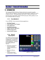
1.1. INTRODUCTION
The Fairbanks FB3000 II Solutions Series instrument is a powerful, versatile,
indicator which has flexibility, open architecture, and integrated capabilities of many
computer functions. With these abilities, the FB3000 II collects, processes, and
transmits data through RS232, RS485, RS422 serial ports, USB, parallel port, and
PCI 10/100 Mbs Ethernet interfaces.
1.1.1. The FB3000 II
Current FB3000 II Units include the following applications:
•
•
•
•
•
•
•
NewScale Program
Kernel Weight Server Program
In/Out Application
LabelBank Application
Highway System Application
SoftBatch Application
Interact Inside Program
1.1.2. Kernel
Description
The FB3000 II Kernel is weight
serving program for all FB3000
II applications. It provides the
core metrological functions for
all the applications. It includes
the following additional
features:
•
•
•
Multicasting capability to
monitor and operate
multiple scales across a
network.
Backup and Restore
feature.
Programmable Serial
Communication Outputs
02/10
The FB3000 II KERNEL is a Fairbanks-developed
Weight Server Program
6
51220 Rev. 1
Section 1: General Information
Kernel Description, Continued
•
Intalogix equipped units have load cell diagnostics features for easier
troubleshooting capabilities.
•
An integrated e-mail client is configurable to alert a service organization or
individual of a problem prior to total failure.
─ These error notifications include such warnings as load cell failure, low
memory, calibration change,
─ Flash memory error, and several other notifications to keep the proper
individuals informed of the scale’s operating condition.
─ Uses the customer’s existing email infrastructures, and requires a connection
to the customer’s Network.
─ Requires a connection to the customer’s PC Network.
•
The FB3000 II Kernel program is designed to function with platform scales
equipped with the following:
─ Intalogix™ Technology
─ Analog Load Cells
─ Mettler Toledo DigiTol™ Load Cells.
•
The instrument can control up to eight (8) scales.
•
Multi-scale viewing capability of up to four (4) scales at once is also a standard
feature.
•
The FB3000 II Kernel uses the following Modes of Operation:
─ Gross Only
─ GTN (Gross / Tare / Net)
02/10
7
51220 Rev. 1
Section 1: General Information
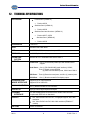
1.2. TECHNICAL SPECIFICATIONS
ENCLOSURE
•
Painted Steel (NEMA 12)
─ Product 30070
•
Stainless Steel (NEMA 12)
─ Product 30079
•
Stainless Steel and Aluminum (NEMA 12)
─ Product 30077; 30078
•
Stainless Steel (NEMA 4X)
─ Product 30079
PROCESSOR
1 GHz CPU
BIOS
Award® 512KB Flash BIOS
RAM
One DDR SO-DIMM memory socket up to 1GB
STORAGE
64 GB SSD (Solid State Drive)
OPERATING
SYSTEM
Microsoft XP Pro™ Embedded with Service Pack 2
OUTPUTS
Parallel Port – One (1) bi-directional parallel port with SPP/ECP/EPP
support.
Serial Ports – One (1) RS-232/422/485 (scale interface), COM 2;
Three (1) Board mounted RS232
(2) Case mounted RS232 ports, COM 3 and COM 4.
USB Ports – Three (2) Board mounted ports, and One (1) external ports.
SVGA Port – One (1) Board mounted SVGA display output.
KEYBOARD AND
MOUSE INTERFACE
Supports PS2 or USB keyboards
PC/104 CONNECTOR
One (1) Board mounted PC/104 connector
DIGITAL I/O
Eight (8) internal digital inputs and outputs
ETHERNET
INTERFACE
PCI 100/10 Mbps Ethernet interface with a female RJ45 connector.
Complies with IEEE 802.3x Standards
DISPLAY
Supports PS2 or USB mice
• 10.4” Color SVGA Color LCD-TFT; Full graphic support; 600 x 800
resolution
• 10.4” Color SVGA Color DVI; 600 x 800 resolution (FB3000 II T
models)
BATTERY
02/10
Lithium 3V/220mAH
8
51220 Rev. 1
Section 1: General Information
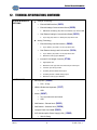
1.2. TECHNICAL SPECIFICATIONS, CONTINUED
SCALE INTERFACE
OPTIONS
•
Intalogix Technology
─ External QMB Interface (30433)
─ External Intalogix Communication Board (28330)
Maximum of twenty (20) 1000 Ω or twelve (12) 350 Ω cells
─ Dual External Intalogix Communication Board (28333)
•
Up to forty (40) 1000 Ω or twenty-four (24) 350 Ω cells
Analog Technology
─ External Analog Load Cell Interface (29646)
Up to sixteen (16) 1000 Ω or ten (10) 350 Ω cells
─ Dual External Analog Load Cell Interface (30124)
Up to sixteen (32) 1000 Ω or ten (20) 350 Ω cells
Maximum of two (2) per FB3000 II.
─ Internal PC104 Weight Controller (27104)
ACCESSORIES
•
High Speed A/D
Maximum of ten (10) 1000 ohm load cells per scale input
Controls up to two (2) scales
Provides passive 20mA serial output
Provides passive 4-20mA analog output
Maximum of two (2) per FB3000 II.
Mini keyboard (25498)
─ PS2 – 87 key
•
NEMA 4 Rubberized keyboard (27077)
─ USB
•
Mouse (26387)
─ Two (2) button with scroll wheel
─ USB
•
Wall Bracket – Painted Steel (26223)
•
Wall Bracket – Stainless Steel (26224)
•
Compact Flash Card 32MB (25853)
•
SVP/ Uninterruptible Power Supply (UPS) (15892)
─ 500 VA Rating
02/10
9
51220 Rev. 1
Section 1: General Information
1.2. TECHNICAL SPECIFICATIONS, CONTINUED
ACCESSORIES
CONTINUED
•
External Serial Port Relay Kit (26727)
─ Basic traffic light control (Interact)
•
4-20mA analog and 20mA serial output (27104)
─ PC140 Weight Controller
POWER
REQUIREMENTS
100 - 130 VAC @ 12A @ 60 Hz +/- 2 Hz
─ Separate and dedicated circuit.
─ Neutral to Ground voltage should be < 0.2 vAC
ETL LISTED
APPROVALS
•
Conforms to UL STD 60950-1.
•
CAN/CSA
•
CC# 04-013;
•
MC# M-5552C
C 22.2 NO.60950-1-03.
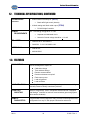
1.3. FEATURES
DIAGNOSTICS
Built-in self diagnostics reports on:
•
Calibration change
•
Time and date change
•
Remote access enabled
•
Routine maintenance required’
•
Flash memory error
•
Load cell ghosted
•
Load cell failure
LOAD CELL FLAG
Visual “flags” identify problem load cell(s) on diagnostic screen until flag is
manually cleared to identify intermittent problems
LOAD CELL
GHOSTING
Ability to electronically “mimic” or duplicate a failed load cell if equipped
with Intalogix™ Interface for load cell communications (preventing system
failure and/or shutdown)
REMOTE
DIAGNOSTICS
Programmable Remote Diagnostic Utility provides remote diagnostics and
configuration from any PC with proper authorization and access
02/10
10
51220 Rev. 1
Section 1: General Information
1.3. FEATURES, CONTINUED
EMAIL ERROR
REPORTING
Built-in email client for reporting error conditions such as the following:
•
Calibration change
•
Time and date change
•
Flash memory error
•
Remote access enabled
•
Routine maintenance required
•
Load cell ghosted
•
Load cell failure
ERROR DISPLAYING
Programming-selected display of error messages
BACKUP
Features the ability to backup information to optional Flash Memory card,
network or USB pen drive
WEB BROWSER
Built-in browser allowing web access for software updates and web site
viewing if desired
02/10
11
51220 Rev. 1
Section 2: Customer Responsibility
2.1. USERS’ RESPONSIBILITIES
It is the customer/operator's
responsibility to ensure the
equipment provided by Fairbanks is
operated within the parameters of
the equipment's specifications and
protected from accidental or
malicious damage.
W A R N I N G !
Absolutely no physical, electrical or program modifications other
than selection of standard options and accessories can be made
by customers to this equipment
Repairs are performed by Fairbanks Scales Service Technicians
and Authorized Distributor Personnel ONLY!
Failure to comply with this policy voids all implied and/or written
warranties
02/10
12
51220 Rev. 1
Section 2: Customer Responsibility
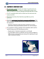
2.2. EQUIPMENT/ COMPONENT CARE
9
Do not remove power from this unit unless it is performed by the
proper shut down method. Failure to comply with the proper shut
down procedures can result in damage to the hard disk drive or data.
9
The AC receptacle/outlet shall be located near the instrument and
easily accessible.
9
Electrical connections other than those specified may not be
performed.
9
Absolutely no physical, electrical or program modifications other
than selection of standard options and accessories are to be made to
this equipment.
─
9
Electrical connections other than those specified may not be
performed, and physical alterations (holes, etc.) are not allowed.
The equipment consists of printed circuit assemblies which must be
handled using proper ESD handling procedures.
─
Replacement of individual components is not allowed.
─
Any assemblies which are replaced must be properly packaged in
ESD protective material if they are returned for replacement credit
under a warranty condition.
02/10
13
51220 Rev. 1
Section 3: Key Functions and Menus
3.1. KEY FUNCTIONS
On-Screen
Keyboard
External
Description
Keyboard
Arrows
Arrows
Menu Button
Esc
Zero
Pause
Break
Print
Prt Sc
02/10
•
•
•
•
Navigates through the display.
Used also for scrolling.
Changes the display to the Operation Menu.
Returns user to the previous menu.
Key(s) will Zero the Scale.
Prints a ticket.
• In the In/Out Device, an Inbound or Outbound Gross
ticket.
• A Gross, Tare, Net ticket may also be printed.
• In the Weigh Only mode, a Gross Weight ticket may be printed
with a manually entered Tare and the Net will be calculated.
14
51220 Rev. 1
Section 3: Key Functions and Menus
3.1. KEY FUNCTIONS, CONTINUED
On-Screen
Keyboard
External
Keyboard
Description
Units
Scroll Lock
Changes the units of weight displayed, depending on the selection
made in the Calibration Menu.
0 to 9
0 to 9
Used to enter numeric data, such as tares and IDs.
Enter
Enter
Stores selections into memory during data entry or programming.
F1
F1
Toggles between the scales that are viewed and operated.
F2
F2
Unassigned
F3
F3
Unassigned
F4
F4
Unassigned
F5
F5
Toggles between the scale groups when more than four (4) scales are
used.
F6
F6
Toggles between the Operational Screen and the Multi-Scale
Screen, if more than one scale is being controlled.
F7
Unassigned
F8
Unassigned
F9
Unassigned
F10
•
F11
Unassigned
F12
Unassigned
Service Usage only. !!Warning!! changing this items in this area
can effect the proper operation of the scale.
The Kernel can be set up to operate in one of two Modes of Operation, depending
upon the service programming:
─
Gross Weighing
─
GTN (Gross / Tare / Net)
Additional Windows Tips
•
ALT + F4 key
Shuts down the active program immediately
•
Windows Key + D
Moves to the Desktop
•
Windows Key + E
Opens MS Windows Explorer™
02/10
15
51220 Rev. 1
Section 3: Key Functions and Menus
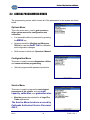
3.2. GENERAL PROGRAMMING MENUS
The programming menus which contain all of the parameters for the system are listed
below.
Options Menu
This is the main menu, used to gain access to
other system menus for configuration and
calibration.
•
It is accessible without a password by pressing
the MENU key.
•
Access provided for Weights and Measures
Official to view the Audit Trail for calibration
and configuration changes.
•
Quick access to electronic Operators’ Manual.
Configuration Menu
This menu is used to access diagnostics utilities
and communications programming.
•
Optional programmable password protection.
Service Menu
This menu is used to program the metrological
parameters of the system, such as scale
capacity, calibration, and graduation size.
•
Must be password protected for all Legal For
Trade applications.
The Service Menu functions are used by
Fairbanks Authorized Service Personnel
ONLY.
02/10
16
51220 Rev. 1
Section 3: Key Functions and Menus
3.3. BACKING UP AND SAVING PROGRAM
CHANGES TO A FOLDER
Each time a programming change is made to the Kernel
Program, a Backup Changes popup window
appears.
─ The normal answer is
NO.
─ Either double-click the
or click the
.
NOTE: Save changes ONLY WHEN the programming change(s) are correct, and
the system is proven to operate properly for all conditions.
─ For backing up the changes to a folder, click either the
or on the Weight Screen’s keypad, click the
.
─ Each file is saved by the date.
─ (yyyymmdd.BAK).
IMPORTANT NOTE: Backup EVERY
Configuration change… EVERY TIME!
02/10
17
51220 Rev. 1
Section 4: Input / Output (I/O)
4.1. INTRODUCTION
Connectivity is one of the primary features of the FB3000 II and Kernel Weight
Server program. The FB3000 II has multiple RS232 ports, USB ports, Ethernet
port, and a Parallel port to name a few. This section will provide steps in order to
connect the FB3000 II in a variety of manners to a variety of devices.
4.2. 4.2. CONFIGURE OUTPUT
4.2.1. Introduction
This menu selection provides a means to configure data strings protocols,
configuration parameters, and output modes such as Continuous, Demand,
Auto, To File, and Network.
4.2.2. Configuring an Output Data String
In order to interface an FB3000 II Instrument to software or a pre-existing
peripheral device, such as a remote display, knowing their specific Output
Data String is mandatory.
─ This allows the software or peripheral device to communicate with the
FB3000 II.
─ When adding to other manufacturer’s devices, refer to their Service
Manuals for Output Data String information.
─ Interfacing with other manufacturer’s software, refer to either a web site,
Service Manual, or contact the manufacturer directly for the Output Data
String information.
Fairbanks’ current programming for setting up an Output Data String
provides quick and easy flexibility for customizing the FB3000 II Serial
Outputs.
4.2.3. Two Methods of Formatting
There are two methods to format an Output Data String.
1. Use one of the five (5) preconfigured Load Defaults under the Load
tab.
2. Use the most similar Load Default as a basis for customizing an
Output Data String which matches the manufacturer’s company-specific
configuration. This method is done in the Build tab.
02/10
18
51220 Rev. 1
Section 4: Input/Output (I/O)
4.2.4. Load Default Data Protocols
When programming a Output Data String, the Fairbanks’ FB3000 II has five of the
most commonly used pre-configurations, known as Load Defaults. These data
strings are listed below:
Fairbanks
<STX><A><B><C><GGGGGG><TTTTTT><CR>
Toledo
<STX><A><B><C><GGGGGG><TTTTTT><CR>
Cardinal
<CR><P><WWWWWW><m><SP><U><SP><g><SP><SP><ETX>
Weightronix
< ><M><WWWWWW>< ><U><CR><LF>
Condec
<STX><P><WWWWWWW><U><G><M><CR>
4.2.5. Load the Default COM Settings
Follow these steps to configure the Load Default into the Output Data String.
3. From the Weighing Application
Window, press the MENU button,
from the Kernel Options Menu, select
Configuration Menu.
4. Select Configure Output..
02/10
19
51220 Rev. 1
Section 4: Input/Output (I/O)
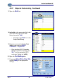
4.2.5. Load the Default COM Settings, Continued
5. Open the Load tab.
6. Select the COM Port to be
configured.
7. Sect the appropriate Load
Default.
8. Press the
button.
9. Open the Port Settings tab.
10. Program the Baud Rate, Stop
Bits, and the Parity to the
appropriate settings.
02/10
20
51220 Rev. 1
Section 4: Input/Output (I/O)
4.2.6. Customizing the Output Data Strings
The FB3000 II Kernel Weight Server program can also be customized to support
numerous manufacturers software interfaces and peripheral devices. When
programming a Data String Protocol not formatted as one of the Load Defaults,
the Output Data String must be programmed manually using the Build,
Tokens, and Weights Tabs.
4.2.7. Steps in Customizing
Follow these steps to customize the Output Data String.
11. Locate the required Output Data String by viewing history from previous work
completed with the customer, or by emailing and/or calling the company directly
and asking their IT Department for this information.
12. Compare the required Output Data String with the five Load Default
configurations.
13. Open the Load tab.
14. Select the COM Port to be
configured.
15. Select the Load Default that
most resembles the required
Output Data String format.
16. Press the
02/10
button.
21
51220 Rev. 1
Section 4: Input/Output (I/O)
4.2.7. Steps in Customizing, Continued
17. Open the Build tab.
18. Left-click on the appropriate field to be
generated within the specific data
string, then select Text.
─ This adds a new
Text box to the
Output Data String.
19. Program a command within the Data
String, either enter an ASCII
Character, or input text.
─ When inputting ASCII Characters,
always precede the message with
“0x...” and the equivalent ASCII
code up to 3 digits (i.e. 0x099).
20. Open the Port Settings tab.
21. Program the Baud Rate, Stop Bits,
and the Parity to the appropriate
settings.
02/10
22
51220 Rev. 1
Section 4: Input/Output (I/O)
4.2.7. Steps in Customizing, Continued
A drop-down Menu Window opens
when any Data Type choice is
selected by left-clicking in the field
Window Name
Description
CONFIGURE OUTPUT,
Configures the data string protocol order, written in ASCII text.
By left-clicking in any item, a drop-down menu offers different
parameters, or removes them.
─ Build Tab
Text may be added to the data string by clicking in the Value field, then
entering it.
─ Also by clicking into the Data Type box and choosing text from
the drop down box.
02/10
23
51220 Rev. 1
Section 4: Input/Output (I/O)
4.2.8. ASCII and Text Data Character Types
There are two types of data configuration characters. Both have an important and
have a specific function; both are used within the same data string. Both types are
defined below.
ASCII (American Standard Code for Internet Interchange) Characters
─ Text Formatted Characters are always written with a “0x_
_ _ ” prefix,
which tells the Kernel Program Read-me Trigger to post it as text character
(i.e. 0x120).
─ A code for information exchange between computers using a string of seven
(7) binary digits represents each character.
─ Each character identifies either a alphanumeric symbol (i.e. 065 = A, 066 = B,
etc.) or invokes an on-screen action (i.e. 013 = CR = Carriage Return).
─ One
Text Block must be added to the Data String for each character before
formatting it.
─ The data entries use decimal-based ASCII character codes.
─ Complete ASCII Chart found in Appendix
IV.
Text Formatted Characters
Text block must be added to the Data String before formatting the next
character.
─ A
─ These Text Formatted Characters are used to add a specific message to the
Service Technician, and it is done in combination with the text and with other
ASCII Text Characters.
02/10
24
51220 Rev. 1
Section 4: Input/Output (I/O)
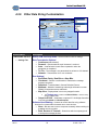
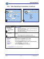
4.2.9. Other Data String Customization
Window Name
Description
CONFIGURE OUTPUT
RS232 COM Port Drop-down – Selects COM Port with its settings.
Data Transmission Options*
─ Continuous [transmission]
─ Demand – Upon demand as a poll character is received
─ Auto – A transmission is sent when requested or when the
─ Settings Tab
transaction is completed.
─ To File – The message is not transmitted, but written to a file instead.
─ Network – Transmission via IP over a network.
Port Settings*
─ Baud Rate, Parity, Data Bits and Stop Bits.
─ Checksum – Returns a confirmation of transmission message
─
─
─
between computers.
Delimited – Transmits data in Comma Delimited Format.
Multicast – Method of networking scale weight information to other
FB3000 II instruments across a Network.
Map View – Displays data in a memory mapped location.
The Testapp.exe, located in the Kernel folder, is used to verify
memory mapped data,
─ Output to PC104 – Sends data to optional PC 104 Weight Controller
Card using the 20mA or 4-20mA outputs.
Software Hand Shaking – A means to control data flow using software
functions for communication between two or more devices.
─ None – Bits are sent to source computer constantly without waiting for
available receiving modem.
─ Both, Receive or Transmit – Determines which computer(s) wait
to accept the message packets.
02/10
25
51220 Rev. 1
Section 4: Input/Output (I/O)
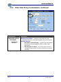
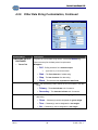
4.2.9. Other Data String Customization, Continued
Window Name
Description
CONFIGURE OUTPUT,
CONTINUED
Hardware Hand Shake – A means to control data flow using
─ Settings Tab,
Continued
hardware functions for communication between two or more devices.
Network Controls
─ DTR (Data Terminal Ready) – A control signal that indicates
that the Data Terminal Equipment (DTE) is ready for data
transmission.
─ RTS (Request To Send) – A control line which receives a
verification signal from the CTS Control Line when it is ready to
send data.
02/10
26
51220 Rev. 1
Section 4: Input/Output (I/O)
4.2.9. Other Data String Customization, Continued
Window Name
Description
CONFIGURE OUTPUT,
CONTINUED
Control Signals
─ DSR (Data Set Ready) – A control signal that indicates the
─ [Port] Settings
Tab
device is ready to transmit data.
─ CTS (Clear To Send) – A control signal used to notify the
device that it has line control.
─ Load Tab
Selects a preconfigured data protocol based on the scale manufacturer
selected.
─ Select this item first when configuring an output.
─ Press the OK button to load the data protocol selected.
DEFAULT DATA PROTOCOLS
Fairbanks
<STX><A><B><C><GGGGGG><TTTTTT><CR>
Toledo
<STX><A><B><C><GGGGGG><TTTTTT><CR>
Cardinal
<CR><P><WWWWWW><m><SP><U><SP><g><SP><SP><ETX>
Weightronix
< ><M><WWWWWW>< ><U><CR><LF>
Condec
<STX><P><WWWWWWW><U><G><M><CR>
** See Appendix
02/10
III for more formatting information.
27
51220 Rev. 1
Section 4: Input/Output (I/O)
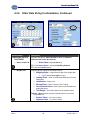
4.2.9. Other Data String Customization, Continued
Window Name
Description
CONFIGURE OUTPUT,
CONTINUED
Programs the various data string tokens, such as the Motion flag.
Tokens are setup for the data protocol requirements.
─ Tokens Tab
Wrappers
─ Poll – Polling character for a demand output.
Applicable only to the Demand Mode.
─ Start – The first character of a data string.
─ Stop – The last character of a data string.
─ Block – The character that separates the data fields.
Units – The character(s) used to define the unit of measure in the data
string
─ Primary – The main indicator unit of measure.
─ Secondary – The alternate indicator unit of measure.
Mode – The character(s) used to define the Weighing Mode in the
data string.
─ Gross – Character(s) used to designate the gross weight.
─ Tare – Character(s) used to designate the tare weight.
─ Net – Character(s) used to designate the net weight.
02/10
28
51220 Rev. 1
Section 4: Input/Output (I/O)
4.2.9. Other Data String Customization, Continued
Window Name
Description
CONFIGURE OUTPUT,
CONTINUED
Status – Identifies invalid weight conditions.
─ Motion – Character(s) used to identify the scale weight is in
─ Tokens Tab
motion.
─ Capacity – Character(s) used to identify the scale weight is
over capacity
─ OK – Character(s) used to identify the scale weight is valid.
─ Invalid – Character(s) used to identify the scale weight is
invalid.
02/10
29
51220 Rev. 1
Section 4: Input/Output (I/O)
4.2.9. Other Data String Customization, Continued
Window Name
Description
CONFIGURE OUTPUT,
CONTINUED
Programs data bits for Status Words A, B and C within the
Fairbanks and Toledo data streams.
─ Status Codes Tab
─ Status Word is eight (8) bits long.
22. Put the Status Words in the blank Data Entry Position.
23. Press the Loaded it button.
─ Weights Tab
Programs specific values for the Weight Tokens.
─ Weighing Digits – Programs the length of the weight data.
Typically six or seven digits in length.
─ Leading Zeros – When checked, adds leading zeros to the
weight data.
─ Justification – Right or left.
─ Decimal Point – None, Floating, Fixed, Trailing.
─ Fixed Decimal Places – Sets number of decimal places in
weight data string.
─ Test Weight – A manual weight entry to test data output.
Polarity – When checked, it places a polarity token in front of the
weight data item.
─ Positive Token – (+), None or Space
─ Negative Token – (), None or Space
02/10
30
51220 Rev. 1
Section 4: Input/Output (I/O)
4.3. 20 MA SERIAL CURRENT LOOP PROGRAMMING
Procedure steps skipped or omitted during this process may cause certain features to
not operate or function as expected. The 20 mA output is passive.
Note: The PC104 Weight Controller Kit (27104) must be installed for this output to
be available.
Procedure:
1. In the Kernel Weighing
Program, click the MENU
button to open the Configuration
Menu.
2. Open the Remote Display.
02/10
31
51220 Rev. 1
Section 4: Input/Output (I/O)
4.3. 20mA Serial Current Loop Programming, Continued
3. Set the Remote Display to COM 1.
4. Configure the Baud, Parity, Data Bits, and Stop Bits required.
5. Reset the Remote Display back to OFF.
6. Select the Enable 20ma Output check option.
7. Select ACTIVE in the Scale dropdown window.
8. Select Continuous in the
correct drop-down window.
1
02/10
32
51220 Rev. 1
Section 4: Input/Output (I/O)
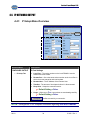
4.4. IP NETWORK OUTPUT
4.4.1. P Setup Menu Overview.
Window Name
Description
CONFIGURE OUTPUT
IP Port Settings
─ IP Setup Tab
•
Local Port – The socket number on the local FB3000 II used to
transmit and receive data.
•
Remote Port – Set to the same socket number as the Local Port in
which the remote transmits and receives data.
•
•
•
Remote Host – The IP Address of the Remote Host
TimeOut – The amount of time lapses before it is disconnected.
Keep Alive – Keeps the connection active.
9 Default Setting = False.
•
Linger – When set to True, connections are terminated gracefully.
9 Default Setting = False.
Verifies connectivity or connection.
NOTE: See Appendix IV for complete information regarding SOCKS Protocol.
02/10
33
51220 Rev. 1
Section 4: Input/Output (I/O)
4.4.1. IP Setup Menu Overview, Continued
Window Name
Description
CONFIGURE OUTPUT,
CONTINUED
Firewall Settings
─ IP Setup Tab
•
•
•
Host – The Host IP Address.
Port – The Port Socket number used.
Type
9 Default = No Firewall.
─ Tunnel – Set to 80.
─ SOCKS4* – Set to 1080.
─ SOCKS5* – Set to 1080.
•
•
•
User – User Login name
Password – User Password to login to the Host.
Connect – Establishes a connection.
Terminates all active connections.
Show a log of all IP events.
Stops the monitoring signal with the scale.
* See Appendix IV for complete information regarding SOCKS Protocol.
02/10
34
51220 Rev. 1
Section 4: Input/Output (I/O)
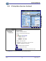
4.4.2. IP Network Output Setup Instructions
The following procedure outlines the setup instructions required to activate the IP
NETWORK output function. Procedure steps skipped or omitted during this process
may cause certain features to not operate or function as expected.
Follow these steps to configure the IP Network Output.
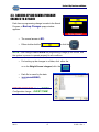
9. From the Weighing Application
Window, press the MENU button,
from the Kernel Options Menu, select
Configuration Menu.
10. Select Configure Output..
02/10
35
51220 Rev. 1
Section 4: Input/Output (I/O)
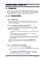
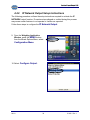
4.4.2. IP Network Output Setup Instructions, Continued
11. Select an unused COM Port to
be configured. Example: COM 5.
12. Access the Load tab and select a
default format similar to what is
required.
13. Press the
button.
.
14. Select the Build tab and configure the
data output format as desired.
02/10
36
51220 Rev. 1
Section 4: Input/Output (I/O)
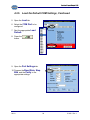
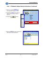
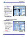
4.4.2. IP Network Output Setup Instructions, Continued
15. Use the Mode drop down list to
select the Network mode.
16. Select the IP Setup tab to
configure the network
parameters. Pointing to each
edit box will display a brief help
message, to assist in the setup
17. Program the IP Port Settings.
by setting the Local Port and
the Remote Port to the same
number as appropriate for the
users network.
Example: port = 2000.
•
Set the Remote Host to
one of the following
The IP address of the remote computer which will receive the weight data,
The network computer name of the remote computer which will receive the
weight data as in the example shown above.
18. Firewall Settings – Leave the
defaults as shown
19. The customer will need to
provide a receiving application
on a network computer which will
open a connection through a
TCP/IP socket with
•
•
The IP address must be set
to the address of the FB3000
II and the Port set to the
FB3000 II Local Port setting.
Example: 2000.
When the IP is configured
correctly, it will display
Listening.
20. The data steam will be a
continuous stream in the format set in step 6 above.
02/10
37
51220 Rev. 1
Section 4: Input/Output (I/O)
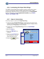
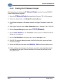
4.4.3. Testing the IP Network Output
Test Instructions to activate the IP Network Output function from the FB3000 II
Kernel Weight Server program.
1. Setup the IP Network Output as described in Section 7.6.2. of this manual.
2. Return the Kernel back to the Weight Processing Screen.
3. At a different computer on the same network, use Hyper-Terminal to receive the
data.
4. Start Hyper-Terminal, enter a New Connection name. Example: Test. Click OK.
5. Set the Connect Using drop down box to TCP/IP (Winsock).
7. Set the Host Address to the IP address of the computer or FB3000 II that the
Kernel.exe is running on.
7. Set the Port Number to the same value as the Local port is set.
8. Click OK. If a connect attempt is made, it will fail at this point, ignore and clear
the error message.
9. Select the Call menu item and select Wait for Call from the drop down menu.
10. If all is working, the instrument should make connection and weight data should
be displayed in the Hyper-Terminal window in the format set previously in the
setup instructions
02/10
38
51220 Rev. 1
Section 5: Operation
5.1. SYSTEM BOOT-UP PROCEDURE
Initiate the power up sequence using the power ON/OFF rocker switch located on
the bottom-left side of the instrument.
Normal indications include the following:
─ Lights on the keyboard should blink.
─ After approximately one minute, the
Fairbanks Logo appears along
with a mouse pointer, located approximately in the center of the screen.
─ The
Fairbanks Logo disappears.
─ A Windows welcome screen appears.
─ Lastly, a weighing application window appears.
02/10
39
51220 Rev. 1
Section 5: Operation
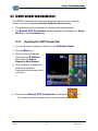
5.2. VIEWING OPTIONS
The Multi-Scale Screen application
The GTN Screen application
When using the Kernel Program, there are two viewing options for weighing.
The GTN Screen
The GTN Screen displays the weighments for only .one scale at a time.
Multi-scale Screen
The Multi-scale Screen displays all configured scales on the screen at one time.
─ The Golden Diamond show which weighment is being used
─ The scale being used is identified in the lower-left corner of the screen.
5.3. GROSS WEIGHING
1. Press the ZERO key to zero the scale.
2. Place the object to be weighed on the platform.
3. View the weight from the screen.
NOTE: The Operating Mode is Service-Programmable only.
02/10
40
51220 Rev. 1
Section 5: Operation
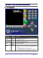
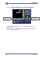
5.3.1. Using the Display Screen Function Buttons
F1 toggles thru the
F6 toggles the two
available scales
screen views
•
When in the Multi-scale Screen, press the F1 button to toggle thru the
available scales.
•
Press the display screen’s F6 button to toggle back-and-forth from the GTN
Screen to the Multi-scale Screen.
02/10
41
51220 Rev. 1
Section 5: Operation
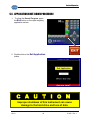
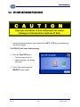
5.4. APPLICATION SHUT-DOWN PROCEDURE
1. To close the Kernel Program, press
the Exit button on the open weighing
application screen.
2. Double-click on the Exit Application
button.
C A U T I O N
Improper shutdown of this instrument can cause
damage to the hard drive and loss of data.
02/10
42
51220 Rev. 1
Section 5: Operation
5.5. SYSTEM SHUTDOWN PROCEDURE
C A U T I O N
Improper shutdown of this instrument can cause
damage to the hard drive and loss of data.
1. Using the external keyboard, press and hold the ALT + F4 keys simultaneously
to exit the program.
The FB3000 II will close down properly.
2. Click the Turn Off button.
─ The instrument turns off.
─ Upon shut down, the display
turns dark.
3. Turn off the power using the
ON/OFF rocker switch.
02/10
43
51220 Rev. 1
Section 6: SERVICE & MAINTENANCE
IMPORTANT PRECAUTIONS
Electrostatic Discharge (ESD) can easily damage the FB3000 II board assemblies.
Do not touch or handle internal components without proper precautions such as
utilizing a grounding strap.
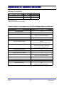
6.1. TROUBLESHOOTING
Error Condition(s)
Solution(s)
•
•
Check that scale is empty.
•
Load Cell(s) bad.
•
•
•
•
•
•
•
If Scale is empty, Call for
Service.
•
Flashing and displays “- - - -“ •
•
Load Cell Failure(s)
SC Cells Found None
Displays “
02/10
- - - - “ ~ lb GROSS
A large amount of weight is zeroed.
This is normal.
Press OK and continue weighing.
Possible load cell damage.
Call for Service.
Possible load cell damage.
Call for Service.
Access the Load Cell Diagnostics Menu to verify the
load cell status.
•
•
Count stability or change of counts.
•
•
•
•
•
•
Possible damaged load cell cable.
•
•
Communication error to load Cells.
Contact the local service for further trouble-shooting.
Load cell shortened.
Defective Pit Power Supply.
Defective Smart Sectional Controller(s).
Defective Analog Assembly.
Call for Service.
Call for Service.
44
51220 Rev. 1
Section 6: Service and Maintenance
6.2. REMOTE SERVICE AND DIAGNOSTICS
The FB3000 II can be serviced and have diagnostics performed from a remote
location, such as the nearest authorized Fairbanks Service Center.
•
The instrument must be connected to a network with internet access.
•
The Remote VNC Connection can be programmed to display in the Weight
Window or in the minimized tray.
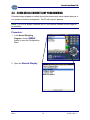
6.2.1. Opening the VNC Connection
1. To open the remote connection, left-click on the Fairbanks Globe.
2. Click the Menu key.
3. Give the Remote Fairbanks
Technician the IP address
listed within the Remote
Diagnostic Mode Window.
4. Upon completion of diagnostics,
the Remote Fairbanks
Technician will disconnect at his
or her end.
5. Disconnect the Remote VNC Connection by clicking the
box.
─ This returns the Kernel Program back to normal operations.
02/10
45
51220 Rev. 1
Appendix I: GPIO Port
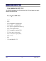
Programming the GPIO Port
The FB3000 II provides an 8-bit GPI port and an 8-bit GPO port that you can use to
read and write data through.
Reading the GPIO Data
•
2e,87
•
2e,87
•
2e,2a //configuration register(CR2a)
•
2f,fc //set GPIO ,not GAME PORT
•
2e,07 //point to logical device number reg
•
2f,07 //select logical device 7
•
2e,30 //configuration register(CR30)
•
2f,1 //open logical device control
•
2e,f0 //configuration register(CRf0)
•
2f,FF // 1=input
•
2e,f1
•
I 2f // read value (00 ~ FF)
02/10
46
51220 Rev. 1
Appendix I: GPIO Port
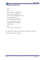
Writing the GPIO Data
•
4e,87
•
4e,87
•
4e,2a //configuration register(CR2a)
•
4f,fc //set GPIO ,not GAME PORT
•
4e,07 //point to logical device number reg.
•
4f,07 //select logical device 7
•
4e,30 //configuration register(CR30)
•
4f,1 //open logical device control
•
4e,f0 //configuration register(CRf0)
•
4f,00 // 0=output
•
4e,f1
•
4f,XX // XX= (00 ~ FF) output value
bit0 : GPI(O)1 bit1 : GPI(O)2 bit2 : GPI(O)3 bit3 : GPI(O)4 bit4 : GPI(O)5 bit5 :
GPI(O)6 bit6 : GPI(O)7 bit7 : GPI(O)8
02/10
47
51220 Rev. 1
Appendix II: System Resource
Interrupt Controller
The FB3000 II embedded PCB is a fully PC compatible control board. It consists of
16 ISA interrupt request lines. Most of them are already in use by other parts of the
board. Both ISA and PCI expansion cards may need to use IRQs, so make sure the
IRQs do not conflict when using add-on cards.
System IRQs are available to cards installed in the ISA expansion bus first. Any
remaining IRQs then may be assigned to the PCI bus. Check out an AMI
diagnostic utility to see the map.
02/10
48
51220 Rev. 1
Appendix II: System Resource
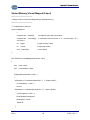
Shared Memory (Kernel Mapped Output)
//***********************************
// Sample code to read Kernel Mapped Output (Shared Memory)
//***********************************
// FileMap Memory Structure
struct FileMapStruct
{
unsigned char
data[256];
// configured output string from kernel
unsigned char
zero scale 1
command[2];
// command to return to kernel i.e. “z” = zero all scales, “Z1” =
int
length;
// length of string in data
int
counter;
// sequential number
char
status[128];
// kernel status
};
bool TScaleForm::ReadMappedOutput(char *input)
{
bool
result = false;
bool
CommandSent = false;
if( MappedOutputHandle == NULL )
{
wSemaphore = CreateSemaphore(NULL, 1, 1, “Output1 Write");
if( wSemaphore == NULL )
return 0;
rSemaphore = CreateSemaphore(NULL, 0, 1, “Output1 Read");
if( rSemaphore == NULL ) {
CloseHandle(wSemaphore);
wSemaphore = NULL;
return 0;
}
02/10
49
51220 Rev. 1
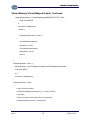
Appendix II: System Resource
Shared Memory (Kernel Mapped Output), Continued
MappedOutputHandle = CreateFileMapping((HANDLE)0xFFFFFFFF, NULL,
PAGE_READWRITE,
0,
sizeof(struct FileMapStruct),
“Output1”);
if( MappedOutputHandle == NULL )
{
CloseHandle(rSemaphore);
rSemaphore = NULL;
CloseHandle(wSemaphore);
wSemaphore = NULL;
return 0;
}
}
if( MapOutputData == NULL ) {
MapOutputData = (struct FileMapStruct*)MapViewOfFile(MappedOutputHandle,
FILE_MAP_WRITE,
0, 0,
sizeof(struct FileMapStruct));
}
if( MapOutputData != NULL )
{
// wait for kernel to release
if( WaitForSingleObject(rSemaphore, 5) == WAIT_FAILED )
return false;
// Check Counter to see if Kernel has sent a new string
if( MapOutputData->counter != LastCounter )
02/10
50
51220 Rev. 1
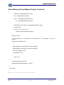
Appendix II: System Resource
Shared Memory (Kernel Mapped Output), Continued
{
LastCounter = MapOutputData->counter;
int len = MapOutputData->length;
if( len > sizeof(MapOutputData->data)-1 )
len = sizeof(MapOutputData->data)-1;
ScaleStatus_Text->Caption = (String)MapOutputData->status;
input[0] = NULL;
for ( int mf = 0; mf < len; mf++ ) {
input[mf] = MapOutputData->data[mf];
}
input[len] = NULL;
// return command i.e. ‘z’ to zero scales, ‘u’ to change units etc… (2 char buffer… ‘Z1’ to zero
scale 1)
if( KernelCommand[0] != NULL )
{
MapOutputData->command[0] = KernelCommand[0];
MapOutputData->command[1] = KernelCommand[1];
KernelCommand[0] = NULL;
CommandSent = true;
}
result = true;
}
// release semaphore for kernel
ReleaseSemaphore(wSemaphore, 1, NULL);
}
return result;
}
//---------------------------------------------------------------------------
02/10
51
51220 Rev. 1
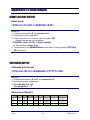
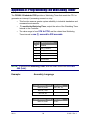
Appendix III: Data Output
REMOTE DISPLAY OUTPUT
Data Format
<STX><4><0><SP/-><XXXXXX><ETX>
Note(s):
1. Characters denoted by X are characters 0-9.
2. Leading zeroes are suppressed.
3. Polarity indication for a positive value is a space (SP).
− Negative values are not transmitted.
4. Identifier code <4><0> = Gross weight.
− Transmission is Gross Only.
5. Transmission for the DEMAND Mode occurs when a carriage return (CR) Hex
0D is received.
CONFIGURE OUTPUT
Fairbanks Data Format
<STX><A><B><C><GGGGGG><TTTTTT><CR>
Note(s):
1. Characters denoted by G and T are characters 0-9.
2. Leading zeroes are suppressed.
3. Gross Weight Data = G
Tare Weight Data = T
Status Code (Word) A
Bit #
X00
X0
X
X.X
X.XX
X.XXX
X.XXXX
X.XXXXX
0
0
1
0
1
0
1
0
1
1
0
0
1
1
0
0
1
1
2
0
0
0
0
1
1
1
1
02/10
52
51220 Rev. 1
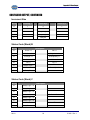
Appendix III: Data Output
CONFIGURE OUTPUT, CONTINUED
Increment Size
Bit #
Count By 1
Count by 2
Count by 5
3
1
0
1
4
0
1
1
5
Always Logic 1
6
Always Logic 0
7
Parity Bit
Status Code (Word) B
Bit #
Description
0
Gross = 0
Net = 1
1
Positive = 0
Negative = 1
2
In Range = 0
Overcapacity = 1
3
No Motion = 0
Motion = 1
4
Lb = 0
Kg = 1
5
Always Logic 1
6
Normal = 0
7
Parity Bit
Power Up = 1
Status Code (Word) C
Bit #
Description
0
Always Logic = 0
1
Always Logic = 0
2
Always Logic = 0
3
Normal = 0
4
Always Logic = 0
5
Always Logic = 0
6
Normal = 0
7
Parity Bit
02/10
Print Switch Pushed = 1
Keyboard Tare = 1
53
51220 Rev. 1
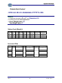
Appendix III: Data Output
Toledo Data Format
<STX><A><B><C><GGGGGG><TTTTTT><CR>
Note(s):
1. Characters denoted by G and T are Characters 0-9.
2. Leading zeroes are not suppressed.
3. Gross Weight data = G
Tare Weight data = T
Status Code (Word) A
Bit #
X00
X0
X
X.X
X.XX
X.XXX
X.XXXX
X.XXXXX
0
0
1
0
1
0
1
0
1
1
0
0
1
1
0
0
1
1
2
0
0
0
0
1
1
1
1
Increment Size
Bit #
Count By 1
Count by 2
Count by 5
3
1
0
1
4
0
1
1
5
Always Logic 1
6
Always Logic 0
7
Parity Bit
02/10
54
51220 Rev. 1
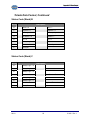
Appendix III: Data Output
Toledo Data Format, Continued
Status Code (Word) B
Bit #
Description
0
Gross = 0
Net = 1
1
Positive = 0
Negative = 1
2
In Range = 0
Overcapacity = 1
3
No Motion = 0
Motion = 1
4
Lb = 0
Kg = 1
5
Always Logic = 0
6
Normal = 0
7
Parity Bit
Power Up = 1
Status Code (Word) C
Bit #
Description
0
Always Logic = 0
1
Always Logic = 0
2
Always Logic = 0
3
Normal = 0
4
Always Logic = 0
5
Always Logic = 1
6
Normal = 0
7
Parity Bit
02/10
Print Switched Pushed = 1
Keyboard Tare = 1
55
51220 Rev. 1
Appendix III: Data Output
Cardinal 738 Continuous Scoreboard Data Format
<CR><P><WWWWWW><m><SP><U><SP><g><SP><SP><ETX>
Note(s):
1. W = Displayed weight
P = Polarity
+ = Positive weight
- = Negative weight
U = Units
lb = pounds
kg = kilograms
m = Motion or o = Overload
g = Gross; n = Net
SP = Space
2. Leading zeros are not suppressed.
Weightronix Data Format
< ><M><WWWWWW>< ><U><CR><LF>
Note(s):
1. < > = Space
M = Mode
G =Gross
T=Tare
N=Net
W = Displayed weight
U = Units
m = Motion
o = Overload
2. Leading zeros are suppressed.
02/10
56
51220 Rev. 1
Appendix III: Data Output
Condec Continuous Data Format
<STX><P><WWWWWW><U><G><M><CR>
Note(s):
1. P = Polarity
space = positive weight
- = negative weight
W = Displayed weight
U = Units
L = pounds
K = kilograms
G = Gross; N = Net
M = Motion
2. Leading zeros are suppressed.
Build Tab Definitions
Load Cell Status <L> This item, if included in the data output string, indicates if a
load cell(s) are indicating an error. If no error is present, a zero (0) will be present or
the character equivalent of the decimal number of load cell with an error will be
indicated. i.e. 1 = <SOH>, 28 = <FS>
02/10
57
51220 Rev. 1
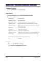
Appendix IV: Network Command Functions
Command Structure:
[Sender],[COMMAND],Command,[End][LF]
Where Sender is:
The Computer Name of the PC which is sending the command.
Where Command is:
Lowercase z =
Zeroes all scales.
Uppercase Z1, Z2, etc =
Zero a specific scale.
Uppercase ZA or ZB =
Zero Group ScaleA (1 to 4) or Group ScaleB (5 to 8).
Uppercase Txxxxx =
Apply Tare xxxxx to Active scale where xxxxx = Tare value.
Uppercase T#,xxxxx =
Apply Tare xxxxx to Selected scale # where xxxxx = Tare value
and # = Scale number.
Uppercase A =
Auto Tare Active scale
Lowercase u =
Change units on all scales.
Uppercase U1, U2, etc. =
Change units on a specific scale.
Uppercase UA or UB =
Change units on Group ScaleA (1 to 4) or Group ScaleB (5 to 8).
Uppercase S# =
Make Scale # (1-8) the Active scale where # = Scale number.
Poll Character (see Configured Output) sends configured output.
LF =
Line Feed
Example:
[Freds PC],[COMMAND],Z1,[End][LF]
i.e. – Freds PC is requesting Scale 1 to Zero.
02/10
58
51220 Rev. 1
Appendix V: Programming the Watchdog Timer
The FB3000 II Embedded PCB provides a Watchdog Timer that resets the CPU or
generates an interrupt if processing comes to a stop.
─ This function ensures greater system reliability in industrial standalone and
unmanned environments.
─
T o enable the Watchdog Timer, output the value of the Watchdog Timer
Interval to the Controller.
01H to FFH, and the related time Watchdog
Timer interval is one (1) second to 255 seconds.
─ The value range is from
DATA
TIMER INTERVAL
00
Disabled
01
One (1) second
02
Two (2) seconds
*
*
*
*
FF
255 seconds
NOTE: To program the Watchdog Timer, write the timer value to the I/O Port
444 (hex).
Example:
Assembly Language
Start Watchdog Timer
DOS Debug
MOV DX, 444H
OUT 444, XX
MOV AL, XXH
OUT DX, AL
Start Watchdog Timer
MOV DX, 444H
DOS Debug
IN 441
IN AL, DX
02/10
59
51220 Rev. 1
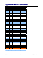
Appendix VI: Kernel 20mA Codes
Code
00
40
41
42
43
44
45
46
47
48
49
50
51
52
53
54
55
56
57
58
59
60
61
62
63
64
65
66
67
68
69
70
71
72
73
74
75
76
77
78
79
80
81
82
83
84
85
86
87
Units
lbs
lbs
lbs
kg
kg
kg
lbs
lbs
lbs
kg
kg
kg
lbs
lbs
lbs
kg
kg
kg
lbs
lbs
lbs
kg
kg
kg
lbs
lbs
lbs
kg
kg
kg
lbs
lbs
lbs
kg
kg
kg
lbs
lbs
lbs
kg
kg
kg
lbs
lbs
lbs
kg
kg
kg
Data Displayed
Display all data.
Gross
Net
Tare
Gross
Net
Tare
Gross
Net
Tare
Gross
Net
Tare
Gross
Net
Tare
Gross
Net
Tare
Gross
Net
Tare
Gross
Net
Tare
Gross
Net
Tare
Gross
Net
Tare
Gross
Net
Tare
Gross
Net
Tare
Gross
Net
Tare
Gross
Net
Tare
Gross
Net
Tare
Gross
Net
Tare
99
lbs
TOTAL
Scale #
1
1
1
1
1
1
2
2
2
2
2
2
3
3
3
3
3
3
4
4
4
4
4
4
5
5
5
5
5
5
6
6
6
6
6
6
7
7
7
7
7
7
8
8
8
8
8
8
For FB3000 II
HWY SYS
* Existing 2500 output (excluding HWY SYS application
02/10
60
51220 Rev. 1
Appendix VII: SOCKS Information
SOCKS is an Internet Protocol that allows client-server applications to transparently
use the services of a network firewall.
─ SOCKS is an abbreviation for “sockets”.
─ Clients behind a firewall, needing to access exterior servers, may connect
to a SOCKS proxy server instead. Such a proxy server controls the
eligibility of the client to access the external server and passes the request
on to the server.
─ SOCKS can also be used in the opposite way, allowing the clients outside
the firewall (exterior clients) to connect to servers inside the firewall
(internal servers).
A typical SOCKS 4 connection request looks like the following (each number is one
byte).
Client to SOCKS Server:
•
Field 1: SOCKS version number, 1 byte, must be 0x04 for this version
•
Field 2: Command code, 1 byte:
─ 0x01 = Establish a TCP/IP stream connection.
─ 0x02 = Establish a TCP/IP port binding.
•
Field 3: Network byte order port number, 2 bytes.
•
Field 4: Network byte order IP address, 4 bytes.
•
Field 5: The user ID string, variable length, terminated with a null (0x00).
Server to SOCKS client:
•
Field 1: Null byte.
•
Field 2: Status, 1 byte:
─ 0x5a = Request granted.
─ 0x5b = Request rejected or failed.
─ 0x5c = Request failed because client is not running identd (or not
reachable from the server).
─ 0x5d = Request failed because client’s identd could not confirm the user ID
string in the request.
•
Field 3: 2 arbitrary bytes, that should be ignored.
•
Field 4: 4 arbitrary bytes, that should be ignored.
02/10
61
51220 Rev. 1
Appendix VII: SOCKS Information
APPENDIX VII: SOCKS INFORMATION, CONTINUED
The SOCKS 5 Protocol, an extension of the SOCKS 4 Protocol that offers more
choices of authentication, is defined in RFC 1928.
The initial handshake now consists of the following:
•
Client connects and sends a greeting which includes a list of authentication
methods supported.
•
Server chooses one (or sends a failure response if none of the offered methods
are acceptable).
•
Several messages may now pass between the client and the server depending on
the authentication method chosen.
•
Client sends a connection request similar to SOCKS 4.
•
Server responds similar to SOCKS 4.
The authentication methods supported are numbered as follows:
•
0x00 – No authentication.
•
0x01 – GSSAPI.
•
0x02 – Username/Password.
•
0x03-0x7F – Methods assigned by IANA.
•
0x80-0xFE – Methods reserved for private use.
The initial greeting from the client is:
•
Field 1: SOCKS version number (must be 0x05 for this version).
•
Field 2: Number of authentication methods supported, 1 byte.
•
Field 3: Authentication methods, variable length, 1 byte per method supported.
The server’s choice is communicated:
•
Field 1: SOCKS version, 1 byte (0x05 for this version).
•
Field 2: Chosen authentication method, 1 byte, or 0xFF if no acceptable methods
were offered.
02/10
62
51220 Rev. 1
Appendix VII: SOCKS Information
APPENDIX VII: SOCKS INFORMATION, CONTINUED
The subsequent authentication is method-dependent and described in RFC 1929.
The client’s authentication request is:
•
Field 1: Version number, 1 byte (must be 0x01).
•
Field 2: Username length, 1 byte.
•
Field 3: Username.
•
Field 4: Password length, 1 byte.
•
Field 5: Password.
Server response for authentication:
•
Field 1: Version, 1 byte.
•
Field 2: Status code, 1 byte.
─ 0x00 = success.
─ Any other value = failure, connection must be closed.
The client’s connection request is:
•
Field 1: SOCKS version number, 1 byte (must be 0x05 for this version).
•
Field 2: Command code, 1 byte:
─ 0x01 = establish a TCP/IP stream connection.
─ 0x02 = establish a TCP/IP port binding.
─ 0x03 = associate a UDP port.
•
Field 3: Reserved, must be 0x00.
•
Field 4: Address type, 1 byte:
─ 0x01 = Ipv4 address.
─ 0x03 = Domain name.
─ 0x04 = Ipv6 address.
•
Field 5: Destination address of:
─ 4 bytes for Ipv4 address.
─ 1 byte of name length followed by the name for Domain name.
─ 16 bytes for Ipv6 address.
•
Field 6: Port number in a network byte order, 2 bytes.
02/10
63
51220 Rev. 1
Appendix VII: SOCKS Information
APPENDIX VII: SOCKS INFORMATION, CONTINUED
Server response:
•
Field 1: SOCKS protocol version, 1 byte (0x05 for this version).
•
Field 2: Status, 1 byte:
─ 0x00 = Request granted.
─ 0x01 = General failure.
─ 0x02 = Connection not allowed by ruleset.
─ 0x03 = Network unreachable.
─ 0x04 = Host unreachable.
─ 0x05 = Connection refused by destination host.
─ 0x06 = TTL expired.
─ 0x07 = Command not supported / protocol error.
─ 0x08 = Address type not supported.
•
Field 3: Reserved, must be 0x00.
•
Field 4: Address type, 1 byte:
─ 0x01 = Ipv4 address.
─ 0x03 = Domain name.
─ 0x04 = Ipv6 address.
•
Field 5: Destination address of :
─ 4 bytes for Ipv4 address.
─ 1 byte of name length followed by the name for Domain name.
─ 16 bytes for Ipv6 address.
•
Field 6: Network byte order port number, 2 bytes.
02/10
64
51220 Rev. 1
Appendix VIII: Remote Functions
Hardware Connections
REMOTE FUNCTIONS
CN14
Remote Zero Switch
3
11 or 12
Remote Print Switch
9
11 or 12
*Dry contacts only.
**Must have I/O accessory installed.
Remote Software Commands using Serial Port/ Mapped Memory/ Multicast
02/10
FUNCTION
SOFTWARE COMMAND
Zero Active Scale
Z
Zero ALL Scales
z
Zero a Specific Scale
Z#
where # is the Scale number.
Zero Scales 1-4
ZA
Zero Scales 5-8
ZB
Set Tare on Active Scale
Txxxxx
where xxxxx is the Tare weight value.
Set Tare on a Specific Scale
T#, xxxxx
where # is the Scale number and
xxxxx is the Tare weight value.
AutoTare on Active Scale
A
Change Units on Active Scale
U
Change Units on ALL Scales
u
Change Units on Specific Scale
U#
where # is the Scale number.
Print Active Scale
P
Change to Multi-Screen
m
Change to GTN Screen
g
Select Active Scale
S#
where # is the Scale number.
65
51220 Rev. 1
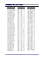
APPENDIX IX: ASCII CODES
02/10
66
51220 Rev. 1
Manufactured by Fairbanks Scales, Inc.
821 Locust
Kansas City, Missouri 64106
www.fairbanks.com
FB3000 II KERNEL
OPERATOR MANUAL
DOCUMENT 51220